JP2010075813A - Coating method - Google Patents
Coating method Download PDFInfo
- Publication number
- JP2010075813A JP2010075813A JP2008245506A JP2008245506A JP2010075813A JP 2010075813 A JP2010075813 A JP 2010075813A JP 2008245506 A JP2008245506 A JP 2008245506A JP 2008245506 A JP2008245506 A JP 2008245506A JP 2010075813 A JP2010075813 A JP 2010075813A
- Authority
- JP
- Japan
- Prior art keywords
- coating
- discharge
- nozzle
- discharge amount
- nozzles
- Prior art date
- Legal status (The legal status is an assumption and is not a legal conclusion. Google has not performed a legal analysis and makes no representation as to the accuracy of the status listed.)
- Pending
Links
- 238000000576 coating method Methods 0.000 title claims abstract description 212
- 239000011248 coating agent Substances 0.000 claims abstract description 162
- 239000007788 liquid Substances 0.000 claims abstract description 55
- 239000000463 material Substances 0.000 claims abstract description 30
- 238000001514 detection method Methods 0.000 claims abstract description 29
- 239000000758 substrate Substances 0.000 claims description 32
- 238000005259 measurement Methods 0.000 claims description 13
- 230000007423 decrease Effects 0.000 claims description 10
- 238000007599 discharging Methods 0.000 claims description 5
- 230000005540 biological transmission Effects 0.000 claims description 2
- 239000010408 film Substances 0.000 description 91
- 238000009826 distribution Methods 0.000 description 22
- 238000000034 method Methods 0.000 description 19
- 238000012545 processing Methods 0.000 description 7
- 239000000243 solution Substances 0.000 description 7
- 239000010409 thin film Substances 0.000 description 5
- 230000015572 biosynthetic process Effects 0.000 description 4
- 238000010586 diagram Methods 0.000 description 4
- 238000004519 manufacturing process Methods 0.000 description 4
- 239000000123 paper Substances 0.000 description 4
- -1 polyethylene Polymers 0.000 description 4
- 230000003746 surface roughness Effects 0.000 description 4
- 238000012937 correction Methods 0.000 description 3
- 238000001035 drying Methods 0.000 description 3
- 238000002347 injection Methods 0.000 description 3
- 239000007924 injection Substances 0.000 description 3
- 239000004698 Polyethylene Substances 0.000 description 2
- 238000005452 bending Methods 0.000 description 2
- 230000000052 comparative effect Effects 0.000 description 2
- 230000003247 decreasing effect Effects 0.000 description 2
- 238000011156 evaluation Methods 0.000 description 2
- 238000010438 heat treatment Methods 0.000 description 2
- 239000004973 liquid crystal related substance Substances 0.000 description 2
- 229910052751 metal Inorganic materials 0.000 description 2
- 239000002184 metal Substances 0.000 description 2
- 239000002985 plastic film Substances 0.000 description 2
- 229920006255 plastic film Polymers 0.000 description 2
- 229920000573 polyethylene Polymers 0.000 description 2
- 229920000139 polyethylene terephthalate Polymers 0.000 description 2
- 239000005020 polyethylene terephthalate Substances 0.000 description 2
- 238000005303 weighing Methods 0.000 description 2
- NQBXSWAWVZHKBZ-UHFFFAOYSA-N 2-butoxyethyl acetate Chemical compound CCCCOCCOC(C)=O NQBXSWAWVZHKBZ-UHFFFAOYSA-N 0.000 description 1
- 229920002284 Cellulose triacetate Polymers 0.000 description 1
- 229920000742 Cotton Polymers 0.000 description 1
- 239000004952 Polyamide Substances 0.000 description 1
- 239000004743 Polypropylene Substances 0.000 description 1
- NNLVGZFZQQXQNW-ADJNRHBOSA-N [(2r,3r,4s,5r,6s)-4,5-diacetyloxy-3-[(2s,3r,4s,5r,6r)-3,4,5-triacetyloxy-6-(acetyloxymethyl)oxan-2-yl]oxy-6-[(2r,3r,4s,5r,6s)-4,5,6-triacetyloxy-2-(acetyloxymethyl)oxan-3-yl]oxyoxan-2-yl]methyl acetate Chemical compound O([C@@H]1O[C@@H]([C@H]([C@H](OC(C)=O)[C@H]1OC(C)=O)O[C@H]1[C@@H]([C@@H](OC(C)=O)[C@H](OC(C)=O)[C@@H](COC(C)=O)O1)OC(C)=O)COC(=O)C)[C@@H]1[C@@H](COC(C)=O)O[C@@H](OC(C)=O)[C@H](OC(C)=O)[C@H]1OC(C)=O NNLVGZFZQQXQNW-ADJNRHBOSA-N 0.000 description 1
- 238000007754 air knife coating Methods 0.000 description 1
- 229910052782 aluminium Inorganic materials 0.000 description 1
- XAGFODPZIPBFFR-UHFFFAOYSA-N aluminium Chemical compound [Al] XAGFODPZIPBFFR-UHFFFAOYSA-N 0.000 description 1
- 238000007611 bar coating method Methods 0.000 description 1
- 238000009835 boiling Methods 0.000 description 1
- 238000004364 calculation method Methods 0.000 description 1
- 229920002301 cellulose acetate Polymers 0.000 description 1
- 238000004140 cleaning Methods 0.000 description 1
- 238000007766 curtain coating Methods 0.000 description 1
- 239000002270 dispersing agent Substances 0.000 description 1
- 239000000428 dust Substances 0.000 description 1
- 230000000694 effects Effects 0.000 description 1
- 238000005516 engineering process Methods 0.000 description 1
- 238000007765 extrusion coating Methods 0.000 description 1
- 230000001678 irradiating effect Effects 0.000 description 1
- 239000011344 liquid material Substances 0.000 description 1
- 239000012528 membrane Substances 0.000 description 1
- 239000003595 mist Substances 0.000 description 1
- 238000012544 monitoring process Methods 0.000 description 1
- 230000003287 optical effect Effects 0.000 description 1
- 229920002120 photoresistant polymer Polymers 0.000 description 1
- 239000000049 pigment Substances 0.000 description 1
- 229920001643 poly(ether ketone) Polymers 0.000 description 1
- 229920002647 polyamide Polymers 0.000 description 1
- 229920006267 polyester film Polymers 0.000 description 1
- 229920000098 polyolefin Polymers 0.000 description 1
- 229920001155 polypropylene Polymers 0.000 description 1
- 238000007639 printing Methods 0.000 description 1
- 238000003672 processing method Methods 0.000 description 1
- 230000002250 progressing effect Effects 0.000 description 1
- 238000011160 research Methods 0.000 description 1
- 239000011347 resin Substances 0.000 description 1
- 229920005989 resin Polymers 0.000 description 1
- 238000007767 slide coating Methods 0.000 description 1
- 239000007787 solid Substances 0.000 description 1
- 239000002904 solvent Substances 0.000 description 1
- 238000003756 stirring Methods 0.000 description 1
- 230000001629 suppression Effects 0.000 description 1
- 230000000007 visual effect Effects 0.000 description 1
- 238000004804 winding Methods 0.000 description 1
Images
Landscapes
- Application Of Or Painting With Fluid Materials (AREA)
Abstract
Description
本発明は、塗布液の液滴をノズルから吐出するインクジェットヘッドを用いて、連続的に移動する支持体の表面に塗布液を塗布する塗布方法に関する。 The present invention relates to a coating method for coating a coating liquid on the surface of a continuously moving support using an inkjet head that discharges droplets of the coating liquid from a nozzle.
従来、被塗布物の基材表面に塗布液を塗布する塗布方法では様々な塗布方式が存在し、その塗布方式は大きく二つに大別される。一つは必要な塗布液膜(塗膜)を形成する量だけ塗布液を吐出させて基材表面に塗布液を塗布する前計量方塗布方式であり、代表的なものとしてエクストルージョン塗布方式、スライド塗布方式、カーテン塗布方式などが挙げられる。もう一つは、予め必要な塗布液膜厚形成量よりも余剰な塗布液を吐出させて、その後何らかの手段により余剰塗布液を掻き落とす後計量型塗布方式であり、代表的なものとしては、ロール塗布、エアーナイフ塗布、ワイヤーバー塗布方法などが知られている。 2. Description of the Related Art Conventionally, there are various coating methods for coating methods in which a coating solution is applied to the surface of a substrate to be coated, and the coating methods are roughly divided into two. One is a pre-weighing method that discharges the coating solution in an amount that forms the required coating solution film (coating film) and applies the coating solution to the surface of the substrate. Typical examples are the extrusion coating method, Examples thereof include a slide coating method and a curtain coating method. The other is a post-measurement type coating method in which an excess coating liquid is discharged in advance than the necessary coating liquid film thickness formation amount, and then the excess coating liquid is scraped off by some means. Roll coating, air knife coating, wire bar coating methods and the like are known.
一般的には、前計量型塗布方式では装置構成等は複雑であるが高精度な塗布液膜が得られ、後計量型塗布方式では装置構成等は簡便で加工速度は高速であるが前者に比較して塗布液膜の精度は落ちる。ここで、前記高精度とは基材の移動方向及び移動方向と直行する方向での塗布液膜の厚みの均一性を示す。また、前計量方塗布方法と後計量型塗布方法の塗布液の消費量という観点で比較した場合には当然ながら前計量塗布方法のほうが少なく、生産効率上有利である。 In general, the pre-metering type coating method has a complicated apparatus configuration, but a highly accurate coating liquid film can be obtained. In the post-metering type coating method, the apparatus structure is simple and the processing speed is high, but the former In comparison, the accuracy of the coating liquid film decreases. Here, the said high precision shows the uniformity of the thickness of the coating liquid film | membrane in the direction orthogonal to a moving direction of a base material, and a moving direction. Further, when compared from the viewpoint of the amount of coating liquid consumed by the pre-weighing method and the post-measuring type coating method, the pre-measuring method is naturally less and is advantageous in terms of production efficiency.
しかし、これらの塗布方式では、高精度かつ薄膜な塗布液膜を得ることが困難であるという問題がある。 However, these coating methods have a problem that it is difficult to obtain a highly accurate and thin coating liquid film.
即ち、後計量塗布方式では比較的薄膜を得ることは可能なものの、前述のとおり塗布液膜の精度が悪い。一方、前計量塗布方式では塗布液膜の精度は比較的良いが、薄膜を得ることが難しい。 That is, although a relatively thin film can be obtained by the post-metering coating method, the accuracy of the coating liquid film is poor as described above. On the other hand, in the pre-metering coating method, the accuracy of the coating liquid film is relatively good, but it is difficult to obtain a thin film.
一方、機能性塗布液膜を基材上に形成してなる塗布物に対して、従来の写真感光材料等と比較してより薄膜でより高精度な塗布液膜のニーズが非常な高まりを見せている。こうした状況の中で、近年需要の増えている民生用の印刷機器等に使用されている、インクジェットプリンタ技術を塗布液の高精度薄膜形成に摘要する研究が進んでいる。例えばインクジェットヘッド(以下、ヘッドともいう)から圧電振動子によるチャネルの変形により塗布液(インクともいう)をノズルから液滴として吐出し、基材上に塗布液膜を形成すること及び一定の被覆率で塗布液膜が配置されたパターニングを形成することが知られている。 On the other hand, there is a great increase in the need for coating films with a thin film and higher precision compared to conventional photographic materials, etc., for coated products formed with a functional coating liquid film on a substrate. ing. Under such circumstances, research is progressing to use inkjet printer technology for forming high-precision thin films of coating liquids, which are used in consumer printing equipment and the like, whose demand has been increasing in recent years. For example, a coating liquid (also referred to as ink) is ejected as droplets from a nozzle by deformation of a channel by a piezoelectric vibrator from an ink jet head (hereinafter also referred to as a head) to form a coating liquid film on a substrate and a certain amount of coating It is known to form a pattern in which a coating liquid film is arranged at a rate.
ここで、被塗布物とは塗布液膜が形成されている基材をいい、塗布物とは前記基材上に塗布液膜が形成されたものを言う。 Here, the object to be coated refers to a substrate on which a coating liquid film is formed, and the coating object refers to a substrate in which a coating liquid film is formed on the substrate.
インクジェットヘッドを使用した塗布液膜の形成は、様々な製品の加工方法への適用が検討されている。例えば、電気光学パネル(液晶表示装置や有機ELパネル)の製造に必要な液晶、フォトレジスト膜、オーバーコート膜、等の各種膜等である。また、これらに関わらず広く工業用に適用されつつある。 Formation of a coating liquid film using an inkjet head has been studied for application to various product processing methods. For example, various films such as a liquid crystal, a photoresist film, an overcoat film, and the like necessary for manufacturing an electro-optical panel (a liquid crystal display device or an organic EL panel). Regardless of these, it is being widely applied for industrial use.
このインクジェットヘッドを利用して塗布液膜を得る方法(以下、インクジェット塗布法ともいう)は、これまでに数々の発明がなされている。例えば、インクジェットヘッドを基材の移動方向と直交する方向に複数並べて配置し、ノズルからの吐出液滴を基材上に基材の移動速度に対応した周波数で吐出することにより塗布液膜を得る方法が代表的である(例えば、特許文献1参照)。インクジェット塗布法は液滴量や基材上での配置ピッチを任意に決めることができるため、前述した塗布方式の分類では前計量塗布方式となる。 A number of inventions have been so far made for a method of obtaining a coating liquid film using this inkjet head (hereinafter also referred to as an inkjet coating method). For example, a plurality of inkjet heads are arranged in a direction perpendicular to the moving direction of the substrate, and a coating liquid film is obtained by discharging droplets discharged from the nozzle onto the substrate at a frequency corresponding to the moving speed of the substrate. The method is representative (see, for example, Patent Document 1). Since the ink jet coating method can arbitrarily determine the amount of droplets and the arrangement pitch on the substrate, the above-described classification of coating methods is a pre-metering coating method.
しかしながら、インクジェット塗布法には解決しなければならない特有の問題がある。例えば、インクジェットヘッドの各ノズル穴は、全て一定の径にはなっておらず、多少のバラツキが生じている。これによって、各ノズルから吐出される液滴量にバラツキが生じ、それによって塗布乾燥後の膜厚にムラが生じることが分かっている。そこで、従来から、均一な塗膜を得るために様々な方法が用いられてきた。 However, the ink jet coating method has specific problems that must be solved. For example, the nozzle holes of the inkjet head are not all of a constant diameter, and some variation occurs. It has been found that this causes variations in the amount of droplets ejected from each nozzle, thereby causing unevenness in the film thickness after coating and drying. Therefore, conventionally, various methods have been used to obtain a uniform coating film.
例えば、試吐出で被塗布物に塗布を行い、その膜厚測定データから単位面積毎に濃淡レベル分布図を作成し、前記濃淡レベル分布図に基づいた濃淡レベルのグレーパターンで被塗布物に液状材料を吐出し、被塗布物に設定された膜厚の塗膜を形成することが開示されている(例えば特許文献2参照)。 For example, coating is performed on a coating object by trial discharge, and a density level distribution map is created for each unit area from the film thickness measurement data, and a liquid level is applied to the coating object with a gray level pattern based on the density level distribution chart. It is disclosed that a material is discharged to form a coating film having a thickness set on an object to be coated (see, for example, Patent Document 2).
また、吐出速度と吐出量とに相関関係があることを利用して、ノズル毎の液滴の吐出速度を測定し、吐出量に変換し、得られた吐出量から各ノズルの吐出量を揃えるための補正をすることが開示されている(例えば、特許文献3参照)。
特許文献2は、作成された前記濃淡レベル分布図に基づいた濃淡レベルのグレーパターンで被塗布物に液状材料を吐出し、被塗布物に厚さが均一な塗膜を形成するものである。しかしながら、任意に選択した濃淡レベルのグレーパターンで塗膜を形成する試吐出工程を要し、また塗布装置以外に、前記塗膜の厚さを測定するスキャナー等の測定装置を要することとなる。
In
特許文献3は、ノズル毎の吐出速度を測定し、吐出量に変換し、それを基にノズルの吐出量を補正し、ノズル毎の吐出量の差を吸収したムラのない塗膜を得るものである。また、前記吐出速度は、ヘッドを塗布ライン外に移動し、吐出状態検出手段で行われる。 Patent Document 3 measures the discharge speed for each nozzle, converts it into a discharge amount, corrects the discharge amount of the nozzle based on it, and obtains a uniform coating film that absorbs the difference in discharge amount for each nozzle It is. Further, the ejection speed is determined by the ejection state detection means by moving the head out of the coating line.
上記のように、特許文献2及び3では、塗膜の膜厚ムラ、即ち濃度ムラの補正は、塗布を停止して行われる。
As described above, in
しかしながら、連続搬送する長尺の基材への塗布の場合、チャネル駆動による発熱が原因で塗布液温度の上昇が生じ、それに伴い塗布液粘度が低下することでノズルから吐出される液滴量が増加し、膜厚分布の劣化を引き起こす。また、連続的に搬送される被塗布物に塗布を行う場合、ノズルから吐出されたサテライトやミストなどがノズル穴周辺に付着し吐出液滴の曲がりや吐出欠になることにより、塗膜の膜厚分布の劣化を引き起こす原因となることが分かっている。 However, in the case of coating on a long substrate that is continuously transported, the temperature of the coating liquid rises due to heat generated by channel driving, and the viscosity of the coating liquid decreases accordingly, so that the amount of liquid droplets ejected from the nozzle is reduced. It increases and causes the film thickness distribution to deteriorate. In addition, when applying to an object to be transported continuously, satellite or mist discharged from the nozzle adheres to the periphery of the nozzle hole, resulting in bending of the discharged liquid droplet or lack of discharge, resulting in a coating film. It has been found that this causes the thickness distribution to deteriorate.
これに対し、上記のように、特許文献2及び3では、塗膜の膜厚ムラ、即ち濃度ムラの補正は、塗布を停止して行われるため、連続搬送する長尺の基材への塗布での膜厚ムラには対応することができなかった。
On the other hand, as described above, in
ここで、前記吐出量及び液適量の単位は、質量(吐出質量、液適質量)とするが、塗布液の密度を用いて体積(吐出体積、液適体積)に換算することも可能である。 Here, the unit of the discharge amount and the appropriate liquid amount is the mass (discharge mass, appropriate liquid mass), but it can be converted into the volume (discharge volume, appropriate liquid volume) using the density of the coating liquid. .
本発明は、上記状況に鑑みなされたもので、連続搬送する長尺の基材への塗布において、塗布中に不吐出のノズルが生じることによるスジの発生や塗布液温度上昇による吐出液滴量変化が生じても、塗布を停止することなく、塗膜の膜厚を均一に塗布することを可能とする塗布方法を提供することを目的とする。 The present invention has been made in view of the above situation, and in application to a long substrate that is continuously conveyed, the amount of ejected droplets due to the occurrence of streaks due to the occurrence of non-ejection nozzles during coating or the increase in the temperature of the coating liquid An object of the present invention is to provide a coating method that can uniformly coat the film thickness of the coating film without stopping the coating even if a change occurs.
上記目的は、下記の方法により達成される。
1.連続搬送する長尺の基材に、前記基材の搬送方向に対して直交する幅手方向に配列された複数のノズルを備え、且つ前記ノズルは、駆動電圧が一括して変更可能な隣接する所定数のノズル毎に分割されるとともに、個々に液滴の吐出と不吐出の切り替えが可能である、前記基材の搬送方向に対して直交する幅手方向に配列され固定されたインクジェットヘッドを用いて塗布液の液滴を吐出し均一な膜厚の塗膜を形成する塗布方法において、前記ノズルから吐出される、前記液滴の吐出量を検出する検出ステップと、前記吐出量の検出結果に基づき、各ノズルの個々の吐出と不吐出の制御と、前記駆動電圧の制御で吐出量を制御し、前記インクジェットヘッドから前記基材に前記塗布液の液滴を吐出して塗膜を形成する形成ステップと、を有することを特徴とする塗布方法。
2.前記吐出量の検出は、各ノズルから吐出された液滴の吐出速度を測定して、予め設定した液滴の吐出速度と液滴単位の液滴量の関係から吐出量を算出するデータを用いて行われることを特徴とする1に記載の塗布方法。
3.前記吐出速度の測定は、CCDカメラとストロボを同期させることで測定する測定手段で行われることを特徴とする1または2に記載の塗布方法。
4.前記吐出量の検出において、吐出中の一部のノズルに吐出量の低下または不吐出による吐出量ゼロを検出した時、前記一部のノズルの前記幅手方向に隣接するまたは周囲のノズルの不吐出の頻度を減少させることを特徴とする1乃至3の何れか1項に記載の塗布方法。
5.前記吐出量の検出において、前記駆動電圧が一括して変更できる前記所定数のノズル内に、不吐出による吐出量ゼロのノズルが複数発生した場合には、前記駆動電圧を高くすることの要否の判定を行い、前記駆動電圧の制御を行うことを特徴とする1乃至4の何れか1項に記載の塗布方法。
6.前記吐出量の検出において、不吐出による吐出量ゼロのノズルがない場合には、吐出量の制御の際の前記各ノズルの個々の吐出と不吐出の制御は、全ノズルの不吐出の頻度を60%未満とすることを特徴とする1乃至3の何れか1項に記載の塗布方法。
7.前記駆動電圧が一括して変更できるように分割された前記所定数のノズルの単位を1ノズルユニットとした時、複数ノズルユニット間で、駆動電圧を一定として、各ノズルユニットの吐出量の平均値を求め、前記吐出量の平均値が少ないノズルユニットを基準領域とし、前記基準領域としたノズルユニットに対して、他のノズルユニットの吐出量が同一となるように、各ノズルの個々の吐出と不吐出の制御と、前記駆動電圧を制御することを行うことを特徴とする1乃至6の何れか1項に記載の塗布方法。
8.前記駆動電圧が一括して変更できるように分割された前記所定数のノズルの単位を1ノズルユニットとした時、全ノズルユニットは同一品で交換可能に構成され、更にノズルからの吐出量が測定済みのノズルユニットが1つ以上、交換用予備ユニットとして、設けられていて、前記吐出量の検出結果から、塗布中のユニットが、各ノズルの個々の吐出と不吐出の制御と、前記駆動電圧の制御では、均一な膜厚の塗膜ができないと判定、または、均一な膜厚の塗膜が不可能となることが近いと判定された場合には、前記交換用予備ユニットに自動的に交換、またはユニット交換の伝達の制御がされることを特徴とする1乃至7の何れか1項に記載の塗布方法。
9.前記基材の連続搬送の搬送速度は、300m/min未満であることを特徴とする1乃至8の何れか1項に記載の塗布方法。
The above object is achieved by the following method.
1. A long base material that is continuously transported is provided with a plurality of nozzles arranged in a width direction orthogonal to the transport direction of the base material, and the nozzles are adjacent to each other whose drive voltage can be changed in a lump. An inkjet head arranged and fixed in the width direction orthogonal to the transport direction of the base material, which is divided for each predetermined number of nozzles and can be individually switched between ejection and non-ejection of droplets. In a coating method in which a coating film having a uniform film thickness is formed by discharging droplets of a coating liquid, a detection step of detecting a discharge amount of the droplets discharged from the nozzle, and a detection result of the discharge amount Based on the above, the ejection amount is controlled by controlling the ejection and non-ejection of each nozzle and the drive voltage, and the coating liquid is ejected from the inkjet head onto the substrate to form a coating film And forming step to Coating wherein the.
2. The detection of the discharge amount uses data for measuring the discharge rate of the droplets discharged from each nozzle and calculating the discharge amount from the relationship between the preset droplet discharge rate and the droplet amount in droplet units. 2. The coating method according to 1, wherein the coating method is performed.
3. 3. The coating method according to
4). In the detection of the discharge amount, when a decrease in discharge amount or a discharge amount of zero due to non-discharge is detected for some nozzles during discharge, the nozzles adjacent to or in the width direction of the some nozzles 4. The coating method according to any one of 1 to 3, wherein the frequency of ejection is reduced.
5). In the detection of the discharge amount, if a plurality of nozzles with zero discharge amount due to non-discharge occur in the predetermined number of nozzles in which the drive voltage can be changed at once, it is necessary to increase the drive voltage The coating method according to any one of 1 to 4, wherein the determination is performed and the drive voltage is controlled.
6). In the detection of the discharge amount, when there is no nozzle with a discharge amount of zero due to non-discharge, the individual discharge and non-discharge control of each nozzle during the control of the discharge amount is performed according to the frequency of non-discharge of all the nozzles. 4. The coating method according to any one of 1 to 3, wherein the coating method is less than 60%.
7). When the unit of the predetermined number of nozzles divided so that the drive voltage can be changed at a time is one nozzle unit, the drive voltage is constant among a plurality of nozzle units, and the average value of the discharge amount of each nozzle unit The nozzle unit having a small average value of the discharge amount is set as a reference region, and the discharge amount of each nozzle is set to be equal to the discharge amount of other nozzle units with respect to the nozzle unit set as the reference region. The coating method according to any one of 1 to 6, wherein non-discharge control and control of the drive voltage are performed.
8). When the unit of the predetermined number of nozzles divided so that the drive voltage can be changed at a time is one nozzle unit, all nozzle units are configured to be replaceable with the same product, and the discharge amount from the nozzle is measured. At least one nozzle unit that has been used is provided as a spare unit for replacement. From the detection result of the discharge amount, the unit being applied controls individual discharge and non-discharge of each nozzle, and the drive voltage. In this control, if it is determined that a coating film with a uniform film thickness is not possible, or if it is almost impossible to achieve a coating film with a uniform film thickness, the replacement spare unit is automatically 8. The coating method according to any one of 1 to 7, wherein transmission of exchange or unit exchange is controlled.
9. The coating method according to any one of 1 to 8, wherein a transport speed for continuous transport of the substrate is less than 300 m / min.
上記によれば、各インクジェットヘッドのノズルから吐出された液滴の吐出速度をオンラインで測定し、吐出量の変化を検出し、その検出結果に基づいて、吐出変化したノズルの周囲のノズルの不吐出の頻度を調整することで、連続的に搬送する被塗布物を停止させることなく塗膜の膜厚を均一に塗布することが可能となる。これにより、塗膜形成の生産性の向上を図ることができる。 According to the above, the discharge speed of the liquid droplets discharged from the nozzles of each inkjet head is measured online, the change in the discharge amount is detected, and based on the detection result, the nozzles around the changed nozzles are detected. By adjusting the frequency of discharge, it is possible to apply the film thickness of the coating film uniformly without stopping the object to be continuously conveyed. Thereby, the productivity of coating film formation can be improved.
また、上記により、塗布直後の塗布面を目視観察した際に、塗布液がレベリングしてスジとして観察できないようなレベルの塗布故障でさえも検出して、それを基材搬送中に補正することで、塗膜品質を劣化させるような塗布故障を未然に防止することができる。 In addition, according to the above, even when a coating surface immediately after coating is visually observed, even a coating failure at a level where the coating solution is leveled and cannot be observed as a streak is detected and corrected during conveyance of the substrate. Thus, it is possible to prevent a coating failure that degrades the coating film quality.
以下、図を参照しながら本発明の実施の形態を説明するが、本発明はこれに限定されるものではない。 Hereinafter, embodiments of the present invention will be described with reference to the drawings, but the present invention is not limited thereto.
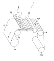
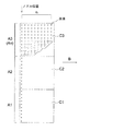
図1は、本発明に係る塗布方法が適用可能な塗布装置1の一例を示す概略図である。
FIG. 1 is a schematic view showing an example of a
ロール状に巻かれた長尺状の基材10は、図示しない駆動手段により巻き出しロール10aから矢印B方向に繰り出され搬送される。
The
長尺状の基材10は支持ロール12、14に支持されながら連続搬送され、塗布部2の塗布ユニット20に配設されたインクジェットヘッド21より塗布液が吐出されることにより、塗布液が基材10に塗布され塗膜10Aが形成される。塗布液が塗布された基材10は、乾燥部50を経由して巻き取りロール10bに巻き取られる。
The
また、塗布部2は、インクジェットヘッド201に塗布液を供給する塗布液供給機構(不図示)を含み構成される。
The
本実施の形態では、塗布ユニット20を、基材10が支持ロール12を通過した直後の、基材10が搬送方向に直線的に搬送される位置に、基材12の幅方向に塗布幅に対応して配設している。また、基材10とインクジェットヘッド21との間隙を安定に維持するために、インクジェットヘッド201の近傍に、基材10の塗布面の反対側に基材10を支持する支持部材(不図示)を設けることが好ましい。
In the present embodiment, the
また、塗布ユニット20を、基材10を挟み支持ロール12と対向する位置に、基材12の幅方向に塗布幅に対応して配設してもよい。この場合、塗布液はインクジェットヘッド21のノズルより支持ロール12のほぼ回転中心方向に吐出される。
Further, the
塗布ユニット20は、基材10の幅方向に複数配設されたインクジェットヘッド21を備え、塗布部2に固定され、インクジェットヘッド21は、連続搬送される基材10の搬送方向と直交する幅方向の、所定の位置に液滴を吐出する。即ち、塗布装置1は、所謂ライン型塗布装置と称されるものである。
The
インクジェットヘッド21の個数及び配列は、使用する塗布液、塗布条件、例えばインクジェットヘッド21の吐出幅及び基材10の塗布幅等、により適宜設定される。
The number and arrangement of the inkjet heads 21 are appropriately set depending on the coating liquid to be used and the coating conditions, for example, the ejection width of the
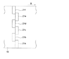
図2は、インクジェットヘッド21及び塗布液を吐出するノズル211の配列の例を示す図である。図2に示す例では、インクジェットヘッド21は、基材10の幅方向に配列された2列のノズル211(211a、211b)を有する。1列のノズル211a、211bは、それぞれノズルピッチPnで配置されている。またノズル211aと211bは、ノズルピッチPnの半ピッチ分、1/2Pn、互いにずらして配置されている。
FIG. 2 is a diagram illustrating an example of the arrangement of the
また、隣接するインクジェットヘッド21は、例えば、隣接する21aと21bの隣接するノズルのノズル間距離が前述の1/2Pnとなるように、千鳥配列されている。図3に、6つのインクジェットヘッド21a〜fを千鳥配列した例を示す。
Adjacent inkjet heads 21 are staggered so that, for example, the distance between adjacent nozzles of adjacent 21a and 21b is 1/2 Pn. FIG. 3 shows an example in which six
インクジェットヘッド21としては特に限定はなく、例えば発熱素子を有し、この発熱素子からの熱エネルギーにより塗布液の膜沸騰による急激な体積変化によりノズルから塗布液を吐出させるサーマルタイプのヘッドでもよいし、インク圧力室に圧電素子を備えた振動板を有しており、この振動板によるインク圧力室の圧力変化で塗布液を吐出させる剪断モード型(ピエゾ型)のヘッドであってもよい。
The
インクジェットヘッド21の側面には、インクジェットヘッド21の温度を検出する温度センサー23が設けられている(図4参照)。温度センサー23としては、サーミスタ等を用いることができる。
A
なお、本発明に係る基材10は種類に制限はなく、紙、プラスチックフィルム、金属シートなどを用いることができる。紙としては、例えばレジンコート紙、合成紙などが挙げられる。又、プラスチックフィルムとしては、ポリオレフィンフィルム(例えばポリエチレンフィルム、ポリプロピレンフィルムなど)、ポリエステルフィルム(例えば、ポリエチレンテレフタレートフィルム、ポリエチレン2,6−ナフタレートフィルムなど)、ポリアミドフィルム(例えば、ポリエーテルケトンフィルムなど)、セルロースアセテートフィルム(例えば、セルローストリアセテートフィルムなど)などが挙げられる。又、金属シートではアルミニウム板が代表的である。
The
また、用いる基材10の厚さ・幅についても、特に制限はないが、塗布幅は、1〜5mであることが好ましい。塗布幅が1m未満の場合、生産性向上を図るには塗布速度(CS)を上げる必要があるが、インクジェットヘッド21の吐出速度、即ち吐出量には制限があり、塗布速度の増加は制限される。また、5m超の場合、配列するインクジェットヘッド21の個数が多くなり、ノズル211と基材10の間隙の精度の確保等インクジェットヘッド21の保持が困難になり、大型で複雑な構造となりやすい。
Moreover, there is no restriction | limiting in particular also about the thickness and the width | variety of the
次に、本発明に係る塗布方法について説明する。 Next, the coating method according to the present invention will be described.
塗布装置1での塗布においては、インクジェットヘッド21のノズル211から吐出される塗布液の液滴の吐出量を検出し、その検出結果に基づき、ノズル211の個々の吐出と不吐出及び駆動電圧を制御することにより、前記吐出量が制御され、塗膜の膜厚の均一化が図られる。
In coating with the
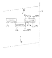
図4は、前記制御の構成を示すブロック図である。 FIG. 4 is a block diagram showing the configuration of the control.
液滴測定部7は、吐出された液滴の移動を検知する検知手段を有し、図4に示すように、液滴の吐出方向と略直交する方向で、且つ塗布ユニット20の近傍で、吐出された液滴が前記検知手段の視野に入る位置に配設される。前記検知手段としては、CCDカメラとストロボを同期させることで吐出液滴速度を測定するような手段でも良いし、レーザーを飛翔中の液滴に照射することで、飛翔液滴のサイズ、速度を測定するような手段でも良い。
The droplet measuring unit 7 includes a detecting unit that detects the movement of the discharged droplet, and as shown in FIG. 4, in a direction substantially orthogonal to the droplet discharging direction and in the vicinity of the
ここで、ノズル211からの液滴の吐出量と吐出速度は相関があることが知られている。従って、前記塗布での液滴の吐出量は、吐出速度を測定し、液滴の吐出量と吐出速度の相関データを参照することにより求めることができる。
Here, it is known that there is a correlation between the discharge amount of the droplets from the
前記液滴の吐出量と吐出速度の相関データは、塗布位置外に、即ちオフラインに設けられた吐出データ作成部6で作成される。 The correlation data between the droplet ejection amount and the ejection speed is created by the ejection data creation unit 6 provided outside the application position, that is, off-line.
吐出データ作成部6では、オフラインにて全ノズルから所定数(例えば、100000発)の液滴吐出を行い、その時の吐出量(吐出質量)と吐出回数を測定し、1滴当りの液滴量(液滴質量)を算出する。同時に、吐出速度と吐出時間を測定し、吐出速度と単位時間当たりの吐出回数と吐出量を算出する。これにより、吐出速度と単位時間当たりの吐出量が関連付けられる。次に、液滴吐出の駆動条件(駆動電圧)を変更して、上記と同様に測定及び算出を行うことで、液滴吐出の駆動条件変更した場合の吐出速度と単位時間当たりの吐出量が関連付けられる。このようにして、吐出速度と単位時間当たりの液滴の吐出量の相関データが作成される。 The discharge data creation unit 6 discharges a predetermined number of droplets (for example, 100,000 shots) from all nozzles offline, measures the discharge amount (discharge mass) and the number of discharges at that time, and the droplet amount per droplet (Droplet mass) is calculated. At the same time, the discharge speed and the discharge time are measured, and the discharge speed, the number of discharges per unit time, and the discharge amount are calculated. Thereby, the discharge speed and the discharge amount per unit time are associated. Next, by changing the driving condition (driving voltage) of the droplet discharge and performing measurement and calculation in the same manner as described above, the discharge speed and the discharge amount per unit time when the driving condition of the droplet discharge is changed Associated. In this manner, correlation data between the discharge speed and the droplet discharge amount per unit time is created.
前記吐出速度は、吐出データ作成部6に設けられた、液滴測定部7と同様な液滴測定手段(不図示)で、インクジェットヘッド21のノズル211から吐出された液滴位置を所定時間の間隔(例えば、1μs間隔)で測定し、その結果に基づく時間と距離との関係から算出される。
The discharge speed is determined by measuring the position of a droplet discharged from the
次に、塗膜の膜厚を均一にするための塗布方法について説明する。 Next, an application method for making the film thickness of the coating film uniform will be described.
前述のように、ノズル211からの液滴の吐出量と吐出速度は相関があることが知られている。従って、各ノズル211から吐出される液滴の吐出速度分布は、吐出量の分布と相関関係があることになる。吐出量の分布は、基材に塗布され濡れ広がった後の塗膜の膜厚分布と相関関係があることから、前記吐出速度分布も前記膜厚分布と相関関係があるといえる。
As described above, it is known that there is a correlation between the discharge amount of the droplets from the
ここで、塗膜の膜厚の均一化は、液滴の吐出量のばらつきを抑制することにより行うことができる。液滴の吐出量のばらつきを抑制することは、吐出速度のばらつきを抑制することでもある。 Here, the film thickness of the coating film can be made uniform by suppressing variations in the droplet discharge amount. Suppressing variations in the discharge amount of droplets also means suppressing variations in ejection speed.
塗布においての各ノズル211からの吐出量の検出は、各ノズル211からの液滴の吐出速度を測定し、上記の吐出データ作成部6で作成された相関データと照合することにより求めることで行われる(検出ステップ)。
The detection of the discharge amount from each
詳しくは、液滴測定部7は、インクジェットヘッド21のノズル211から吐出された液滴位置を所定時間の間隔(例えば、1μs間隔)で測定し、その測定データを吐出データ処理部5に送る。吐出データ処理部5は前記測定データ基づき時間と距離との関係から吐出速度を算出する。更に、吐出データ処理部5は、上記の吐出データ作成部6で作成された相関データと照合することにより吐出量を算出する。
Specifically, the droplet measuring unit 7 measures the positions of the droplets ejected from the
液滴の吐出量のばらつきの抑制は、次のようにして行われる。 Suppression of variations in the discharge amount of droplets is performed as follows.
先ず、ノズル211を所定数(5〜30個)に区切り分割し、1ノズルユニットとし、領域Aとする。前記分割の数は、インクジェットヘッド21内のノズル211の個数が割り切れる数とする。また、1つのインクジェットヘッド21を1ノズルユニットとし、領域Aとしてもよい。領域Aは、ノズルの駆動電圧を一括して変更できる区切りである。
First, the
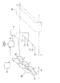
図5は、ノズル211を10個毎に分割し領域Aとした例であり、各領域AをA1〜A3とした。分割数、領域数はこれに限定されるものではない。図5中、矢印Bは基材搬送方向である。
FIG. 5 shows an example in which the
次に、ノズル211の基準駆動電圧での、各領域A(A1〜A3)のノズル211の液滴の吐出速度を測定し、領域A1〜A3毎の平均吐出速度を算出する。そして、その平均吐出速度の最も低い領域、即ち吐出量が最も少ない領域を基準領域に設定する。例えば、図5の領域A1が平均吐出速度が最も低い領域であれば、領域A1を基準領域に設定する。
Next, the droplet ejection speed of the
次に、領域A1の平均吐出速度が予め決められている最適吐出速度(例えば、5m/s)になるように、領域A1のヘッドの駆動電圧を調整する。そして、その時の領域A1での吐出量(A1吐出量)を算出する。これを基準吐出量とする。 Next, the driving voltage of the head in the area A1 is adjusted so that the average discharge speed in the area A1 becomes a predetermined optimum discharge speed (for example, 5 m / s). And the discharge amount (A1 discharge amount) in the area | region A1 at that time is calculated. This is the reference discharge amount.
次に、他の領域A(A2、A3)の吐出量(A2、A3吐出量)が基準吐出量(A1吐出量)と同じになるようにするために、領域A2、A3の吐出量の低下量を吐出データ処理部5で算出する。
Next, in order to make the discharge amount (A2, A3 discharge amount) of the other regions A (A2, A3) equal to the reference discharge amount (A1 discharge amount), the discharge amount of the regions A2, A3 is decreased. The amount is calculated by the discharge
前記低下量を基に、膜厚分布を均一にするための制御が行われる。 Control for making the film thickness distribution uniform is performed based on the amount of decrease.
前述の、所定数のノズル数毎に分割し、低下量を算出した領域Aにおいて、n回連続して吐出を行えば、基材搬送方向にn個の液滴が加算されることになり、n回の吐出を1単位とした場合には、単位に区切った塗布エリアC(図5ではC1〜C3)には、ノズル数An×n個の液滴が存在することになる。図5に示す例では、An=10、n=10となり、1つの塗布エリアCは、100個の液滴で構成されることになる。吐出回数n、特に限定されるものではないが、ノズル数Anと同等であることが好ましい。 In the above-described region A where the number of nozzles is divided for each predetermined number and the amount of decrease is calculated, if droplets are continuously ejected n times, n droplets are added in the substrate transport direction. When n discharges are defined as one unit, the number of nozzles An × n droplets is present in the coating area C (C1 to C3 in FIG. 5) divided into units. In the example shown in FIG. 5, An = 10 and n = 10, and one application area C is composed of 100 droplets. The number of discharges n is not particularly limited, but is preferably equal to the number of nozzles An.
前述の、低下量の制御は、各エリアを対象に行われる。制御は、上記で算出した低下量になるように、各エリアCから液滴を間引くことで行われる。例えば、エリアCが図5に示すように、10×10(=100)個の液滴で構成されているならば、液滴を1個間引くことで、1%低下させることができる。この時、液滴の間引き方に決まりはなくエリア内であればランダムに間引いて良い。 The above-described reduction amount control is performed for each area. The control is performed by thinning out the droplets from each area C so that the amount of decrease calculated above is obtained. For example, if the area C is composed of 10 × 10 (= 100) droplets as shown in FIG. 5, it can be reduced by 1% by thinning out one droplet. At this time, the method of thinning out the droplets is not determined and may be thinned out randomly within the area.
液滴の間引きのパターン、即ち吐出パターンは、吐出データ処理部で算出、設定される。設定された吐出パターンは制御部4に送られ、制御部4は、ノズル211の吐出、不吐出の制御を行う。液滴を間引いた箇所は、あるタイミングでノズル211から液滴が吐出されないことになる。
The droplet thinning pattern, that is, the ejection pattern, is calculated and set by the ejection data processing unit. The set ejection pattern is sent to the control unit 4, and the control unit 4 controls ejection and non-ejection of the
図5の例では、エリアC2、C3の液滴を算出した低下量になるように液滴を間引き、エリアC2、C3の吐出量が、C1の吐出量と同じになるように調整される。 In the example of FIG. 5, the droplets are thinned out so that the calculated drop amounts of the areas C2 and C3 are reduced, and the discharge amounts of the areas C2 and C3 are adjusted to be the same as the discharge amount of C1.
連続しての塗布中での、不吐出のノズル211の発生、吐出が変化したノズル211の発生は、各インクジェットヘッド21のノズル211から吐出された液滴の吐出速度をオンラインで測定することで検知することができる。これにより、吐出量の変化を算出して、吐出量を検出することができる。
The generation of
前記吐出量の検出結果に基づき、各ノズル211の個々の吐出と不吐出の制御と、前記駆動電圧を制御し、インクジェットヘッド21から基材10に前記塗布液の液滴を吐出することにより塗膜の形成は行われる(形成ステップ)。
Based on the detection result of the discharge amount, control of individual discharge and non-discharge of each
また、温度センサー23でインクジェットヘッド21の温度をモニターすることで、ヘッド温度変化を感知すると、自動的に吐出速度を測定するようにすることもできる。また、吐出開始直度の液滴の軌道を記憶しておくことで経時での液滴の曲がりや未吐出などが生じた場合、それを感知して自動で吐出液滴速度を測定することもできる。
In addition, by monitoring the temperature of the
前記吐出量の検出において、吐出中の一部のノズル211に故障による吐出量の低下または不吐出を検出した時は、前述のエリアC内の前記一部のノズル211の、基材10の幅手方向に隣接する、または周囲のノズル211の不吐出の頻度を制御し減少させることにより、エリアC内の吐出量の低下を防止する。
In the detection of the discharge amount, when a decrease or non-discharge of the discharge amount due to a failure is detected in a part of the
また、前記吐出量の検出において、ノズル211の駆動電圧が一括して変更できる所定数(領域A)のノズル211内に、故障による不吐出のノズル211が複数発生した場合には、前記駆動電圧を高くすることの要否の判定を行い、要の場合には前記駆動電圧の制御を行う。前記要の場合とは、吐出量ゼロのノズル211の、周囲のノズル211の不吐出の頻度を変更しても、吐出量が回復できない場合である。
Further, in the detection of the discharge amount, when a plurality of
前記吐出量の検出において、不吐出のノズル211がない場合には、吐出量の調整に際しての各ノズル211の吐出と不吐出の制御は、全ノズル211の不吐出の頻度を60%未満とすることが好ましい。60%以上では、膜厚分布の劣化、膜厚低下が生じる恐れがある。60%未満であれば、吐出量の調整に適合した頻度とすれば良く、特に限定されるものではない。
When there is no
塗布装置1は、全ノズルユニットが同一品で交換可能に構成され、更にノズル211からの吐出量が測定済みのノズルユニットが1つ以上、交換用予備ユニットとして、設けられている。前記吐出量の検出結果から、塗布中のユニットが、各ノズル211の個々の吐出と不吐出の制御と、記駆動電圧の制御では、均一な膜厚の塗膜ができないと判定、または、均一な膜厚の塗膜が不可能となることが近いと判定された場合には、前記交換用予備ユニットに自動的に交換、またはユニット交換の警告が表示手段等で操作者に伝達される。これにより、塗布不良の軽減を図ることができる。
The
前記塗布においては、前記基材の連続搬送の搬送速度(CS)は、300m/min未満であることが好ましい。300m/min以上では、塗膜を形成する際に、インクジェットヘッド21の駆動周波数限界を超えてしまう恐れがあり、また同伴空気による影響が大きく、ミストなどがノズルに付着することで液滴の吐出方向が曲がったり、不吐出になったりして膜厚分布を劣化させる。300m/min未満であれば、塗布の生産仕様、目的にあった搬送速度に設定すれば良く、特に限定されるものではない。
In the said application | coating, it is preferable that the conveyance speed (CS) of the continuous conveyance of the said base material is less than 300 m / min. If it is 300 m / min or more, when the coating film is formed, the drive frequency limit of the
上記のように、連続塗布中での、各インクジェットヘッド21の故障やヘッド温度変化による吐出量の変化を、ノズル211から吐出された液滴の吐出速度をオンラインで測定することにより、検出する。その検出結果に基づいて、吐出変化したノズル211の周囲のノズル211の不吐出の頻度を調整することで、連続的に搬送する被塗布物を停止させることなく塗膜の膜厚を均一に塗布することが可能となる。これにより、塗膜形成の生産性の向上を図ることができる。
As described above, a change in ejection amount due to a failure of each
また、上記により、塗布直後の塗布面を目視観察した際に、塗布液がレベリングしてスジとして観察できないようなレベルの塗布故障でさえも検出して、それを基材搬送中に補正することで、塗膜品質を劣化させるような塗布故障を未然に防止することができる。 In addition, according to the above, even when a coating surface immediately after coating is visually observed, even a coating failure at a level where the coating solution is leveled and cannot be observed as a streak is detected and corrected during conveyance of the substrate. Thus, it is possible to prevent a coating failure that degrades the coating film quality.
また、塗膜の膜厚を均一にするために、あるタイミングで不吐出とするノズル211をランダムに切り替えることで、ノズル211の吐出寿命を延長することが可能となる。
Moreover, in order to make the film thickness of the coating film uniform, it is possible to extend the discharge life of the
更に、本発明の塗布方法では塗膜の表面粗さRa値を0.1μm以下に抑制することができる。そのため、光学薄膜などの表面粗さが大きいと品質に大きな影響を与えてしまう商品の製造を考えた場合には、本発明の塗布方法は、効果的である。 Furthermore, in the coating method of the present invention, the surface roughness Ra value of the coating film can be suppressed to 0.1 μm or less. Therefore, the coating method of the present invention is effective when considering the manufacture of products that have a large effect on quality when the surface roughness of an optical thin film or the like is large.
<実施例1>
図1及び図4に示す塗布装置1を用い、本発明の塗布方法で塗布を行い評価した。
<Example 1>
Using the
塗布装置1は、6つのインクジェットヘッド21を千鳥に配置し、それと対向するように6台のCCDカメラを用いて、ヘッド21から吐出された液滴を観察できるようにした。塗布に用いた基材(被塗布物)10としては長さ3000m、幅1m、厚さ100μmのPET基材を用いた。
In the
塗布液としては、エチレングリコールモノブチルエーテルアセテートを80%、固形分を20%の比率で希釈した溶媒に顔料及び分散剤を投入し、ハイスピードミキサー等で均一になるまで攪拌後、得られたミルベースを横型エンドミルで約1時間分散したものを用いた。その塗布液を各ヘッドに充填し、その後、ノズル穴内部の汚れやゴミを取り除く目的で強制排出を行い、その後、ヘッド21のノズル面に付着した汚れを綿棒で清掃し射出開始できるように準備をした。
As a coating solution, a pigment and a dispersant were added to a solvent diluted with ethylene glycol monobutyl ether acetate at a ratio of 80% and solid content at a ratio of 20%, and after stirring with a high speed mixer or the like, the resulting mill base was stirred. Was dispersed with a horizontal end mill for about 1 hour. The coating liquid is filled into each head, and then forcibly discharged for the purpose of removing dirt and dust inside the nozzle hole. After that, the dirt adhering to the nozzle surface of the
連続射出開始前に、ヘッドの駆動電圧を10Vに設定し液滴の吐出速度の測定を行い、その後、各ヘッド21の吐出速度の平均値が5m/sになるように各ヘッド21に印加する駆動電圧を微調整した。そして、各ノズル211から射出される吐出速度データを基に速度分布を算出した。次に、この速度分布を、ノズル211の10個毎の領域に区切り、その平均値を算出し、分布が最も低い部分を基準領域として他の測定位置での分布データを基準値に合わせるようにするために各測定位置での低下量を決定した。次に、液滴数10×10の塗布エリアCを作成し、そこから、算出した低下量に相当する液滴を間引くことで調整を行った。
Prior to the start of continuous ejection, the head drive voltage is set to 10 V and the droplet ejection speed is measured, and then applied to each
上記の方法で、3000mの長尺の連続塗布を行った。この時、基材の搬送速度を30m/minとした。 3000 m long continuous coating was performed by the above method. At this time, the conveyance speed of the base material was 30 m / min.
連続射出中は、インクジェットヘッド21の温度をモニターし温度変化を感知すれば液滴速度を再測定し上記記載の方法で液滴の間引き方の補正をオンラインで行った。また、ヘッド21から射出される液滴の曲がりや未射出を感知することで液滴速度を再測定し間引きかたの補正をオンラインで行った。
During continuous ejection, the temperature of the
膜厚分布の評価方法としては、連続射出開始直後の幅手方向の膜厚分布のバラツキと連続射出直前での幅手方向の膜厚分布のバラツキを比較した。この時、バラツキには標準偏差を用いた。また、測定は幅手方向に対してランダムに20点測定した。 As a method for evaluating the film thickness distribution, the variation in the film thickness distribution in the width direction immediately after the start of continuous injection was compared with the variation in the film thickness distribution in the width direction immediately before the continuous injection. At this time, the standard deviation was used for variation. In addition, 20 points were measured at random in the width direction.
塗布膜の表面粗さ測定には、原子間力顕微鏡(SPI−3800N AFM;セイコーインスツルメンツ(株)製)を用いて評価した。塗膜表面において、ランダムに1μm×1μmの面積における測定を行い、合計10カ所における平均表面粗さRaの平均値を求めた。 The surface roughness of the coating film was measured using an atomic force microscope (SPI-3800N AFM; manufactured by Seiko Instruments Inc.). On the surface of the coating film, measurement was randomly performed in an area of 1 μm × 1 μm, and an average value of average surface roughness Ra at a total of 10 locations was obtained.
<比較例1>
実施例1と同じ塗布装置1を用い、吐出制御の方法を変えて評価した。
<Comparative Example 1>
The
長尺塗布中にスジが発生した場合、基材の搬送をいったん停止した後、塗膜表面の膜厚分布を原子間力顕微鏡(SPI−3800N AFM;セイコーインスツルメンツ(株)製)を用いて測定した。その後、そのデータを基にノズル211から射出される液滴のパターンを修正して、それをヘッド21にフィードバックさせて再び塗布を開始する塗布方法で塗布を行った。再吐出の際には、ヘッド洗浄などの一連の操作を行った後に塗布開始をした。
If streaks occur during long coating, the transport of the substrate is temporarily stopped, and the film thickness distribution on the coating surface is measured using an atomic force microscope (SPI-3800N AFM; manufactured by Seiko Instruments Inc.). did. Thereafter, the pattern of droplets ejected from the
表1に、実施例1と比較例1の評価結果を示す。 Table 1 shows the evaluation results of Example 1 and Comparative Example 1.

表1に示すように、本発明に係る塗布方法の有効性が確認された。 As shown in Table 1, the effectiveness of the coating method according to the present invention was confirmed.
1 塗布装置
2 塗布部
4 制御部
5 吐出データ処理部
6 吐出データ作成部
7 液滴測定部
10 基材
12、14 支持ロール
20 塗布ユニット
21 インクジェットヘッド
211 ノズル
50 乾燥部
A 領域
C 塗布エリア
DESCRIPTION OF
Claims (9)
前記ノズルから吐出される、前記液滴の吐出量を検出する検出ステップと、
前記吐出量の検出結果に基づき、各ノズルの個々の吐出と不吐出の制御と、前記駆動電圧の制御で吐出量を制御し、前記インクジェットヘッドから前記基材に前記塗布液の液滴を吐出して塗膜を形成する形成ステップと、
を有することを特徴とする塗布方法。 A long base material that is continuously transported is provided with a plurality of nozzles arranged in a width direction orthogonal to the transport direction of the base material, and the nozzles are adjacent to each other whose drive voltage can be changed in a lump. An inkjet head arranged and fixed in the width direction orthogonal to the transport direction of the base material, which is divided for each predetermined number of nozzles and can be individually switched between ejection and non-ejection of droplets. In the coating method of forming a coating film with a uniform film thickness by discharging droplets of the coating liquid using,
A detection step of detecting a discharge amount of the droplets discharged from the nozzle;
Based on the detection result of the discharge amount, the discharge amount is controlled by controlling the discharge and non-discharge of each nozzle and the drive voltage, and the droplets of the coating liquid are discharged from the inkjet head onto the substrate. Forming step to form a coating film,
A coating method characterized by comprising:
Priority Applications (1)
| Application Number | Priority Date | Filing Date | Title |
|---|---|---|---|
| JP2008245506A JP2010075813A (en) | 2008-09-25 | 2008-09-25 | Coating method |
Applications Claiming Priority (1)
| Application Number | Priority Date | Filing Date | Title |
|---|---|---|---|
| JP2008245506A JP2010075813A (en) | 2008-09-25 | 2008-09-25 | Coating method |
Publications (1)
| Publication Number | Publication Date |
|---|---|
| JP2010075813A true JP2010075813A (en) | 2010-04-08 |
Family
ID=42206889
Family Applications (1)
| Application Number | Title | Priority Date | Filing Date |
|---|---|---|---|
| JP2008245506A Pending JP2010075813A (en) | 2008-09-25 | 2008-09-25 | Coating method |
Country Status (1)
| Country | Link |
|---|---|
| JP (1) | JP2010075813A (en) |
Cited By (4)
| Publication number | Priority date | Publication date | Assignee | Title |
|---|---|---|---|---|
| JP2012073252A (en) * | 2010-09-27 | 2012-04-12 | Cordis Corp | Quantitation and analysis of droplet ejected from inkjet device |
| CN109070124A (en) * | 2016-04-05 | 2018-12-21 | Sat(金属铝壳技术)有限责任公司 | Systems and processes for coating profiles |
| CN113019841A (en) * | 2021-03-04 | 2021-06-25 | 业成科技(成都)有限公司 | Water gel coating method and multi-point piezoelectric type spraying device thereof |
| JP2022008798A (en) * | 2015-12-07 | 2022-01-14 | カティーバ, インコーポレイテッド | Techniques for manufacturing thin films with improved homogeneity and print speed |
-
2008
- 2008-09-25 JP JP2008245506A patent/JP2010075813A/en active Pending
Cited By (7)
| Publication number | Priority date | Publication date | Assignee | Title |
|---|---|---|---|---|
| JP2012073252A (en) * | 2010-09-27 | 2012-04-12 | Cordis Corp | Quantitation and analysis of droplet ejected from inkjet device |
| JP2022008798A (en) * | 2015-12-07 | 2022-01-14 | カティーバ, インコーポレイテッド | Techniques for manufacturing thin films with improved homogeneity and print speed |
| JP7278640B2 (en) | 2015-12-07 | 2023-05-22 | カティーバ, インコーポレイテッド | Techniques for producing thin films with improved uniformity and print speed |
| US12059910B2 (en) | 2015-12-07 | 2024-08-13 | Kateeva, Inc. | Techniques for manufacturing thin films with improved homogeneity and print speed |
| CN109070124A (en) * | 2016-04-05 | 2018-12-21 | Sat(金属铝壳技术)有限责任公司 | Systems and processes for coating profiles |
| CN113019841A (en) * | 2021-03-04 | 2021-06-25 | 业成科技(成都)有限公司 | Water gel coating method and multi-point piezoelectric type spraying device thereof |
| CN113019841B (en) * | 2021-03-04 | 2023-03-17 | 业成科技(成都)有限公司 | Water gel coating method and multi-point piezoelectric type spraying device thereof |
Similar Documents
| Publication | Publication Date | Title |
|---|---|---|
| US8449106B2 (en) | Image recording device and image recording method | |
| US8708480B2 (en) | Recording apparatus | |
| CN102815090A (en) | Printing apparatus and control method thereof | |
| JP2010075813A (en) | Coating method | |
| JP2009112954A (en) | Coating method | |
| JP6977777B2 (en) | Inkjet recording device | |
| JPWO2008149652A1 (en) | Coating device | |
| JP4747829B2 (en) | Coating film forming apparatus and coating film forming method | |
| JP2020082413A (en) | Head cleaning device, ink jet image formation apparatus and cleaning method | |
| JP2014162052A (en) | Liquid jetting device | |
| JP2006281176A (en) | Thin film forming apparatus | |
| JP2006263536A (en) | Coating apparatus | |
| JP5186967B2 (en) | Application method | |
| JP4730069B2 (en) | Coating film forming device | |
| JP2006326456A (en) | Coating method | |
| EP4044775B1 (en) | Film forming method and film forming device | |
| JP2006239565A (en) | Coating method | |
| JP2004313895A (en) | Coating applicator and coating application method | |
| WO2019016956A1 (en) | Inkjet recording device | |
| JP4923820B2 (en) | Functional material coating apparatus and functional material coating method | |
| CN114919309B (en) | Film forming method and film forming apparatus | |
| JP2007301493A (en) | Coating method and coating apparatus | |
| JP2008155139A (en) | Coating liquid film forming method | |
| JP2025176533A (en) | Inkjet recording apparatus, method for suppressing ejection defects, and program | |
| JP2004337799A (en) | Coating apparatus and method for applying coating liquid |