JP4920866B2 - System for spectral multiplexing and rendering of source images and spectral demultiplexing to form animated source images - Google Patents
System for spectral multiplexing and rendering of source images and spectral demultiplexing to form animated source images Download PDFInfo
- Publication number
- JP4920866B2 JP4920866B2 JP2003344714A JP2003344714A JP4920866B2 JP 4920866 B2 JP4920866 B2 JP 4920866B2 JP 2003344714 A JP2003344714 A JP 2003344714A JP 2003344714 A JP2003344714 A JP 2003344714A JP 4920866 B2 JP4920866 B2 JP 4920866B2
- Authority
- JP
- Japan
- Prior art keywords
- image
- source
- composite image
- dye
- spectral
- Prior art date
- Legal status (The legal status is an assumption and is not a legal conclusion. Google has not performed a legal analysis and makes no representation as to the accuracy of the status listed.)
- Expired - Fee Related
Links
Images


Classifications
-
- B—PERFORMING OPERATIONS; TRANSPORTING
- B44—DECORATIVE ARTS
- B44F—SPECIAL DESIGNS OR PICTURES
- B44F1/00—Designs or pictures characterised by special or unusual light effects
- B44F1/08—Designs or pictures characterised by special or unusual light effects characterised by colour effects
- B44F1/10—Changing, amusing, or secret pictures
-
- G—PHYSICS
- G02—OPTICS
- G02B—OPTICAL ELEMENTS, SYSTEMS OR APPARATUS
- G02B27/00—Optical systems or apparatus not provided for by any of the groups G02B1/00 - G02B26/00, G02B30/00
- G02B27/02—Viewing or reading apparatus
- G02B27/06—Viewing or reading apparatus with moving picture effect
Landscapes
- Physics & Mathematics (AREA)
- General Physics & Mathematics (AREA)
- Optics & Photonics (AREA)
- Facsimile Image Signal Circuits (AREA)
- Processing Or Creating Images (AREA)
Description
本発明は、複合画像を供給するために複数のソース画像をスペクトル多重化し、その複合画像をレンダリングし、1つ又はそれ以上のソース画像を回復するためにこのような複合画像を逆多重化するための1つ又は複数のシステムに関する。 The present invention spectrally multiplexes a plurality of source images to provide a composite image, renders the composite image, and demultiplexes such composite images to recover one or more source images. One or more systems for
スペクトル多重化とは、本明細書で使用される時には、複合画像内に複数のソース画像を符号化する処理を意味する。複合画像レンダリングとは、複合画像を物理的な形態にレンダリングする処理をいう。スペクトル逆多重化とは、レンダリングされた複合画像をソース画像を見せるために予め選択された狭帯域発光体に曝すことにより、回復されたソース画像が複合画像から又は複合画像内で区別可能にされるように、符号化されたソース画像のうちの少なくとも1つをレンダリングされた複合画像から回復する処理を意味する。 Spectral multiplexing, as used herein, refers to the process of encoding multiple source images within a composite image. Composite image rendering refers to a process of rendering a composite image into a physical form. Spectral demultiplexing means that the recovered source image can be distinguished from or within the composite image by exposing the rendered composite image to a preselected narrowband illuminator to show the source image. As such, it means the process of recovering at least one of the encoded source images from the rendered composite image.
従って、本発明は、複数のソース画像をスペクトル符号化して、このスペクトル符号化された複数のソース画像を複合画像内に形成し、複合画像を物理的な形態にレンダリングし、又は、回復されたソース画像が区別可能にされるように、レンダリングされた複合画像から少なくとも1つの符号化されたソース画像を回復するための方法及び装置に関する。例えば、レンダリングされた複合画像が、ソース画像が符号化された対象である狭帯域発光体の1つにより照明を受ける時、ソース画像は、観察者により視覚的に検知可能になる。所定の色素と特に相互作用するように設計された発光体は、補完的であると言われ、また逆も成り立つ。 Thus, the present invention spectrally encodes a plurality of source images, forms the plurality of spectrally encoded source images in a composite image, and renders or recovers the composite image into a physical form. The present invention relates to a method and apparatus for recovering at least one encoded source image from a rendered composite image so that the source image is distinguishable. For example, when the rendered composite image is illuminated by one of the narrowband illuminators to which the source image is encoded, the source image becomes visually detectable by the viewer. Phosphors that are specifically designed to interact with a given dye are said to be complementary and vice versa.
各ソース画像は、各ソース画像ピクセルを代表する値を、複数の色素画像平面のうちの1つ又はそれ以上における対応するピクセル値にマップすることにより、スペクトル的に符号化される。想定される符号化は、その最も簡単な形においては、単色性分離画像への各ソース画像の変換を含むことができ、この単色分離画像は、その後、複合画像内の対応する色素画像平面に直接マップされる。それにより、複数のソース画像を複合画像内の対応する複数の色素画像平面にマップすることができる。 Each source image is spectrally encoded by mapping a value representative of each source image pixel to a corresponding pixel value in one or more of the plurality of dye image planes. The envisioned encoding, in its simplest form, can include the transformation of each source image into a monochromatic separation image, which is then converted into the corresponding dye image plane in the composite image. It is mapped directly. Thereby, a plurality of source images can be mapped to a corresponding plurality of dye image planes in the composite image.
複数の単色分離画像は、複合画像内で組み合わされるように設計されており、この複合画像は、次に、基体上に堆積される1つ又はそれ以上の予め選択された色素の量を制御することになる。1つの可能な例においては、各色素は、複合画像のそれぞれの色素画像平面に割り当てられ、それぞれの色素画像平面内の色素値は、レンダリングされた複合画像に堆積された色素の相対量を表す。
複数の色素画像平面から成る複合画像は、複合画像ファイルとして記憶又は送信することができる。次に、識別された色素又は色素のアレーを使用して基体上の複合画像をレンダリングする命令と共に複合画像ファイルをレンダリング装置に供給することにより、複合画像を物理的に実現することができる。従って、レンダリング装置の適切な一実施形態は、デジタルカラー電子写真プリンタを含む。
The plurality of single color separation images are designed to be combined in a composite image that in turn controls the amount of one or more preselected dyes deposited on the substrate. It will be. In one possible example, each dye is assigned to a respective dye image plane of the composite image, and the dye value in each dye image plane represents the relative amount of dye deposited in the rendered composite image. .
A composite image consisting of a plurality of dye image planes can be stored or transmitted as a composite image file. The composite image can then be physically realized by supplying a composite image file to the rendering device with instructions to render the composite image on the substrate using the identified dye or array of dyes. Accordingly, one suitable embodiment of a rendering device includes a digital color electrophotographic printer.
各ソース画像のマッピングは、複合画像の構成、レンダリング、又は逆多重化に及ぼす以下のもの、すなわち、(a)色素/発光体相互作用に対する人間の視覚的応答の三色色度、(b)色素が基体上で結合された時に複数の色素の相互作用を特によく表すスペクトル特性のような、複合画像をレンダリングするために選択された色素のスペクトル特性、及び(c)ソース画像を回復するためにソース画像を照明するのに使用されることになる狭帯域発光体のスペクトル特性のうちの1つ又はそれ以上の影響を補償するための本明細書で説明する判断結果に従って実行することができる。 Each source image mapping has the following effects on the composition, rendering, or demultiplexing of the composite image: (a) the trichromaticity of the human visual response to the dye / emitter interaction, (b) the dye To recover the source image, and (c) the spectral characteristics of the dye selected to render the composite image, such as the spectral characteristics that are particularly well representative of the interaction of multiple dyes when bound on the substrate. It can be performed according to the determinations described herein to compensate for the effect of one or more of the spectral characteristics of the narrow band emitter that will be used to illuminate the source image.
ものを見る普通の照明の下では、目は、反射率が最も高い白紙に通常相当する白色点に適応し、異なる色は、異なる色素の組み合わせで作られたプリントに対して目によって見ることができる。しかし、CRTモニタ単一電子銃により励起された蛍光体から得られた照明のような比較的狭い帯域の照明の下では、目は、色を区別することができない。従って、狭帯域照明で見た画像は、グレーレベルの変化のみで色度がほとんどないか又は全くないように見える。複数の色素の各々の吸収特性は、異なるスペクトル帯域で異なるので、一連の異なる狭帯域照明を受ける時の各色素のそれぞれの反射率(又は、密度)はまた、グレーレベルが変化するように見えることになる。 Under normal lighting to see things, the eye adapts to a white point, usually equivalent to a white paper with the highest reflectivity, and different colors can be seen by the eye against prints made with different dye combinations. it can. However, under relatively narrow band illumination such as that obtained from a phosphor excited by a CRT monitor single electron gun, the eye cannot distinguish colors. Thus, an image viewed with narrowband illumination appears to have little or no chromaticity with only gray level changes. Since the absorption characteristics of each of the multiple dyes are different in different spectral bands, the respective reflectivity (or density) of each dye when subjected to a series of different narrowband illuminations also appears to change in gray level. It will be.
本発明は、従って、特定の狭帯域発光体とその対応する(補間的)色素(特に、一般的に印刷に使用される色素)との間の相互作用、及び、狭帯域スペクトルパワー分布を有する発光体で照明された画像を目が検知する方法を探求するものである。本明細書で説明する方法は、任意の数の発光体及び色素に応用されるように一般化することができ、単純化のために、本発明は、カラー印刷用途で一般的に使用されるシアン、マゼンタ、黄色、及び黒色の色素、及び、CRTベースの光源により一般的に発生する狭帯域の赤色発光体、緑色発光体、及び青色発光体と関連させて説明する。すなわち、本明細書は、「CMYK」原色のような色素のアレーに従って符号化された単色及びカラーソース画像の処理に関するものである。しかし、本発明のスペクトル多重化において使用される代替スペクトルスキームが存在することは、当業者には明らかであると思われる。代替案には、「RGB」原色、又は橙色及び緑色のような高忠実度色素を使用するシステムのような、カラー表現に対して「CMYK」以外の原色色素を使用するカラーシステムが含まれるであろう。更に別の代替案には、紫外線又は赤外線光源から発生する発光体に応答する狭帯域色素に対して符号化されたソース画像のような、異なる種類の多重スペクトルデータを処理するシステムにおいて本発明を使用することである。 The present invention thus has an interaction between a specific narrowband illuminant and its corresponding (interpolative) dye (especially a dye commonly used for printing) and a narrowband spectral power distribution. The present invention seeks a method in which an eye detects an image illuminated with a light emitter. The methods described herein can be generalized to apply to any number of illuminants and dyes, and for simplicity, the invention is commonly used in color printing applications. Cyan, magenta, yellow, and black pigments and the narrow-band red, green, and blue emitters typically generated by CRT-based light sources are described. That is, this specification relates to the processing of monochromatic and color source images encoded according to an array of dyes such as the “CMYK” primaries. However, it will be apparent to those skilled in the art that there are alternative spectral schemes used in the spectral multiplexing of the present invention. Alternatives include color systems that use primary colors other than “CMYK” for color representation, such as systems that use “RGB” primaries or high fidelity dyes such as orange and green. I will. Yet another alternative is to use the present invention in a system that processes different types of multispectral data, such as source images encoded for narrowband dyes responsive to illuminants generated from ultraviolet or infrared light sources. Is to use.
本発明は、複合画像内に符号化された少なくとも1つのソース画像の多重化又は逆多重化に関するので、複合画像は、スペクトル多重化された(SM)画像平面に形成することができる。この平面は、任意の数の異なるピクセルパターンを有することができ、その主な特徴は、平面がスペクトル的に多重化されることである。一般に、「SM」平面の各位置では、1つ又はそれ以上のスペクトル成分を有するピクセル値が存在することができ、どのスペクトル成分が存在するかは、ソース画像平面の1つにおける対応するピクセルのグレーレベルに依存する(本発明はまた、各ピクセルが1つよりも多いソース画像平面からのカラー分離画像データを表すカラー値を含む「SM」平面に応用することができる)。 Since the invention relates to the multiplexing or demultiplexing of at least one source image encoded in a composite image, the composite image can be formed in a spectrally multiplexed (SM) image plane. This plane can have any number of different pixel patterns, the main feature of which is that the plane is spectrally multiplexed. In general, at each location in the “SM” plane, there may be a pixel value having one or more spectral components, and which spectral component is present depends on the corresponding pixel in one of the source image planes. Depends on the gray level (the present invention can also be applied to the “SM” plane, where each pixel contains color values representing color separation image data from more than one source image plane).
本発明の一般的理論は、プリンタのようなカラーハードコピー出力装置の形態のレンダリング装置、及び、従来のカラー画像化で使用されるものと類似の技術用語を使用する数学的フレームワークと関連させて理解することができる。M個の色素を使用するカラーハードコピー出力装置を考察する。この装置からのプリントは、N個の異なる発光体{Li}N i=1の下で見られる。K個の観察灯の下でのプリンタの輝度特性は、所定のピクセル位置でのM個の色素の各々について使用される制御値{Aj}M j=1と、N個の発光体の各々の下で所定のピクセル位置で生成される輝度との間の関係により与えられる。これは、i=1,2,...Nの時に、N個の関数の組として示すことができる。
fi(A1,A2,...AM)=i番目の照明Liの下での色素制御値A1,A2,...AMを有する領域の輝度
The general theory of the present invention relates to a rendering device in the form of a color hardcopy output device, such as a printer, and a mathematical framework that uses technical terms similar to those used in conventional color imaging. Can be understood. Consider a color hardcopy output device using M dyes. Prints from this device are seen under N different light emitters {L i } N i = 1 . The brightness characteristics of the printer under K observation lights are the control values {A j } M j = 1 used for each of the M dyes at a given pixel location, and each of the N emitters. Is given by the relationship between the brightness generated at a given pixel location. This is because i = 1, 2,. . . When N, it can be shown as a set of N functions.
f i (A 1, A 2 , ... A M) = dye control value under the i-th illumination L i A 1, A 2, . . . The brightness of the area with A M
以下の説明では、所定の色素に対する制御値0は、その色素の印刷がないことを表すと仮定される。この約束事は、本発明の要件ではなく、表記法上の簡素化のために使用するに過ぎない。
本明細書での説明は、輝度の特徴付けのみの場合に限定されるが、それは、狭帯域照明の下では、目は、主として輝度の違いを見て、大半の色の違いを区別することができないからである。尚、本明細書で説明する輝度は、概念的には標準的な使用法、すなわち、知覚された光エネルギの尺度としての使用法に一致するものであるが、その定義は、従来の使用法に限定されず、本明細書で同じく説明する特殊な視覚状況を包含するように拡大される。特に、狭帯域照明の下では、特定の視覚的な効果は、ソース画像の知覚に影響を与える。これの特定の事例は、低い光レベルでのスペクトルの青色領域内の感度の増加を引き起すプルキニェ効果であり、一般に、青色光及びCRT照明の下で物を見ることと特に関連する場合がある。このような状況で必要とされる測光法及び測色法からのいくつかの高度な概念については、例えば、G.Wyszecki及びW.S.Stilesによる「カラーサイエンス:概念及び方法、定量的データ及び公式」、第2版、ジョン・ウィリー・アンド・サンズ出版、1982年)に説明されている。
In the following description, it is assumed that a control value of 0 for a given dye represents no printing of that dye. This convention is not a requirement of the present invention, but merely used for notational simplicity.
The description herein is limited to luminance characterization only, which means that under narrowband illumination, the eye primarily sees luminance differences and distinguishes most color differences. It is because it is not possible. It should be noted that the luminance described herein is conceptually consistent with standard usage, i.e. usage as a measure of perceived light energy, but its definition is conventional usage. It is not limited to, but is expanded to include the special visual situations also described herein. In particular, under narrowband illumination, certain visual effects affect the perception of the source image. A specific example of this is the Purkinje effect, which causes an increase in sensitivity in the blue region of the spectrum at low light levels, and may generally be particularly relevant to viewing objects under blue light and CRT illumination. . For some advanced concepts from photometry and colorimetry required in such situations, see, for example, G.A. Wyszecki and W. S. Styles, “Color Science: Concepts and Methods, Quantitative Data and Formulas”, 2nd edition, published by John Willie and Sons, 1982).
本発明の方法は、複合画像内に符号化されたソース画像の多重化、レンダリング、及び逆多重化を通じた回復に関する。回復される1つ又はそれ以上のソース画像は、発光体の各々の下で目標とされる空間的輝度分布により説明されると仮定される(ただし、代替的には、輝度/密度に変形することができる他の任意の同等な仕様を使用することができる)。従って、指定されたN個の画像が存在し、x,yを2つの空間座標とすると、Yi(x,y)は、i番目の発光体Liの下で生成したい所望の輝度値である。以下で論じる際の表記法の簡素化のために、空間依存度は、説明内容が各ピクセル位置に独立して適用されると理解して、以下の説明では落とされることがある。 The method of the present invention relates to recovery through multiplexing, rendering, and demultiplexing of source images encoded in a composite image. One or more source images to be recovered are assumed to be described by the spatial luminance distribution targeted under each of the illuminants (alternatively transforming into luminance / density) Any other equivalent specification can be used). Therefore, if there are N designated images and x and y are two spatial coordinates, Y i (x, y) is a desired luminance value to be generated under the i-th light emitter L i. is there. For simplicity of notation when discussed below, spatial dependence may be dropped in the following description, with the understanding that the description applies to each pixel location independently.
基本的な方法を記号で検証するために、シアン色素及び黄色色素でレンダリングされた複合画像の簡素化された例を考察する。以下の簡素化された例では、「RGB」密度の加算性が仮定されている。これは、原則の単純な図示を目的としたのものに過ぎず、本発明を制限することを意図するものではない。この近似が無効であるような状況では、更に精密な仮定を行うことができる。この例では、C、M、Y、K、及び、R、G、Bは、それぞれ、色素及び発光体を示し、上付き文字は発光体、下付き文字は色素を示すことになる。以下のように仮定する。
dR=R照明の下で知覚された画像の密度
dB=Bの下での画像の密度
dc R=Rの下での密度C分離
dc B=Bの下での密度C分離
dY R=Rの下での密度Y分離
dY B=Bの下での密度Y分離
R発光体又はB発光体で照明された時、知覚された全密度は、以下のように近似することができる。
dR(x,y)=dc R(x,y)+dY R(x,y)=dc R(x,y)
dB(x,y)=dc B(x,y)+dY B(x,y)=dY B(x,y)
To verify the basic method symbolically, consider a simplified example of a composite image rendered with cyan and yellow dyes. In the following simplified example, “RGB” density additivity is assumed. This is merely for the purpose of illustrating the principle and is not intended to limit the invention. In situations where this approximation is invalid, more precise assumptions can be made. In this example, C, M, Y, K, and R, G, and B respectively indicate a dye and a light emitter, a superscript indicates a light emitter, and a subscript indicates a dye. Assume the following.
d R = density of the image perceived under R illumination d B = density of the image under B d c R = density C separation under R d c B = density C separation under B d Density Y separation under Y R = R d Y B = Density Y separation under B When illuminated with an R or B emitter, the perceived total density should approximate as follows: Can do.
d R (x, y) = d c R (x, y) + d Y R (x, y) = d c R (x, y)
d B (x, y) = d c B (x, y) + d Y B (x, y) = d Y B (x, y)
従って、本方法は、第1の発光体を受ける時には特徴的に低い密度の色素を探求し、第2の異なる発光体を受ける時には、同じ色素により示された特徴的に高い密度の色素を探求する。従って、少なくとも1つの知覚可能に異なるソース画像(特定の色素の使用によりレンダリングされた複合画像内に符号化される)は、第1の発光体を受ける時は、観察者には知覚不能(又は、ほぼ知覚不能)となるが、第2の発光体により照明された時は、観察者には知覚可能に区別可能である。観察者によりソース画像が知覚されると、ソース画像を理解することができ、それにより、複合画像に埋め込まれた情報、又は複合画像自体を容易に理解することができる。
上記で呈示した例では、色素の相互作用は全く無視できると仮定された。この仮定は、大半の実際的な色素に関しては真ではなく、従って、更なる考察が必要とされる。
Thus, the method seeks characteristically low density dyes when receiving a first phosphor and seeks characteristically high density dyes represented by the same dye when receiving a second different phosphor. To do. Thus, at least one perceptually different source image (encoded in a composite image rendered by the use of a particular dye) is not perceptible to the viewer when receiving the first light emitter (or However, when illuminated by the second illuminant, it is discernible to the observer. When the source image is perceived by the viewer, the source image can be understood, thereby easily understanding the information embedded in the composite image, or the composite image itself.
In the example presented above, it was assumed that dye interaction was quite negligible. This assumption is not true for most practical dyes and therefore requires further consideration.
赤色及び緑色発光体の下でその後に照明するために、C及びM色素を使用して生成されるレンダリングされた複合画像の場合を考察する。単純にするために、以下の説明では、赤色、緑色、及び青色帯域密度の加算性を仮定しており、この近似が成り立たない状況に対する一般的な場合はその後で説明される。第1のソース画像は、主として複合画像のシアン成分から回復することができ、第2のソース画像は、主としてマゼンタ成分から回復することができるが、これらの色素による不要な吸収は、観察者により認識できるアーチファクトを回避するために補正されることが好ましい。ピクセル位置(x,y)における赤色照明の下での全密度は、
dR(x,y)=dc R(x,y)+dM R(x,y)
のように近似することができ、緑色照明の下での全密度は、
dG(x,y)=dM G(x,y)+dc G(x,y)
のようであるが、ここで、du V(x,y)は、ピクセル位置(x,y)での色素Uによる発光体Vの下の視覚密度を表す。
Consider the case of a rendered composite image generated using C and M dyes for subsequent illumination under red and green illuminants. For simplicity, the following description assumes the additive nature of red, green, and blue band densities, and the general case for situations where this approximation does not hold will be described later. The first source image can be recovered primarily from the cyan component of the composite image, and the second source image can be recovered primarily from the magenta component, but unwanted absorption by these dyes is observed by the observer. It is preferably corrected to avoid recognizable artifacts. The total density under red illumination at pixel location (x, y) is
d R (x, y) = d c R (x, y) + d M R (x, y)
The total density under green illumination is
d G (x, y) = d M G (x, y) + d c G (x, y)
Where d u V (x, y) represents the visual density under the illuminant V due to the dye U at the pixel location (x, y).
表現dM R(x,y)及びdc G(x,y)は、不要な吸収を表す。最も単純な場合では、色素のその補完的発光体の下での吸収は、1)所望の画像を回復するため、及び、2)複合画像に存在する1つ又は複数の他の色素による不要な吸収を補正するための2つの目的に使用されると仮定することができる。従って、マゼンタ色素は、緑色照明の下で見られる所望の画像を生成するために、また、シアン色素の不要な吸収を補正するために使用することができ、シアン色素は、赤色照明の下で所望の画像を生成するために、また、赤色照明の下でのマゼンタの不要な吸収を補正するために使用することができる。 The expressions d M R (x, y) and d c G (x, y) represent unwanted absorption. In the simplest case, the absorption of the dye under its complementary illuminant is 1) to recover the desired image, and 2) unnecessary by one or more other dyes present in the composite image. It can be assumed that it is used for two purposes to correct the absorption. Thus, magenta dyes can be used to produce the desired image seen under green illumination and to correct unwanted absorption of cyan dyes, which can be used under red illumination. It can be used to produce the desired image and to correct unwanted absorption of magenta under red illumination.
不要な吸収を補正するために使用される部分は、それを「消す」ために一定の空間密度をもたらすように、不要な吸収と結合するべきである。以下のように決められるd1c R(x,y)が赤色の下でマゼンタの不要な吸収を補正するために使用されるシアン密度の部分を表すものとする。
d1c R(x,y)+dM R(x,y)=一定=qR
赤色照明の下でのシアンの残り密度による寄与は、d2c R(x,y)=dc R(x,y)−d1c R(x,y)である。尚、全密度は、これらの成分を用いて以下のように書くことができる。
dR(x,y)=dc R(x,y)+dM R(x,y)=d2c R(x,y)+(d1c R(x,y)+dM R(x,y))=d2c R(x,y)+qR
従って、赤色照明の下での全体的な視覚密度は、空間的に変化する密度パターンd2c R(x,y)が重ね合わされたqRという一定の背景密度に相当する。この空間変動パターンは、赤色照明の下で見られるものであり、従って、赤色照明の下で見られる第1の多重化画像を表すはずである。
The part used to correct the unwanted absorption should be combined with the unwanted absorption to provide a certain spatial density to “turn off” it. Let d1 c R (x, y), determined as follows, denote the portion of the cyan density used to correct the magenta unwanted absorption under red.
d1 c R (x, y) + d M R (x, y) = constant = q R
Contribution by remaining density of cyan under red illumination are d2 c R (x, y) = d c R (x, y) -d1 c R (x, y). The total density can be written as follows using these components.
d R (x, y) = d c R (x, y) + d M R (x, y) = d 2 c R (x, y) + (d 1 c R (x, y) + d M R (x, y) )) = D2 c R (x, y) + q R
Thus, the overall visual density under red illumination corresponds to a constant background density of q R overlaid with a spatially varying density pattern d2 c R (x, y). This spatial variation pattern is what is seen under red illumination and should therefore represent the first multiplexed image seen under red illumination.
同様の方法で、緑色照明の下でのマゼンタの密度の寄与は、
d1M G(x,y)+dc G(x,y)=一定=qG
で与えられる緑色照明の下でのシアンの不要な吸収を補正するために使用される成分d1M G(x,y)と、
dG(x,y)=dM G(x,y)+dc G(x,y)=d2M G(x,y)+d1M G(x,y)+dc G(x,y)=d2M G(x,y)+qG
を満足する残りの成分、
d2M G(x,y)=dM G(x,y)−d1M G(x,y)
とに分解することができる。
従って、緑色照明の下での全体的な視覚密度は、d2c R(x,y)という空間的に変化する密度パターンが重ね合わされたKGという一定の背景密度に相当する。この空間変動パターンは、赤色照明の下で見られるものであり、従って、緑色照明の下で見られる第2の多重化画像を表すはずである。
In a similar way, the contribution of magenta density under green illumination is
d1 M G (x, y) + d c G (x, y) = constant = q G
A component d1 M G (x, y) used to correct unwanted absorption of cyan under green illumination given by
d G (x, y) = d M G (x, y) + d c G (x, y) = d 2 M G (x, y) + d 1 M G (x, y) + d c G (x, y) = d2 M G (x, y) + q G
Satisfy the remaining ingredients,
d2 M G (x, y) = d M G (x, y) -d1 M G (x, y)
And can be disassembled.
Thus, the overall visual density under green illumination corresponds to a constant background density of d2 c R (x, y) spatially varying density patterns that are superimposed K G. This spatial variation pattern is seen under red illumination and should therefore represent a second multiplexed image seen under green illumination.
表現d2c R(x,y)及びd2M G(x,y)は、2つの多重化画像に対応する密度の視覚的変動を表すことから、それらのダイナミックレンジを最大化することが望まれる。色素は、単に正の密度を付加することができるのみであるから、この要件は、必要な方程式と、色素は単に正の密度を付加することができるのみという物理的な制約とを満足させる条件で、表現qR及びqGを最小化することに変形される。従って、上述の方程式が実行可能であるqR及びqGの最小の実行可能な値を判断することが望まれる。 Since the representations d2 c R (x, y) and d2 M G (x, y) represent the visual variation of the density corresponding to the two multiplexed images, it is desirable to maximize their dynamic range. . Since dyes can only add positive density, this requirement is a condition that satisfies the necessary equations and physical constraints that dyes can only add positive density. Is transformed to minimize the expressions q R and q G. Therefore, it is desirable to determine the minimum feasible values of q R and q G that the above equation is feasible.
更に別の解説のために、他の色素の不要な吸収を補正するために追加される色素の量は、それ自体は不要な吸収の無視できる量に寄与するに過ぎない(その値が小さいために)という第1次近似を使用する。この仮定は、シアンの不要な吸収を相殺するために使用されるマゼンタの成分が、緑色の下で不要な吸収に寄与するが無視できるほどであり、また、マゼンタの不要な吸収を相殺するために使用されるシアンの成分が、青色の下での不要な吸収に寄与するが無視できるほどであることを意味する。この仮定は、単に説明のために使用され、実際上は、高次の効果を説明するために適切な量を反復的に判断するか、又は、本開示で後ほど概説するように、適切なモデル/「LUT」を使用することができる。この単純化するための仮定を用いて、赤色照明の下での所望の空間変動パターンd2c R(x,y)に関して達成可能な範囲は、qRとdc R(x,y)との間であり、全密度変動又はダイナミックレンジは、dc R(x,y)−qRである。同様に、緑色照明の下で利用可能な全密度範囲は、dM G(x,y)−qGである。 For further explanation, the amount of dye added to correct the unwanted absorption of other dyes itself contributes only to a negligible amount of unwanted absorption (because its value is small). 1) is used. This assumption is that the magenta component used to offset the unwanted absorption of cyan contributes to the unwanted absorption under green, but is negligible, and also offsets the unwanted absorption of magenta. This means that the cyan component used in is contributes to unwanted absorption under blue but is negligible. This assumption is only used for illustration, and in practice it may be necessary to iteratively determine an appropriate amount to account for higher order effects, or an appropriate model as outlined later in this disclosure. / "LUT" can be used. Using this simplifying assumption, the achievable range for the desired spatial variation pattern d2 c R (x, y) under red illumination is between q R and d c R (x, y). And the total density variation or dynamic range is d c R (x, y) −q R. Similarly, the total density range available under the green illumination is d M G (x, y) -q G.
表現qR及びqGに関する一組の実行可能な値は、以下のように決めることができる。
qR=max(dM R(x,y))=dM R(255)=赤色照明の下でのマゼンタに対する最大密度
qG=max(dc G(x,y))=dc G(255)=緑色照明の下でのシアンに対する最大密度
これは、以下のように考えることができる。赤色光の下での背景密度qRは、マゼンタから有することができる最大不要密度に等しい。シアン密度成分d1C R(x,y)は、各ピクセルでのシアン及びマゼンタの組合せが密度qRを有するように注意深く設計され、これは、マゼンタが100%の場所(255デジタルカウント)にはシアンを置かず、マゼンタが100%よりも少ないピクセルではqRまでの密度を構成するのに適切な量のシアンを置くことにより達成することができる。同様の論拠が、赤色照明の下でのシアンの不要な吸収を補正するマゼンタ密度成分d1M G(x,y)に適用される。
A set of possible values for the representations q R and q G can be determined as follows:
q R = max (d M R (x, y)) = d M R (255) = maximum density for magenta under red illumination q G = max (d c G (x, y)) = d c G (255) = Maximum density for cyan under green illumination. This can be considered as follows. The background density q R under red light is equal to the maximum unwanted density that can be from magenta. The cyan density component d1 C R (x, y) is carefully designed so that the combination of cyan and magenta at each pixel has a density q R , which is where magenta is 100% (255 digital counts). without setting cyan, magenta can be in fewer pixels than 100% achieved by placing the cyan amount adequate to configure the density of up to q R. A similar rationale applies to the magenta density component d1 M G (x, y) that corrects unwanted absorption of cyan under red illumination.
先に定義された表記法及び用語を用いて、一般的な多重照明画像化問題は、以下の数学的問題に変えられる。すなわち、
N個の異なる発光体の下での所望の輝度値に相当するN個の輝度値{Yi}N i=1が与えられて、ピクセルを印刷する際に使用されるM個の色素{Bj}M j=1の一組の制御値を、全てのi=1,2,...Nに対して、
fi(B1,B2,...BM)=i番目の照明Liの下でのピクセルの輝度
=Yi (1)
が成り立つように決める。
Using the notation and terminology defined above, the general multiple illumination imaging problem is transformed into the following mathematical problem. That is,
Given N brightness values {Y i } N i = 1 corresponding to the desired brightness values under N different light emitters, M dyes {B used in printing the pixel j } M j = 1 set of control values for all i = 1, 2,. . . N
f i (B 1 , B 2 ,... B M ) = luminance of the pixel under the i-th illumination L i = Y i (1)
Decide so that
一般的に、N>M(画像仕様数>色素数)の場合、システムは、過剰に決められて、発光体多重化画像化の利用性を制限する{Yi}K i=1輝度値に関する厳しい制約の下でのみ解を有する。N≦M(画像仕様数≦色素数)の場合でさえも、上記の(1)で呈示されたN方程式のシステムは、輝度値の限られた範囲でのみ解を有し(実行可能な装置制御値{Bj}M j=1に相当する)、これを、以下のスペクトル多重化画像化問題の全領域と呼ぶ。
G=発光体多重化画像化に対する達成可能な全領域={システム(1)が実行可能の解を有するような、Y∈R+ K} (2)
ただし、Y=[Y1,Y2,...YN]は、N発光体の下での輝度値のベクトルを示し、R+は非負の実数の組を示す。全領域G内の輝度値の指定されたN個組については、制御値で印刷されたピクセルが所定の照明の下で所要の輝度値を生成するような一組の実行可能な制御値がある。この逆も同様であり、全領域Gの外の輝度値のN個組は、いかなる実行可能な制御値を使用しても作成することができない。この状況は、カラー再生において遭遇される制限されたカラー全領域と類似のものである。ソース画像の再生を試行する前にソース画像がシステムの全領域に限定されることを保証するためには、本明細書で説明するスペクトル多重化において全領域マッピング段階を含めることが必要である。全領域マッピングは、画像と独立か、又は画像に依存するとすることができ、画像という用語は、異なる発光体の下で回復可能な所望のソース画像の組を意味するようにが使用される。更に、多重化される画像の組は、全領域制限を考慮し、この全領域制限で最良の結果を生成するように設計することができる。
In general, if N> M (number of image specifications> number of dyes), the system is over-determined and relates to {Y i } K i = 1 luminance value, which limits the utility of emitter-multiplexed imaging. Has a solution only under severe constraints. Even when N ≦ M (number of image specifications ≦ number of dyes), the system of N equations presented in (1) above has solutions only in a limited range of luminance values (feasible device) Control value {B j } corresponding to M j = 1 ), this is called the whole region of the spectral multiplexed imaging problem below.
G = all achievable region for emitter-multiplexed imaging = {Y∈R + K } such that system (1) has a workable solution (2)
However, Y = [Y 1 , Y 2 ,. . . Y N ] represents a vector of luminance values under N emitters, and R + represents a non-negative real number set. For the specified N sets of luminance values in the entire region G, there is a set of executable control values such that pixels printed with the control values generate the required luminance values under a given illumination. . The reverse is also true, and N sets of luminance values outside the entire region G cannot be created using any feasible control value. This situation is similar to the limited color gamut encountered in color reproduction. In order to ensure that the source image is limited to the entire region of the system before attempting to reproduce the source image, it is necessary to include a full region mapping step in the spectral multiplexing described herein. Full area mapping can be image independent or image dependent, and the term image is used to mean the desired set of source images that can be recovered under different light emitters. Furthermore, the set of images to be multiplexed can be designed to take into account the full area restriction and produce the best results with this full area restriction.
多重化されるソース画像が達成可能な全領域Gにマップされると、再生の問題は、各ピクセルに対するM色素の各々についての制御値の決定に変形される。これは、(1)の方程式システムの逆変換に相当するものであり、カラー較正と類似の方法により、この逆変換は、予め計算して、色素1つにルックアップ表(LUT)1つを用いて(又は、代替的に、M出力を有する単一N次元LUT)、N次元LUTに記憶することができるであろう。 Once the source image to be multiplexed is mapped to the full achievable region G, the reproduction problem is transformed into determining control values for each of the M dyes for each pixel. This is equivalent to the inverse transformation of the equation system of (1), and in a similar way to color calibration, this inverse transformation is pre-computed and one lookup table (LUT) is added to each dye. Could be used (or alternatively, a single N-dimensional LUT with M outputs) and stored in the N-dimensional LUT.
実際には、(1)の関数自体は、制御値の異なるM個組で幾つかのパッチを印刷し、異なる発光体の下での輝度を得るためにそれらを適切に測定することにより、装置応答の測定を通じて判断する必要がある。パッチの完全なスペクトルは、例えば、異なる発光体のスペクトルパワー分布及び視覚輝度感度関数を使用して輝度を計算することができる分光光度計で測定することができる。視覚輝度感度関数には、プルキニェ効果のような視覚現象を説明する適切な光レベルの調節が組み込まれるであろう。例えば、G.Wyszecki及びW.S.Stilesによる「カラーサイエンス:概念及び方法、定量的データ及び公式」、第2版(米国ニューヨーク州ニューヨーク所在のジョン・ウィリー・アンド・サンズ・インコーポレーテッド出版、1982年)の特に406〜409ページを参照することができる。 In practice, the function of (1) itself is a device that prints several patches with M sets of different control values and measures them appropriately to obtain brightness under different light emitters. It is necessary to judge through response measurement. The complete spectrum of the patch can be measured, for example, with a spectrophotometer that can calculate the luminance using the spectral power distribution and visual luminance sensitivity function of different illuminants. The visual luminance sensitivity function will incorporate appropriate light level adjustments to account for visual phenomena such as the Purkinje effect. For example, G. Wyszecki and W. S. See especially pages 406-409 of "Color Science: Concepts and Methods, Quantitative Data and Formulas" by Stiles, 2nd edition (John Willy and Sons, Inc., New York, New York, 1982) can do.
幾つかの簡素化を上述の一般的なフレームワークに組み込むことができる。まず、N=M、及び、色素及び光は、色素iが発光体Liのみを吸収し、他の色素に対しては完全に透明であるような色素及び光であると仮定すると、以下が得られる。
fi(A1,A2,...AM)=Aiのみの関数=fi(0,0,...,0,Ai,0,..0)≡gi(Ai)、 i=1,2,...N (3)
次に、(1)の方程式システムは、以下の対応する照明の下での各色素に1つのM独立非線型方程式になる。
gi(Bi)=Yi i=1,2,...N (4)
Several simplifications can be incorporated into the general framework described above. First, N = M and, the dye and light dye i absorbs only the light-emitting element L i, assuming a dye and light, such as a completely transparent to other dyes, the following can get.
f i (A 1 , A 2 ,... A M ) = A i only function = f i (0,0,..., 0, A i , 0,...) ≡g i (A i ), I = 1, 2,. . . N (3)
The equation system of (1) then becomes one M independent nonlinear equation for each dye under the corresponding illumination below.
g i (B i ) = Y i i = 1, 2,. . . N (4)
達成可能な全領域は、以下のように定義することができる。まず、i=1,2,...Nとして以下のように仮定する。 The total achievable area can be defined as follows: First, i = 1, 2,. . . N is assumed as follows.

hi={gi min,gi max}=gi minからgi maxまでの輝度の区間 (5)
G1=1つの発光体が1つの色素のみに相互作用する仮定に基づく達成可能な全領域=h1×h2×...×hN (6)
換言すると、達成可能な全領域は、これらの個々の輝度区間の積集合である。尚、方程式(6)の仮定は、最大限界と最小限界との間の完全な区間は、物理的な色素で一般的に期待されるようないかなる「隙間」もなく実現することができるということである。(積集合の定義については、例えば、フリードマン著「現代解析の基礎」(米国ニューヨーク州ニューヨーク所在のドーバー出版、1982年)を参照することができる。)
h i = {g i min, g i max} = g i min from the luminance to g i max intervals (5)
G 1 = all achievable area based on the assumption that one emitter interacts with only one dye = h 1 × h 2 ×. . . Xh N (6)
In other words, the total achievable area is the product set of these individual luminance intervals. Note that the assumption in equation (6) is that the complete interval between the maximum and minimum limits can be realized without any “gap” as would normally be expected with a physical dye. It is. (For the definition of product sets, see Friedman's "Basics of Modern Analysis" (Dover Publishing, New York, New York, 1982), for example.)
1つの発光体が1つの色素のみに相互作用するという仮定の下では、多重化画像化特徴付け問題は大幅に低減される。N次元LUTを必要とする代わりに、色素につき1つの一次元LUTのみが必要とされる。各色素の値は、対応する照明のみの下での輝度により判断することができる。
実際には、1つの発光体が1つの色素のみに相互作用するという仮定は、一般的な色素には適用できない。しかし、最も強力な相互作用がi番目の発光体とi番目の色素との間であり、他の相互作用がより小さなマグニチュードを有する場合、達成可能な全領域は、G1に含まれる低減されたN次元領域である。尚、照明用の赤色光、緑色光、及び青色光と共にシアン、マゼンタ、及び黄色を使用する状況はこの場合に相当し、シアンは、赤色と最も相互作用し、マゼンタは緑色、及び、黄色は青色と最も相互作用する。また、(一般的に)全ての発光体をほぼ等しく吸収する黒色色素の使用は、1つの発光体のみとの強い相互作用という要件を満足しない点に注意する必要がある。実際には、これは、黒色色素を付加的な色素とみなすべきであることを意味し、すなわち、1つの色素が黒色である場合には、以下が成り立つ。
N=発光体の数=画像数≦色素数−1=M−1
しかし、黒色は、(以下の例で説明するような)特殊な状況において他の色素と共に使用することができ、達成可能な全領域の向上(すなわち、ダイナミックレンジの向上)、計算の簡素化、及び、経費の低減を助けることができる。
Under the assumption that a single emitter interacts with only one dye, the multiplexed imaging characterization problem is greatly reduced. Instead of requiring an N-dimensional LUT, only one one-dimensional LUT is required per dye. The value of each dye can be judged by the brightness under the corresponding illumination only.
In practice, the assumption that a single emitter interacts with only one dye is not applicable to common dyes. However, if the strongest interaction is between the i th illuminant and the i th dye and the other interaction has a smaller magnitude, the total achievable area is reduced to be included in G 1. N-dimensional region. Note that this is the case where cyan, magenta, and yellow are used in conjunction with red, green, and blue light for illumination, where cyan interacts most with red, magenta is green, and yellow is Most interacts with blue. It should also be noted that the use of a black dye that (generally) absorbs all illuminants approximately equally does not satisfy the requirement for strong interaction with only one illuminant. In practice, this means that black dyes should be considered as additional dyes, ie if one dye is black, the following holds:
N = number of illuminants = number of images ≦ number of dyes−1 = M−1
However, black can be used with other dyes in special situations (as described in the examples below), improving the total area achievable (ie, improving dynamic range), simplifying calculations, And it can help reduce costs.
先に説明した一般的な技術では、装置制御値のM次元入力空間での装置応答の測定が必要とされ、N次元入力を用いて多重次元LUTの形で最終的な特徴付けを具体化することができる。いくつかの場合においては、多重発光体カラー画像化に対する測定及び記憶/計算要件は、出力処理の単純なモデルを使用することにより大幅に低減することができる。1つの有益なモデルは、視覚密度が加法モデルに従うと仮定することである。すなわち、以下が成り立つ。
The general technique described above requires measurement of device response in an M-dimensional input space of device control values, and uses N-dimensional input to implement the final characterization in the form of a multi-dimensional LUT. be able to. In some cases, measurement and storage / calculation requirements for multi-emitter color imaging can be significantly reduced by using a simple model of output processing. One useful model is to assume that the visual density follows an additive model. That is, the following holds.
ここで、di(Aj)は、以下のようになる。 Here, d i (A j ) is as follows.
(従来的に、密度は、底10に対する対数であると定義されており、実際には他の任意の底もまた、それがスケール因子の分だけ密度を変え、他のいかなる数学的展開にも影響を与えないので使用することができる。)尚、ここでの約束事に従って、制御値{0,0,...,0}は白紙基体を表し、従って、fi(0,0,...,0)は、i番目の発光体の下での紙基体の輝度を表し、対数項は、紙正規化視覚密度を表す。視覚密度に対する加法モデルは、透明色素材料に対するベール・ブーゲーの法則と、スペクトル密度の加法的性質が上述の近似の有効性を示唆する比較的狭い帯域の照明の仮定とに基づいている。このモデルはまた、多くの場合、仮定が厳密には適用できない中間調媒体について妥当な近似をもたらす。(より詳細な背景については、F.Grum及びC.J.Bartleson編集「光放射測定:カラー測定」、第2巻(米国ニューヨーク州ニューヨーク所在のアカデミック・プレス出版、1983年)、又は、G.Sharma及びH.J.Trussell著「デジタルカラー画像化」(画像処理に関するIEEE論文集、第6巻、第7号、901〜932ページ、1997年7月)を参照することができる。)モデルの精度を向上させるために、スペクトル密度モデルを使用する完全な計算を必要に応じて実行してもよく、これは、照明光が厳密には狭帯域ではない状況では潜在的に有利であろう。 (Traditionally, density is defined as the logarithm with respect to the base 10, in fact any other base also changes its density by the scale factor and is not subject to any other mathematical development. It can be used because it has no effect.) Note that the control values {0, 0,. . . , 0} represents a blank substrate, so f i (0, 0,..., 0) represents the luminance of the paper substrate under the i th illuminant, and the log term is the paper normalized vision. Represents density. The additive model for visual density is based on Beer-Bouguer's law for transparent dye materials and relatively narrow band illumination assumptions where the additive nature of spectral density suggests the validity of the above approximation. This model also often provides a reasonable approximation for halftone media where assumptions are not strictly applicable. (For more detailed background, see F. Grum and CJ Bartleson, "Light Radiation Measurement: Color Measurement", Volume 2 (Academic Press, New York, NY, 1983) See “Digital Color Imaging” by Sharma and HJ Trussell (see IEEE papers on image processing, Vol. 6, No. 7, pages 901-932, July 1997). To improve accuracy, a full calculation using a spectral density model may be performed as needed, which may be potentially advantageous in situations where the illumination light is not strictly narrowband.
di(Aj)≡log[fi(0,0,...,Aj,...0)/fi(0,0,...0)]の項は、他の色素がなくj番目の色素をだけを用いて印刷され、j番目の色素の制御値がAjとして設定されたパッチの紙正規化視覚密度を表す。従って、上記で提案された加法密度モデルにより、個々の色素の制御パッチの視覚密度に基づいて任意のパッチの視覚密度を判断することができる。これにより、必要とされる測定回数が大幅に低減される。個々の色素の「ステップ・ウェッジ」(それに対しては、他の色素が印刷されない)の測定により、完全な装置特徴付け関数を方程式(8)を使用して判断することができる関数di(Aj)、i=1,2,...N、j=1,2,...Mを決めることができる。 d i (A j ) ≡log [f i (0,0, ..., A j , ... 0) / f i (0,0, ... 0)] Represents the paper normalized visual density of a patch that was printed using only the jth dye and the control value of the jth dye was set as Aj. Therefore, with the additive density model proposed above, the visual density of any patch can be determined based on the visual density of the individual patch control patches. This greatly reduces the number of measurements required. A function d i (by which the complete device characterization function can be determined using equation (8) by measuring the “step wedge” of individual dyes (for which no other dyes are printed). A j ), i = 1, 2,. . . N, j = 1, 2,. . . M can be determined.
上述のモデルを使用して、(1)の方程式システムは、以下のように変形される。 Using the model described above, the equation system of (1) is modified as follows.
(9)の方程式は、M変数(B1,B2,...BM)におけるK非線型方程式のシステムを表す。関数di(Aj)は、「ステップ・ウェッジ」の測定から利用可能であり、上述の方程式を先に定義された全領域G内の輝度値に対する制御値Bjについて解くことができる。全領域の外の点については、近似的な意味で方程式を解くことができ、ある(制御が小さい)形の全領域マッピングをもたらす。 The equation (9) represents a system of K nonlinear equations with M variables (B 1 , B 2 ,... B M ). The function d i (A j ) is available from the “step wedge” measurement, and the above equation can be solved for the control value B j for the luminance values in the whole region G defined earlier. For points outside the full range, the equation can be solved in an approximate sense, resulting in some (small control) form of full range mapping.
異なるスペクトル帯域での密度が線形関係を有すると仮定すれば、これらの方程式の更なる簡素化が可能である。すなわち、以下が成り立つ。
di(C)=αi jdj(C)、i=1,2,...N (10)
ただし、αi j=di(C)/dj(C)は、i番目の発光体の下でのj番目の色素の視覚密度をj番目の発光体の下でのj番目の色素の視覚密度と関係づける比例係数であり、色素値Cからは独立していると仮定され、また、αj j=1である。
Further simplification of these equations is possible assuming that the densities in different spectral bands have a linear relationship. That is, the following holds.
d i (C) = α i j d j (C), i = 1, 2,. . . N (10)
Where α i j = d i (C) / d j (C) is the visual density of the j-th dye under the i-th emitter and the visual density of the j-th dye under the j-th emitter. It is a proportionality factor related to visual density, is assumed to be independent of pigment value C, and α j j = 1.
すなわち、方程式(10)で使用される約束事は、全ての他の発光体の下でのj番目の色素の密度は、j番目の発光体自体の下でのその密度を参照することであり、これは、厳密にはモデルの要件ではないが、代替の約束事も同等に使用することができる表記法の簡素化をもたらすために選ばれる。また、方程式(10)は、透明色素材料に対するベール・ブーゲーの法則と、比較的狭い帯域の発光体の仮定とに基づいている。(より詳細な背景については、F.Grum及びC.J.Bartleson編集「光放射測定:カラー測定」、第2巻(米国ニューヨーク州ニューヨーク所在のアカデミック・プレス出版、1983年)、又は、G.Sharma及びH.J.Trussell著「デジタルカラー画像化」(画像処理に関するIEEE論文集、第6巻、第7号、901〜932ページ、1997年7月)を参照することができる。)いくつかの色素及びマーキング処理がベール・ブーゲーの法則に正確には従わないとしても、実際には、方程式(10)は、多くの場合に測定データに対する十分に正確な実験的モデルを提供し、本発明の目的に使用することができる。(10)の簡素化を用いて、(9)の方程式システムは、以下のような方程式の線型システムになる。 That is, the convention used in equation (10) is that the density of the jth dye under all other emitters refers to its density under the jth emitter itself, This is not strictly a model requirement, but is chosen to provide a notation simplification that can be used equally well with alternative conventions. Equation (10) is also based on Beer-Bouguer's law for transparent dye materials and a relatively narrow band emitter assumption. (For more detailed background, see F. Grum and CJ Bartleson, "Light Radiation Measurement: Color Measurement", Volume 2 (Academic Press, New York, NY, 1983) Sharma and HJ Trussell, “Digital Color Imaging” (see IEEE Papers on Image Processing, Vol. 6, No. 7, pages 901-932, July 1997). In practice, equation (10) often provides a sufficiently accurate experimental model for the measured data, even though the dye and marking process of the method does not exactly follow Beer-Bouguer's law. Can be used for any purpose. Using the simplification of (10), the equation system of (9) becomes a linear system of equations as follows:
これは、以下のようにマトリクス・ベクトル表記法で書くことができる。
Ad=t (12)
ただし、Aは、ij番目の要素がαi jであるN×Mマトリクス、dは、j番目の成分がdj(Bj)であるM×1ベクトル、tは、i番目の成分がlog(Yi/Yi 0)であるN×1ベクトルである。
This can be written in matrix-vector notation as follows:
Ad = t (12)
However, A is, ij-th N × M matrix elements are alpha i j, d is, j-th M × 1 vector component is d j (B j), t is the i th component log It is an N × 1 vector that is (Y i / Y i 0 ).
線型方程式のシステムは、dの値を判断するために解くことができ、これにより、異なる発光体(多重化画像に対応する)の下での所望の輝度値が得られる。dの個々の成分、すなわち、dj(Bj)値は、その後、j番目の色素、すなわちBjに対応する制御値を判断するために、j番目の発光体の下でのj番目の色素に対する視覚密度応答と共に使用することができる。この処理は、1次元TRCの逆変換に類似したものである。各色素についてこの処理を繰り返すと、異なる発光体の下での輝度値の所望の組を生成する{Bj}M j=1により必要とされる色素制御値の完全な組が得られる。 The system of linear equations can be solved to determine the value of d, thereby obtaining the desired luminance value under different light emitters (corresponding to the multiplexed images). The individual components of d, i.e., d j (B j ) values are then determined for the j th dye under the j th emitter to determine the control value corresponding to the j th dye, ie B j . Can be used with a visual density response to the dye. This process is similar to the one-dimensional TRC inverse transform. Repeating this process for each dye yields the complete set of dye control values required by {B j } M j = 1 which produces the desired set of luminance values under different light emitters.
尚、N=Mの場合、上述の組の方程式は、一般的な色素及び発光体に対して通常当てはまるAが逆変換可能であることを条件して、固有の解を有する。この場合の解は、単にマトリクスAを逆変換することにより得られる。更に、色素及び発光体を対応させて並べることができる場合、すなわち、色素iが発光体iを最も多く吸収し、他の発光体を少なく吸収する場合、全てのi=1,2,...Nに対して、αi j≦αj j=1であり、すなわち、マトリクスAは、対角線に沿った要素が各行に沿って最大である正方行列であり、これは、多くの場合、数値的安定性の観点から望ましいものである。M>Nの場合、方程式システムは、複数の数学的解を有することになり、特解の選択は、付加的な判断基準に支配されるであろう。複数の数学的解の1つを選択するための判断基準の一例は、実行可能性であり、実行可能な解とは、実行可能な色素制御値の範囲で実現することができる一組の密度値である。 It should be noted that when N = M, the above set of equations has a unique solution, provided that A, which usually applies to common dyes and illuminants, can be inversely transformed. The solution in this case is obtained simply by inversely transforming the matrix A. Further, when the dye and the illuminant can be arranged in correspondence, that is, when the dye i absorbs the illuminant i most and absorbs less of the other illuminants, all i = 1, 2,. . . For N, α i j ≦ α j j = 1, that is, matrix A is a square matrix with elements along the diagonal being maximal along each row, which is often numerical This is desirable from the viewpoint of stability. If M> N, the equation system will have multiple mathematical solutions, and the choice of special solutions will be subject to additional criteria. An example of a criterion for selecting one of a plurality of mathematical solutions is feasibility, where a feasible solution is a set of densities that can be achieved within a range of feasible dye control values. Value.
また、達成可能な全領域Gに対する適切な近似を判断するために方程式(12)に固有なモデルを使用することができ、このモデルは、全領域マッピングの実行を助ける可能性がある。一般的に、密度曲線dj(C)は、色素制御値Cの単調増加関数であり、j番目の発光体の下でのj番目の色素の達成可能な密度範囲は、dmin j=dj(0)=0と、dmax j=dj(Cmax j)との間であり、ただし、Cmax jは、j番目の色素の最大制御値である。方程式(12)のモデルが有効であると仮定して、達成可能な全領域は、
GD=加法密度を仮定しての達成可能な輝度全領域={Ad=log(y/y0)及び0=dmin≦d≦dmaxであるdが存在するようなy} (13)
ただし、dminは、j番目の成分がdmin j=0であるM×1ベクトル、dmaxは、j番目の成分がdmax jであるM×1ベクトル、yは、i番目の成分がi番目の発光体Liの下での輝度を表すN×1ベクトル、及び、y0は、i番目の成分がi番目の発光体の下での紙の輝度を表すN×1ベクトルである。方程式(13)の右辺の不等式、割り算、及び対数は、ベクトルに対して項単位で適用可能であると理解される。
Also, a model specific to equation (12) can be used to determine an appropriate approximation to the achievable total region G, and this model may help perform full region mapping. In general, the density curve d j (C) is a monotonically increasing function of the dye control value C, and the achievable density range of the j th dye under the j th light emitter is d min j = d j (0) = 0 and d max j = d j (C max j ), where C max j is the maximum control value of the j-th dye. Assuming that the model of equation (12) is valid, the total achievable region is
G D = Achievable luminance total region assuming additive density = {Ad = log (y / y 0 ) and 0 = d such that d = d min ≦ d ≦ d max exists} (13)
Where d min is an M × 1 vector whose j -th component is d min j = 0, d max is an M × 1 vector whose j-th component is d max j , and y is an i-th component. i-th N × 1 vector representing the luminance under illuminant L i, and, y 0 is, i-th component is N × 1 vector representing the brightness of the paper under the i th illuminant . It is understood that the inequalities, divisions, and logarithms on the right side of equation (13) are applicable in terms of terms to the vectors.
N発光体の下で生成されるN画像により、各ピクセル位置に対して、N発光体の下でのそのピクセル位置での所望の輝度値に対応するN個組が得られる。全てのピクセル位置に対応するN個組は、画像が所定の色素及び発光体を使用して生成可能であるためには、先に定義された全領域G内になければならない。多重化に関して指定された画像がこの制約を満足しなかった場合、何らかの形の全領域マッピングが必要である。 The N image generated under the N illuminant provides for each pixel location an N set corresponding to the desired luminance value at that pixel location under the N illuminant. The N-tuples corresponding to all pixel locations must be within the entire region G defined above in order for the image to be generated using a given dye and illuminant. If the image specified for multiplexing does not satisfy this constraint, some form of full area mapping is required.
単純な画像独立全領域マッピングスキームは、以下のように定義することができる。第1に、異なる発光体の下での輝度値の範囲は、これらの範囲内の全ての可能な値が全領域G内にあるように決められる。これは、数学的には、一組のN区間Si=[Ymin i,Ymax i],i=1,2,...Nを、これらの区間の積集合が全領域G内に含まれるように、すなわち、
S1×S2×S3×...×SN⊆G (14)
であるように決めるということと同等である。
A simple image independent full area mapping scheme can be defined as follows: First, the range of luminance values under different light emitters is determined such that all possible values within these ranges are within the entire region G. Mathematically, this is a set of N intervals S i = [Y min i , Y max i ], i = 1, 2,. . . N so that the intersection set of these intervals is included in the entire region G, that is,
S 1 × S 2 × S 3 ×. . . × S N ⊆G (14)
Is equivalent to deciding to be
次に、i番目の発光体の下での要求された輝度値の組を、ある(一般的に単調な)関数により区間Si=[Ymin i,Ymax i]にマップすることにより、画像独立式に全領域マッピングを実行することができる。区間Siにより、i番目の発光体の下で達成される輝度ダイナミックレンジが判断される。方程式(14)が有効になるような集合{Si}N i=1の複数の選択が一般的に存在するので、区間を選択する1つの方法は、達成可能な最小ダイナミックレンジを最大化する最大/最小最適化を用いることであろう。数学的には、この手法は、以下のように説明することができる。すなわち、f(Si)を輝度範囲Siに対応して達成されるコントラストを測る何らかの適切に選択された関数として、minif(Si)が最大化されるように集合{Si}N i=1を選択する。関数f( )の適切な選択の例は、単純な輝度比、すなわち、f(Si)=Ymax i/Ymin i、又は、密度範囲f(Si)=log(Ymax i/Ymin i)、又は、「CIE」明度範囲f(Si)=L*(Ymax i)−L*(Ymin i)であり、ここで、L*( )は「CIE」明度関数である。(例えば、G.Wyszecki及びW.S.Stiles著「カラーサイエンス:概念及び方法、定量的データ及び公式」、第2版(米国ニューヨーク州ニューヨーク所在のジョン・ウィリー・アンド・サンズ・インコーポレーテッド出版、1982年)を参照することができる。)尚、方程式(13)のモデルと共に、最大/最小最適化における関数としての密度範囲の選択は、数値的最適化スキームを用いて解くことができるボックス制約を有する線型最大/最小最適化問題にモデルを変形する。 Next, by mapping the set of required luminance values under the i-th illuminant to an interval S i = [Y min i , Y max i ] by a (generally monotonic) function, All region mapping can be performed in an image independent manner. From the section S i , the luminance dynamic range achieved under the i-th light emitter is determined. Since there are generally multiple choices of the set {S i } N i = 1 such that equation (14) is valid, one method of selecting intervals maximizes the minimum achievable dynamic range. One would use maximum / minimum optimization. Mathematically, this approach can be explained as follows. That, f a (S i) as any suitably selected function to measure the contrast achieved in response to the luminance range S i, set as min i f (S i) is maximized {S i} Select N i = 1 . An example of a suitable choice of the function f () is a simple luminance ratio, ie f (S i ) = Y max i / Y min i , or density range f (S i ) = log (Y max i / Y min i ) or “CIE” brightness range f (S i ) = L * (Y max i ) −L * (Y min i ), where L * () is the “CIE” brightness function. . (See, for example, “Color Science: Concepts and Methods, Quantitative Data and Formulas,” by G. Wyszecki and WS Styles, 2nd edition (John Willy and Sons Incorporated, New York, NY, USA) (1982))) Note that the choice of density range as a function in maximum / minimum optimization, along with the model of equation (13), can be solved using a numerical optimization scheme. Transform the model into a linear maximum / minimum optimization problem with
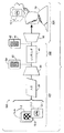
図3は、複合画像を形成するために複数のソース画像をスペクトル多重化する第1のモードか、複合画像をレンダリングする第2のモードか、又は、観察者により有利に見られるように複数のソース画像のうちの少なくとも1つを回復するためにスペクトル多重化された複合画像を逆多重化する第3のモードで作動可能なシステム100を示す。
図3に示すように、複数の異なるソース画像アレー11−1,11−2,...11−Nがスペクトル多重化システム101の画像入力装置20に表されている。画像入力装置20は、複数の単色画像、又は、単色及び多色画像の組合せを受信するように装備することができる。画像入力装置20は、ランダムアクセスメモリに結合されたデジタルスキャナのような画像捕捉装置か、又は、コンピュータメモリ又は磁気又は光学式記録媒体のような記憶手段に結合された任意の種類のアナログ又はデジタルカメラを含むことができる。画像入力装置20はまた、ランダムアクセスメモリ、ビデオテープ、又はレーザ符号化ディスクなどに先に記憶された画像を受信するか、又は、コンピュータ画像発生装置により作成された画像、又は適切なフォーマットで符号化されてネットワーク上で送信された画像を受信するための手段を含むことができる。
FIG. 3 illustrates a first mode in which a plurality of source images are spectrally multiplexed to form a composite image, a second mode in which the composite image is rendered, or a plurality of modes as advantageously seen by an observer. FIG. 4 illustrates a
As shown in FIG. 3, a plurality of different source image arrays 11-1, 11-2,. . . 11 -N is represented in the
この例において画像入力装置20により受信されたそれぞれの画像アレー内の複数のソース画像の例示的な図には、第1のソース画像アレー11−1で表された第1のソース画像12−1、及び、第2のソース画像アレー11−2で表された第2のソース画像12−2が含まれている。システム101は、任意選択的に、それぞれの画像アレーに表されたNソース画像を受信することができる。本発明のこの例示的な実施形態では、異なる絵によるソース画像が使用されており、複数のソース画像のうちの少なくとも1つは、複合画像からの最終的な回復(スペクトル逆多重化を通じて)を目的としたものである。
An exemplary view of a plurality of source images in each image array received by the
ソース画像データが画像入力装置20において受信されると、それは、スペクトルマルチプレクサ30に呈示され、スペクトルマルチプレクサ30は、複合画像32をスペクトル多重化(SM)画像平面上に供給するために、少なくとも第1及び第2のソース画像の複合画像のデータ表示を符号化する。このような符号化は、一実施形態では、各ソース画像に位置する対応する各ピクセルの符号化に必要な情報を多重化するために、複合画像32への各ピクセル位置に対するマッピングを行うか、又は、特定のピクセルではなく局所的領域でのマッピングにより進めることができる。
When source image data is received at the
次に、複合画像レンダリングシステム102の作動に従って、複合画像を表すデータは、電子情報を送信又は記憶する様々な適切な手段のいずれか1つによりスペクトルマルチプレクサ30に接続することができるレンダリング装置40に供給される。レンダリング装置40は、レンダリング複合画像42を形成するために、所定の狭帯域色素アレーを使用して基体44上に複合画像32を記録する。レンダリング複合画像42は、それによって基体44上に固定される。
Next, in accordance with the operation of the composite
レンダリング複合画像42は、観察者70が周囲光で見るのに利用可能である。レンダリング複合画像42は、本発明の方法を使用してスペクトル多重化平面に符号化されたデータを表すが、レンダリング複合画像42は、一般的に、従来の周囲照明条件では混乱した外観を呈し、すなわち、ソース画像12−1や12−2などの少なくとも1つは、従来の周囲照明条件の下では区別することが困難か又は不可能である。特定のソース画像は、所望のソース画像を示すのに十分な方法で複合画像42を選択的に照明するようにデマルチプレクサ50が作動するまで区別するのが困難か又は不可能な状態になっている。代替的に、ソース画像の1つ又はそれ以上は、視覚的な混乱を回避することにより、レンダリング複合画像が周囲又は広帯域照明を受けた時にはそれがレンダリング複合画像において視覚的に明らかであり、レンダリング複合画像が補完的狭帯域発光体を受けた時には混乱するか又は検出し難くなるように符号化することができる。
The rendered
スペクトル逆多重化システム103の作動に従って、特定のソース画像(図3に示すように、ソース画像12−1)を回復して複合画像42内で区別可能なもにすることができる。図3に示す実施形態では、デマルチプレクサ50の出力は、本発明の方法を用いて観察者70に向けられる。次に、回復された画像は、画像入力装置20に始めに供給された特定のソース画像12−1と実質的に同一か、又はその良好な近似として観察者70によって区別することができる。
In accordance with the operation of the
特定のソース画像の回復は、一般的に、以下の要領でスペクトル逆多重化システム103の例示的な実施形態に従って進行することが理解されるであろう。デマルチプレクサ50が発生させる狭帯域発光体が複合画像42を照明してレンダリング複合画像42内の色素のアレーが選択された発光体を受けるように、基体44は、デマルチプレクサ50内で作動可能な光源に対して配置される。レンダリング複合画像42がこのように少なくとも1つの発光体により制御可能かつ選択的に照明される結果として、次に、所望のソース画像が検出可能になる。図示した実施形態においては、所望のソース画像は、観察者70に対して視覚的に区別可能にされる。ここで回復された所望のソース画像12−1は、それにより観察者70が理解するようになる。
従って、色素とその対応する発光体の上述の相互作用により、及び、この特定の相互作用に対する観察者70の視覚的な応答により、符号化された各ソース画像は、逆多重化作動の目的により混乱した又は区別可能な画像として存在することができる。
It will be appreciated that the recovery of a particular source image generally proceeds according to an exemplary embodiment of the
Thus, due to the above-described interaction between the dye and its corresponding illuminant, and due to the viewer's 70 visual response to this particular interaction, each encoded source image will depend on the purpose of the demultiplexing operation. It can exist as a confused or distinguishable image.
図4は、それぞれ、スペクトル多重化、レンダリング、及びスペクトル逆多重化の方法61、62、及び63の例示的な実施形態の簡素化した概略図である。複数のソース画像を多重化する段階61において、第1のソース画像71及び第2のソース画像72がマルチプレクサ30に供給され、マルチプレクサ30は、複合画像データファイルをレンダリング装置40に出力する。レンダリング装置40の出力は、複合画像92を組み込んだ基体90である。元のソース画像71は、第1の色素を使用して、パターンとしてレンダリングされ、図示の実施形態では、シアンインク又はトナーが選択される。第2のソース画像72は、第2の色素を使用して、パターンとしてレンダリングされ、図示の実施形態においては、マゼンタインク又はトナーが選択される。(実際の狭帯域色素間では、一般的に吸収帯域内に何らかの重なりがあるので、複合画像を生成するために複数の色素が利用された時に発生することになる吸収に対処するために、2つのソース画像は、段階71で符号化されることが好ましい。)
FIG. 4 is a simplified schematic diagram of exemplary embodiments of spectral multiplexing, rendering, and
レンダリング段階62においては、複合画像は、基体90上で相応にレンダリングされるシアン色素及びマゼンタ色素のパターンを特定し、レンダリン複合画像92を形成する。当業者は、2つのパターンの特定の部分は同じ位置に配置することができ、他の部分は比較的に空間的に別々であることを理解するであろう。それでも尚、本発明のいくつかの実施形態においては、複合画像内のソース画像のうちの少なくとも1つの視覚的認識は、複合画像内に符号化されたソース画像間の混乱により困難か又は不可能にされる場合がある。
In the
レンダリングされた複合画像92を逆多重化する段階63において、レンダリング複合画像92が固定されている基体90は、デマルチプレクサ50により照明される。基体90の照明は、第1の照明モード51に従って制御されるので、第1のソース画像71は、複合画像の残りに対して特定レベルの密度を達成し、従って、第1のソース画像71は、基体90上で検出可能になる。代替的に、基体90の照明が第2の照明モード52に従って制御されると、第2のソース画像72が、同様に基体90上で検出可能にされる。従って、図示の実施形態においては、第1のソース画像71及び第2のソース画像72は、基体90上で選択的に区別することができる。
In
図5は、画像処理ユニット130、及び、関連周辺装置及びサブシステムが使用されている、図3のスペクトル多重化システム101の簡素化した概略図である。画像入力端末120は、スキャナ、デジタルカメラ、又は画像センサアレーのような画像捕捉装置122、コンピュータ画像発生装置124又は二次元データを画像に変換する類似の装置、又は、半導体メモリ又は磁気、光学、又は磁気光学データ記憶装置のような画像記憶装置126を含むことができる。画像入力端末120は、例えば、複数の単色画像ファイルの形でデジタル画像データを導出するか又は供給し、各画像の画像要素又は「ピクセル」は、あるグレー値で定義される。例えば、入力端末120は、一般的にmビット/ピクセルで形成されたピクセルを用いて、装置の物理的特性に関連したフォーマットで文書又は写真の電子的表現を画像捕捉装置122から得るために使用することができる。カラー文書の場合、画像は、2つ又はそれ以上の分離ビットマップを用いて、通常は同一の解像度及びピクセル深度で形成される。入力端末120からの画像データは、符号化して複合画像を作成するために、処理用の画像処理ユニット(IPU)130に向けられる。1つ又はそれ以上のソース画像を表すデータは、その後のレンダリングに適切な複合画像を表す二次画像データが得られるように、画像処理ユニット130によりスペクトル符号化されることが認識されるであろう。
FIG. 5 is a simplified schematic diagram of the
画像処理ユニット130は、入力画像データを画像入力端末120から、又は、適切にプログラムされた汎用コンピュータ(図示せず)のような別の適切な画像データ供給装置から受信し、ランダムアクセスメモリ(RAM)のような適切な装置に入力画像データを記憶する画像メモリ132を含むことができる。画像処理ユニット130は、一般にプロセッサ134を含む。入力画像データは、本発明に従ってそれぞれのソース画像平面上で形成された複数のソース画像を表す画像データをもたらすように、プロセッサ134を通じて処理することができる。例えば、「RGB」又は白黒(B/W)画像の形の画像データ信号を処理することができ、そこから得られた輝度情報を使用して、ソース画像を表すデータをもたらすことができる。他のフォーマットで示された画像データ信号も同様に処理され、例えば、L*a*bフォーマットの画像データ信号は、ソース画像を表すデータを明度チャンネルから取得するように処理することができる。グレースケールで既にフォーマット化されている画像データ信号は、一般的に、更に処理しなくても使用可能である。
The
画像処理ユニット130の作動は、ソース画像データを上述のような複合画像ファイルに符号化するために、1つ又はそれ以上の画像処理関数138及び139に従って進めることができる。処理には、必要であれば3成分カラー表示を特定プリンタ用の4つ又はそれ以上の成分のカラー表示に変換するために実行することができる色変換を含めることができ、また、c及びdを整数値であるとして、cビットデジタル画像信号を特定プリンタの駆動に適切なdビットデジタル画像信号に変換するハーフトナーを含めることができる。いくつかの実施形態においては、更に別の関数には、色空間変換、色補正、全領域マッピング、及びアンダー・カラー・リムーバル(UCR)/グレー成分置換(GCR)関数のうちの1つ又はそれ以上を含めることができる。制御信号及び複合画像出力データは、画像処理ユニット130からの出力のためにインタフェース136に供給される。
The operation of the
画像処理ユニット130は、内蔵プロセッサとして、又は、汎用コンピュータの一部として具体化することができる。それは、デジタル信号処理を達成するためなどの特殊目的のハードウェアを含むことができ、又は、単に汎用コンピュータ上で実行される適切なプログラムを表すことができる。それはまた、遠隔コンピュータ上で実行される1つ又はそれ以上の特殊目的プログラムを表す場合がある。
The
図6は、1つ又はそれ以上の回復されたソース画像171及び172を呈示するためにコントローラと関連周辺装置及びサブシステムとが使用されている、図3のスペクトル逆多重化システム103の簡素化された概略図である。図6は、基体44上の複合画像42を第1及び第2の所定の発光体161及び162に当てるように作動可能な光源160に接続されたコントローラ150を示す。第1に、基体44上のレンダリング複合画像42に関して図示するように、従来の周辺照明の下で、かつ発光体161及び162がない場合には、複合画像42のみが区別可能であり、ソース画像は検出されない。しかし、第1の所定の発光体161が得られるように光源160が作動されると、回復ソース画像171は、観察者170にとって検出可能になる。代替的に、光源160の作動モードは、第2の所定の照明162が得られるように切り替えることができ、その時点で、複合画像42は、代わりに第2の発光体162に当てられ、回復ソース画像172が検出可能になる。
FIG. 6 illustrates a simplification of the
コントローラ150は、その最も単純な形において、手動操作可能な発光体セレクタスイッチとして構成することができる。代替的に、図示するように、コントローラ150は、光源160の作動のプログラム可能な制御を提供する、光源160に接続されたインタフェース156を有するコンピュータベースの制御装置の形で設けることができる。すなわち、コントローラ150は、照明162の1つ又はそれ以上の選択された場をもたらすために、光源160の選択的作動及び停止を生じさせるように操作することができる。このような制御は、例えば、人間のオペレータによるか、又は、コンピュータ又は類似の手段によるプログラム可能な制御による光源160の手動操作を通じて達成することができる。
In its simplest form, the
コントローラ150は、光源160の作動、停止、又は順序付け、及び、発光体強度や発光体周波数の設定のようなタスクを達成するように作動可能である。コントローラ150の実施形態は、標準的なメモリ152及びプロセッサ154を備えたプログラム可能制御システムの作動からの恩典を受ける。コントローラ150は、例えば、均一な「R」又は「G」又は「B」画面画像をインタフェース156に供給し、光源160がCRTモニタの形で構成された場合に、その後に光源160上で表示するために使用することができる。
The
コントローラ150による光源160の作動は、特定の順序付けられた制御関数に従って進めることができ、それによって、例えば、光源160の制御された作動を提供し、選択された狭帯域発光体、又は選択された狭帯域発光体の強度の制御された作動の連続的な作動及び停止のような選択的な特性に従って、又は、発光体の特定のシーケンス、強度、又は持続時間のオペレータによる介入に従った対話型制御によって変動する照明の場が提供される。上述の通り、レンダリング複合画像は、そこに符号化された複数のソース画像を有するように、例えば、それぞれの第1及び第2の色素の少なくとも第1及び第2のパターンを有するように構成することができる。レンダリング複合画像には、それぞれの第1及び第2の狭帯域発光体による照明の時間的シーケンスを受けさせることができ、その結果、第1及び第2の回復ソース画像171及び172のそれぞれが連続的に区別可能であることを可能にする。
上述のように、光源160は、レンダリング複合画像42を照明するための十分な所要の照明の場を発生させるために、基体44に対して位置決め可能な画面を有するCRTモニタの形で設けることができる。
The operation of the
As described above, the
図7は、シアン色素及びマゼンタ色素を使用してレンダリングされた、第1及び第2ソース画像が符号化されたレンダリング複合画像であり、第1及び第2ソース画像は、CRTの赤色及び緑色発光体の下で回復可能である。
回復ソース画像が照明場において補完的発光体の連続を受けた時にそれぞれ異なる明度で回復されることになる2つ又はそれ以上のソース画像を符号化することにより、単純な動画効果を達成することができる。例えば、赤色照明の下では、複合画像の黄色の色素でレンダリングされた部分は、複合画像のシアン色素でレンダリングされた部分よりも明るく見える傾向がある。赤色発光体の代わりに青色発光体を使用した時には、それぞれの部分の見掛けの明度は逆になる。更に、ソース画像は、黄色及びシアン色素を使用してレンダリングされた複合画像内に符号化及び構成されたソース画像の外観に、それぞれが赤色及び青色発光体を受ける時に適合することになるグレー又は緑色色素を使用してレンダリングされた複合画像内に符号化及び構成することができる。
FIG. 7 is a rendered composite image rendered using cyan and magenta dyes, encoded with first and second source images, wherein the first and second source images are CRT red and green emission. Recoverable under the body.
Achieving a simple animation effect by encoding two or more source images, each of which will be recovered with different brightness when the recovered source image undergoes a sequence of complementary illuminants in the illumination field Can do. For example, under red illumination, the portion of the composite image rendered with the yellow dye tends to appear brighter than the portion of the composite image rendered with the cyan dye. When a blue light emitter is used instead of a red light emitter, the apparent brightness of each part is reversed. In addition, the source image is either gray or gray which will match the appearance of the source image encoded and constructed in the composite image rendered using yellow and cyan dyes, respectively, when receiving red and blue emitters. It can be encoded and organized in a composite image rendered using a green pigment.
図8は、第1、第2、及び第3の複数の空間変動ソース画像が符号化されたレンダリング複合画像の概略図である。
図9は、レンダリング複合画像が狭帯域発光体の照明の場のシーケンスを受ける時に、回復ソース画像間又は回復ソース画像内に運動の感覚を付与するために回復される複数の第1、第2、及び第3の空間変動ソース画像が符号化された、図8の概略図に従って構成されたレンダリング複合画像を示す図である。
FIG. 8 is a schematic diagram of a rendered composite image in which a first, second, and third plurality of spatially varying source images are encoded.
FIG. 9 shows a plurality of first and second images that are recovered to impart a sensation of motion between or within the recovery source images when the rendered composite image undergoes a sequence of illumination fields of a narrowband illuminant. FIG. 9 shows a rendered composite image constructed according to the schematic diagram of FIG. 8, encoded with a third spatial variation source image.
11−1 第1のソース画像アレー
12−1 第1のソース画像
20 画像入力装置
30 スペクトルマルチプレクサ
32 複合画像
40 レンダリング装置
42 レンダリング複合画像
44 基体
50 デマルチプレクサ
70 観察者
101 スペクトル多重化システム
102 複合画像レンダリングシステム
103 スペクトル逆多重化システム
11-1 First source image array 12-1
Claims (2)
複数の色素を使用して該複合画像のデータを基体上に画像の表示をする段階であって、複数のソース画像が、前記複合画像から、前記複数のソース画像の少なくとも一つが、観察者に区別することができないか若しくは困難であるように複合画像に混合される画像の表示をする段階と、
各々が関連するソース画像を示すように予め選択された複数の狭帯域発光体に表示をされた前記複合画像を当てることにより、復元したソース画像の各々が区別可能になるように前記符号化されたソース画像を表示された前記複合画像からスペクトル逆多重化するように復元させる段階と、
を含み、
前記組み合わされた値は、(a)色素/発光体相互作用に対する人間の視覚的応答の三色色度、(b)前記複合画像を表示するために選択された前記色素のスペクトル特性、及び(c)前記ソース画像を復元するために使用される前記狭帯域発光体のスペクトル特性のうちの少なくとも1つに従って判断され、
切り替えられた発光体のシーケンスは、対応するソース画像のシーケンスを連続して復元させる、
ことを特徴とする、複数のソース画像を処理する方法。 A value representing the pixels of each source image, using a look-up table for deriving a plurality of dye value from the plurality of luminance values, and corrects the unnecessary absorption by the dye of the other source image, a plurality of dye pixel plane by combining the corresponding pixel values in one or more out, the data of each of the plurality of source image data of the composite image, the method comprising spectral multiplexing,
Displaying the composite image data on a substrate using a plurality of dyes, the plurality of source images from the composite image, and at least one of the plurality of source images to the observer; Displaying an image that is mixed into the composite image so that it cannot be distinguished or difficult ;
Each of the restored source images is encoded so that each of the restored source images is distinguishable by applying the displayed composite image to a plurality of pre-selected narrowband emitters, each showing an associated source image. Restoring the source image to be spectrally demultiplexed from the displayed composite image;
Including
The combined values are, (a) a dye / three-color chromaticity of the human visual response to light emitters interactions, (b) the spectral characteristics of the dye that is selected to display a composite image, and (c ) Determined according to at least one of the spectral characteristics of the narrowband illuminator used to reconstruct the source image;
The switched illuminant sequence continuously restores the corresponding source image sequence,
A method for processing a plurality of source images.
該複合画像データ信号を受信し、該複合画像を基体上に画像の表示をするための、前記スペクトルマルチプレクサに応答する画像表示装置であって、複数のソース画像が、前記複合画像から、前記複数のソース画像の少なくとも一つが、観察者に区別することができないか若しくは困難であるように複合画像に混合される画像表示装置と、
各々が関連するソース画像を示すように予め選択された複数の狭帯域発光体に表示された前記複合画像を当てることにより、復元したソース画像が区別可能になるように前記符号化されたソース画像を表示された該複合画像から復元させるためのデマルチプレクサと、
を含み、
前記組み合わされた値は、(a)色素/発光体相互作用に対する人間の視覚的応答の三色色度、(b)前記複合画像を表示するために選択された前記色素のスペクトル特性、及び(c)前記ソース画像を復元するために使用される前記狭帯域発光体のスペクトル特性のうちの少なくとも1つに従って判断され、
切り替えられた発光体のシーケンスは、対応するソース画像のシーケンスを連続して復元させる、
ことを特徴とする画像化システム。 A value representing each source image pixel is received and a lookup table that derives a plurality of dye values from a plurality of luminance values is used to correct unwanted absorption by the dyes of other source images, and the received values Are combined with corresponding pixel values in respective dye image planes, receiving image data representing multiple source images, and spectrally multiplexing each of the source image image data into composite image data A spectral multiplexer for processing the image data to prepare a composite image data signal,
Receiving the composite image data signal, for the display of the image the composite image on a substrate, an image display device responsive to the spectral multiplexer, a plurality of source images, from the composite image, the plurality at least one of the source image, and an image display device which is mixed in the composite image as it is difficult or either not be able to distinguish the observer,
The encoded source image so that the reconstructed source image is distinguishable by applying the composite image displayed on a plurality of preselected narrowband light emitters, each showing an associated source image A demultiplexer for restoring from the displayed composite image;
Including
The combined values are, (a) a dye / three-color chromaticity of the human visual response to light emitters interactions, (b) the spectral characteristics of the dye that is selected to display a composite image, and (c ) Determined according to at least one of the spectral characteristics of the narrowband illuminator used to reconstruct the source image;
The switched illuminant sequence continuously restores the corresponding source image sequence,
An imaging system characterized by that.
Applications Claiming Priority (2)
| Application Number | Priority Date | Filing Date | Title |
|---|---|---|---|
| US10/268,394 US7136522B2 (en) | 2002-10-09 | 2002-10-09 | Systems for spectral multiplexing of source images to provide a composite image, for rendering the composite image, and for spectral demultiplexing of the composite image to animate recovered source images |
| US10/268394 | 2002-10-09 |
Publications (3)
| Publication Number | Publication Date |
|---|---|
| JP2004133932A JP2004133932A (en) | 2004-04-30 |
| JP2004133932A5 JP2004133932A5 (en) | 2006-11-16 |
| JP4920866B2 true JP4920866B2 (en) | 2012-04-18 |
Family
ID=32030365
Family Applications (1)
| Application Number | Title | Priority Date | Filing Date |
|---|---|---|---|
| JP2003344714A Expired - Fee Related JP4920866B2 (en) | 2002-10-09 | 2003-10-02 | System for spectral multiplexing and rendering of source images and spectral demultiplexing to form animated source images |
Country Status (3)
| Country | Link |
|---|---|
| US (1) | US7136522B2 (en) |
| EP (1) | EP1407899A1 (en) |
| JP (1) | JP4920866B2 (en) |
Families Citing this family (18)
| Publication number | Priority date | Publication date | Assignee | Title |
|---|---|---|---|---|
| US6807759B1 (en) * | 2002-12-30 | 2004-10-26 | David G. Burder | Method for viewing a full color animation |
| FR2859857A1 (en) * | 2003-09-17 | 2005-03-18 | Thomson Licensing Sa | Source image processing method for e.g. projector, involves compensating modified colors of pixels on processed images to obtain color corresponding to color of pixel in source image, where luminance of pixels in images are equal |
| US7269297B2 (en) * | 2003-11-25 | 2007-09-11 | Xerox Corporation | Illuminant-neutral gray component replacement in systems for spectral multiplexing of source images to provide a composite image, for rendering the composite image, and for spectral demultiplexing of the composite image |
| US7379588B2 (en) * | 2003-11-25 | 2008-05-27 | Xerox Corporation | Systems for spectral multiplexing of source images to provide a composite image, for rendering the composite image, and for spectral demultiplexing the composite image to obtain a normalized color image |
| US7758422B2 (en) * | 2005-04-13 | 2010-07-20 | Microsoft Corporation | Hard drive authentication |
| EP1943605A1 (en) * | 2005-11-04 | 2008-07-16 | Christian Hogl | Method and system for transmitting data from a first data processing device to a second data processing device |
| US7525704B2 (en) * | 2005-12-20 | 2009-04-28 | Xerox Corporation | System for providing depth discrimination of source images encoded in a rendered composite image |
| US8218822B2 (en) * | 2007-05-14 | 2012-07-10 | Pips Technology, Inc. | Apparatus and method for recognizing the state of origin of a vehicle license plate |
| US7852515B2 (en) * | 2007-06-05 | 2010-12-14 | Xerox Corporation | Infrared encoding for embedding multiple variable data information collocated in printed documents |
| US20090267891A1 (en) * | 2008-04-25 | 2009-10-29 | Bamidele Ali | Virtual paper |
| US8520934B2 (en) * | 2008-06-13 | 2013-08-27 | Thomson Licensing | System and method for marking a stereoscopic film |
| US8345958B2 (en) * | 2009-12-31 | 2013-01-01 | Industrial Technology Research Institute | Method and system for developing new-view image |
| RU2535430C1 (en) * | 2010-11-15 | 2014-12-10 | Нэшнл Инститьют Оф Джапэн Сайнс Энд Текнолоджи Эйдженси | Illusion image generating apparatus, medium, image data, illusion image generating method, printing medium manufacturing method and programme |
| US8385640B2 (en) | 2011-07-13 | 2013-02-26 | Eastman Kodak Company | System for controlling dynamic optical illusion images |
| US8616460B2 (en) | 2011-07-13 | 2013-12-31 | Eastman Kodak Company | Method for providing dynamic optical illusion images |
| US8616461B2 (en) | 2011-07-13 | 2013-12-31 | Eastman Kodak Company | Printed dynamic optical illusion images |
| WO2019133915A1 (en) | 2017-12-29 | 2019-07-04 | Guntert & Zimmerman Const. Div., Inc. | Extended width dowel bar inserter |
| CN114863291B (en) * | 2022-04-20 | 2023-08-08 | 重庆市地理信息和遥感应用中心 | Hyperspectral image band selection method based on MCL and spectrum difference measurement |
Family Cites Families (32)
| Publication number | Priority date | Publication date | Assignee | Title |
|---|---|---|---|---|
| GB168880A (en) * | 1920-08-30 | 1922-03-23 | Nadine De Boudkowsky | Process for obtaining, on the same support, different pictures rendered alternately visible by a modification of the lighting |
| US1681776A (en) * | 1925-02-18 | 1928-08-21 | James P Mcdonnell | Apparatus for producing optical effects from pictures |
| GB438113A (en) * | 1934-04-03 | 1935-11-04 | John Gordon Best | Improvements in illuminated signs |
| CH350909A (en) * | 1956-10-22 | 1960-12-15 | Michel Eugen | Optical toys |
| US3234663A (en) | 1963-04-01 | 1966-02-15 | Bausch & Lomb | Film coding method |
| JPS4939001B1 (en) * | 1971-04-14 | 1974-10-22 | ||
| JPS5343121Y2 (en) * | 1972-02-24 | 1978-10-17 | ||
| US3908193A (en) * | 1972-11-27 | 1975-09-23 | Albert Macovski | Color television encoding and decoding system |
| US3969830A (en) | 1972-12-01 | 1976-07-20 | Grasham James A | Color encoding-decoding method |
| US4290675A (en) | 1978-12-04 | 1981-09-22 | Leo Beiser | Anaglyph stereoscopy |
| JPS59149178U (en) * | 1983-03-24 | 1984-10-05 | 株式会社東海理化電機製作所 | display device |
| US4586711A (en) | 1983-05-10 | 1986-05-06 | Glenn E. Weeks | Matching card game employing randomly-coded monochromatic images |
| GB8417297D0 (en) * | 1984-07-06 | 1984-08-08 | Shell Int Research | Preparation of sulphurized overbased salicylates |
| US4824144A (en) | 1987-04-10 | 1989-04-25 | Tasma Gerald W | Color identification system |
| GB2223619A (en) * | 1988-09-11 | 1990-04-11 | Saieb Muslih Khalil | Light projecting arrangements for advertisements etc |
| WO1990012336A1 (en) * | 1989-03-30 | 1990-10-18 | Cyril Redford | Optical illusion system |
| GB9019784D0 (en) * | 1990-09-10 | 1990-10-24 | Amblehurst Ltd | Security device |
| ATE168210T1 (en) | 1991-11-05 | 1998-07-15 | Printpack Inc | OPTICAL METHOD FOR ENCODERING AND DECRYPTING IMAGES |
| GB2261789B (en) | 1991-11-20 | 1995-07-19 | Stephen Peter Ehrmann Erskine | Improvements in or relating to the production of anaglyphs |
| JP2560228B2 (en) * | 1992-03-18 | 1996-12-04 | 大蔵省印刷局長 | Multi-source image display and multi-source image display method |
| US5398131A (en) | 1992-08-13 | 1995-03-14 | Hall; Dennis R. | Stereoscopic hardcopy methods |
| US5699184A (en) * | 1992-08-13 | 1997-12-16 | Hall; Dennis R. | Use of stereoscopic display systems utilizing chiral liquid crystals |
| US5371627A (en) | 1992-10-23 | 1994-12-06 | N.E. Thing Enterprises, Inc. | Random dot stereogram and method for making the same |
| JPH0734390A (en) * | 1993-07-13 | 1995-02-03 | Sumitomo Chem Co Ltd | Colored product having figure pattern |
| US6111598A (en) | 1993-11-12 | 2000-08-29 | Peveo, Inc. | System and method for producing and displaying spectrally-multiplexed images of three-dimensional imagery for use in flicker-free stereoscopic viewing thereof |
| US5594841A (en) | 1993-12-27 | 1997-01-14 | Schutz; Stephen A. | Stereogram and method of constructing the same |
| US6404464B1 (en) * | 1995-10-30 | 2002-06-11 | Reveo, Inc. | Method and system for producing color images with improved brightness and color characteristics on radiation absorptive surfaces |
| JP3567184B2 (en) * | 1998-04-15 | 2004-09-22 | 独立行政法人 国立印刷局 | Color latent image display method and color latent image display |
| US6301044B1 (en) | 2000-03-30 | 2001-10-09 | Disney Enterprises, Inc. | Apparel color and image effect system |
| JP4974314B2 (en) * | 2001-04-19 | 2012-07-11 | 大日本塗料株式会社 | Hidden display identification method |
| US7376264B2 (en) * | 2002-10-09 | 2008-05-20 | Xerox Corporation | Systems for spectral multiplexing of a source image and a background image to provide a composite image, for rendering the composite image, and for spectral demultiplexing of the composite images |
| US7218785B2 (en) * | 2002-10-09 | 2007-05-15 | Xerox Corporation | Systems for spectral multiplexing of source images to provide a composite image, for rendering the composite image, and for spectral demultiplexing of the composite image |
-
2002
- 2002-10-09 US US10/268,394 patent/US7136522B2/en not_active Expired - Fee Related
-
2003
- 2003-10-02 JP JP2003344714A patent/JP4920866B2/en not_active Expired - Fee Related
- 2003-10-09 EP EP20030022949 patent/EP1407899A1/en not_active Ceased
Also Published As
| Publication number | Publication date |
|---|---|
| JP2004133932A (en) | 2004-04-30 |
| US20040071348A1 (en) | 2004-04-15 |
| EP1407899A1 (en) | 2004-04-14 |
| US7136522B2 (en) | 2006-11-14 |
Similar Documents
| Publication | Publication Date | Title |
|---|---|---|
| JP4252418B2 (en) | Method and system for processing multiple source images | |
| JP4920866B2 (en) | System for spectral multiplexing and rendering of source images and spectral demultiplexing to form animated source images | |
| JP2004166251A (en) | System for spectrally multiplexing source image to provide composite image, rendering composite image, and spectrally demultiplexing composite image | |
| US5748858A (en) | Method of and system for predicting reproduced color image | |
| US6459436B1 (en) | Image processing method and apparatus | |
| JP5021158B2 (en) | Source-neutral gray component replacement in a system for spectrally multiplexing a source image to represent the composite image, representing the composite image, and demultiplexing such composite image | |
| JP5214840B2 (en) | A system for spectral multiplexing of a source image for displaying a composite image and for providing a composite image for spectral demultiplexing of the composite image to obtain a normalized color image | |
| JPH07212607A (en) | Color image formation system and method | |
| US7230738B2 (en) | System for spectral multiplexing of source image to provide a composite image with noise encoding to increase image confusion in the composite image, for rendering the composite image, and for spectral demultiplexing of the composite image | |
| US6989839B2 (en) | Method for converting color to monochrome to maintain differentiability | |
| US7130488B2 (en) | Systems for spectral multiplexing of source images including a textured source image to provide a composite image, for rendering the composite image, and for spectral demultiplexing of the composite image | |
| CN108810315A (en) | Information processing unit, image processing system, control system and information processing method | |
| JPH114353A (en) | Image processing method and system | |
| JP2007174126A (en) | Image processing apparatus and method | |
| JP4533291B2 (en) | Color processing method and apparatus | |
| JP3535778B2 (en) | Image processing method, apparatus and recording medium | |
| JP3667171B2 (en) | Image processing method, apparatus, and recording medium | |
| JP2002077652A (en) | Image processing method and recording medium | |
| Dilawari et al. | Reproduction of images by gamut mapping and creation of new test charts in prepress process | |
| Zhang et al. | i, United States Patent (10) Patent No.: US 7.269. 297 B2 | |
| JP2005210551A (en) | Image processing algorithm |
Legal Events
| Date | Code | Title | Description |
|---|---|---|---|
| A521 | Request for written amendment filed |
Free format text: JAPANESE INTERMEDIATE CODE: A523 Effective date: 20060929 |
|
| A621 | Written request for application examination |
Free format text: JAPANESE INTERMEDIATE CODE: A621 Effective date: 20060929 |
|
| A131 | Notification of reasons for refusal |
Free format text: JAPANESE INTERMEDIATE CODE: A131 Effective date: 20081222 |
|
| A521 | Request for written amendment filed |
Free format text: JAPANESE INTERMEDIATE CODE: A523 Effective date: 20090323 |
|
| A131 | Notification of reasons for refusal |
Free format text: JAPANESE INTERMEDIATE CODE: A131 Effective date: 20090629 |
|
| A601 | Written request for extension of time |
Free format text: JAPANESE INTERMEDIATE CODE: A601 Effective date: 20090929 |
|
| A602 | Written permission of extension of time |
Free format text: JAPANESE INTERMEDIATE CODE: A602 Effective date: 20091002 |
|
| A601 | Written request for extension of time |
Free format text: JAPANESE INTERMEDIATE CODE: A601 Effective date: 20091029 |
|
| A602 | Written permission of extension of time |
Free format text: JAPANESE INTERMEDIATE CODE: A602 Effective date: 20091104 |
|
| A601 | Written request for extension of time |
Free format text: JAPANESE INTERMEDIATE CODE: A601 Effective date: 20091130 |
|
| A602 | Written permission of extension of time |
Free format text: JAPANESE INTERMEDIATE CODE: A602 Effective date: 20091203 |
|
| A521 | Request for written amendment filed |
Free format text: JAPANESE INTERMEDIATE CODE: A523 Effective date: 20091225 |
|
| A131 | Notification of reasons for refusal |
Free format text: JAPANESE INTERMEDIATE CODE: A131 Effective date: 20100208 |
|
| A601 | Written request for extension of time |
Free format text: JAPANESE INTERMEDIATE CODE: A601 Effective date: 20100430 |
|
| A602 | Written permission of extension of time |
Free format text: JAPANESE INTERMEDIATE CODE: A602 Effective date: 20100510 |
|
| A601 | Written request for extension of time |
Free format text: JAPANESE INTERMEDIATE CODE: A601 Effective date: 20100608 |
|
| A602 | Written permission of extension of time |
Free format text: JAPANESE INTERMEDIATE CODE: A602 Effective date: 20100611 |
|
| A521 | Request for written amendment filed |
Free format text: JAPANESE INTERMEDIATE CODE: A523 Effective date: 20100707 |
|
| A02 | Decision of refusal |
Free format text: JAPANESE INTERMEDIATE CODE: A02 Effective date: 20100726 |
|
| A521 | Request for written amendment filed |
Free format text: JAPANESE INTERMEDIATE CODE: A523 Effective date: 20101126 |
|
| A911 | Transfer to examiner for re-examination before appeal (zenchi) |
Free format text: JAPANESE INTERMEDIATE CODE: A911 Effective date: 20101206 |
|
| A912 | Re-examination (zenchi) completed and case transferred to appeal board |
Free format text: JAPANESE INTERMEDIATE CODE: A912 Effective date: 20101224 |
|
| A01 | Written decision to grant a patent or to grant a registration (utility model) |
Free format text: JAPANESE INTERMEDIATE CODE: A01 |
|
| A61 | First payment of annual fees (during grant procedure) |
Free format text: JAPANESE INTERMEDIATE CODE: A61 Effective date: 20120202 |
|
| R150 | Certificate of patent or registration of utility model |
Free format text: JAPANESE INTERMEDIATE CODE: R150 |
|
| FPAY | Renewal fee payment (event date is renewal date of database) |
Free format text: PAYMENT UNTIL: 20150210 Year of fee payment: 3 |
|
| R250 | Receipt of annual fees |
Free format text: JAPANESE INTERMEDIATE CODE: R250 |
|
| R250 | Receipt of annual fees |
Free format text: JAPANESE INTERMEDIATE CODE: R250 |
|
| R250 | Receipt of annual fees |
Free format text: JAPANESE INTERMEDIATE CODE: R250 |
|
| LAPS | Cancellation because of no payment of annual fees |