JP4919619B2 - Butterfly water level control valve - Google Patents
Butterfly water level control valve Download PDFInfo
- Publication number
- JP4919619B2 JP4919619B2 JP2005157171A JP2005157171A JP4919619B2 JP 4919619 B2 JP4919619 B2 JP 4919619B2 JP 2005157171 A JP2005157171 A JP 2005157171A JP 2005157171 A JP2005157171 A JP 2005157171A JP 4919619 B2 JP4919619 B2 JP 4919619B2
- Authority
- JP
- Japan
- Prior art keywords
- water level
- butterfly
- valve
- gear mechanism
- lever
- Prior art date
- Legal status (The legal status is an assumption and is not a legal conclusion. Google has not performed a legal analysis and makes no representation as to the accuracy of the status listed.)
- Expired - Fee Related
Links
Images


Landscapes
- Float Valves (AREA)
- Lift Valve (AREA)
Description
本発明は蝶形水位調整弁、特にあらゆる用途の配水池、貯水池、貯水槽、減圧水槽等にあってフロートの昇降に追動してギアを稼動させ蝶弁による流路の開閉を行なう蝶形水位調整弁に関する。 The present invention relates to a butterfly-shaped water level adjustment valve, particularly a butterfly-shaped valve that opens and closes a flow path by a butterfly valve by operating a gear by following up and down of a float in a reservoir, a reservoir, a water tank, a depressurized water tank, etc. It relates to a water level adjustment valve.
従来、上記したギア駆動によって蝶弁を作動させる水位調整弁はそのギアとして扇形ギアを用いている。一般的にギア駆動で蝶弁を動作させるについて、屋外配備とされる場合、そのギア機構に水面に浮遊あるいは飛来するわら屑、落葉、木片等の異物が噛み込むとそのギア機構の動作不良の原因となってしまう。 Conventionally, a water level adjusting valve that operates a butterfly valve by driving the gear as described above uses a sector gear as its gear. In general, when operating a butterfly valve by gear drive, if it is deployed outdoors, if the gear mechanism is trapped by foreign matter such as straw debris, fallen leaves, or wood chips floating or flying on the surface of the water, the gear mechanism will malfunction. It becomes a cause.
そこで、出願人が提示する特許文献に示されるように扇形ギアの噛合部分を覆う構成のものがあるが、先端に扇形ギアを形成したレバーの回動を許容するため、その覆いにはどうしても部分的に開放される透孔が必要とされ、その透孔の開放部分から前記した異物がギア機構に侵入してしまうことを完全に防止することはできないものとなっていた。
本発明が解決しようとする問題点は、従来のギア機構を用いた蝶形水位調整弁はどうしてもギア機構のカバー(ケース)に開放された透孔が存在してしまい、完全に異物の侵入を防止することはできず、作動不良を生じる原因となっていたという点である。 The problem to be solved by the present invention is that a butterfly-shaped water level adjustment valve using a conventional gear mechanism inevitably has an open hole in the cover (case) of the gear mechanism, so that foreign matter can be completely prevented from entering. It cannot be prevented, and is a cause of malfunction.
上記した問題点を解決するために、本発明に係る蝶形水位調整弁は下方に水位の変動に追動するフロートを備えた支持ロッドを有し、その支持ロッドの上端寄りにレバー桿を枢着し、そのレバー桿の先端に弁箱内に軸支された蝶弁体を駆動させるギア機構を連結し、前記ギア機構の全外周をカバー体で気密に覆ってあり、前記した支持ロッドには遊び間隔をもってフロートのストッパーを備えている蝶形水位調整弁において、前記したギア機構はレバー桿の先端に連結されたピニオンとそのピニオンが内接する内歯ギアとし、その内歯ギアに同期して回動する連結プレートを介して蝶弁体の弁軸を連結させてあることを特徴としている。 In order to solve the above-mentioned problems, the butterfly-shaped water level regulating valve according to the present invention has a support rod provided with a float that follows the fluctuation of the water level below, and a lever rod is pivoted near the upper end of the support rod. A gear mechanism for driving a butterfly valve body pivotally supported in the valve box is connected to the tip of the lever rod, and the entire outer periphery of the gear mechanism is covered with a cover body in an airtight manner. Is a butterfly level control valve equipped with a float stopper with a play interval, and the gear mechanism described above is a pinion connected to the tip of the lever と and an internal gear in which the pinion is inscribed, and is synchronized with the internal gear. The valve shaft of the butterfly valve body is connected through a connecting plate that rotates in this manner.
また、本発明に係る蝶形水位調整弁は前記したギア機構のカバー体の外面に、前記したレバー桿のストッパーを少なくとも一以上設けてあることを特徴としている。 In addition, the butterfly-shaped water level adjusting valve according to the present invention is characterized in that at least one stopper of the lever rod is provided on the outer surface of the cover body of the gear mechanism.
本発明に係る蝶形水位調整弁は上記のように構成されている。そのため、請求項1に記載の発明によれば、ギア機構が完全に覆われ、異物の侵入する虞は一切なくなることとなり、完全なギア機構の気密カバーリング構造を具体的に実現することができることとなる。 The butterfly water level adjusting valve according to the present invention is configured as described above. Therefore, according to the first aspect of the present invention, the gear mechanism is completely covered, and there is no possibility of foreign matter intruding, so that an airtight covering structure of the complete gear mechanism can be specifically realized. It will be possible.
また、請求項2に記載の発明によれば、想定されている最高、最低の水位位置にフロートがある時、それを越えて蝶弁を動作させてしまうことが防止される。
Further, according to the second aspect of the present invention, when there is a float at the assumed maximum and minimum water level positions, it is possible to prevent the butterfly valve from operating beyond that .
図面として示す実施例のように構成することで実現した。 This is realized by configuring as in the embodiment shown in the drawings.
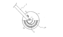
次に、本発明の好ましい実施の一例を図面を参照して説明する。図1は本発明を実施した蝶形水位調整弁を示す正面図、図2は同じくギア機構部分を示す一部破断正面図、図3は同じくギア機構部分を示す側断面図である。 Next, an example of a preferred embodiment of the present invention will be described with reference to the drawings. FIG. 1 is a front view showing a butterfly water level adjusting valve embodying the present invention, FIG. 2 is a partially cutaway front view showing the gear mechanism portion, and FIG. 3 is a side sectional view showing the gear mechanism portion.
これらの図にあって1はフロートを示しており、図1は水位が最高位にある状態を示している。フロート1は支持ロッド6の下方に、その支持ロッド6を貫通させた状態で装着され、その支持ロッド6に沿って摺動自在のものとされている。 In these drawings, 1 indicates a float, and FIG. 1 indicates a state where the water level is at the highest level. The float 1 is mounted below the support rod 6 with the support rod 6 penetrating therethrough, and is slidable along the support rod 6.
また、前記した支持ロッド6にはフロート1の上下にストッパリング7a、7bがそのストッパリング7a、7bの外周から貫通される止めネジ8、8‥を支持ロッド6の外面に当圧接させることで備えられており、特に下方のストッパリング7bはフロート1の下面と遊び間隔を隔てて備えられているもので、特にフロート1が最高水位位置にある時、波の影響で下降してもその遊び間隔で吸収し、後述する蝶弁4の微動作を生じさせることがないようにしている。 In addition, stopper rings 7a and 7b above and below the float 1 are brought into pressure contact with the outer surface of the support rod 6 by means of stopper screws 7a and 7b penetrating from the outer periphery of the stopper rings 7a and 7b. In particular, the lower stopper ring 7b is spaced apart from the lower surface of the float 1 by a play interval. Especially when the float 1 is at the highest water level, the play is not affected even if it is lowered by the influence of waves. Absorption is performed at intervals, so that a minute operation of the butterfly valve 4 described later is not caused.
さらに、前記した支持ロッド6の上端寄りにはレバー桿2の一端寄り部分が枢支ピン9によって枢着されている。この枢支ピン2の先端にはリングナット10が一体的に設けられている。
Furthermore, a portion near one end of the
一方、図中11は後述するギア機構のカバー体を示しており、このカバー体11は略円筒状に形成され、その一方の開口に形成されている環状フランジ11aに略同径として円板状の蓋板12がボルト13により気密に固着されている。
On the other hand, reference numeral 11 denotes a cover body of a gear mechanism, which will be described later. The cover body 11 is formed in a substantially cylindrical shape, and has a disk shape with an approximately the same diameter as an annular flange 11a formed in one opening. The
また、前記した蓋板12にはその中心よりやや偏心位置に透孔が穿設され、その透孔にはブッシュ14が嵌装されている。このブッシュ14の外方への突出端面には前記したリングナット10が重合状態で合わせられ、そのリングナット10にはブッシュ14を貫通するボルト部材15が螺着され、抜け止め部材を介し固装されている。
Further, the
前記したボルト部材15の先端部分には小径のピニオン3が螺合固定されて備えられており、そのピニオン3はカバー体11と同心円状に配置された内歯ギア3aと噛合されている。この内歯ギア3aはその背面側で、内歯ギア3aの外径と略同一のサイズを有する連結プレート16がブッシュ17、17を介してネジ17aによって固着されている。
A small-
さらに、前記した連結プレート16の中心部位は支持用の六角筒体18に嵌着されており、この六角筒体18は弁箱19内から延設されている弁軸20に嵌め付けられ、ネジ21及びワッシャー22によって抜け止めが図られている。
Further, the central portion of the connecting plate 16 is fitted into a supporting hexagonal cylinder 18, and this hexagonal cylinder 18 is fitted into a
なお、本実施例にあって六角筒体18を用いてあるがこれは内歯ギア3aの回転力を連結プレート16を介して弁軸20に伝達するためのものであり、係合性があればよく、他の角筒体や楕円筒等で代替することも勿論可能である。
In the present embodiment, the hexagonal cylinder 18 is used, but this is for transmitting the rotational force of the internal gear 3a to the
前記した弁軸20は弁箱19に一体成形されたガイドパイプ23内に挿通され、弁箱19内で、その基端部分に蝶形弁体4が取り付けられている。また、ガイドパイプ23の開口縁のフランジ23aはカバー体11に形成された透孔11bの開口縁と気密に当圧接され、その透孔11bにフランジ23aの内縁に形成された嵌合段部23bが嵌着されている。そして、その嵌合段部23bには弁軸20の周囲を囲み、気密性を保持するガードリング24がネジにより固着されている。
The above-described
また、図中25、25は蓋板12の表面に固設されたレバー桿2の制御ストッパーであり、一定の水位位置までフロート1が昇降すると、それを越えてのレバー桿2の枢動を抑え、一定水位における蝶形弁体4の作動を抑えることができるものとしている。
In the figure, 25 and 25 are control stoppers of the
本発明に係る蝶形水位調整弁は上記したように構成されている。ここでこの動作を説明すると、水位の変位に伴なってフロート1が昇降すると、支持ロッド6も同期して昇降し、その支持ロッド6に枢着されているレバー桿2を枢動させる。その際、レバー桿2の枢動はボルト部材15を介してピニオン3に伝わり、このピニオン3は噛合されている内歯ギア3aを回転させる。この回転力が連結プレート16、六角筒体18を介して弁軸20に伝達され蝶形弁体4を開閉作動させることとなる。
The butterfly water level regulating valve according to the present invention is configured as described above. Here, this operation will be described. When the float 1 moves up and down with the displacement of the water level, the support rod 6 also moves up and down in synchronization, and the
そして、前記したギア機構は気密にカバー体11、蓋板12によって覆われているので、異物がギア機構に侵入し、噛み込んで作動不良を生じることは一切ない構造となっている。
And since the above-mentioned gear mechanism is airtightly covered with the cover body 11 and the
本発明は上述した構造とされているため、蝶形水位調整弁にこだわらず、スイングあるいは回転、回動する対象物をギア駆動する装置にも広く応用が可能となり、フロートをウエイトに代えること等でも、物品の排出ドアや換気窓の開閉等に利用することが可能となり、ギア機構に異物が侵入することを完全に防止することができることとなる。 Since the present invention has the above-described structure, the present invention can be widely applied to a device that drives a swinging, rotating, or rotating object without being particular about the butterfly water level adjusting valve, and the float is replaced with a weight. However, it can be used to open and close an article discharge door and a ventilation window, and it is possible to completely prevent foreign matter from entering the gear mechanism.
1 フロート
2 レバー桿
3 ピニオン
3a 内歯ギア
4 蝶形弁体
6 支持ロッド
7a ストッパリング
7b ストッパリング
8 止めネジ
9 枢支ピン
10 リングナット
11 カバー体
11a フランジ
11b 透孔
12 蓋板
13 ボルト
14 ブッシュ
15 ボルト部材
16 連結プレート
17 ブッシュ
17a ネジ
18 六角筒体
19 弁箱
20 弁軸
21 ネジ
22 ワッシャー
23 ガイドパイプ
23a フランジ
24 ガードリング
25 制御ストッパー
DESCRIPTION OF SYMBOLS 1
Claims (2)
Priority Applications (1)
| Application Number | Priority Date | Filing Date | Title |
|---|---|---|---|
| JP2005157171A JP4919619B2 (en) | 2005-05-30 | 2005-05-30 | Butterfly water level control valve |
Applications Claiming Priority (1)
| Application Number | Priority Date | Filing Date | Title |
|---|---|---|---|
| JP2005157171A JP4919619B2 (en) | 2005-05-30 | 2005-05-30 | Butterfly water level control valve |
Publications (2)
| Publication Number | Publication Date |
|---|---|
| JP2006329386A JP2006329386A (en) | 2006-12-07 |
| JP4919619B2 true JP4919619B2 (en) | 2012-04-18 |
Family
ID=37551272
Family Applications (1)
| Application Number | Title | Priority Date | Filing Date |
|---|---|---|---|
| JP2005157171A Expired - Fee Related JP4919619B2 (en) | 2005-05-30 | 2005-05-30 | Butterfly water level control valve |
Country Status (1)
| Country | Link |
|---|---|
| JP (1) | JP4919619B2 (en) |
Family Cites Families (8)
| Publication number | Priority date | Publication date | Assignee | Title |
|---|---|---|---|---|
| US2944562A (en) * | 1958-06-17 | 1960-07-12 | Nat Tank Co | Fluid pressure control system |
| JPS5712874A (en) * | 1980-06-25 | 1982-01-22 | Hitachi Ltd | Washer |
| JPS58191478A (en) * | 1982-05-04 | 1983-11-08 | Matsushita Electric Ind Co Ltd | Method for formation of reflection preventing film for solar battery |
| JPS6045982A (en) * | 1983-08-22 | 1985-03-12 | Hitachi Ltd | magnetic disk device |
| JPH04316779A (en) * | 1990-10-03 | 1992-11-09 | Yuuzu Kk | Level control valve |
| JP2718874B2 (en) * | 1993-03-17 | 1998-02-25 | 株式会社大和鉄工所 | Abnormal outflow prevention device for water storage tank |
| JP2980557B2 (en) * | 1996-08-09 | 1999-11-22 | 株式会社大和鉄工所 | Liquid level control device |
| JPH11344149A (en) * | 1998-06-03 | 1999-12-14 | Nichiben Tokushu Kogyo:Kk | Butterfly type float valve |
-
2005
- 2005-05-30 JP JP2005157171A patent/JP4919619B2/en not_active Expired - Fee Related
Also Published As
| Publication number | Publication date |
|---|---|
| JP2006329386A (en) | 2006-12-07 |
Similar Documents
| Publication | Publication Date | Title |
|---|---|---|
| JP5252461B2 (en) | Translational flap drive door | |
| JP5535580B2 (en) | Automatic door hinge | |
| CA2671602C (en) | Auxiliary power unit inlet door actuation mechanism | |
| WO2008070535A3 (en) | Hand assisted laparoscopic device | |
| US20070022664A1 (en) | Arrangement in a swing door apparatus provided with a door closer | |
| US20180066763A1 (en) | Throttle device and method for manufacturing the same | |
| JP4919619B2 (en) | Butterfly water level control valve | |
| KR20220165419A (en) | Operating apparatus for opening and closing a hatch and hatch system comprising the same | |
| JP5564228B2 (en) | Swing type check valve | |
| EP1982000A1 (en) | Bleeder valve for pressurised furnace | |
| WO2007024757A3 (en) | Remotely operable top drive system safety valve having dual valve elements | |
| KR200460355Y1 (en) | Mushroom vent for ship | |
| CN110805731B (en) | A wide flow safety type intelligent gas meter motor valve | |
| JP2012057322A (en) | Flap gate | |
| CN205001642U (en) | Butterfly valve pendulum -arm mechanism | |
| GB2492141A (en) | Cover and seat closure device actuated by flush water | |
| JP2007147381A (en) | Rotation angle detection sensor | |
| JP2006063748A (en) | Opening / closing mechanism assembly for flip-up gates | |
| JP2980557B2 (en) | Liquid level control device | |
| CA1274601A (en) | Valve monitoring switch assembly | |
| JP2003214556A (en) | Opening detecting-opening adjusting mechanism of rotary valve | |
| JP2018100543A (en) | Hinge assembly | |
| JP2801976B2 (en) | Ball tap for water tank | |
| CN219013806U (en) | Ultrasonic rotary probe adjusting device | |
| JP2823390B2 (en) | Ball tap for water tank |
Legal Events
| Date | Code | Title | Description |
|---|---|---|---|
| A621 | Written request for application examination |
Free format text: JAPANESE INTERMEDIATE CODE: A621 Effective date: 20080527 |
|
| A131 | Notification of reasons for refusal |
Free format text: JAPANESE INTERMEDIATE CODE: A131 Effective date: 20110307 |
|
| A521 | Request for written amendment filed |
Free format text: JAPANESE INTERMEDIATE CODE: A523 Effective date: 20110427 |
|
| TRDD | Decision of grant or rejection written | ||
| A01 | Written decision to grant a patent or to grant a registration (utility model) |
Free format text: JAPANESE INTERMEDIATE CODE: A01 Effective date: 20120105 |
|
| A01 | Written decision to grant a patent or to grant a registration (utility model) |
Free format text: JAPANESE INTERMEDIATE CODE: A01 |
|
| A61 | First payment of annual fees (during grant procedure) |
Free format text: JAPANESE INTERMEDIATE CODE: A61 Effective date: 20120131 |
|
| R150 | Certificate of patent or registration of utility model |
Ref document number: 4919619 Country of ref document: JP Free format text: JAPANESE INTERMEDIATE CODE: R150 Free format text: JAPANESE INTERMEDIATE CODE: R150 |
|
| FPAY | Renewal fee payment (event date is renewal date of database) |
Free format text: PAYMENT UNTIL: 20150210 Year of fee payment: 3 |
|
| R250 | Receipt of annual fees |
Free format text: JAPANESE INTERMEDIATE CODE: R250 |
|
| R250 | Receipt of annual fees |
Free format text: JAPANESE INTERMEDIATE CODE: R250 |
|
| R250 | Receipt of annual fees |
Free format text: JAPANESE INTERMEDIATE CODE: R250 |
|
| R250 | Receipt of annual fees |
Free format text: JAPANESE INTERMEDIATE CODE: R250 |
|
| R250 | Receipt of annual fees |
Free format text: JAPANESE INTERMEDIATE CODE: R250 |
|
| R250 | Receipt of annual fees |
Free format text: JAPANESE INTERMEDIATE CODE: R250 |
|
| R250 | Receipt of annual fees |
Free format text: JAPANESE INTERMEDIATE CODE: R250 |
|
| R250 | Receipt of annual fees |
Free format text: JAPANESE INTERMEDIATE CODE: R250 |
|
| R250 | Receipt of annual fees |
Free format text: JAPANESE INTERMEDIATE CODE: R250 |
|
| R250 | Receipt of annual fees |
Free format text: JAPANESE INTERMEDIATE CODE: R250 |
|
| LAPS | Cancellation because of no payment of annual fees |