JP2018100543A - Hinge assembly - Google Patents
Hinge assembly Download PDFInfo
- Publication number
- JP2018100543A JP2018100543A JP2016247466A JP2016247466A JP2018100543A JP 2018100543 A JP2018100543 A JP 2018100543A JP 2016247466 A JP2016247466 A JP 2016247466A JP 2016247466 A JP2016247466 A JP 2016247466A JP 2018100543 A JP2018100543 A JP 2018100543A
- Authority
- JP
- Japan
- Prior art keywords
- outer cylinder
- cylinder
- cam
- hinge assembly
- pin
- Prior art date
- Legal status (The legal status is an assumption and is not a legal conclusion. Google has not performed a legal analysis and makes no representation as to the accuracy of the status listed.)
- Granted
Links
- 230000008878 coupling Effects 0.000 claims abstract description 41
- 238000010168 coupling process Methods 0.000 claims abstract description 41
- 238000005859 coupling reaction Methods 0.000 claims abstract description 41
- 238000006243 chemical reaction Methods 0.000 claims description 7
- 230000006835 compression Effects 0.000 claims description 3
- 238000007906 compression Methods 0.000 claims description 3
- 230000002093 peripheral effect Effects 0.000 description 3
- 239000011347 resin Substances 0.000 description 3
- 229920005989 resin Polymers 0.000 description 3
- 239000010720 hydraulic oil Substances 0.000 description 2
- 239000002184 metal Substances 0.000 description 2
- 238000000034 method Methods 0.000 description 2
- 230000000694 effects Effects 0.000 description 1
- 238000009434 installation Methods 0.000 description 1
- 230000000149 penetrating effect Effects 0.000 description 1
Images


Landscapes
- Closing And Opening Devices For Wings, And Checks For Wings (AREA)
Abstract
Description
本発明は、玄関ドア等の開閉体の取付けに供するヒンジアセンブリに関する。 The present invention relates to a hinge assembly used for mounting an opening / closing body such as a front door.
従来、開いた扉を自動的に閉止させるように付勢する蝶番として、特許文献1、2に記載されたものがある。
Conventionally, there are those described in
特許文献1の蝶番構造は、支持側の部材と可動側の部材との可動連結構造から成る蝶番において、支持側部材及び可動側部材の一方は斜面部を有し、その他方は該斜面部と係合する対応係合部を有した構造である。
The hinge structure of
可動側部材は、重力作用によって他方の対応係合部が一方の斜面部に倣って相対移動するため、支持側部材に対して自己回転することができる。 The movable side member can self-rotate with respect to the support side member because the other corresponding engaging portion relatively moves following the one inclined surface portion by the gravitational action.
従って、かかる蝶番構造により扉を自動で閉じることができる。 Therefore, the door can be automatically closed by such a hinge structure.
しかし、かかる構造では、可動側部材が支持側部材に対し軸方向に移動するため、扉への取り付けに難点がある。 However, in such a structure, since the movable side member moves in the axial direction with respect to the support side member, there is a difficulty in attachment to the door.
これに対し、特許文献2に記載された自動閉扉蝶番がある。 On the other hand, there is an automatic door hinge described in Patent Document 2.
この蝶番は、第1の羽根板と第2の羽根板とが回転可能に枢着された枢着部の円筒体内に、第2の羽根板の回転運動を軸方向の直線運動に可逆的に変換するカム機構と、その直線運動を反転させるための付勢装置とを備えている。カム機構は、第1のカム部材と第2のカム部材とで構成されている。第1のカム部材は、一端部が付勢装置と対向し他端部に第1のカム面を有し、軸方向の直線運動のみを行う、第2のカム部材は、一端部に第1のカム面と当接する第2のカム面を有し、第2の羽根板に連動して回転可能で、第2の羽根板の回転運動を第1のカム部材の直線運動に変換する。 This hinge reversibly converts the rotational motion of the second blade plate into a linear motion in the axial direction within the cylindrical body of the pivoting portion in which the first blade plate and the second blade plate are pivotally mounted. A cam mechanism for conversion and an urging device for reversing the linear motion are provided. The cam mechanism is composed of a first cam member and a second cam member. The first cam member has one end facing the urging device and has a first cam surface at the other end, and performs only a linear linear motion. The second cam member has a first cam at the one end. The second cam surface is in contact with the cam surface, is rotatable in conjunction with the second blade, and converts the rotational motion of the second blade into the linear motion of the first cam member.
従って、かかる自動閉扉蝶番により開いた扉を付勢部材とカム機構とにより自動で閉じることができる。 Therefore, the door opened by the automatic door hinge can be automatically closed by the biasing member and the cam mechanism.
しかし、かかる構造では、第2の羽根板の一端が第2のカム部材側に結合され、第2の羽根板の他端は第2のカム部材とは関係せずに第1の羽根板を固定した円筒体側に回転支持されているため、第1、第2の羽根板間にがたつきを招き易く、耐久性に問題があった。 However, in such a structure, one end of the second blade is coupled to the second cam member side, and the other end of the second blade is not related to the second cam member and the first blade is attached. Since it is rotatably supported on the fixed cylindrical body side, it is easy to cause rattling between the first and second blades, and there is a problem in durability.
解決しようとする問題点は、一方で扉等への取付けに難点があり、他方で耐久性に難点があった点である。 The problem to be solved is that, on the one hand, there is a difficulty in mounting to a door or the like, and on the other hand, there is a difficulty in durability.
本発明は、扉等へ無理なく取付けができ、且つ耐久性を向上させることを可能とするため、第1、第2の外筒と付勢部材とカム筒とピンと第1、第2の結合部とを備えたヒンジアセンブリであって、前記第1の外筒は、筒軸方向の一端側にガイド溝を有し、前記第2の外筒は、前記第1の外筒の一端側に外嵌され、前記付勢部材は、基部及び可動部を有して前記第1の外筒に同軸状に配置され、前記基部は、前記第1の外筒の他端側に結合され、前記可動部は、前記基部に対し押圧されるように移動し押圧が開放されると付勢力で移動を戻し、前記カム筒は、前記第1の外筒の一端側に同軸状に配置されると共に前記第2の外筒に一体的に結合され、前記カム筒は、前記ガイド溝に交差して一部が重なるカム溝を有し、前記ピンは、前記ガイド溝及びカム溝が重なる部分で双方に嵌合し、前記第1の外筒の他端側の外面に、取り付け用の前記第1の結合部が設けられると共に前記第2の外筒の外面に、取り付け用の前記第2の結合部が設けられ、前記第2の結合部から受けた回転力で前記第2の外筒及び前記カム筒が前記第1の外筒に対して相対回転すると前記ピンが前記カム溝に駆動されつつ前記ガイド溝を一方向に移動して前記可動部の移動が行われ且つ前記押圧が開放されて前記付勢力により前記可動部の移動が戻ると前記ピンの移動が戻って前記カム溝を駆動し前記カム筒及び前記第2の外筒を介して前記第2の結合部の回転を戻すように連動構成されたことを特徴とする。 According to the present invention, the first and second outer cylinders, the urging member, the cam cylinder, the pin, the first and second couplings can be easily attached to the door and the like and the durability can be improved. The first outer cylinder has a guide groove on one end side in the cylinder axis direction, and the second outer cylinder is on one end side of the first outer cylinder. The biasing member is externally fitted, and has a base portion and a movable portion, and is coaxially disposed on the first outer cylinder, and the base portion is coupled to the other end side of the first outer cylinder, The movable portion moves so as to be pressed against the base portion, and when the pressure is released, the movable portion returns with an urging force, and the cam cylinder is coaxially disposed on one end side of the first outer cylinder. The cam cylinder is integrally coupled to the second outer cylinder, the cam cylinder has a cam groove that intersects the guide groove and partially overlaps, and the pin includes the guide The groove and the cam groove are fitted to each other at the overlapping portion, and the first coupling portion for attachment is provided on the outer surface on the other end side of the first outer cylinder and the outer surface of the second outer cylinder is provided. The second coupling part for mounting is provided, and when the second outer cylinder and the cam cylinder rotate relative to the first outer cylinder by the rotational force received from the second coupling part, The pin moves when the movable part is moved by moving the guide groove in one direction while the pin is driven by the cam groove, and the movement of the movable part is returned by the urging force when the pressing is released. Is connected to drive the cam groove and return the rotation of the second coupling portion via the cam cylinder and the second outer cylinder.
本発明は、上記構成であるから、第1、第2の結合部間に外力が作用して相対回転すると第2の外筒が第1の外筒に対して相対回転し、カム溝によりピンが駆動されてガイド溝に沿って一方向に移動し、ピンの一方向への移動により可動部が基部に対し押圧を受けて移動すると付勢部材に付勢力を蓄えることができる。 Since the present invention is configured as described above, when an external force acts between the first and second coupling portions and rotates relative to each other, the second outer cylinder rotates relative to the first outer cylinder, and the cam groove causes the pin to rotate. Is driven to move in one direction along the guide groove, and the urging force can be stored in the urging member when the movable portion is pressed against the base and moved by the movement in one direction of the pin.
第1、第2の結合部間の外力が開放されると可動部の基部に対する押圧が開放されて付勢力で移動を戻してピンの移動が戻り、ガイド溝に沿って移動するピンからカム溝が駆動力を受けてカム筒が回転を戻し、第1の外筒に対する第2の外筒の相対回転を戻すことができる。 When the external force between the first and second coupling parts is released, the pressure on the base part of the movable part is released, the movement is returned by the urging force, the movement of the pin returns, and the cam groove moves from the pin moving along the guide groove Receives the driving force, the cam cylinder returns to rotate, and the relative rotation of the second outer cylinder with respect to the first outer cylinder can be returned.
従って、このヒンジアセンブリを扉などに取り付けることで、扉等の自動閉止等を行わせることができる。 Therefore, by attaching this hinge assembly to a door or the like, the door or the like can be automatically closed.
しかも、一体的に結合された第2の外筒及びカム筒が第1の外筒の一端側で外内に配置されるため、第1、第2の外筒に設けられる第1、第2の結合部間のがたつきを招き難く、耐久性を向上させることができる。 In addition, since the integrally connected second outer cylinder and cam cylinder are arranged on the outer side on one end side of the first outer cylinder, the first and second outer cylinders are provided on the first and second outer cylinders. It is difficult to cause rattling between the joint portions, and durability can be improved.
扉等へ無理なく取付けができ、且つ耐久性を向上させることを可能にするという目的を、第1、第2の外筒と付勢部材とカム筒とピンと第1、第2の結合部とを備えたヒンジアセンブリであって、前記第1の外筒は、筒軸方向の一端側にガイド溝を有し、前記第2の外筒は、前記第1の外筒の一端側に外嵌され、前記付勢部材は、基部及び可動部を有して前記第1の外筒に同軸状に配置され、前記基部は、前記第1の外筒の他端側に結合され、前記可動部は、前記基部に対し押圧されるように移動し押圧が開放されると付勢力で移動を戻し、前記カム筒は、前記第1の外筒の一端側に同軸状に配置されると共に前記第2の外筒に一体的に結合され、前記カム筒は、前記ガイド溝に交差して一部が重なるカム溝を有し、前記ピンは、前記ガイド溝及びカム溝が重なる部分で双方に嵌合し、前記第1の外筒の他端側の外面に、取り付け用の前記第1の結合部が設けられると共に前記第2の外筒の外面に、取り付け用の前記第2の結合部が設けられ、前記第2の結合部から受けた回転力で前記第2の外筒及び前記カム筒が前記第1の外筒に対して相対回転すると前記ピンが前記カム溝に駆動されつつ前記ガイド溝を一方向に移動して前記可動部の移動が行われ且つ前記押圧が開放されて前記付勢力により前記可動部の移動が戻ると前記ピンの移動が戻って前記カム溝を駆動し前記カム筒及び前記第2の外筒を介して前記第2の結合部の回転を戻すように連動構成されたことで実現した。 The first and second outer cylinders, the urging member, the cam cylinder, the pin, the first and second coupling portions are provided for the purpose of enabling easy installation to the door and the like and improving the durability. The first outer cylinder has a guide groove on one end side in the cylinder axis direction, and the second outer cylinder is fitted on one end side of the first outer cylinder. The urging member has a base portion and a movable portion and is arranged coaxially with the first outer cylinder, and the base portion is coupled to the other end side of the first outer cylinder, and the movable portion Moves so as to be pressed against the base, and when the pressure is released, the movement is returned by an urging force, and the cam cylinder is coaxially arranged on one end side of the first outer cylinder and the first cylinder The cam cylinder has a cam groove that overlaps and partially overlaps the guide groove, and the pin includes the guide groove. And the cam groove are overlapped with each other, and the first coupling portion for attachment is provided on the outer surface on the other end side of the first outer cylinder, and the outer surface of the second outer cylinder is provided. The second coupling part for attachment is provided, and the pin is rotated when the second outer cylinder and the cam cylinder rotate relative to the first outer cylinder by the rotational force received from the second coupling part. As the cam groove is driven, the guide groove is moved in one direction to move the movable portion, and when the pressing is released and the movable portion returns due to the biasing force, the pin moves. This is realized by interlocking the drive so that the cam groove is driven back and the rotation of the second coupling portion is returned via the cam cylinder and the second outer cylinder.
前記第2の外筒は、前記ガイド溝を覆う構造でもよい。 The second outer cylinder may have a structure that covers the guide groove.
前記付勢部材は、前記基部がシリンダであり、前記可動部がピストンロッドであり、ガスの圧縮反力により前記付勢力を発生するガススプリングであってもよい。 The urging member may be a gas spring in which the base portion is a cylinder, the movable portion is a piston rod, and the urging force is generated by a compression reaction force of gas.
前記付勢部材は、前記付勢力による前記可動部の移動の戻り側にスローダウン機能部を備えてもよい。 The urging member may include a slow-down function part on a return side of the movement of the movable part by the urging force.
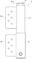
[ヒンジアセンブリの構造]
図1は、ヒンジアセンブリの正面図である。図2は、ヒンジアセンブリの平面図である。図3は、ヒンジアセンブリの断面図である。図4は、ヒンジアセンブリの要部拡大断面図である。図5は、ヒンジアセンブリの斜視図である。図6は、ヒンジアセンブリの動作状態の斜視図である。
[Hinge assembly structure]
FIG. 1 is a front view of the hinge assembly. FIG. 2 is a plan view of the hinge assembly. FIG. 3 is a cross-sectional view of the hinge assembly. FIG. 4 is an enlarged cross-sectional view of a main part of the hinge assembly. FIG. 5 is a perspective view of the hinge assembly. FIG. 6 is a perspective view of the operating state of the hinge assembly.
図1〜図4のように、ヒンジアセンブリ1は、第1、第2の外筒3、5と付勢部材としてのガススプリング7とカム筒9とピンとしてカムピン11と第1、第2の結合部として第1、第2の結合板39、41を備えている。
As shown in FIGS. 1 to 4, the
第1の外筒3は、金属、樹脂等により円筒状に形成され、筒軸方向の一端側に直状のガイド溝13a、13bを有している。ガイド溝13a、13bは、第1の外筒3の筒軸方向に沿ってカムピン11をガイドするものである。ガイド溝13a、13bの幅寸法は、カムピン11の直径と略同一であり、カムピン11がガイド溝13a、13bに沿ってガイドされながら移動できるようになっている。なお、ガイド溝13a、13bは、カムピン11を目的に機能に沿ってガイドすればよく、直状に限らず、湾曲状、S字状、L字状など、種々設定することができる。
The first
第1の外筒3の一端には、内径部に係止用の段部3aが形成されている。第1の外筒3の他端の内径部には、取り付けようの雌ネジ部15が形成されている。
At one end of the first
第2の外筒5は、金属、樹脂等により円筒状に形成され、第2の外筒5の内径は、第1の外筒3の外径と略同一に形成され、第1の外筒3の一端側に外嵌されている。第2の外筒5は、第1の外筒3に対して相対回転自在である。
The second
第2の外筒5は、第1の外筒3のガイド溝13a、13bを覆うと共にカム筒9に後述のように一体的に結合されている。
The second
ガススプリング7は、基部であるシリンダ17及びこのシリンダ17に対し可動部としてピストンロッド19を有している。ガススプリング7は、空気などのガスの圧縮反力により付勢力を発生する。つまり、ピストンロッド19が押圧されることで付勢力を蓄えるようにシリンダ17内へ移動してシリンダ17内のピストンを移動させ、押圧が開放されると付勢力でピストンを介して移動を戻し、シリンダ17から伸張する。なお、付勢部材として、ガススプリング7に代えてコイルスプリング等を用いることもできる。
The gas spring 7 has a
本実施例において、ガススプリング7は、付勢力によるピストンロッド19の移動の戻り側にスローダウン機能部を備えている。スローダウン機能部は、例えばシリンダ17内に油圧用のピストンが追加して備えられ、ピストンロッド19が伸張しきる前に油圧用のピストンとシリンダ17との間に作動油を閉じ込め、油圧用のピストンのオリフィスを作動油が通過することでスローダウン機能を発揮させるようなものである。但し、スローダウン機能部の構造は限定されるものではなく、摩擦力や粘性を利用した構成などにすることもできる。
In this embodiment, the gas spring 7 has a slow-down function part on the return side of the movement of the
ガススプリング7は、第1の外筒3内に同軸状に配置されている。ガススプリング7の基部側であるシリンダ17側は、第1の外筒3にナット21により結合固定されている。
The gas spring 7 is arranged coaxially in the first
ナット21には、外周面の軸方向一側に六角頭21aが形成され、同他側外周に雄ネジ部23が形成され、軸方向他側の軸心部に雌ネジ部25が形成されている。
The
ガススプリング7のシリンダ17端面には、雄ネジ部27が形成されている。この雄ネジ部27にナット21の雌ネジ部25が螺合してガススプリング7の端部に取り付け用のナット21が結合されている。
A
ナット21は、雄ネジ部23が第1の外筒3の雌ネジ部15に螺合している。
In the
従って、ナット21に結合されたガススプリング7がナット21を介して第1の外筒3に締結固定されている。第1の外筒3に対するナット21の締結は、六角頭21aに係合させた工具により行うことができる。
Accordingly, the gas spring 7 coupled to the
なお、ナット21は、ガススプリング7に一体に形成することもできる。この場合、ガススプリング7の端面に六角凹部を形成し、この六角凹部に六角レンチを係合させてガススプリング7を第1の外筒3に締結結合する構成にすることもできる。
Note that the
係合のための六角頭21aや六角凹部は、工具を係合させて締結作業ができればよく、四角等、その他の係合構造にすることもできる。ガススプリング7の雄ネジ部27を係合構造の一例として六角軸とし、ナット21の軸心部に貫通する六角穴に嵌合させる構造にすることもできる。この六角穴に外部からレンチを係合させて第1の外筒3に対するナット21の締結を行なわせることができる。
The
カム筒9は、断面円形の筒状に形成され、一対のカム溝29a、29bが形成されている。カム溝29a、29bは、カム筒9のほぼ半周で同方向に同一形状で螺旋状に形成されている。カム溝29a、29bの設定により特性を簡単に変更することができる。例えば、第1の外筒3に対するカム筒9の相対回転において、最後の10°のみでガススプリング7の反力をカムピン11に働かせる設定等とすることができる。
The
カム溝29a、29bは、ガイド溝13a、13bに一部が重なるように形成されている。カム溝29a、29bの幅寸法は、カムピン11の直径と略同一であり、カムピン11がカム溝29a、29bに倣って相対移動できるようになっている。カム溝29a、29bの筒軸方向の両端部は、ガイド溝13a、13bの筒軸方向の両端部に一致している。
The
カム筒9は、外径が第1の外筒3の内径に略一致して形成され、第1の外筒3の内周に隙間無く嵌合している。カム筒9には、一端部9aの外周面の径が小さくなるように段部9bが形成されている。カム筒9の一端部9aは、第1の外筒3の端部に隙間無く嵌合し、段部9bが、第1の外筒3の段部3aに筒軸方向に係合している。
The
第2の外筒5の一端部5aは、内径側に相対的に厚肉に形成されている。この第2の外筒5の一端部5aは、カム筒9の一端側外面に嵌合し、第1の外筒3の端面に筒軸方向に突き当たっている。第2の外筒5の一端部5aとカム筒9の一端部9aとに頭付きの結合ピン31が貫通し、ボルト33により締結されている。結合ピン31及びボルト33の締結により第2の外筒5の一端部5aとカム筒9の一端部9aとが一体的に締結結合されている。
One
かかる結合によりカム筒9が第1の外筒3の内周面に嵌合し第2の外筒5が第1の外筒3の一端側に外嵌され、第1の外筒3の一端側がガイド溝13a、13bを含めて第2の外筒5により覆われている。但し、ガイド溝13a、13bが第2の外筒5から露出する構造でも良い。カム筒9及び第2の外筒5は、第1の外筒3に対し筒軸周りに相対回転自在である。
With this connection, the
第2の外筒5の端部は、樹脂製などのカバー35により閉止されている。
The end of the second
カムピン11は、両端部が、ガイド溝13a、13b及びカム溝29a、29bの重なり部分で双方に嵌合している。図示の状態では、ピストンロッド19の伸張状態でガイド溝13a、13b及びカム溝29a、29bの一端が重なっている。
Both ends of the
カムピン11には、二股のクレビス37が係合している。クレビス37は、基部がピストンロッド19の先端に一体的に固定されている。クレビス37は、ガススプリング7のピストンロッド19がカムピン11から押圧力を受けると共にピストンロッド19からカムピン11に反力を伝達することができる。且つクレビス37によりカムピン11からピストンロッド19を離脱させてガススプリング7を筒軸方向に引き抜くことを可能とするものである。
A
従って、同様の機能を有する限り、ピストンロッド19とカムピン11との結合をクレビス37以外の構造により行わせることができる。ガススプリング7を筒軸方向に引き抜く構造としないときは、ピストンロッド19とカムピン11とを離脱不能に結合して両者の連動を行なわせることもできる。
Therefore, as long as it has the same function, the
このため、図1、図2の状態からカム筒9の筒軸周りの回転によりカム溝29a、29bの螺旋構造によりカムピン11が駆動される。この駆動によりカムピン11は、ガイド溝13a、13bに沿って一方向であるガススプリング7へ向って移動する。
For this reason, the
カムピン11の移動によりクレビス37を介してピストンロッド19が押圧を受ける。この押圧力でピストンロッド19がシリンダ17内へ収縮移動し、ガススプリング7が付勢力を蓄える。
The
ピストンロッド19は、押圧力が開方されるとガススプリング7が蓄えた付勢力により移動が戻される。ピストンロッド19の移動が戻ってシリンダ17から伸張するとクレビス37を介してカムピン11の移動が戻される。
When the pressing force is opened, the
第1の外筒3の他端側の外面に、取り付け用の第1の結合部として第1の結合板39が固定して設けられ、第2の外筒5の外面に、取り付け用の第2の結合部として第2の結合板41が固定して設けられている。
A
本実施例では、ガススプリング7が付勢力を開放した図1〜図4の状態で第1、第2の結合板39、41が同一側に位置する。但し、第1、第2の結合板39、41の第1、第2の外筒3、5に対する配置状態は自由である。
In the present embodiment, the first and
[ヒンジアセンブリの作用]
玄関扉等への取り付けは、例えば図5の第1の結合板39を玄関の開口側にビスなどにより取り付け、第2の結合板41を玄関の扉側にビスなどにより取り付ける。
[Operation of hinge assembly]
For example, the
扉を開くと連動して図6のように第2の結合板41が第1の結合板39に対して筒軸周りに旋回し、第2の外筒5が第1の外筒3に対して相対回転する。第2の外筒5が相対回転すると結合ピン31を介してカム筒9が筒軸周りに回転し、前記のようにカムピン11の移動でガススプリング7が付勢力を蓄える。
When the door is opened, the
図1〜図6のように、カム筒9は、カムピン11がガイド溝13a、13bの端部に当接するまで第1の外筒3に対して相対回転することができる。このカム筒9の相対回転の限界位置まで扉を開くことができる。但し、カム溝29a、29bの端部に周方向に連続する溝を設けることでカムピン11を移動させることなく周方向溝にカムピン11を相対的に移行させ、扉をさらに開く構成にすることもできる。
As shown in FIGS. 1 to 6, the
本実施例では、扉を開いてカムピン11がガイド溝13a、13bの何れの位置にあるときでも、扉から手を離すとガススプリング7に蓄えられた付勢力によりピストンロッド19が伸張し、カムピン11からカム溝29a、29bが駆動力を受けてカム筒9が逆回転し、扉が自動的に閉じられる。
In this embodiment, when the door is opened and the
扉が閉止される直前では、ガススプリング7がスローダウン機能を発揮し、カムピン11の移動が緩衝され、扉が閉じ位置まで静かに閉じられる。
Immediately before the door is closed, the gas spring 7 exhibits a slow-down function, the movement of the
ガススプリング7の特性を変更するときは、ガススプリング7を取り外して他の特性のガススプリング7を取り付ける。 When changing the characteristics of the gas spring 7, the gas spring 7 is removed and the gas spring 7 having other characteristics is attached.
ガススプリング7の取り外しは、六角レンチをナット21の六角頭21aに係合させ、ナット21を第1の外筒3から離脱させる。ナット21を螺脱回転させるとき、ピストンロッド19とシリンダ17との間が相対回転する。或いは、ピストンロッド19とクレビス37との間を相対回転自由に結合する構造とすることでガススプリング7をナット21と共に回転させて取り外すことができる。この取り外しに際し、クレビス37は、ピストンロッド19に付随して引き抜かれる。
To remove the gas spring 7, the hex wrench is engaged with the
この取り外しによりガススプリング7を異なる特性のものに交換し、逆の手順により第1の外筒3内に再配置することで、ヒンジアセンブリ1の特性を簡単に変更することができる。
By replacing the gas spring 7 with a different characteristic by this removal and rearranging the gas spring 7 in the first
カム溝29a、29bの仕様を変更するときは、カム筒9の交換により行なう。
When the specifications of the
カム筒9の交換に際しては、ボルト33を螺脱して結合ピン31を取り外す。
When the
第2の外筒5を第1の外筒3から筒軸方向に引き抜き、カムピン11をピン軸方向に引き抜きガイド溝13a、13b及びカム溝29a、29bから離脱させる。
The second
一方、前記のようにしてガススプリング7を取り外し、カム筒9を第1の外筒3の一端側から引き抜く。
On the other hand, the gas spring 7 is removed as described above, and the
カム溝29a、29bの異なる仕様のカム筒9を第1の外筒3の一端側から挿入して取り付け、逆の手順で各部を組付け、カム筒9の交換を完了する。
The
従って、カム溝29a、29bの仕様も簡単に変えることができる。
Accordingly, the specifications of the
[実施例の効果]
こうして、油圧抵抗が働く機能の備わったガススプリングを使用するため一つのヒンジアセンブリで自閉機能とスローダウン機能とを兼ね備えることができる。このため、自閉機能とスローダウン機能とを分離した構造に比較して構造をシンプルにし、安価に製造することもできる。
[Effect of Example]
Thus, since the gas spring having a function of hydraulic resistance is used, one hinge assembly can have both a self-closing function and a slow-down function. For this reason, compared with the structure which separated the self-closing function and the slow-down function, the structure can be simplified and can be manufactured at low cost.
また、ガススプリングを使用しているため、構造や部品の変更無しにガス反力調整のみであらゆる重さの扉に幅広く対応することが可能となる。 In addition, since a gas spring is used, it is possible to deal with a wide range of doors with any weight by adjusting the gas reaction force without changing the structure and parts.
但し、ガススプリングは、油圧抵抗が働く機能(スローダウン機能)を備えない構造のものを使用することも可能である。 However, it is also possible to use a gas spring having a structure that does not have a function (slow down function) in which hydraulic resistance works.
第2の結合板41が固定される第2の外筒部5は、カム筒9に結合されてカム筒9及び第2の外筒5により第1の外筒3の一端側を挟むように嵌合結合されて第1、第2の外筒3、5の一体性が強化され、第1、第2の結合板39、41間の動作を確実に行なわせることができる。
The second
ヒンジアセンブリ1は、第1の外筒3とカム筒9及び第2の外筒5とガススプリング7とから主に構成され、構造が簡単であり、安価に製造することができる。
The
ガイド溝13a、13b及びカム溝29a、29bを第2の外筒5で覆うことができ、ガイド溝13a、13b及びカム溝29a、29bを大きく形成することができ、種々の特性の溝設定を容易に行わせることができる。
The
カム筒9を交換し、カム溝29a、29bの特性を変更することもできる。従って、カム溝29a、29bの設定により扉の全開側で保持機能を持たせる構造をとることも容易である。
The
1 ヒンジアセンブリ
3 第1の外筒
5 第2の外筒
7 ガススプリング(付勢部材)
9 カム筒
11 カムピン(ピン)
13a、13b ガイド溝
17 シリンダ(基部)
19 ピストンロッド(可動部)
29a、29b カム溝
39 第1の結合板(第1の結合部)
41 第2の結合板(第2の結合部)
DESCRIPTION OF
9
13a,
19 Piston rod (movable part)
29a,
41 2nd coupling board (2nd coupling | bond part)
Claims (4)
前記第1の外筒は、筒軸方向の一端側にガイド溝を有し、
前記第2の外筒は、前記第1の外筒の一端側に外嵌され、
前記付勢部材は、基部及び可動部を有して前記第1の外筒に同軸状に配置され、
前記基部は、前記第1の外筒の他端側に結合され、
前記可動部は、前記基部に対し押圧されるように移動し押圧が開放されると付勢力で移動を戻し、
前記カム筒は、前記第1の外筒の一端側に同軸状に配置されると共に前記第2の外筒に一体的に結合され、
前記カム筒は、前記ガイド溝に交差して一部が重なるカム溝を有し、
前記ピンは、前記ガイド溝及びカム溝が重なる部分で双方に嵌合し、
前記第1の外筒の他端側の外面に、取り付け用の前記第1の結合部が設けられると共に前記第2の外筒の外面に、取り付け用の前記第2の結合部が設けられ、
前記第2の結合部から受けた回転力で前記第2の外筒及び前記カム筒が前記第1の外筒に対して相対回転すると前記ピンが前記カム溝に駆動されつつ前記ガイド溝を一方向に移動して前記可動部の移動が行われ且つ前記押圧が開放されて前記付勢力により前記可動部の移動が戻ると前記ピンの移動が戻って前記カム溝を駆動し前記カム筒及び前記第2の外筒を介して前記第2の結合部の回転を戻すように連動構成された、
ことを特徴とするヒンジアセンブリ。 A hinge assembly including first and second outer cylinders, a biasing member, a cam cylinder, a pin, and first and second coupling portions,
The first outer cylinder has a guide groove on one end side in the cylinder axis direction,
The second outer cylinder is fitted on one end side of the first outer cylinder,
The biasing member has a base portion and a movable portion and is coaxially disposed on the first outer cylinder,
The base is coupled to the other end of the first outer cylinder;
The movable part moves so as to be pressed against the base, and when the pressure is released, the movable part returns with a biasing force,
The cam cylinder is coaxially disposed on one end side of the first outer cylinder and is integrally coupled to the second outer cylinder,
The cam cylinder has a cam groove that intersects the guide groove and partially overlaps,
The pin fits both at the portion where the guide groove and cam groove overlap,
The first coupling part for attachment is provided on the outer surface on the other end side of the first outer cylinder, and the second coupling part for attachment is provided on the outer surface of the second outer cylinder,
When the second outer cylinder and the cam cylinder rotate relative to the first outer cylinder by the rotational force received from the second coupling portion, the pin is driven by the cam groove and the guide groove is moved to the same position. When the movable part is moved by moving in the direction and the pressing is released and the movement of the movable part is returned by the urging force, the movement of the pin is returned to drive the cam groove and the cam cylinder and Configured to interlock the rotation of the second coupling portion through the second outer cylinder,
A hinge assembly characterized by that.
前記第2の外筒は、前記ガイド溝を覆う、
ことを特徴とするヒンジアセンブリ。 The hinge assembly of claim 1, comprising:
The second outer cylinder covers the guide groove;
A hinge assembly characterized by that.
前記付勢部材は、前記基部がシリンダであり、前記可動部がピストンロッドであり、ガスの圧縮反力により前記付勢力を発生するガススプリングである、
ことを特徴とするヒンジアセンブリ。 A hinge assembly according to claim 1 or 2, wherein
The urging member is a gas spring in which the base is a cylinder, the movable part is a piston rod, and the urging force is generated by a compression reaction force of gas.
A hinge assembly characterized by that.
前記付勢部材は、前記付勢力による前記可動部の移動の戻り側にスローダウン機能部を備えた、
ことを特徴とするヒンジアセンブリ。 The hinge assembly according to any one of claims 1 to 3,
The biasing member includes a slow-down function part on a return side of the movement of the movable part by the biasing force.
A hinge assembly characterized by that.
Priority Applications (1)
| Application Number | Priority Date | Filing Date | Title |
|---|---|---|---|
| JP2016247466A JP6765716B2 (en) | 2016-12-21 | 2016-12-21 | Hinge assembly |
Applications Claiming Priority (1)
| Application Number | Priority Date | Filing Date | Title |
|---|---|---|---|
| JP2016247466A JP6765716B2 (en) | 2016-12-21 | 2016-12-21 | Hinge assembly |
Publications (2)
| Publication Number | Publication Date |
|---|---|
| JP2018100543A true JP2018100543A (en) | 2018-06-28 |
| JP6765716B2 JP6765716B2 (en) | 2020-10-07 |
Family
ID=62715073
Family Applications (1)
| Application Number | Title | Priority Date | Filing Date |
|---|---|---|---|
| JP2016247466A Active JP6765716B2 (en) | 2016-12-21 | 2016-12-21 | Hinge assembly |
Country Status (1)
| Country | Link |
|---|---|
| JP (1) | JP6765716B2 (en) |
Cited By (1)
| Publication number | Priority date | Publication date | Assignee | Title |
|---|---|---|---|---|
| CN108868412A (en) * | 2018-07-16 | 2018-11-23 | 佛山市远阳五金制品有限公司 | A kind of self-return glass door safety clamp |
Citations (3)
| Publication number | Priority date | Publication date | Assignee | Title |
|---|---|---|---|---|
| JP2002303072A (en) * | 2001-04-09 | 2002-10-18 | Kazu Sawa | Buffer function attached automatic door closing mechanism and its hinge |
| JP2003278431A (en) * | 2002-03-07 | 2003-10-02 | Fu Luong Hi-Tech Co Ltd | Automatic closing door hinge |
| US20160237730A1 (en) * | 2013-10-04 | 2016-08-18 | In & Tec S.R.L. | Hinge device for doors, shutters or the like |
-
2016
- 2016-12-21 JP JP2016247466A patent/JP6765716B2/en active Active
Patent Citations (3)
| Publication number | Priority date | Publication date | Assignee | Title |
|---|---|---|---|---|
| JP2002303072A (en) * | 2001-04-09 | 2002-10-18 | Kazu Sawa | Buffer function attached automatic door closing mechanism and its hinge |
| JP2003278431A (en) * | 2002-03-07 | 2003-10-02 | Fu Luong Hi-Tech Co Ltd | Automatic closing door hinge |
| US20160237730A1 (en) * | 2013-10-04 | 2016-08-18 | In & Tec S.R.L. | Hinge device for doors, shutters or the like |
Cited By (1)
| Publication number | Priority date | Publication date | Assignee | Title |
|---|---|---|---|---|
| CN108868412A (en) * | 2018-07-16 | 2018-11-23 | 佛山市远阳五金制品有限公司 | A kind of self-return glass door safety clamp |
Also Published As
| Publication number | Publication date |
|---|---|
| JP6765716B2 (en) | 2020-10-07 |
Similar Documents
| Publication | Publication Date | Title |
|---|---|---|
| JP6074065B2 (en) | Actuating drive for moving movable furniture parts | |
| US8108969B2 (en) | Checker-equipped door hinge device for vehicle | |
| US20100162839A1 (en) | Driving Device | |
| EP3222806A1 (en) | Door opening and closing device for vehicle | |
| JP5135232B2 (en) | Hinge part | |
| JP5535580B2 (en) | Automatic door hinge | |
| JP2008537071A (en) | Wheel brake | |
| JP2019090258A (en) | Door check device | |
| JP6326187B2 (en) | Door closing brake device | |
| JP2007145055A (en) | Automobile door hinge device | |
| JP2007145055A5 (en) | ||
| JP2018100543A (en) | Hinge assembly | |
| JP6345593B2 (en) | Opening and closing body operating device | |
| JP5996848B2 (en) | Open / close drive device | |
| JP2011121492A5 (en) | ||
| US20220162897A1 (en) | Automatic door operator | |
| JP4829713B2 (en) | Brake device for opening closing member and opening closing member having the same | |
| JP5111894B2 (en) | Unit brake | |
| JP5588652B2 (en) | Sliding door closer | |
| US20070000087A1 (en) | Door hinge | |
| JP6047371B2 (en) | Open / close drive device | |
| JP6617943B2 (en) | Pivot hinge with closing mechanism | |
| JP3550546B2 (en) | Hinge mechanism | |
| JP3114392U (en) | Door opening and closing device | |
| WO2010134211A1 (en) | Hinge apparatus |
Legal Events
| Date | Code | Title | Description |
|---|---|---|---|
| A621 | Written request for application examination |
Free format text: JAPANESE INTERMEDIATE CODE: A621 Effective date: 20191107 |
|
| A977 | Report on retrieval |
Free format text: JAPANESE INTERMEDIATE CODE: A971007 Effective date: 20200820 |
|
| TRDD | Decision of grant or rejection written | ||
| A01 | Written decision to grant a patent or to grant a registration (utility model) |
Free format text: JAPANESE INTERMEDIATE CODE: A01 Effective date: 20200901 |
|
| A61 | First payment of annual fees (during grant procedure) |
Free format text: JAPANESE INTERMEDIATE CODE: A61 Effective date: 20200911 |
|
| R150 | Certificate of patent or registration of utility model |
Ref document number: 6765716 Country of ref document: JP Free format text: JAPANESE INTERMEDIATE CODE: R150 |
|
| R250 | Receipt of annual fees |
Free format text: JAPANESE INTERMEDIATE CODE: R250 |
|
| R250 | Receipt of annual fees |
Free format text: JAPANESE INTERMEDIATE CODE: R250 |