JP4916618B2 - Coating method of sprayed metal layer surface - Google Patents
Coating method of sprayed metal layer surface Download PDFInfo
- Publication number
- JP4916618B2 JP4916618B2 JP2001050402A JP2001050402A JP4916618B2 JP 4916618 B2 JP4916618 B2 JP 4916618B2 JP 2001050402 A JP2001050402 A JP 2001050402A JP 2001050402 A JP2001050402 A JP 2001050402A JP 4916618 B2 JP4916618 B2 JP 4916618B2
- Authority
- JP
- Japan
- Prior art keywords
- metal layer
- sprayed metal
- paint
- coating
- sprayed
- Prior art date
- Legal status (The legal status is an assumption and is not a legal conclusion. Google has not performed a legal analysis and makes no representation as to the accuracy of the status listed.)
- Expired - Fee Related
Links
- 229910052751 metal Inorganic materials 0.000 title claims description 63
- 239000002184 metal Substances 0.000 title claims description 63
- 238000000576 coating method Methods 0.000 title claims description 38
- 239000003973 paint Substances 0.000 claims description 37
- 239000011248 coating agent Substances 0.000 claims description 34
- 238000010422 painting Methods 0.000 claims description 17
- 238000001035 drying Methods 0.000 claims description 10
- 238000000034 method Methods 0.000 claims description 10
- 238000005507 spraying Methods 0.000 claims description 6
- 239000002904 solvent Substances 0.000 claims description 5
- 229920005749 polyurethane resin Polymers 0.000 claims description 2
- 238000010438 heat treatment Methods 0.000 description 12
- 239000000463 material Substances 0.000 description 6
- 239000003795 chemical substances by application Substances 0.000 description 2
- 238000010790 dilution Methods 0.000 description 2
- 239000012895 dilution Substances 0.000 description 2
- 238000005187 foaming Methods 0.000 description 2
- JEIPFZHSYJVQDO-UHFFFAOYSA-N iron(III) oxide Inorganic materials O=[Fe]O[Fe]=O JEIPFZHSYJVQDO-UHFFFAOYSA-N 0.000 description 2
- 239000004814 polyurethane Substances 0.000 description 2
- 229920002635 polyurethane Polymers 0.000 description 2
- 239000011527 polyurethane coating Substances 0.000 description 2
- 230000002265 prevention Effects 0.000 description 2
- 238000007789 sealing Methods 0.000 description 2
- 238000004904 shortening Methods 0.000 description 2
- 239000007921 spray Substances 0.000 description 2
- 229910000611 Zinc aluminium Inorganic materials 0.000 description 1
- 229910045601 alloy Inorganic materials 0.000 description 1
- 239000000956 alloy Substances 0.000 description 1
- HXFVOUUOTHJFPX-UHFFFAOYSA-N alumane;zinc Chemical compound [AlH3].[Zn] HXFVOUUOTHJFPX-UHFFFAOYSA-N 0.000 description 1
- 230000007423 decrease Effects 0.000 description 1
- 230000002950 deficient Effects 0.000 description 1
- 230000000694 effects Effects 0.000 description 1
- 238000010285 flame spraying Methods 0.000 description 1
- 238000002156 mixing Methods 0.000 description 1
- 239000011148 porous material Substances 0.000 description 1
- 238000007751 thermal spraying Methods 0.000 description 1
- XLYOFNOQVPJJNP-UHFFFAOYSA-N water Substances O XLYOFNOQVPJJNP-UHFFFAOYSA-N 0.000 description 1
Images
Landscapes
- Application Of Or Painting With Fluid Materials (AREA)
- Coating By Spraying Or Casting (AREA)
Description
【0001】
【発明の属する技術分野】
本発明は、被塗物の溶射金属層の表面に塗装を行う溶射金属層表面の塗装方法に関するものである。
【0002】
【従来の技術】
従来、溶射金属層の表面に塗装を行う場合には、特公昭52−10406号に示されるように、専用の封孔処理塗装を行うことが多い。
【0003】
【発明が解決しようとする課題】
しかしながら、溶射金属層の表面に2液性ポリウレタン塗料の塗装のみを膜厚30μm程行った場合には、気泡が表面に残り、その気泡が潰れることで水等が浸入し、封孔性能が低下し、防錆寿命を短くする問題点があった。そのため、専用の下塗り塗装を行ったり、非常に希釈した塗料を前もって塗ったり、発泡を少なくする方法が取られていた。
【0004】
また、2液性ポリウレタン塗料以外の塗料を用いる場合においても、乾燥時間を短くするため、塗装後、焼き付け乾燥装置等の加熱装置を用いて、塗料を硬化させることが多いが、この場合には溶射金属層の表面に塗料を塗布した後、焼き付け乾燥装置等で加熱すると、多孔質な溶射金属層の内部にある空気が押し出され、それが加熱されて硬化し、気泡が表面に残る問題点があった。
【0005】
常温乾燥で用いる塗料の場合には、その影響がより一層大きくなり、外観上不具合な結果となる問題点があった。
【0006】
専用の下塗り塗装を施すことは、塗装時間、塗料費等コストを上げる要因となっていた。
【0007】
本発明の目的は、溶射金属層の表面に、安価に、発泡させることなく塗料を塗装できる溶射金属層表面の塗装方法を提供することにある。
【0008】
【課題を解決するための手段】
本発明は、被塗物の溶射金属層の表面に速乾性を有する常温乾燥塗料を吹き付けて塗装を施す溶射金属層表面の塗装方法を改良するものである。
【0009】
本発明に係る溶射金属層表面の塗装方法においては、常温乾燥塗料として揮発性溶剤を含む塗料を用い、被塗物の溶射金属層を、該溶射金属層に吹き付ける塗料の温度より高い温度まで加熱した後、溶射金属層の温度よりも低温の塗料を溶射金属層の表面に吹き付けることを特徴とする。
【0010】
このように被塗物の溶射金属層を加熱することで、多孔質な溶射金属層の内部にある空気が加熱された状態になり、この状態で溶射金属層の温度より低温の塗料を吹き付けることで、多孔質な溶射金属層の内部にある空気は急激に冷やされて収縮し、塗料は多孔質な溶射金属層にしみこみ、同時に溶射金属層の内部に存在する空気を外部に押し出す。塗料が乾く前に内部の空気が押し出されることで、気泡が残らず、きれいな表面の塗装が可能となる。
【0011】
この場合、加熱した溶射金属層の表面の温度は、溶射金属層に吹き付ける塗料の温度より10〜30℃高くなっていることが好ましい。
【0012】
また、塗料としては、希釈シンナーを揮発性溶剤として含むポリウレタン樹脂からなる塗料を用いることが好ましい。
【0013】
【発明の実施の形態】
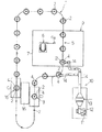
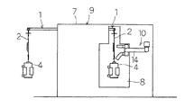
図1及び図2は本発明に係る溶射金属層表面の塗装方法を実施する塗装装置の実施の形態の一例を示したもので、図1は平面図、図2は図1の縦断面図である。
【0014】
本例の塗装装置は、図示のようなループ状にして所定の高さで架設されたトロリーコンベア1を備え、このコンベア1には所定間隔でハンガー2が支持されている。これらハンガー2には、着荷位置3で作業者により金属製の変圧器ケースの如き被塗物4が順次吊り下げられるようになっている。各被塗物4の表面は、溶射金属層で覆われている。このような被塗物4は、コンベア1の走行により塗装位置5に搬送され、塗装ロボット6の塗装ガン6aで溶射金属層の表面に塗装が行われるようになっている。塗装位置5の周囲は、塗料を閉じ込める塗装ブース7で囲まれている。塗装ブース7には、コンベア1、ハンガー2及び被塗物4が通り抜ける開口部8が設けられている。また、図示しないが塗装位置5には、塗装ガン6aで塗装を行う際に、ハンガー2を被塗物4と共に回転させるハンガー回転機構が設けられている。これら塗装ロボット6、塗装ブース7、図示しないハンガー回転機構等により塗装機構9が構成されている。
【0015】
コンベア1で被塗物4を塗装位置5に搬送する前の位置に、被塗物4を加熱する加熱装置10が設けられている。この加熱装置10は、モータ11でファン12を回転して風を発生させ、この風で蒸気ヒータ13により間接的に暖められた空気をダクト14により塗装位置5の前に至った変圧器ケースの如き被塗物4まで運び、その内部に吹き出させて該被塗物4を加熱し、被塗物4の表面に溶射されている溶射金属層の表面を、該溶射金属層の表面に塗装する前述した塗料の温度より高温に加熱するようになっている。
【0016】
コンベア1の着荷位置3に隣接した箇所は、脱荷位置15となっていて作業者が塗装済みの被塗物4をハンガー2から外されるようになっている。本例では、着荷位置3と脱荷位置15との間に作業台16が設置され、この作業台16上に載った作業者が着荷や脱荷の作業を行うようになっている。図示しないが着荷位置3と脱荷位置15とには、被塗物4をハンガー2に向けて持ち上げたり、被塗物4をハンガー2から下ろしたりするリフターが設置されている。
【0017】
次に、このような塗装装置による塗装方法について説明する。
【0018】
この塗装工程の前に、変圧器ケースの如き被塗物4は溶射工程でその表面に溶射を行い、溶射金属層で覆う。溶射は、アーク溶射またはフレーム溶射等により行う。例えば、アーク溶射は、2本の金属溶線間に14〜25Vの電圧を印加し、2本の金属溶線の先端にて発生させるアークにてこれら金属溶線を溶かして溶滴とし、これら溶滴を後方よりの圧縮気体の高速の流れに乗せて被塗物4まで搬送し、付着させて溶射金属層を形成し、防錆ならびに防食処理層とする。溶射金属層は、例えば溶射金属としての亜鉛−アルミニウム合金を100 μmの膜厚で施す。この溶射金属層は、孔をもたない被膜とはならず、多孔質な被膜となっている。
【0019】
このようにして表面に溶射金属層を有する被塗物4を、着荷位置3で作業者によりハンガー2に順次吊り下げる。ハンガー2で吊り下げられた被塗物4をコンベア1で搬送し、塗装位置5の前に達すると、加熱装置10のダクト14から過熱された空気を該被塗物4の内部に吹き込み、該被塗物4を加熱する。加熱する熱風の温度は、例えば約70〜100 ℃程度が望ましい。加熱された溶射金属層の温度は、塗布する塗料の温度より10〜30℃程度高くする。
【0020】
加熱された被塗物4が塗装位置5に達すると、被塗物4を図示しないハンガー回転機構でハンガー2を被塗物4と共に回転させつつ、塗装ロボット6の塗装ガン6aで溶射金属層の表面に常温の塗料を吹き付けて塗装を施す。
【0021】
塗装する塗料としては、例えば熱乾燥を必要としない常温乾燥性で速乾性の2液性ポリウレタン塗料を用いる。2液性ポリウレタン塗料は、塗料主剤、硬化剤ならびに希釈シンナーよりなり、これらを適当な混合比で混ぜ合わせて使用する。速乾性とは、希釈シンナーの揮発性が高く、塗装表面が早く乾くことで、指触可能乾燥時間を短くした塗料をいう。常温乾燥塗料とは、塗装後、特別に加熱することなく常温で乾燥する塗料をいう。
【0022】
このように被塗物4の溶射金属層を加熱することで、多孔質な溶射金属層の内部にある空気が加熱された状態になり、この状態で溶射金属層の温度より低温の塗料を吹き付けることで、多孔質な溶射金属層の内部にある空気は急激に冷やされて収縮し、塗料は多孔質な溶射金属層にしみこみ、同時に溶射金属層の内部に存在する空気を外部に押し出す。塗料が乾く前に内部の空気が押し出されることで、気泡が残らず、きれいな表面の塗装が可能となる。
【0023】
塗料にシンナー等の揮発性溶剤を使わない場合は、加熱装置10の熱源として電熱ヒータや遠赤外線ヒータを用いることができる。
【0024】
【発明の効果】
本発明に係る溶射金属層表面の塗装方法においては、被塗物の溶射金属層を加熱するので、多孔質な溶射金属層の内部にある空気が加熱された状態になり、この状態で溶射金属層の温度より低温の塗料を吹き付けることで、多孔質な溶射金属層の内部にある空気は急激に冷やされて収縮し、塗料は多孔質な溶射金属層にしみこみ、同時に溶射金属層の内部に存在する空気を外部に押し出し、気泡が残らないきれいな表面の塗装を行うことができる。
【図面の簡単な説明】
【図1】 本発明に係る溶射金属層表面の塗装方法を実施する塗装装置の実施の形態の一例を示した平面図である。
【図2】 図1の縦断面図である。
【符号の説明】
1 トロリーコンベア
2 ハンガー
3 着荷位置
4 被塗物
5 塗装位置
6 塗装ロボット
6a 塗装ガン
7 塗装ブース
8 開口部
9 塗装機構
10 加熱装置
11 モータ
12 ファン
13 蒸気ヒータ
14 ダクト
15 脱荷位置
16 作業台[0001]
BACKGROUND OF THE INVENTION
The present invention relates to a method for coating the surface of a sprayed metal layer in which the surface of the sprayed metal layer of an object to be coated is coated.
[0002]
[Prior art]
Conventionally, when coating is performed on the surface of a sprayed metal layer, a dedicated sealing treatment coating is often performed as disclosed in Japanese Patent Publication No. 52-10406.
[0003]
[Problems to be solved by the invention]
However, when only a two-component polyurethane coating is applied to the surface of the sprayed metal layer to a thickness of about 30 μm, air bubbles remain on the surface, and the air bubbles are crushed so that water or the like enters and the sealing performance decreases. However, there is a problem of shortening the rust prevention life. For this reason, special undercoats have been applied, highly diluted paints are applied in advance, or foaming is reduced.
[0004]
Also, when using paints other than two-component polyurethane paints, in order to shorten the drying time, the paint is often cured using a heating device such as a baking / drying device after painting. After applying the paint on the surface of the sprayed metal layer and heating it with a baking dryer, the air inside the porous sprayed metal layer is pushed out and heated to harden, leaving bubbles on the surface. was there.
[0005]
In the case of a paint used for drying at room temperature, the influence is further increased, and there is a problem that results in a defective appearance.
[0006]
The application of a dedicated undercoat has been a factor in increasing costs such as coating time and paint costs.
[0007]
An object of the present invention is to provide a method for coating a surface of a sprayed metal layer, which can be applied on the surface of the sprayed metal layer at low cost without foaming.
[0008]
[Means for Solving the Problems]
The present invention improves the coating method of the surface of the sprayed metal layer in which the coating is performed by spraying a room temperature dry paint having quick drying properties on the surface of the sprayed metal layer of the object to be coated.
[0009]
In the method of coating the surface of the sprayed metal layer according to the present invention, a paint containing a volatile solvent is used as a room temperature dry paint, and the sprayed metal layer of the object to be coated is heated to a temperature higher than the temperature of the paint sprayed on the sprayed metal layer. Then, a coating material having a temperature lower than that of the sprayed metal layer is sprayed onto the surface of the sprayed metal layer.
[0010]
By heating the sprayed metal layer of the object to be coated in this way, the air inside the porous sprayed metal layer is heated, and in this state, a paint having a temperature lower than the temperature of the sprayed metal layer is sprayed. Thus, the air inside the porous sprayed metal layer is rapidly cooled and contracted, and the paint penetrates into the porous sprayed metal layer, and at the same time pushes the air existing inside the sprayed metal layer to the outside. Air is pushed out before the paint dries so that no bubbles remain and a clean surface can be painted.
[0011]
In this case, the surface temperature of the heated sprayed metal layer is preferably higher by 10 to 30 ° C. than the temperature of the paint sprayed on the sprayed metal layer.
[0012]
Moreover, it is preferable to use the coating material which consists of a polyurethane resin which contains dilution thinner as a volatile solvent as a coating material .
[0013]
DETAILED DESCRIPTION OF THE INVENTION
1 and 2 show an example of an embodiment of a coating apparatus for carrying out the method for coating a sprayed metal layer surface according to the present invention. FIG. 1 is a plan view and FIG. 2 is a longitudinal sectional view of FIG. is there.
[0014]
The coating apparatus of this example includes a
[0015]
A
[0016]
A location adjacent to the arrival position 3 of the
[0017]
Next, a coating method using such a coating apparatus will be described.
[0018]
Prior to this coating process, the object to be coated 4 such as a transformer case is sprayed on its surface in the spraying process and covered with a sprayed metal layer. Thermal spraying is performed by arc spraying or flame spraying. For example, in arc spraying, a voltage of 14 to 25 V is applied between two metal melt wires, and these metal melt wires are melted into droplets by an arc generated at the tips of the two metal melt wires. It is carried on the high-speed flow of the compressed gas from the rear and conveyed to the
[0019]
In this way, the
[0020]
When the
[0021]
As the coating material to be applied, for example, a two-component polyurethane coating material which is room temperature drying and quick drying which does not require heat drying is used. The two-component polyurethane paint is composed of a paint main agent, a curing agent, and a diluted thinner, and these are mixed and used at an appropriate mixing ratio. Quick-drying refers to a paint in which the dilution thinner is highly volatile and the paint surface dries quickly, shortening the drying time that can be touched. The room temperature dry paint refers to a paint that is dried at room temperature without special heating after painting.
[0022]
By thus heating the sprayed metal layer of the
[0023]
When a volatile solvent such as thinner is not used for the paint, an electric heater or a far infrared heater can be used as a heat source of the
[0024]
【Effect of the invention】
In the method of coating the surface of the sprayed metal layer according to the present invention, since the sprayed metal layer of the object to be coated is heated, the air inside the porous sprayed metal layer is heated, and in this state, the sprayed metal is heated. By spraying the paint at a temperature lower than the temperature of the layer, the air inside the porous sprayed metal layer is rapidly cooled and contracted, and the paint penetrates into the porous sprayed metal layer, and at the same time enters the inside of the sprayed metal layer. Existing air can be pushed out to paint clean surfaces without bubbles.
[Brief description of the drawings]
FIG. 1 is a plan view showing an example of an embodiment of a coating apparatus for performing a method for coating a surface of a sprayed metal layer according to the present invention.
FIG. 2 is a longitudinal sectional view of FIG.
[Explanation of symbols]
DESCRIPTION OF
Claims (2)
前記常温乾燥塗料として揮発性溶剤を含む塗料を用い、
前記被塗物の溶射金属層を、該溶射金属層に吹き付ける塗料の温度より10〜30℃高い温度まで加熱した後、前記溶射金属層の温度よりも低温の前記塗料を前記溶射金属層の表面に吹きつけることを特徴とする溶射金属層表面の塗装方法。In the method of coating the surface of the sprayed metal layer, the surface of the sprayed metal layer of the object to be coated is sprayed with a room temperature dry paint having a quick drying property.
Using a paint containing a volatile solvent as the room temperature dry paint,
After the sprayed metal layer of the object to be coated is heated to a temperature 10-30 ° C. higher than the temperature of the paint sprayed on the sprayed metal layer, the paint having a temperature lower than the temperature of the sprayed metal layer is applied to the surface of the sprayed metal layer. A method of painting a surface of a sprayed metal layer characterized by spraying on the surface.
Priority Applications (1)
| Application Number | Priority Date | Filing Date | Title |
|---|---|---|---|
| JP2001050402A JP4916618B2 (en) | 2001-02-26 | 2001-02-26 | Coating method of sprayed metal layer surface |
Applications Claiming Priority (1)
| Application Number | Priority Date | Filing Date | Title |
|---|---|---|---|
| JP2001050402A JP4916618B2 (en) | 2001-02-26 | 2001-02-26 | Coating method of sprayed metal layer surface |
Publications (3)
| Publication Number | Publication Date |
|---|---|
| JP2002248418A JP2002248418A (en) | 2002-09-03 |
| JP2002248418A5 JP2002248418A5 (en) | 2008-04-03 |
| JP4916618B2 true JP4916618B2 (en) | 2012-04-18 |
Family
ID=18911362
Family Applications (1)
| Application Number | Title | Priority Date | Filing Date |
|---|---|---|---|
| JP2001050402A Expired - Fee Related JP4916618B2 (en) | 2001-02-26 | 2001-02-26 | Coating method of sprayed metal layer surface |
Country Status (1)
| Country | Link |
|---|---|
| JP (1) | JP4916618B2 (en) |
Families Citing this family (2)
| Publication number | Priority date | Publication date | Assignee | Title |
|---|---|---|---|---|
| JP2006130384A (en) * | 2004-11-02 | 2006-05-25 | Asama Giken Co Ltd | Coating and drying method of aqueous paint and apparatus therefor |
| JP5806886B2 (en) * | 2011-09-06 | 2015-11-10 | 日本鋳鉄管株式会社 | Equipment for forming anti-corrosion coating on deformed metal pipes |
Family Cites Families (5)
| Publication number | Priority date | Publication date | Assignee | Title |
|---|---|---|---|---|
| JPH01142070A (en) * | 1987-11-30 | 1989-06-02 | Nomura Tokin:Kk | Production of pore sealed thermally sprayed layer |
| JPH0649176B2 (en) * | 1988-07-15 | 1994-06-29 | 大日本塗料株式会社 | Surface finishing method |
| JP2973449B2 (en) * | 1990-02-27 | 1999-11-08 | 石川島播磨重工業株式会社 | Metal spray coating method |
| JP2947597B2 (en) * | 1990-07-27 | 1999-09-13 | 日本油脂株式会社 | Coating method of cast product and decorative cast product obtained by the method |
| JP4493747B2 (en) * | 1999-03-31 | 2010-06-30 | 株式会社ダイヘン | Outdoor electrical equipment tank |
-
2001
- 2001-02-26 JP JP2001050402A patent/JP4916618B2/en not_active Expired - Fee Related
Also Published As
| Publication number | Publication date |
|---|---|
| JP2002248418A (en) | 2002-09-03 |
Similar Documents
| Publication | Publication Date | Title |
|---|---|---|
| AU660529B2 (en) | An enclosure for painting, and a method of enforcing evaporation from a coating on a panel surface | |
| EP1251972B1 (en) | Process for coating metallic substrate surfaces and coated surface | |
| JP4705877B2 (en) | Top coating equipment and coating method using the same | |
| JP4505736B2 (en) | Painting machine | |
| US20040253373A1 (en) | Method of powder coating | |
| JP4916618B2 (en) | Coating method of sprayed metal layer surface | |
| JPS646948Y2 (en) | ||
| JP2007222821A (en) | Paint flash-off device | |
| JPH0568916A (en) | Painting equipment | |
| JPH10249261A (en) | Coating and drying oven | |
| JP4935086B2 (en) | Coating method using rotary atomizing coating equipment | |
| JP4984654B2 (en) | Water-based paint film forming equipment | |
| JPH06432A (en) | Painted steel strip production equipment | |
| JP2006026476A (en) | Method and apparatus for cooling workpiece | |
| JP4550694B2 (en) | Painting machine | |
| JP2828648B2 (en) | Repair paint for pearl coating and its repair method | |
| JP2014023996A (en) | Method and device for applying top coat to vehicle body | |
| JP4075871B2 (en) | Painting method | |
| JP2022130780A (en) | Water-based paint film formation method and water-based paint film formation device | |
| JPH01224074A (en) | Coating and drying device for plate work | |
| JPH105683A (en) | Multi-layer coating method | |
| JP4124177B2 (en) | Painting method | |
| JP2006181499A (en) | Coating method and coating system | |
| JPS60861A (en) | Device and method for painting multiple-coat single-bake type paint | |
| JPH0256279A (en) | Painting method for synthetic resin molding |
Legal Events
| Date | Code | Title | Description |
|---|---|---|---|
| A521 | Written amendment |
Free format text: JAPANESE INTERMEDIATE CODE: A523 Effective date: 20080218 |
|
| A621 | Written request for application examination |
Free format text: JAPANESE INTERMEDIATE CODE: A621 Effective date: 20080218 |
|
| A977 | Report on retrieval |
Free format text: JAPANESE INTERMEDIATE CODE: A971007 Effective date: 20100823 |
|
| A131 | Notification of reasons for refusal |
Free format text: JAPANESE INTERMEDIATE CODE: A131 Effective date: 20100831 |
|
| A521 | Written amendment |
Free format text: JAPANESE INTERMEDIATE CODE: A523 Effective date: 20101028 |
|
| A131 | Notification of reasons for refusal |
Free format text: JAPANESE INTERMEDIATE CODE: A131 Effective date: 20110517 |
|
| A521 | Written amendment |
Free format text: JAPANESE INTERMEDIATE CODE: A523 Effective date: 20110711 |
|
| TRDD | Decision of grant or rejection written | ||
| A01 | Written decision to grant a patent or to grant a registration (utility model) |
Free format text: JAPANESE INTERMEDIATE CODE: A01 Effective date: 20120124 |
|
| A01 | Written decision to grant a patent or to grant a registration (utility model) |
Free format text: JAPANESE INTERMEDIATE CODE: A01 |
|
| A61 | First payment of annual fees (during grant procedure) |
Free format text: JAPANESE INTERMEDIATE CODE: A61 Effective date: 20120125 |
|
| FPAY | Renewal fee payment (event date is renewal date of database) |
Free format text: PAYMENT UNTIL: 20150203 Year of fee payment: 3 |
|
| R150 | Certificate of patent or registration of utility model |
Ref document number: 4916618 Country of ref document: JP Free format text: JAPANESE INTERMEDIATE CODE: R150 Free format text: JAPANESE INTERMEDIATE CODE: R150 |
|
| R250 | Receipt of annual fees |
Free format text: JAPANESE INTERMEDIATE CODE: R250 |
|
| R250 | Receipt of annual fees |
Free format text: JAPANESE INTERMEDIATE CODE: R250 |
|
| R250 | Receipt of annual fees |
Free format text: JAPANESE INTERMEDIATE CODE: R250 |
|
| LAPS | Cancellation because of no payment of annual fees |