JP4914971B2 - How to sterilize containers - Google Patents
How to sterilize containers Download PDFInfo
- Publication number
- JP4914971B2 JP4914971B2 JP2007318390A JP2007318390A JP4914971B2 JP 4914971 B2 JP4914971 B2 JP 4914971B2 JP 2007318390 A JP2007318390 A JP 2007318390A JP 2007318390 A JP2007318390 A JP 2007318390A JP 4914971 B2 JP4914971 B2 JP 4914971B2
- Authority
- JP
- Japan
- Prior art keywords
- sterilization chamber
- pressure
- sterilization
- containers
- chamber
- Prior art date
- Legal status (The legal status is an assumption and is not a legal conclusion. Google has not performed a legal analysis and makes no representation as to the accuracy of the status listed.)
- Expired - Fee Related
Links
Images


Classifications
-
- A—HUMAN NECESSITIES
- A61—MEDICAL OR VETERINARY SCIENCE; HYGIENE
- A61L—METHODS OR APPARATUS FOR STERILISING MATERIALS OR OBJECTS IN GENERAL; DISINFECTION, STERILISATION OR DEODORISATION OF AIR; CHEMICAL ASPECTS OF BANDAGES, DRESSINGS, ABSORBENT PADS OR SURGICAL ARTICLES; MATERIALS FOR BANDAGES, DRESSINGS, ABSORBENT PADS OR SURGICAL ARTICLES
- A61L2/00—Methods or apparatus for disinfecting or sterilising materials or objects other than foodstuffs or contact lenses; Accessories therefor
- A61L2/16—Methods or apparatus for disinfecting or sterilising materials or objects other than foodstuffs or contact lenses; Accessories therefor using chemical substances
- A61L2/20—Gaseous substances, e.g. vapours
- A61L2/208—Hydrogen peroxide
-
- A—HUMAN NECESSITIES
- A61—MEDICAL OR VETERINARY SCIENCE; HYGIENE
- A61L—METHODS OR APPARATUS FOR STERILISING MATERIALS OR OBJECTS IN GENERAL; DISINFECTION, STERILISATION OR DEODORISATION OF AIR; CHEMICAL ASPECTS OF BANDAGES, DRESSINGS, ABSORBENT PADS OR SURGICAL ARTICLES; MATERIALS FOR BANDAGES, DRESSINGS, ABSORBENT PADS OR SURGICAL ARTICLES
- A61L2/00—Methods or apparatus for disinfecting or sterilising materials or objects other than foodstuffs or contact lenses; Accessories therefor
- A61L2/02—Methods or apparatus for disinfecting or sterilising materials or objects other than foodstuffs or contact lenses; Accessories therefor using physical phenomena
- A61L2/04—Heat
- A61L2/06—Hot gas
- A61L2/07—Steam
-
- A—HUMAN NECESSITIES
- A61—MEDICAL OR VETERINARY SCIENCE; HYGIENE
- A61L—METHODS OR APPARATUS FOR STERILISING MATERIALS OR OBJECTS IN GENERAL; DISINFECTION, STERILISATION OR DEODORISATION OF AIR; CHEMICAL ASPECTS OF BANDAGES, DRESSINGS, ABSORBENT PADS OR SURGICAL ARTICLES; MATERIALS FOR BANDAGES, DRESSINGS, ABSORBENT PADS OR SURGICAL ARTICLES
- A61L2/00—Methods or apparatus for disinfecting or sterilising materials or objects other than foodstuffs or contact lenses; Accessories therefor
- A61L2/16—Methods or apparatus for disinfecting or sterilising materials or objects other than foodstuffs or contact lenses; Accessories therefor using chemical substances
- A61L2/18—Liquid substances or solutions comprising solids or dissolved gases
-
- B—PERFORMING OPERATIONS; TRANSPORTING
- B65—CONVEYING; PACKING; STORING; HANDLING THIN OR FILAMENTARY MATERIAL
- B65B—MACHINES, APPARATUS OR DEVICES FOR, OR METHODS OF, PACKAGING ARTICLES OR MATERIALS; UNPACKING
- B65B55/00—Preserving, protecting or purifying packages or package contents in association with packaging
- B65B55/02—Sterilising, e.g. of complete packages
- B65B55/04—Sterilising wrappers or receptacles prior to, or during, packaging
- B65B55/10—Sterilising wrappers or receptacles prior to, or during, packaging by liquids or gases
-
- A—HUMAN NECESSITIES
- A61—MEDICAL OR VETERINARY SCIENCE; HYGIENE
- A61L—METHODS OR APPARATUS FOR STERILISING MATERIALS OR OBJECTS IN GENERAL; DISINFECTION, STERILISATION OR DEODORISATION OF AIR; CHEMICAL ASPECTS OF BANDAGES, DRESSINGS, ABSORBENT PADS OR SURGICAL ARTICLES; MATERIALS FOR BANDAGES, DRESSINGS, ABSORBENT PADS OR SURGICAL ARTICLES
- A61L2202/00—Aspects relating to methods or apparatus for disinfecting or sterilising materials or objects
- A61L2202/10—Apparatus features
- A61L2202/12—Apparatus for isolating biocidal substances from the environment
- A61L2202/122—Chambers for sterilisation
-
- A—HUMAN NECESSITIES
- A61—MEDICAL OR VETERINARY SCIENCE; HYGIENE
- A61L—METHODS OR APPARATUS FOR STERILISING MATERIALS OR OBJECTS IN GENERAL; DISINFECTION, STERILISATION OR DEODORISATION OF AIR; CHEMICAL ASPECTS OF BANDAGES, DRESSINGS, ABSORBENT PADS OR SURGICAL ARTICLES; MATERIALS FOR BANDAGES, DRESSINGS, ABSORBENT PADS OR SURGICAL ARTICLES
- A61L2202/00—Aspects relating to methods or apparatus for disinfecting or sterilising materials or objects
- A61L2202/20—Targets to be treated
- A61L2202/23—Containers, e.g. vials, bottles, syringes, mail
Description
本発明は、減圧可能な滅菌室内にある1群の容器を滅菌する方法に関する。 The present invention relates to a method for sterilizing a group of containers in a sterilized chamber capable of being decompressed.
この種の方法、但しそれとは系列の点で異なる諸ステップを含む方法が、例えば特許文献1により公知である。この公知方法は、満たすべき容器が機械設備内を直線的に移動するいわゆる直線充填器の構成要素である滅菌室内で実施される。その際、滅菌中に1群の、例えば6個の容器が1つの滅菌室内に同時にある。つまり、群の全容器はいつでも当該プロセス周期の同じ位置にある。機械設備は不連続的に作動する。滅菌自体は滅菌室内で生成される低温プラズマによって行われる。 A method of this kind, but including a number of steps that differ from that of the series, is known, for example, from US Pat. This known method is carried out in a sterilization chamber which is a component of a so-called linear filling machine in which the container to be filled moves linearly in the machine equipment. In so doing, a group of, for example, six containers are simultaneously in one sterilization chamber during sterilization. That is, all containers in the group are always at the same position in the process cycle. Mechanical equipment operates discontinuously. Sterilization itself is performed by a low-temperature plasma generated in the sterilization chamber.
このようなプラズマ滅菌は基本的なことではあるが比較的高いサイクル時間を必要とし、また滅菌が不十分な領域が容器にも滅菌室自体の壁にも再三存在することが判明した。 Such plasma sterilization is fundamental but requires a relatively high cycle time, and it has been found that there are several areas of insufficient sterilization both in the container and in the walls of the sterilization chamber itself.
それゆえに公知方法の効率は満足できないものである。
本発明の課題は、減圧可能な滅菌室内にある1群の容器を、但し滅菌に使用する低温プラズマなしに、滅菌する方法において、このように周期的に働く直線充填器が滅菌中著しく向上した効率で働くようにした方法を提供することである。 The object of the present invention is to improve the periodic filling device in this way during sterilization in a method of sterilizing a group of containers in a sterilization chamber that can be decompressed, but without the low-temperature plasma used for sterilization. It is to provide a way to work with efficiency.
この課題は、請求項1に記載のステップを順次実行することによって解決される。 This problem is solved by sequentially executing the steps recited in claim 1.
常に水溶液中に存在する過酸化水素を使用して滅菌する場合、本来の殺菌は、「活性化された」過酸化水素の作用によって純化学的に行われる。その際に使用される用語「活性化」はそれ自体未定義であるが、しかし好適な給熱によって過酸化水素で化学的および/または物理的変化が起き、これが最終的に殺菌をもたらすことが見出された。 When sterilizing using hydrogen peroxide that is always present in an aqueous solution, the original sterilization is performed purely by the action of “activated” hydrogen peroxide. The term “activation” as used in this context is undefined per se, but a suitable heat supply causes a chemical and / or physical change with hydrogen peroxide, which ultimately leads to sterilization. It was found.
本発明に係る方法では、過酸化水素の「活性化」はまさにそれが滅菌に使用されるとき、つまり凝縮時に行われる。それに続く残留過酸化水素の除去は凝縮液の成分が蒸発する圧力に単に減圧することによって行われ、これはごく素早く可能であり、全過酸化水素残留物を確実に除去する。 In the process according to the invention, the “activation” of hydrogen peroxide takes place exactly when it is used for sterilization, ie during condensation. Subsequent removal of residual hydrogen peroxide is done simply by reducing the pressure to a point where the condensate components evaporate, which is possible very quickly and ensures that all hydrogen peroxide residues are removed.
滅菌に必要な水蒸気と過酸化水素蒸気との蒸気混合物は蒸発器内で生成される。蒸発器が蒸気混合物中に十分に高い濃度の過酸化水素蒸気を有する十分に大量の蒸気を十分に短い時間内に生成できる限り、蒸発器の構成は本発明にとってそれ自体任意である。蒸気混合物中に含まれた過酸化水素の本来の「活性化」はこの場合被滅菌表面で凝縮するときに起きる。これにより蒸気混合物は、極力薄くて均一な液膜で表面を湿潤することになる。 A vapor mixture of water vapor and hydrogen peroxide vapor necessary for sterilization is produced in the evaporator. As long as the evaporator can produce a sufficiently large amount of vapor with a sufficiently high concentration of hydrogen peroxide vapor in the vapor mixture within a sufficiently short time, the configuration of the evaporator is itself arbitrary for the present invention. The natural “activation” of hydrogen peroxide contained in the vapor mixture occurs in this case when it condenses on the surface to be sterilized. As a result, the vapor mixture wets the surface with a thin and uniform liquid film as much as possible.
僅かな層厚のゆえに、引き続く減圧乾燥時に何らの凍結現象も生じることはない。 Because of the slight layer thickness, no freezing phenomenon occurs during subsequent vacuum drying.
本出願人は、凝縮時に遊離する蒸発エンタルピーによって過酸化水素の「活性化」が引き起こされると推測する。凝縮時に遊離する蒸発エンタルピーは、酸素原子が遊離するように過酸化水素分子を解離可能とするのに必要なエネルギーを提供する。この化学的に高反応性の原子酸素がおそらく殺菌作用を担っている。 Applicants speculate that the "activation" of hydrogen peroxide is caused by the evaporation enthalpy liberated upon condensation. The evaporation enthalpy liberated upon condensation provides the energy necessary to make the hydrogen peroxide molecules dissociable so that oxygen atoms are liberated. This chemically reactive atomic oxygen is probably responsible for bactericidal action.
蒸気混合物の温度、滅菌室流入前の蒸気混合物の圧力、凝縮が起きる滅菌室圧力が、滅菌作用に影響を及ぼすのに利用できる。凝縮圧力はいずれにしても500mb以下、主に250〜150mbの範囲内とすべきであろう。凝縮液の除去時に必要な圧力は適切には4mbの多少下とすべきであろう。 The temperature of the steam mixture, the pressure of the steam mixture before entering the sterilization chamber, and the sterilization chamber pressure at which condensation occurs can be used to influence the sterilization effect. In any case, the condensation pressure should be 500 mb or less, mainly in the range of 250-150 mb. The pressure required when removing the condensate should suitably be slightly below 4 mb.
蒸気混合物を運び込むための予備減圧と凝縮液を除去するための後の減圧は異なる時間に同じ滅菌室内で行われるので、滅菌室を減圧するためにベーンポンプと後続のルーツポンプとからなる吸排ユニットを両方の操作ステップ用に使用することができる。但しルーツポンプは予備減圧中適切にはバイパスによって迂回される。これにより、ルーツポンプが過度に高い圧力差に曝されることは防止される。 Since the preliminary vacuum for carrying the vapor mixture and the subsequent vacuum for removing the condensate are performed in the same sterilization chamber at different times, an intake / exhaust unit consisting of a vane pump and a subsequent roots pump is used to decompress the sterilization chamber. Can be used for both operating steps. However, the Roots pump is suitably bypassed during the preliminary decompression. This prevents the Roots pump from being exposed to an excessively high pressure differential.
特に滅菌室が一定の容積を上まわる場合、本発明の他の構成において、滅菌室に供給すべき蒸気混合物が、および/または滅菌室に注入するのに必要な無菌ガスが、滅菌室の上流に設けられる貯蔵容器内にそれぞれ用意され、貯蔵容器が必要とされない操作ステップの間に当該貯蔵容器が再び充填される。これにより、所要の蒸気混合物も後の操作ステップで必要とされる無菌ガスもごく短時間のうちに十分な量を用意することが達成される。 In other configurations of the invention, particularly when the sterilization chamber exceeds a certain volume, the vapor mixture to be supplied to the sterilization chamber and / or the sterile gas required to be injected into the sterilization chamber is upstream of the sterilization chamber. Each storage container provided in the storage container is refilled during an operation step in which the storage container is not required. As a result, it is achieved that the required vapor mixture and the sterilized gas required in the subsequent operation steps are prepared in a sufficient amount in a very short time.
さらに、貯蔵容器に注入するのに比較的長い時間が利用できるので、蒸発器または細菌濾過器の所要の処理能力が比較的小さい。 Furthermore, since a relatively long time is available to inject into the storage container, the required throughput of the evaporator or bacteria filter is relatively small.
特に無菌ガスを収容する貯蔵容器にとって重要なのは、予め決定可能な圧力がそこに生成され、この圧力が滅菌室内で予想される最終圧力を決定することである。急激な注入のゆえに滅菌室内に発生する圧力が注入中は十分には制御できないのではあるが、滅菌室の最終圧力はこうしてごく精確に確定することができる。滅菌室を開放する瞬間に滅菌室内に約0.2〜0.8mbの僅かなゲージ圧が存在し、この危険な段階のとき例えば非無菌の周囲空気が滅菌済み容器内に達することのないようにしなければならないであろう。 Of particular importance for storage containers containing sterile gas is that a predeterminable pressure is generated therein, which determines the expected final pressure in the sterilization chamber. Although the pressure generated in the sterilization chamber cannot be controlled sufficiently during the injection due to the rapid injection, the final pressure in the sterilization chamber can thus be determined very accurately. At the moment of opening the sterilization chamber, there is a slight gauge pressure of about 0.2-0.8 mb in the sterilization chamber so that, for example, non-sterile ambient air does not reach the sterilized container at this dangerous stage. Would have to.
以下、図面に基づいて本発明が詳しく説明される。 Hereinafter, the present invention will be described in detail with reference to the drawings.
図式化した図1は滅菌室1の領域における機械設備の一部を示す。この機械設備は周期的に直線的に移動する機械複合体であり、単一のフレーム内に滅菌室1と充填装置と閉鎖装置とを一体化しており、1時間当り例えば容器約12000個の小・中性能用に構想されている。 Schematized FIG. 1 shows a part of the mechanical equipment in the region of the sterilization chamber 1. This mechanical facility is a mechanical complex that moves periodically and linearly. The sterilization chamber 1, the filling device, and the closing device are integrated in a single frame, and for example, about 12000 small containers per hour.・ Conceived for medium performance.
この図1によれば輸送ベルト2が第1サイクルにおいて1群の容器3を供給方向Aで滅菌室1の横に運ぶ。この事例において群は合計10個の容器3を含む。次のサイクルにおいて滅菌室1の横で輸送ベルト2上で待機位置にある容器3は図示しない降下した積込床等のやはり図示しないホルダ内に同時に押し込まれ、次に積込床は上方に滅菌室1内に移動できる。滅菌過程の終了後、積込床は再び降下される。次に続くサイクルでは、いまや滅菌済みの容器4が群として滅菌室1から引き出して輸送ベルト5に引き渡される。輸送ベルトは滅菌済み容器4を輸送方向Bで充填装置内に送り、この充填装置は滅菌室1が有する容器場所と同じ数の充填ステーションを有する。その他のサイクルにおいて次に、滅菌済み容器4は再び同時に平行移動によって充填弁の下に移動させて充填することができる。他のサイクルにおいて最後に、充填された容器は充填装置から取り出して再び反対側の輸送ベルト上に移動され、次に輸送ベルトが容器を閉鎖ステーションへと運ぶ。
According to FIG. 1, the
しかし本発明で問題となるのはもっぱら滅菌室1の領域で起きる操作ステップである。 However, what is a problem in the present invention is the operation steps that take place exclusively in the region of the sterilization chamber 1.
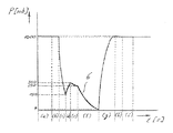
滅菌室1内の滅菌過程の時間的経過が図2に線図として示してあり、横座標は秒[s]単位の時間t、縦座標は滅菌室1内に存在するミリバール[mb]単位の圧力Pを示す。 The time course of the sterilization process in the sterilization chamber 1 is shown as a diagram in FIG. 2, the abscissa is the time t in seconds [s], and the ordinate is the millibar [mb] units present in the sterilization chamber 1. The pressure P is shown.
したがって図2に示す線図の曲線6は時間にわたる圧力推移を示す。 Accordingly, curve 6 of the diagram shown in FIG. 2 shows the pressure transition over time.
第1操作ステップ(a)では1群として用意された容器3が滅菌室1に運び込まれ、これは大気圧(1000mb)で行われる。次の操作ステップ(b)において滅菌室1は次にハーメチックに閉鎖される。閉鎖時間には約0.7秒が必要である。
In the first operation step (a), the
他の操作ステップ(c)の間、滅菌室1は400mb以下の圧力、主に約150mbに、つまり次に流入する水蒸気と過酸化水素蒸気との蒸気混合物が容器3の表面で凝縮し得るのを可能とする圧力に減圧される。予備減圧には約0.8秒が必要である。
During the other operation step (c), the sterilization chamber 1 is at a pressure of 400 mb or less, mainly about 150 mb, i.e. the vapor mixture of the next incoming steam and hydrogen peroxide vapor can condense on the surface of the
予備減圧された滅菌室1に蒸気混合物を入れるために操作ステップ(d)によれば約0.6秒が予定されている。引き続く操作ステップ(e)による凝縮は、選択された境界条件に応じて、約0.8秒続く。この時間内にすでに説明した過酸化水素の「活性化」が起き、これがきわめて迅速かつ根本的な滅菌がもたらされる。滅菌室内の圧力は蒸気混合物を入れる間、図2から明らかとなるように再び僅かに上昇する。 According to operation step (d), about 0.6 seconds is scheduled for putting the steam mixture into the pre-depressurized sterilization chamber 1. Condensation by the subsequent operating step (e) lasts about 0.8 seconds, depending on the boundary conditions selected. Within this time, the “activation” of hydrogen peroxide already described takes place, which leads to a very rapid and radical sterilization. The pressure in the sterilization chamber rises slightly again during the introduction of the steam mixture, as is evident from FIG.
いまや他の操作ステップ(f)において滅菌済み容器4から凝縮液が除去されねばならず、これは水および過酸化水素の実際の沸点より下の圧力に滅菌室1を減圧することによって行われる。操作ステップ(f)の最終圧力は4mbよりも多少下でなければならないことが判明した。これは滅菌過程のなかで最も時間のかかる段階であり、約3.4秒続く。
Now in another operating step (f), the condensate must be removed from the sterilized
凝縮液の排出後、滅菌室1は無菌ガス、例えば無菌空気または無菌窒素が0.5秒以内に急激に注入される。これは操作ステップ(g)の間に行われ、その後、機械設備の外側に存在する大気圧より約0.3mb上の圧力が達成される。最後に他の操作ステップ(h)、(i)において滅菌室1を開口し、滅菌済み容器4を開放し、開口した滅菌室1から輸送ベルト5に引き渡すことができる。
After the condensate is discharged, the sterilization chamber 1 is rapidly injected with aseptic gas, for example, aseptic air or aseptic nitrogen within 0.5 seconds. This takes place during the operating step (g), after which a pressure of about 0.3 mb above the atmospheric pressure present outside the mechanical installation is achieved. Finally, in the other operation steps (h) and (i), the sterilization chamber 1 can be opened, the sterilized
滅菌室1の積込み積出しを含む滅菌過程の総時間は約10.8秒である。 The total time of the sterilization process including loading and unloading of the sterilization chamber 1 is about 10.8 seconds.
滅菌室1に付属した機能要素の協働が図3に概略示してあり、これらの機能要素によって容器3が滅菌される。
The cooperation of the functional elements attached to the sterilization chamber 1 is shown schematically in FIG. 3, and the
ここで周期的に作動する機械設備では操作ステップ(c)、(f)が時間的にずれて起き、それゆえに両方の操作ステップ用に共通する吸排ユニット7を利用することができる。吸排ユニット7はベーンポンプ8とルーツポンプ9とからなる。
Here, in mechanical equipment that operates periodically, the operation steps (c) and (f) occur with a time lag, and therefore the intake /
操作ステップ(c)、(f)の間にきわめて異なる圧力条件が存在するので、制御可能な弁10を介して操作ステップ(c)のガス流はバイパス11によってルーツポンプ9の脇を通すことができ、このルーツポンプ9はいわば圧力の点で短絡することができる。これにより予備減圧段階(c)はベーンポンプ8のみによって処理される。
Since very different pressure conditions exist between the operating steps (c) and (f), the gas flow of the operating step (c) can be passed by the bypass 11 by the bypass 11 via the controllable valve 10. The Roots pump 9 can be short-circuited in terms of pressure. Thereby, the preliminary decompression stage (c) is processed only by the
付加的にガス緩衝器12が設けられ、制御可能な弁13を介してこのガス緩衝器を開くことができる場合、段階(c)の始めにガス緩衝器は注入することができ、これにより大量のガスが滅菌室1からこの予備減圧された容積内に急激に流れ、ベーンポンプ8によって移送する必要はない。この場合ベーンポンプ8は小型に設計できよう。充填されたガス緩衝器12は次に操作ステップ(a)、(b)、(g)、(h)、(i)の間、つまり本来ポンプ出力が要求されない段階に、再び減圧することができよう。
If a gas buffer 12 is additionally provided and can be opened via a controllable valve 13, the gas buffer can be injected at the beginning of step (c), thereby increasing the volume. Gas from the sterilization chamber 1 rapidly flows into the pre-depressurized volume and need not be transferred by the
操作ステップ(d)の間に必要とされる水蒸気と過酸化水素蒸気とからなる蒸気混合物は残りの段階の間に蒸発器14によって生成され、少なくとも100°に加熱された貯蔵容器15内に用意される。蒸気混合物の滅菌室1への流入はやはり加熱された複数の弁16を短時間開くことによって行われる。弁16の数は蒸気混合物の滅菌室1への均一な流入をもたらすものでなければならない。滅菌室1にノズル17が設けられており、これらのノズルを通して蒸気混合物が滅菌室1に流入し、流入の好適な空間的分布と好適な流入速度とを保証する。
The vapor mixture consisting of water vapor and hydrogen peroxide vapor required during the operation step (d) is produced by the evaporator 14 during the remaining stages and prepared in a
過酸化水素水溶液は矢印C方向で弁18を介して蒸発器14に供給される。それが必要な場合、弁19が蒸発器14の貯蔵容器15からの遮断を可能とする。他の弁20は管路21を介して貯蔵容器15の減圧を可能とする。したがって運転開始時に貯蔵容器15から空気を除去することができる。さらに、必要なら、貯蔵容器15内で周期的圧力低下を行うこともできる。これが必要となり得るのは、蒸気混合物の滅菌室1への流入後に貯蔵容器15内に過度に高い残留圧力が残る場合である。
The aqueous hydrogen peroxide solution is supplied to the evaporator 14 through the
比較的大きな設備の場合、貯蔵容器15に複数の蒸発器14が供給すると有意義であることがある。この貯蔵容器15はプロセスの制御と正常な機能の監視とのために温度センサ25および圧力センサ26を有する。
In the case of a relatively large facility, it may be meaningful to supply a plurality of evaporators 14 to the
操作ステップ(f)の間に凝縮液が残留物なしに除去されることは圧力センサ22によって監視される。約3.8mbの限界圧力を下まわると吸排弁23が閉じられ、注入弁24を介して無菌ガスは外部圧力に達するまで滅菌室1に注入される。その後にはじめて滅菌室1は開口できる。滅菌室1内で注入ガスを均一に分配させかつ不都合な流れ条件を防止するために複数の注入弁24が設けられている。同じ理由から吸排弁23も2つである。
It is monitored by the
操作ステップ(g)の間、注入のために約0.5秒以内に約130標準リットルのガス量が必要とされる。標準リットルのこの数は滅菌室1の容積に一致している。このようなガス流は過度に多く量定されるであろうので注入中に細菌濾過器に通すことができない。 During operation step (g), a gas volume of about 130 standard liters is required for injection within about 0.5 seconds. This number of standard liters corresponds to the volume of the sterilization chamber 1. Such a gas stream will be oversized and cannot be passed through a bacterial filter during injection.
この理由から、他の貯蔵容器27が設けられており、この貯蔵容器は残りのプロセス段階の間連続的に圧縮(gespannt)空気または圧縮窒素でもって細菌濾過器28および遮断弁29を介して無菌ガスが充填される。このため、好適なガスが矢印D方向で弁31を介して細菌濾過器28に供給される。
For this reason, another
急激な注入のゆえに、滅菌室1内に発生する圧力は事実上制御できない。しかしここでの場合のように容積比が既知である場合、滅菌室1内に発生する圧力は、注入前に貯蔵容器27内にまったく特定の圧力が生成されることによって精確に確定することができる。
Due to the rapid injection, the pressure generated in the sterilization chamber 1 is virtually uncontrollable. However, if the volume ratio is known, as in this case, the pressure generated in the sterilization chamber 1 can be accurately determined by generating a very specific pressure in the
この圧力は、圧力均衡後、貯蔵容器27内で予想される最終圧力を決定する。このため、ごく精密に作動する圧力センサ30が設けられている。
This pressure determines the expected final pressure in the
滅菌室1内の圧力は滅菌室1を開口する前に機械設備の外部圧力にごく精確に一致しなければならず、また圧力差によって発生する有害な流れが外部から滅菌室1の内部に達することのないように約0.3mbの僅かなゲージ圧を有しなければならない。機械ホールから機械設備領域に有菌空気が流入することはいずれにしても避けねばならない。 Before opening the sterilization chamber 1, the pressure in the sterilization chamber 1 must match the external pressure of the machine equipment very precisely, and harmful flow generated by the pressure difference reaches the inside of the sterilization chamber 1 from the outside. It must have a slight gauge pressure of about 0.3 mb. In any case, microbial air must be avoided from flowing into the machine equipment area from the machine hall.
無菌ガス用貯蔵容器27の容積は一方で場所が節約されるように極力小さくなければならないであろう。しかし他方で所要の圧力は単に、外部圧力のレベルへの注入精度が損なわれないような高さでなければならないであろう。良好な妥協点は1.5〜2.5barである。それとともに貯蔵容器の容積は滅菌室1の容積の1.5倍〜2倍にほぼ一致する。前記配置の場合、管路から単純に取り出した脱油乾燥圧縮空気をこのため使用することができる。
On the one hand, the volume of the sterile
Claims (7)
(a)開口した滅菌室に1群の容器を運び入れるステップ、
(b)滅菌室を閉鎖するステップ、
(c)滅菌室を500mb以下の圧力に予備減圧するステップ、
(d)水蒸気と過酸化水素蒸気とを含む蒸気混合物を滅菌室に供給するステップ、
(e)蒸気混合物を容器の表面で滅菌と同時に凝縮させるステップ、
(f)凝縮液の両方の成分が蒸発する圧力に滅菌室を減圧することによって、生成した凝縮液を除去するステップ、
(g)滅菌室に無菌ガスを注入するステップ、
(h)滅菌室を開口するステップ、
(i)1群の容器を滅菌室から取り出すステップ、を含み、
前述のステップ(e)が0.8秒内に行われることを特徴とする方法。 In a method for sterilizing a group of containers in a sterilized chamber capable of decompression,
(A) carrying a group of containers into an open sterilization chamber;
(B) closing the sterilization chamber;
(C) pre-depressurizing the sterilization chamber to a pressure of 500 mb or less;
(D) supplying a vapor mixture comprising water vapor and hydrogen peroxide vapor to the sterilization chamber;
(E) condensing the vapor mixture on the surface of the container simultaneously with sterilization;
(F) removing the produced condensate by depressurizing the sterilization chamber to a pressure at which both components of the condensate evaporate;
(G) injecting sterile gas into the sterilization chamber;
(H) opening the sterilization chamber;
(I) removing a group of containers from the sterilization chamber;
A method characterized in that said step (e) is performed within 0.8 seconds .
(a)開口した滅菌室に1群の容器を運び入れるステップ、
(b)滅菌室を閉鎖するステップ、
(c)滅菌室を500mb以下の圧力に予備減圧するステップ、
(d)水蒸気と過酸化水素蒸気とを含む蒸気混合物を滅菌室に供給するステップ、
(e)蒸気混合物を容器の表面で滅菌と同時に凝縮させるステップ、
(f)凝縮液の両方の成分が蒸発する圧力に滅菌室を減圧することによって、生成した凝縮液を除去するステップ、
(g)滅菌室に無菌ガスを注入するステップ、
(h)滅菌室を開口するステップ、
(i)1群の容器を滅菌室から取り出すステップ、を含み、
横長の滅菌室(1)に複数のノズル(17)が並べて設けられており、これらのノズル(17)が流入の空間的分布と流入速度とを保証するように、これらのノズル(17)を通して、それぞれに設けられた弁(16)を開くことによって蒸気混合物を滅菌室(1)に同時に流入させ、その際に、複数の一群の容器(3)が滅菌室(1)内にあることを特徴とする方法。 In a method for sterilizing a group of containers in a sterilized chamber capable of decompression,
(A) carrying a group of containers into an open sterilization chamber;
(B) closing the sterilization chamber;
(C) pre-depressurizing the sterilization chamber to a pressure of 500 mb or less;
(D) supplying a vapor mixture comprising water vapor and hydrogen peroxide vapor to the sterilization chamber;
(E) condensing the vapor mixture on the surface of the container simultaneously with sterilization;
(F) removing the produced condensate by depressurizing the sterilization chamber to a pressure at which both components of the condensate evaporate;
(G) injecting sterile gas into the sterilization chamber;
(H) opening the sterilization chamber;
(I) removing a group of containers from the sterilization chamber;
A plurality of nozzles (17) are provided side by side in the horizontally long sterilization chamber (1) , and these nozzles (17) pass through these nozzles (17) so as to ensure the spatial distribution of the inflow and the inflow speed. , allowed to flow simultaneously vapor mixture into the sterilization chamber (1) by opening the valve (16) provided in each of the case, that multiple group of containers (3) is in the sterilization chamber (1) in Feature method.
Applications Claiming Priority (2)
| Application Number | Priority Date | Filing Date | Title |
|---|---|---|---|
| DE10114758.9 | 2001-03-20 | ||
| DE2001114758 DE10114758B4 (en) | 2001-03-20 | 2001-03-20 | Method for sterilizing containers |
Related Parent Applications (1)
| Application Number | Title | Priority Date | Filing Date |
|---|---|---|---|
| JP2002573058A Division JP4162208B2 (en) | 2001-03-20 | 2002-03-02 | How to sterilize containers |
Publications (2)
| Publication Number | Publication Date |
|---|---|
| JP2008133054A JP2008133054A (en) | 2008-06-12 |
| JP4914971B2 true JP4914971B2 (en) | 2012-04-11 |
Family
ID=7679052
Family Applications (2)
| Application Number | Title | Priority Date | Filing Date |
|---|---|---|---|
| JP2002573058A Expired - Fee Related JP4162208B2 (en) | 2001-03-20 | 2002-03-02 | How to sterilize containers |
| JP2007318390A Expired - Fee Related JP4914971B2 (en) | 2001-03-20 | 2007-12-10 | How to sterilize containers |
Family Applications Before (1)
| Application Number | Title | Priority Date | Filing Date |
|---|---|---|---|
| JP2002573058A Expired - Fee Related JP4162208B2 (en) | 2001-03-20 | 2002-03-02 | How to sterilize containers |
Country Status (4)
| Country | Link |
|---|---|
| JP (2) | JP4162208B2 (en) |
| CN (1) | CN100408105C (en) |
| DE (1) | DE10114758B4 (en) |
| WO (1) | WO2002074351A1 (en) |
Families Citing this family (12)
| Publication number | Priority date | Publication date | Assignee | Title |
|---|---|---|---|---|
| EP1454639A1 (en) * | 2003-02-27 | 2004-09-08 | Rüdiger Haaga GmbH | Sterilisation process in a packaging transport system |
| FR2887526B1 (en) * | 2005-06-24 | 2007-09-07 | Sidel Sas | PROCESS FOR STERILIZING PREFORMS AND SYSTEM PRODUCING STERILE BOTTLES THEREFROM |
| DE102005035528A1 (en) * | 2005-07-26 | 2007-02-01 | Heim Medizintechnik Gmbh | Steam sterilizable blood separation device |
| DE102008015675A1 (en) | 2008-03-25 | 2009-10-01 | Khs Ag | Container handling machine |
| JP5332938B2 (en) * | 2009-06-22 | 2013-11-06 | 富士電機株式会社 | Electron beam irradiation type aseptic vacuum filling method and apparatus |
| DE102011054827A1 (en) * | 2011-10-26 | 2013-05-02 | Aesculap Ag | Medical sterile container and method for determining the sterilization status of a medical sterile container |
| DE102012019937A1 (en) | 2012-10-11 | 2014-04-17 | Fresenius Medical Care Deutschland Gmbh | sterilization procedures |
| US9302021B2 (en) * | 2013-08-30 | 2016-04-05 | American Sterilizer Company | Method of performing sterilization cycle |
| DE102014118776A1 (en) | 2014-12-16 | 2016-06-16 | Sig Technology Ag | Method and device for sterilizing containers |
| KR101825786B1 (en) | 2015-07-21 | 2018-02-07 | 씨제이제일제당 (주) | A sterilizer comprising reinforcement ribs |
| DE102015121322A1 (en) | 2015-12-08 | 2017-06-08 | Aesculap Ag | Medical recirculation lock, medical instrument and medical sterilization container |
| CN110960711B (en) * | 2019-12-31 | 2021-04-23 | 河南先途智能科技有限公司 | Plasma disinfection cabinet |
Family Cites Families (12)
| Publication number | Priority date | Publication date | Assignee | Title |
|---|---|---|---|---|
| SE423488C (en) * | 1977-10-17 | 1984-06-05 | Electrolux Ab | SET AND DEVICE FOR STERILIZATION WITH FORMALINE |
| SE423313B (en) * | 1977-10-17 | 1982-05-03 | Electrolux Ab | SET AND DEVICE FOR STERILIZATION WITH FORMALINE |
| US4512951A (en) * | 1980-12-30 | 1985-04-23 | American Sterilizer Company | Hydrogen peroxide liquid film sterilization method |
| JPS5969077A (en) * | 1982-10-12 | 1984-04-19 | アメリカン・ステリライザ−・コムパニ− | Sterilization by hydrogen peroxide liquid film |
| JPH01126906A (en) * | 1987-11-11 | 1989-05-19 | Nippon Health Supply:Kk | Insole |
| US4952370A (en) * | 1988-05-06 | 1990-08-28 | American Sterilizer Company | Hydrogen peroxide sterilization method |
| US4992247A (en) * | 1989-05-11 | 1991-02-12 | Elopak Systems, A.G. | Container sterilization system |
| US6325972B1 (en) * | 1998-12-30 | 2001-12-04 | Ethicon, Inc. | Apparatus and process for concentrating a liquid sterilant and sterilizing articles therewith |
| SE507994C2 (en) * | 1996-10-14 | 1998-08-10 | Tetra Laval Holdings & Finance | Ways of sterilizing packaging material |
| JPH10119934A (en) * | 1996-10-23 | 1998-05-12 | Shikoku Kakoki Co Ltd | Container sterilizing device, and sterilization of container packaging material |
| DE19806520A1 (en) * | 1998-02-17 | 1999-08-19 | Ruediger Haaga Gmbh | Process for sterilization, filling and sealing of product container using low pressure plasma as sterilizing agent |
| DE10044117A1 (en) * | 2000-09-07 | 2002-03-21 | Ruediger Haaga Gmbh | Process for sterilizing objects |
-
2001
- 2001-03-20 DE DE2001114758 patent/DE10114758B4/en not_active Expired - Fee Related
-
2002
- 2002-03-02 WO PCT/EP2002/002268 patent/WO2002074351A1/en active Application Filing
- 2002-03-02 CN CNB028068947A patent/CN100408105C/en not_active Expired - Fee Related
- 2002-03-02 JP JP2002573058A patent/JP4162208B2/en not_active Expired - Fee Related
-
2007
- 2007-12-10 JP JP2007318390A patent/JP4914971B2/en not_active Expired - Fee Related
Also Published As
| Publication number | Publication date |
|---|---|
| CN100408105C (en) | 2008-08-06 |
| DE10114758B4 (en) | 2013-01-31 |
| JP4162208B2 (en) | 2008-10-08 |
| WO2002074351A1 (en) | 2002-09-26 |
| JP2008133054A (en) | 2008-06-12 |
| JP2004528886A (en) | 2004-09-24 |
| DE10114758A1 (en) | 2002-09-26 |
| CN1498119A (en) | 2004-05-19 |
Similar Documents
| Publication | Publication Date | Title |
|---|---|---|
| JP4914971B2 (en) | How to sterilize containers | |
| US5749159A (en) | Method for precision cleaning and drying surfaces | |
| US6818178B2 (en) | Method for high vacuum sterilization of closures | |
| US20120060868A1 (en) | Microscale fluid delivery system | |
| US20130302207A1 (en) | Sterilization with in-line concentrating and injection of hydrogen peroxide | |
| BRPI0616681A2 (en) | system and method for treating wood materials | |
| JP4447013B2 (en) | Apparatus and method for humidifying a sterilization chamber | |
| CN101399182A (en) | Substrate treating apparatus and substrate treating method | |
| EP2139527B1 (en) | Quantitative liquid injection device of plasma sterilizer | |
| KR102334296B1 (en) | Systems and methods for controlling humidity | |
| EP0880972B1 (en) | Apparatus and method of sterilization | |
| KR102059995B1 (en) | Sterilization method using low-temperature sterilizer | |
| JPH09505228A (en) | Sterilization and drying method and device | |
| US20240082443A1 (en) | Process and device for sterilizing gas filtration means, in particular blowing air | |
| JP2004508104A (en) | How to sterilize goods | |
| JP2018011740A (en) | Steam sterilization device | |
| KR101846251B1 (en) | Method Using Low Temperature Sterilizer Having Chamber of Which Volume Is Variable | |
| JP4660084B2 (en) | Decontamination method and continuous aseptic apparatus | |
| JPH05131019A (en) | Method and device for sterilization and desinfection | |
| JP2018011739A (en) | Steam sterilization device | |
| JP2002126049A (en) | Method of driving control for steam sterilizer | |
| JP4900582B2 (en) | Method and apparatus for heat sterilization of solid matter | |
| JP2007185275A (en) | Residual gas removal method in gas sterilization | |
| JPH0515575A (en) | Sterilization of hydrogen peroxide gas supply device | |
| JP2016083089A (en) | Hydrogen peroxide gas sterilization apparatus |
Legal Events
| Date | Code | Title | Description |
|---|---|---|---|
| A131 | Notification of reasons for refusal |
Free format text: JAPANESE INTERMEDIATE CODE: A131 Effective date: 20100824 |
|
| A601 | Written request for extension of time |
Free format text: JAPANESE INTERMEDIATE CODE: A601 Effective date: 20101013 |
|
| A602 | Written permission of extension of time |
Free format text: JAPANESE INTERMEDIATE CODE: A602 Effective date: 20101018 |
|
| A601 | Written request for extension of time |
Free format text: JAPANESE INTERMEDIATE CODE: A601 Effective date: 20101104 |
|
| A602 | Written permission of extension of time |
Free format text: JAPANESE INTERMEDIATE CODE: A602 Effective date: 20101109 |
|
| A601 | Written request for extension of time |
Free format text: JAPANESE INTERMEDIATE CODE: A601 Effective date: 20101115 |
|
| A602 | Written permission of extension of time |
Free format text: JAPANESE INTERMEDIATE CODE: A602 Effective date: 20101118 |
|
| A521 | Written amendment |
Free format text: JAPANESE INTERMEDIATE CODE: A523 Effective date: 20101216 |
|
| A02 | Decision of refusal |
Free format text: JAPANESE INTERMEDIATE CODE: A02 Effective date: 20110712 |
|
| A521 | Written amendment |
Free format text: JAPANESE INTERMEDIATE CODE: A523 Effective date: 20111107 |
|
| A911 | Transfer of reconsideration by examiner before appeal (zenchi) |
Free format text: JAPANESE INTERMEDIATE CODE: A911 Effective date: 20111114 |
|
| TRDD | Decision of grant or rejection written | ||
| A01 | Written decision to grant a patent or to grant a registration (utility model) |
Free format text: JAPANESE INTERMEDIATE CODE: A01 Effective date: 20111213 |
|
| A01 | Written decision to grant a patent or to grant a registration (utility model) |
Free format text: JAPANESE INTERMEDIATE CODE: A01 |
|
| A61 | First payment of annual fees (during grant procedure) |
Free format text: JAPANESE INTERMEDIATE CODE: A61 Effective date: 20111216 |
|
| FPAY | Renewal fee payment (event date is renewal date of database) |
Free format text: PAYMENT UNTIL: 20150203 Year of fee payment: 3 |
|
| R150 | Certificate of patent or registration of utility model |
Free format text: JAPANESE INTERMEDIATE CODE: R150 |
|
| LAPS | Cancellation because of no payment of annual fees |