JP4913402B2 - Method for producing labeled pouch - Google Patents
Method for producing labeled pouch Download PDFInfo
- Publication number
- JP4913402B2 JP4913402B2 JP2005367370A JP2005367370A JP4913402B2 JP 4913402 B2 JP4913402 B2 JP 4913402B2 JP 2005367370 A JP2005367370 A JP 2005367370A JP 2005367370 A JP2005367370 A JP 2005367370A JP 4913402 B2 JP4913402 B2 JP 4913402B2
- Authority
- JP
- Japan
- Prior art keywords
- pouch
- label
- forming region
- back surface
- film
- Prior art date
- Legal status (The legal status is an assumption and is not a legal conclusion. Google has not performed a legal analysis and makes no representation as to the accuracy of the status listed.)
- Expired - Fee Related
Links
- 238000004519 manufacturing process Methods 0.000 title claims description 20
- 238000000034 method Methods 0.000 claims description 41
- 239000004744 fabric Substances 0.000 claims description 32
- 238000007789 sealing Methods 0.000 claims description 13
- 238000013461 design Methods 0.000 description 15
- 239000010410 layer Substances 0.000 description 14
- 230000015572 biosynthetic process Effects 0.000 description 9
- 235000013305 food Nutrition 0.000 description 8
- 239000000463 material Substances 0.000 description 8
- -1 polyethylene Polymers 0.000 description 8
- 230000004888 barrier function Effects 0.000 description 6
- 239000002344 surface layer Substances 0.000 description 6
- 239000004677 Nylon Substances 0.000 description 4
- VYPSYNLAJGMNEJ-UHFFFAOYSA-N Silicium dioxide Chemical compound O=[Si]=O VYPSYNLAJGMNEJ-UHFFFAOYSA-N 0.000 description 4
- 238000005520 cutting process Methods 0.000 description 4
- 229920001778 nylon Polymers 0.000 description 4
- 239000000565 sealant Substances 0.000 description 4
- 239000004743 Polypropylene Substances 0.000 description 3
- 235000013361 beverage Nutrition 0.000 description 3
- 238000002372 labelling Methods 0.000 description 3
- 229920002647 polyamide Polymers 0.000 description 3
- 229920006267 polyester film Polymers 0.000 description 3
- 239000005020 polyethylene terephthalate Substances 0.000 description 3
- 229920000139 polyethylene terephthalate Polymers 0.000 description 3
- 229920001155 polypropylene Polymers 0.000 description 3
- 229920003002 synthetic resin Polymers 0.000 description 3
- 239000000057 synthetic resin Substances 0.000 description 3
- 238000007740 vapor deposition Methods 0.000 description 3
- 239000004952 Polyamide Substances 0.000 description 2
- 239000004820 Pressure-sensitive adhesive Substances 0.000 description 2
- 239000000853 adhesive Substances 0.000 description 2
- 230000001070 adhesive effect Effects 0.000 description 2
- 229910052782 aluminium Inorganic materials 0.000 description 2
- XAGFODPZIPBFFR-UHFFFAOYSA-N aluminium Chemical compound [Al] XAGFODPZIPBFFR-UHFFFAOYSA-N 0.000 description 2
- 238000005452 bending Methods 0.000 description 2
- 229920000092 linear low density polyethylene Polymers 0.000 description 2
- 239000004707 linear low-density polyethylene Substances 0.000 description 2
- 229910052751 metal Inorganic materials 0.000 description 2
- 239000002184 metal Substances 0.000 description 2
- 238000012986 modification Methods 0.000 description 2
- 230000004048 modification Effects 0.000 description 2
- 238000012856 packing Methods 0.000 description 2
- 239000000377 silicon dioxide Substances 0.000 description 2
- 239000000126 substance Substances 0.000 description 2
- 229920000219 Ethylene vinyl alcohol Polymers 0.000 description 1
- 239000004698 Polyethylene Substances 0.000 description 1
- 229920001328 Polyvinylidene chloride Polymers 0.000 description 1
- 235000021438 curry Nutrition 0.000 description 1
- 235000011850 desserts Nutrition 0.000 description 1
- 239000003599 detergent Substances 0.000 description 1
- 239000005038 ethylene vinyl acetate Substances 0.000 description 1
- 239000011888 foil Substances 0.000 description 1
- 230000004927 fusion Effects 0.000 description 1
- 229920001903 high density polyethylene Polymers 0.000 description 1
- 239000004700 high-density polyethylene Substances 0.000 description 1
- 235000015243 ice cream Nutrition 0.000 description 1
- 238000010030 laminating Methods 0.000 description 1
- 239000004745 nonwoven fabric Substances 0.000 description 1
- TWNQGVIAIRXVLR-UHFFFAOYSA-N oxo(oxoalumanyloxy)alumane Chemical compound O=[Al]O[Al]=O TWNQGVIAIRXVLR-UHFFFAOYSA-N 0.000 description 1
- 229920000573 polyethylene Polymers 0.000 description 1
- 239000005033 polyvinylidene chloride Substances 0.000 description 1
- 239000000843 powder Substances 0.000 description 1
- 235000013324 preserved food Nutrition 0.000 description 1
- 238000003825 pressing Methods 0.000 description 1
- 229920005653 propylene-ethylene copolymer Polymers 0.000 description 1
- 238000012797 qualification Methods 0.000 description 1
- 229920005989 resin Polymers 0.000 description 1
- 239000011347 resin Substances 0.000 description 1
- 238000003860 storage Methods 0.000 description 1
Images


Landscapes
- Bag Frames (AREA)
- Making Paper Articles (AREA)
Description
本発明は、内側へ折り畳まれた側面ガセット部にラベルが貼付されたラベル付きパウチの製造方法に関する。 The present invention relates to the production how labeled pouch label affixed to the side gusset portions which are folded inwardly.
従来、飲料、ゼリー状食品、レトルト食品などの充填物を封入する容器として、可撓性フィルムからなり、表面部及び裏面部と、該表裏面部の間に内側に折り込まれた側面ガセット部とを有する側面ガセット付きパウチが知られている。
かかるパウチは、内部に充填物を封入した状態で、或いは、パウチの上部に充填物注出用のスパウトを取付け且つ内部に充填物を封入したスパウト付きパウチ容器の態様などで利用されている。
Conventionally, as a container for filling a filling such as beverages, jelly-like foods, retort foods, etc., it is made of a flexible film, and includes a front surface portion and a back surface portion, and a side gusset portion folded inward between the front and back surface portions. A pouch with side gussets is known.
Such a pouch is used in a state in which a filling is enclosed inside, or in the form of a pouch container with a spout in which a spout for filling filling is attached to the top of the pouch and the filling is enclosed inside.
かかる側面ガセット部を有するパウチを機械的に製袋する際には、下記の手順からなる。
図10に示すように、パウチの表裏面部を形成する長尺状の表面フィルム原反120及び裏面フィルム原反130(尚、表裏面フィルム原反120,130には、製袋される個々のパウチに対応して、同一の意匠表示が長手方向に所定間隔をあけて印刷されている)の両側間に、側面ガセット部150を形成する長尺状の側面フィルム原反を折りながら挟み込む。これを送りながら縦シール装置210で、表裏面フィルム原反120,130の上下から加熱して、表裏面フィルム原反120,130の側端部の内面と各側面フィルム原反150の側端部の内面を所定幅熱シールする。続いて、横シール装置220で下端部を熱シールし、これをカッター230で横方向に切断することにより、1つの意匠表示が表裏面部に表されたパウチ100が得られる。これを連続的に行うことにより、多数のパウチ100を多数製造できる。その後、上端開口部から充填物を入れて該開口部を熱シールすることにより、充填物を封入したパウチを製造できる。また、開口部にスパウトを挟み込んだ状態でこれを熱シールし、スパウトから充填物を入れ、スパウトのキャップを取り付けることにより、充填済みのスパウト付きパウチ容器を製造できる。
When a pouch having such a side gusset portion is mechanically made, the procedure is as follows.
As shown in FIG. 10, a long surface film
ところで、従来より、飲料容器、食品容器などの各種の商品に、くじや景品等の応募券などとして使用されるキャンペーンラベルなどの各種ラベルが貼付されている。
かかるラベルを、上記パウチの側面ガセット部に貼付する場合、充填物を封入する前に於いては、折り込まれた側面ガセット部を展開しなければラベルを貼付できず、ラベル貼付作業が困難である。一方、充填後に於いては、パウチ全体が膨むことで側面ガセット部は展開するが、側面ガセット部にラベルを押しつけても側面ガセット部が内側へ湾曲するので、十分な押圧力を以てラベルを貼付できない。
By the way, conventionally, various labels such as campaign labels used as application tickets for lotteries and giveaways are affixed to various products such as beverage containers and food containers.
When affixing such a label to the side gusset part of the pouch, the label cannot be attached unless the folded side gusset part is unfolded before the filling is sealed, and the label affixing operation is difficult. . On the other hand, after filling, the side gusset part expands as the entire pouch swells, but even if the label is pressed against the side gusset part, the side gusset part curves inward, so the label is attached with sufficient pressing force. Can not.
このような点から、上記パウチの製造時、上記側面フィルム原反150の外面に、製袋される個々のパウチに1つのラベルが対応するように、所定間隔をあけてラベルを貼付し、この側面フィルム原反150を、表裏面フィルム原反120,130の間に折り込んで製袋することが考えられる。
しかしながら、上記製法では、表面フィルム原反120、裏面フィルム原反130、及び側面フィルム原反150は、別個独立した長尺状のフィルムからなるため、各フィルム原反の伸びなどに起因して、表裏面フィルム原反120,130と側面フィルム原反150とが、長手方向に位置ずれを生じる。
このように表裏面フィルム原反120,130と側面フィルム原反150は、製袋時に長手方向に位置ずれするので、表面フィルム原反120(又は裏面フィルム原反130)に印刷された意匠表示を基準にして、側面フィルム原反150のラベルが所定の位置とならず、表面部の意匠表示に対してラベル貼付位置のずれたパウチが多数製造されるという問題点がある。
From this point, when manufacturing the pouch, a label is affixed to the outer surface of the side film
However, in the above manufacturing method, the front film
Thus, since the front and back film
そこで、本発明は、表面部(又は裏面部)を基準にして、側面ガセット部の所定位置にラベルが貼付されたラベル付きパウチを量産できる製造方法を提供することを課題とする。 Accordingly, the present invention is to surface portion (or the back surface) as a reference, and to provide a manufacturing how that can mass-produced labeled pouch label in a predetermined position of the side gusset portions is affixed.
本発明は、1枚のフィルムから形成され、表面部及び裏面部と該表裏面部の間に折り込まれた側面ガセット部と表裏面部の上端部に取り付けられたスパウトとを有するパウチの製造方法であって、1枚の長尺状のフィルム原反の側面ガセット部形成領域を、該フィルム原反の表裏面部形成領域の間に折り込む折込工程、側面ガセット部形成領域の側端部と表裏面部形成領域の側端部とを熱シールする接着工程、製袋後に、表裏面部の上端部の開口にスパウトを挟み込み、スパウトと共に上端部を熱シールするスパウト取付工程、を有し、折込工程前又は折込工程中に、側面ガセット部形成領域の外面であって側面ガセット部形成領域の幅方向中心部に形成される折り目と前記側面ガセット部形成領域の熱シールされる側端部との間に、ラベルを貼付するラベル付きパウチの製造方法を提供する。 The present invention is a method for manufacturing a pouch that is formed of a single film and has a front surface portion and a back surface portion, a side gusset portion that is folded between the front and back surface portions, and a spout attached to the upper end portion of the front and back surfaces. Folding step of folding the side gusset portion forming region of one long film original fabric between the front and back surface forming regions of the film original fabric, side end portions and front and back surface forming regions of the side gusset portion forming region Adhesive process for heat-sealing the side end of the bag, and after bag making, a spout is sandwiched in the opening at the upper end of the front and back surfaces, and the upper end is heat-sealed together with the spout, before the folding process or the folding process during, between the side edge that will be heat-sealed folds before SL side surface gusset portion forming region and a outer surface of the side gusset portion forming region is formed in the widthwise center portion of the side gusset portion forming region, label To provide a method of manufacturing a label with a pouch to be attached.
上記ラベル付きパウチの製造方法によれば、フィルム原反の側面ガセット部形成領域を折り込む前又は折り込み中に、側面ガセット部形成領域の外面であって側面ガセット部形成領域の幅方向中心部に形成される折り目と前記側面ガセット部形成領域の熱シールされる側端部との間にラベルを貼付するので、ラベル貼付のために側面ガセット部を展開する必要はない。
そして、表裏面部形成領域と両側面ガセット部形成領域が1枚のフィルム原反からなるので、側面ガセット部形成領域を表裏面部形成領域の間に折り込む際に、表裏面部形成領域と側面ガセット部形成領域とが長手方向に位置ずれしない。
よって、表面部(又は裏面部)を基準にして、側面ガセット部の所定位置にラベルが貼付された同一のパウチを多数製造できる。
According to the method for manufacturing a labeled pouch, before or during folding of the side gusset portion forming region of the original film, the outer side surface of the side gusset portion forming region is formed at the center in the width direction of the side gusset portion forming region. since locating the label between the folds and the front SL side surface gusset portion side end portion is heat sealed Ru forming region to be, there is no need to deploy the side gussets for labeling.
And since the front and back surface forming area and the both side gusset forming area are made of a single film, when the side gusset forming area is folded between the front and back surface forming areas, the front and back surface forming area and the side gusset forming The region is not displaced in the longitudinal direction.
Therefore, a large number of the same pouches with labels attached to predetermined positions of the side face gusset portion can be manufactured with reference to the front surface portion (or back surface portion).
本発明のラベル付きパウチの製造方法は、表裏面部を基準にして、側面ガセット部の所定位置にラベルが貼付された同一のラベル付きパウチを多数製造できる。
また、上記製法は、側面ガセット部形成領域を表裏面部形成領域に折り込む前又は折り込み中に、側面ガセット部形成領域の外面の所定位置にラベルを貼付するだけなので、例えば既存のパウチ製袋機にラベル貼付装置を付加するだけで、側面ガセット部の所定位置にラベルが貼付された同一のラベル付きパウチを多数製造できる。
The method for manufacturing a labeled pouch according to the present invention can manufacture a large number of the same labeled pouches with labels attached to predetermined positions of the side face gusset portion with reference to the front and back surfaces.
In addition, since the above-described manufacturing method only attaches a label to a predetermined position on the outer surface of the side surface gusset portion forming region before or during folding the side surface gusset portion forming region into the front and back surface portion forming region, for example, to an existing pouch bag making machine. By simply adding a label attaching device, a large number of the same labeled pouches with labels attached to predetermined positions of the side gusset portion can be manufactured.
以下、本発明について、図面を参照しつつ具体的に説明する。
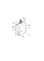
図1〜図3に於いて、1は、表面部2及び裏面部3と、該表裏面部2,3(以下、表面部と裏面部を合わせて表裏面部という場合がある)の間に折り込まれた両側面ガセット部5,5と、を有するラベル付きパウチを示し、側面ガセット部5の外面には、ラベル7が貼付されている。
このパウチ1の表裏面部2,3の上端部2aには、スパウト8が挟み込まれ、且つ熱シールすることで、該パウチ1はスパウト付きパウチ容器の態様とされている。
Hereinafter, the present invention will be specifically described with reference to the drawings.
1 to 3, 1 is folded between the
A
該パウチ1は、充填後、図1に示すように、表裏面部2,3の下方部が折り曲げられて載置用の底面が構成される自立型パウチである。
As shown in FIG. 1, the
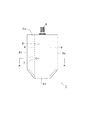
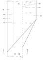
具体的には、パウチ1は、図3(a)に示すように、表面部2、裏面部3及び折り込まれた両側面ガセット部5,5の4面が、1枚の可撓性積層フィルムから形成されている。
表裏面部2,3は、下方両側が斜め状に切断された正面六角形状に形成されている。側面ガセット部5は、表裏面部2,3の下方傾斜に沿うように、下方両側が斜めに形成されている。
該両側面ガセット部5,5の両側端部5b,5bと表裏面部2,3の両側端部2b,3bが、長手方向に熱シールされ、表裏面部2,3の下端部2cが、幅方向に熱シールされ、表裏面部2,3の上端部2aが、スパウト8を挟み込んだ状態で幅方向に熱シールされることにより、内部に充填物を封入可能なパウチ1が構成されている。
1枚のフィルムからなる上記パウチ1は、該フィルムの一側端縁が一方の側面ガセット部5の一側端縁を構成し、フィルムの他側端縁が表面部2の一側端縁を構成している。
Specifically, as shown in FIG. 3A, the
The front and
Both
In the
折り込まれた両側面ガセット部5,5のうち、一方の側面ガセット部5には、1個のラベル7が貼付されている。尚、ラベル7は、側面ガセット部5に2個以上貼付されていてもよいし、又、両側面ガセット部5,5の双方に貼付されていてもよい。
このラベル7は、側面ガセット部5の側端部5b(熱シール部)と中心部の折り目の間に貼付されている。
ラベル7は、ラベル基材の裏面に粘着剤又は接着剤が設けられ、側面ガセット部5の外面に貼付可能なもので、好ましくは、手で剥離可能で且つ再貼付可能な感圧型粘着剤を用いるのがよい。
ラベル7の種類は特に限定されず、例えば、ラベル基材に、スピードくじ、景品応募券、懸賞応募用IDなどの懸賞応募資格に関する表示が印刷された所謂キャンペーンラベルが挙げられる。また、このようなキャンペーンラベル以外に、例えば、キャラクターバッチやキャラクターシールなどの葉状体からなるおまけが取出し可能に収納された収納ラベル、ICタグが具備されたICラベルなどの従来公知のラベル7を用いることもできる。
One
The
The
The type of the
パウチ1を構成する1枚のフィルムとしては、例えば、図3(b)に示すように、内面側から外面側に向かって順に、熱融着するためのシーラント層41、袋の強度(耐屈曲性、耐ピンホール性など)を保持するための基材層42、ガスバリア性や遮光性などを付与するためのバリア層43、表面摩擦や耐熱性などを付与するための外面層44がラミネート加工された4層構造の積層フィルムを例示できる。
シーラント層41は、熱融着可能な素材であれば特に限定されず、例えば、高密度ポリエチレン、直鎖状低密度ポリエチレンなどのポリエチレン、ポリプロピレン、エチレン−酢酸ビニル共重合体などを用いることができる。これらのうち熱融着性に優れる直鎖状低密度ポリエチレンフィルムを用いることが好ましい。基材層42は、比較的強度に優れるものであれば特に限定されず、ナイロンなどのポリアミド系フィルム、ポリエチレンテレフタレートなどのポリエステル系フィルム、ポリプロピレン、プロピレン−エチレン共重合体などのポリプロピレン系フィルムなどの合成樹脂製フィルム、合成紙など、又は2種以上の積層体などを用いることができる。これらのうち耐屈曲性に優れる6ナイロン、6,6ナイロンなどのポリアミド系フィルムを用いることが好ましい。バリア層43は、ガスバリア性を有するものであれば特に限定されず、アルミニウムなどの金属箔、シリカ蒸着フィルム、ポリ塩化ビニリデンやエチレン−ビニルアルコール共重合体などのガスバリア性を有する合成樹脂製フィルム、2種以上の積層体などを用いることができる。これらの中でアルミニウム、酸化アルミなどの金属蒸着フィルムやシリカ蒸着フィルムを用いることが好ましい。外面層44は、例えば、ポリエチレンテレフタレートなどのポリエステル系フィルム、ポリプロピレン、ナイロンなどのポリアミド系フィルムなど、又は2種以上の積層体などを用いることができ、更に、合成樹脂製フィルムの場合は延伸フィルムを用いることが好ましい。これらのうち熱融着時の耐熱性、寸法安定性などに優れるポリエチレンテレフタレートなどのポリエステル系フィルムを用いることが好ましい。
尚、積層フィルムは、上記層構成のものに限定されず、例えば、シーラント層41と外面層44の積層体や、更に、不織布、発泡樹脂シートなどの断熱層を、上記層構成に付加又は適宜代用することもできる。
As one film constituting the
The sealant layer 41 is not particularly limited as long as it is a heat-sealable material. For example, polyethylene such as high-density polyethylene and linear low-density polyethylene, polypropylene, ethylene-vinyl acetate copolymer, and the like can be used. . Of these, it is preferable to use a linear low-density polyethylene film having excellent heat-fusibility. The
The laminated film is not limited to the one having the above layer structure, and for example, a laminated body of the sealant layer 41 and the
尚、外面層44の内面又は外面には、商品名、絵柄などの意匠表示が印刷されており、この意匠表示を内面に印刷する場合には、外面層44は透明なものが用いられる。
意匠表示を印刷する部分は、特に限定されないが、この種パウチは、通常、表面部2又は/及び裏面部3に、意匠表示が印刷される。該意匠表示の内容は、特に限定されないが、側面ガセット部5のラベル7の貼付位置をユーザーに知らしめるため、図示したような矢印マークの他、「ここにラベルが貼付されています」などのユーザーに注意を喚起する貼付指示表示を表面部2又は/及び裏面部3に表すことが好ましい。この貼付指示表示が指し示す位置に対応して、ガセット部15にラベル7が貼付されており、これによりラベル7の貼付位置をユーザーに的確に判らせることができる。
尚、側面ガセット部5にも意匠表示が印刷されていてもよい。
In addition, a design display such as a trade name and a pattern is printed on the inner surface or the outer surface of the
Although the part which prints a design display is not specifically limited, As for this kind pouch, a design display is normally printed in the
A design display may also be printed on the
上記パウチは、例えば、次の製袋工程で機械的に製造することができる。
<前工程>
まず、1個のパウチ1(表裏面部2,3及び両側面ガセット部5,5)を形成できる幅の長尺状の1枚のフィルム原反10を準備する。
このフィルム原反10は、幅方向に1列のパウチ1を形成する場合に使用されるが、幅方向に2列のパウチ1を形成する場合には、上記フィルム原反10の2倍幅超のフィルム原反を準備し、又、幅方向にX列のパウチを形成する場合には、上記フィルム原反10のX倍幅超のフィルム原反を準備すればよい。以下、幅方向に1列のパウチ1を形成する場合を例にして説明する。
この長尺状のフィルム原反10の少なくとも表面部形成領域12の外面には、製袋される個々のパウチ1に対応して、同一の意匠表示(図では矢印マークのみを表す)が長手方向に所定間隔をあけて印刷されている。
該長尺状の1枚のフィルム原反10の側面ガセット部形成領域15の外面に、ラベル7を貼付するラベル貼付工程、該フィルム原反10の側面ガセット部形成領域15を、該フィルム原反10の表裏面部形成領域12,13の間に折り込む折込工程、側面ガセット部形成領域15の側端部と表裏面部形成領域12,13の側端部とを接着する接着工程、を経て、上記パウチ1が製造される。以下、工程毎に順次説明する。
The pouch can be mechanically manufactured in the following bag making process, for example.
<Pre-process>
First, a single long film original 10 having a width capable of forming one pouch 1 (front and
This film
On the outer surface of at least the surface
A label affixing step of attaching the
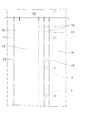
<折り目形成工程>
図4に示すように、ロール状に巻き取られた上記長尺状の1枚のフィルム原反10を引き出し、フィルム原反10の内面側(又は外面側でもよい)に折り目形成装置のローラを当てがい、幅方向に複数本の折り目16,17(一点鎖線で表している)を長手方向に直線状に形成する。折り目16を介して、フィルム原反10は、表面部2を形成する表面部形成領域12、一方の側面ガセット部5を形成する側面ガセット部形成領域15、裏面部3を形成する裏面部形成領域13、他方の側面ガセット部5を形成する側面ガセット部形成領域15に、それぞれ区画される。また、側面ガセット部形成領域15の中心部には、折り目17が形成される。
尚、製袋装置によっては、折り目形成工程を省略することもできる。
<Creasing process>
As shown in FIG. 4, the above-mentioned long film
Depending on the bag making apparatus, the crease forming step may be omitted.
<ラベル貼付工程>
上記フィルム原反10を引き出し、ラベル貼付装置によって、一方の側面ガセット部形成領域15の外面の所定位置にラベル7を貼付する。該ラベル7は、表面部形成領域12(又は裏面部形成領域13)に印刷された意匠表示或いは側面ガセット部形成領域15に印刷された意匠表示を基準にして、所定位置に貼付される。例えば、表面部形成領域12に、上記矢印マークなどの貼付指示表示が印刷されている場合、該貼付指示表示に対応する位置に、ラベル7が貼付される。かかるラベル7は、側面ガセット部形成領域15の長手方向に、所定間隔をあけて(製袋される個々のパウチ1に、ラベル7が貼付されるように間隔をあけて)、複数貼付される。このラベル7は、側面ガセット部形成領域15の所定位置に貼付されるため、側面ガセット部形成領域15に成分表示などの重要な意匠表示などが印刷されている場合であってもその意匠表示の上に重ねてラベル7が貼付されることを防止できる。
また、このラベル7は、側面ガセット部形成領域15と表裏面部形成領域12,13の境界線に形成された折り目16と、側面ガセット部形成領域15の幅方向中心部に形成された折り目17との間に貼付される。
尚、ラベル貼付工程は、上記折り目形成工程の前に行うこともできる。
<Labeling process>
The
The
In addition, a label sticking process can also be performed before the said crease formation process.
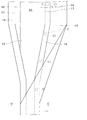
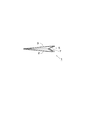
<折込工程>
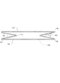
次に、図5に示すように、折り込み装置によって、上記フィルム原反10を、各折り目16,17に沿って折り曲げていく。すなわち、フィルム原反10の側面ガセット部形成領域15と表裏面部形成領域12,13の間の折り目16にて外側に山折りすると共に、側面ガセット部形成領域15の中心部の折り目17にて側面ガセット部形成領域15を内側に谷折りして、側面ガセット部形成領域15を表裏面部形成領域12.13の間に折り込む。
かかる折込工程を経たフィルム原反10は、図6に示すように、表裏面部形成領域12,13の間に、両側面ガセット部形成領域15,15が略V字状に折り込まれた状態となっている。
尚、上記ラベル貼付工程を折込工程中に行うことも可能である。例えば、側面ガセット部形成領域15を内側へ折り込みながら、この折り込みと同時に側面ガセット部形成領域15の所定位置にラベル7を貼付してもよい。もっとも、折込工程前にラベル貼付工程を行う方が、ラベル7を側面ガセット形成領域15に確実に貼付できるので好ましい。
<Folding process>
Next, as shown in FIG. 5, the
As shown in FIG. 6, the
In addition, it is also possible to perform the said label sticking process in a folding process. For example, the
<接着工程>
次に、縦シール装置によって、両側面ガセット部形成領域15,15の両側端部と表裏面部形成領域12,13の両側端部を、長手方向に所定幅熱シールすると共に、横シール装置によって、表裏面部形成領域12,13の下端部を幅方向に熱シールする。これにより、複数のパウチが長手方向に繋がったパウチ連続体が得られる。
<Adhesion process>
Next, the longitudinal sealing device heat seals both side ends of the side surface gusset
<切断工程>
そして、パウチ連続体から個々のパウチを得るべく、表裏面部形成領域12,13の下端部に形成された熱シール部のうち、余分な部分を切除しつつ幅方向に切断することにより、上面部の開口されたパウチが得られる。順次送られてくるパウチ連続体を切断することにより、開口パウチが量産される。
<Cutting process>
Then, in order to obtain individual pouches from the pouch continuum, the upper surface portion is cut in the width direction while cutting off excess portions of the heat seal portions formed at the lower end portions of the front and back
<スパウト取付工程>
最後に、該上端部が開口されたパウチの該開口部にスパウトを挟み込み、スパウトと共に上端部を熱シールすることにより、スパウトの付いた上記パウチ1が製造される。
<Spout mounting process>
Finally, the
上記ラベル付きパウチの製造方法は、フィルム原反10の側面ガセット部形成領域15を折り込む前に、側面ガセット部形成領域15の所定位置にラベル7を貼付するので、ラベル貼付のために側面ガセット部5を展開する必要がない。
さらに、表裏面部形成領域12,13と両側面ガセット部形成領域15,15が1枚のフィルム原反10からなるので、側面ガセット部形成領域15を、表裏面部形成領域12,13の間に折り込む際に、表裏面部形成領域12,13と側面ガセット部形成領域15とが長手方向に位置ずれしない。
従って、上記製造方法によれば、表面部2(又は裏面部3)の意匠表示を基準にして、側面ガセット部5の所定位置にラベル7が貼付された同一のラベル付きパウチ1を多数製造できる。
また、上記製造方法は、側面ガセット部形成領域15を折り込む前に、側面ガセット部形成領域15の外面の所定位置にラベル7を貼付すればよいため、ラベル貼付装置を具備する既存のパウチ製袋機、又は既存のパウチ製袋機にラベル貼付装置を付加するだけで、同一のラベル付きパウチ1を多数製造できる。
Since the
Furthermore, since the front and back
Therefore, according to the said manufacturing method, many
Moreover, since the manufacturing method should just affix the
尚、本発明は、上記で示した各実施形態に限られず、その他、変更、代用、置換、付加などすることができる。以下、主として上記各実施形態と異なる部分について説明し、同様の構成については用語及び図番を援用し、その説明を省略することがある。 The present invention is not limited to the above-described embodiments, and can be modified, substituted, replaced, added, and the like. Hereinafter, parts different from those of the above embodiments will be mainly described, and the same configuration may be referred to using terms and figure numbers, and the description thereof may be omitted.
本発明のラベル付きパウチ1は、上記のようにスパウト付きパウチ容器の態様で使用される他、スパウト8を取り付けず、充填物を封入する袋の態様で使用することもできる。
また、パウチ1に封入される充填物は、特に限定されず、ゼリー状食品、アイスクリームなどの冷菓、飲料、カレーなどの調理済み食品、乾物などの未調理食品、粉体などの食品の他、薬品などの医療関連品、洗剤などの化学製品、おもちゃ、工業製品の部品などの食品以外の各種商品が挙げられる。
The labeled
In addition, the filling material enclosed in the
さらに、上記では、側面ガセット部5が両側に形成されたパウチ1を例示しているが、図7に示すように、片側にのみ側面ガセット部5が形成されたパウチ1に本発明を適用することもできる。
また、上記では、表裏面部2,3及び側面ガセット部5からなるパウチ1を例示しているが、例えば、別個のフィルムを表裏面部2,3の下方に介在させ、且つこれらを熱シールすることにより、表裏面部2,3、側面ガセット部5及び底面部を有するパウチに本発明を適用することもできる。
尚、表裏面部2,3は、正面六角形状に形成されているものに限られず、正面矩形状でもよいし、或いは、正面四角形状、正面八角形状などに形成することも可能である。
Further, in the above, the
Moreover, in the above, although the
The front and
また、上記ラベル付きパウチ1の製造方法に於いて、折込工程の後、接着工程を行っているが、接着工程を、折込工程の前後に2回に分けて行うこともできる。
具体的には、上記と同様にして、前工程、折り目形成工程及びラベル貼付工程を経た後、下記の工程を行う。
<第1接着工程>
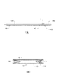
図8に示すように、折り目16,17を形成した1枚のフィルム原反10(尚、上記の通り、折り目形成工程が省略される場合には、折り目16,17のないフィルム原反10)の両側端部の内面を重ね合わせ、縦シール装置によって、長手方向に熱シールを行う。この接着により、1枚のフィルム原反10は、図9(a)に示すように、長尺状の筒状体に形成される。
Moreover, in the manufacturing method of the said labeled
Specifically, in the same manner as described above, after the pre-process, the crease forming process, and the label attaching process, the following process is performed.
<First bonding step>
As shown in FIG. 8, one sheet of
<折込工程>
次に、折り込み装置によって、上記筒状のフィルム原反10を、折り目16,17に沿って折り曲げる。折り込み方法は、上記と同様である。これにより、図9(b)に示すように、表裏面部形成領域12,13の間に、両側面ガセット部形成領域15,15が略V字状に折り込まれた筒状体が得られる。
<Folding process>
Next, the said cylindrical film
<第2接着工程>
次に、縦シール装置によって、上記実施形態と同様にして、側面ガセット部形成領域15の両側端部と表裏面部形成領域12,13の両側端部を、長手方向に所定幅熱シールすると共に、横シール装置によって、表裏面部形成領域12,13の下端部を幅方向に熱シールする。これにより、複数のパウチが長手方向に繋がったパウチ連続体が得られる。
以下、上記切断工程以降の工程を経て、側面ガセット部5の所定位置にラベル7が貼付された同一のラベル付きパウチ1が多数製造される。
<Second bonding step>
Next, in the same manner as in the above-described embodiment, the vertical sealing device heat-seal both side ends of the side surface gusset
Thereafter, through the steps after the cutting step, a number of the same labeled
さらに、上記接着工程を折込工程の前後に分けて行う変形例に係るパウチの製造方法に於いては、第1接着工程の前にラベル貼付工程を行うものであるが、これに代えて、第1接着工程と折込工程の間に、ラベル貼付工程を行うこともできる。つまり、1枚のフィルム原反10を第1接着工程で筒状体に形成した後、その筒状体の側面ガセット部形成領域15の所定位置に、ラベル7を貼付し、次に、側面ガセット部形成領域15を、表裏面部形成領域12,13の間に折り込むという手順に変更することもできる。
Furthermore, in the manufacturing method of the pouch according to the modified example in which the bonding process is performed before and after the folding process, the label sticking process is performed before the first bonding process. A label sticking process can also be performed between 1 adhesion process and a folding process. That is, after a
1…パウチ、2…表面部、3…裏面部、5…側面ガセット部、7…ラベル、8…スパウト、10…1枚のフィルム原反、12…表面部形成領域、13…裏面部形成領域、15…側面ガセット部形成領域、16,17…折り目、41…シーラント層、42…基材層、43…バリア層、44…外面層
DESCRIPTION OF
Claims (1)
1枚の長尺状のフィルム原反の側面ガセット部形成領域を、該フィルム原反の表裏面部形成領域の間に折り込む折込工程、
側面ガセット部形成領域の側端部と表裏面部形成領域の側端部とを熱シールする接着工程、
製袋後に、表裏面部の上端部の開口にスパウトを挟み込み、スパウトと共に上端部を熱シールするスパウト取付工程、を有し、
前記折込工程前又は折込工程中に、側面ガセット部形成領域の外面であって前記側面ガセット部形成領域の幅方向中心部に形成される折り目と前記側面ガセット部形成領域の熱シールされる側端部との間に、ラベルを貼付することを特徴とするラベル付きパウチの製造方法。 A method for producing a pouch having a spout attached to an upper end portion of a front surface portion and a side surface gusset portion that is formed from a single film and is folded between a front surface portion and a back surface portion.
Folding step of folding the side gusset portion forming region of one long film original fabric between the front and back surface forming regions of the film original fabric,
Adhesion process for heat-sealing the side end portion of the side gusset portion forming region and the side end portion of the front and back surface forming region,
After bag making, having a spout attachment step of sandwiching the spout in the opening at the upper end of the front and back surfaces, and heat sealing the upper end together with the spout,
Wherein during the folding process before or folding process, Ru heat sealed folds before SL side surface gusset portion forming region and a outer surface of the side gusset portion forming region is formed in the widthwise center portion of the side gusset portions forming region A method for producing a labeled pouch, wherein a label is attached between the side end portions.
Priority Applications (1)
| Application Number | Priority Date | Filing Date | Title |
|---|---|---|---|
| JP2005367370A JP4913402B2 (en) | 2005-12-21 | 2005-12-21 | Method for producing labeled pouch |
Applications Claiming Priority (1)
| Application Number | Priority Date | Filing Date | Title |
|---|---|---|---|
| JP2005367370A JP4913402B2 (en) | 2005-12-21 | 2005-12-21 | Method for producing labeled pouch |
Publications (2)
| Publication Number | Publication Date |
|---|---|
| JP2007168204A JP2007168204A (en) | 2007-07-05 |
| JP4913402B2 true JP4913402B2 (en) | 2012-04-11 |
Family
ID=38295409
Family Applications (1)
| Application Number | Title | Priority Date | Filing Date |
|---|---|---|---|
| JP2005367370A Expired - Fee Related JP4913402B2 (en) | 2005-12-21 | 2005-12-21 | Method for producing labeled pouch |
Country Status (1)
| Country | Link |
|---|---|
| JP (1) | JP4913402B2 (en) |
Families Citing this family (3)
| Publication number | Priority date | Publication date | Assignee | Title |
|---|---|---|---|---|
| JP5292753B2 (en) * | 2007-09-27 | 2013-09-18 | 凸版印刷株式会社 | Tubular laminated film and exterior bag |
| US8201712B2 (en) * | 2008-02-06 | 2012-06-19 | The Coca-Cola Company | Carton-based packaging for a beverage dispenser |
| JP7442378B2 (en) * | 2020-04-10 | 2024-03-04 | 共同印刷株式会社 | freestanding bag |
Family Cites Families (9)
| Publication number | Priority date | Publication date | Assignee | Title |
|---|---|---|---|---|
| JPH05310257A (en) * | 1992-04-30 | 1993-11-22 | Dainippon Printing Co Ltd | Gusset bag that is easy to open |
| JPH082536A (en) * | 1994-06-16 | 1996-01-09 | Toppan Printing Co Ltd | Flexible packaging bag |
| JP4571321B2 (en) * | 2001-02-07 | 2010-10-27 | 株式会社フジシールインターナショナル | Method for manufacturing container with mouth member, container and long sheet body |
| JP4726326B2 (en) * | 2001-05-23 | 2011-07-20 | 株式会社フジシールインターナショナル | Manufacturing method of bag-shaped container with a stopper, and bag-shaped container with a stopper |
| JP2003261104A (en) * | 2002-03-04 | 2003-09-16 | Sanwa Jidoki Seisakusho:Kk | Printing and labeling of bag-making and packaging products |
| JP2005186955A (en) * | 2003-12-24 | 2005-07-14 | Kao Corp | Gusset bag |
| JP2004359255A (en) * | 2003-06-02 | 2004-12-24 | Fuji Seal Inc | Easily foldable soft packaging bag with spout |
| JP2005008220A (en) * | 2003-06-19 | 2005-01-13 | Dainippon Printing Co Ltd | Easy-to-open gusset bag |
| JP4490711B2 (en) * | 2004-03-17 | 2010-06-30 | 鉄男 野田 | Gazette bag manufacturing equipment |
-
2005
- 2005-12-21 JP JP2005367370A patent/JP4913402B2/en not_active Expired - Fee Related
Also Published As
| Publication number | Publication date |
|---|---|
| JP2007168204A (en) | 2007-07-05 |
Similar Documents
| Publication | Publication Date | Title |
|---|---|---|
| CA2237053C (en) | Food packaging enclosing removable prize | |
| CA3036607C (en) | Easy open woven plastic bags | |
| JPH09512217A (en) | Package with window and manufacturing method thereof | |
| AU2009223514A1 (en) | Improved method and apparatus for making a flat bottom pillow pouch | |
| WO2008157681A1 (en) | Flat bottom bag | |
| WO2012145239A1 (en) | Product tag with expandalbe loop and sachet, and method of manufacture | |
| US3285497A (en) | Packaging sheet material | |
| JPH11301700A (en) | Packaging bag that can be identified by touching it with your finger | |
| JP4370768B2 (en) | Method of forming bag-shaped container with embossed pattern, molding device for bag-shaped container with embossed pattern, and bag-shaped container with embossed pattern | |
| JP4913402B2 (en) | Method for producing labeled pouch | |
| JP2008179385A (en) | Pouch and manufacturing method for pouch | |
| US8256958B2 (en) | Tamper evident pharmaceutical pouch | |
| US3954049A (en) | Method of making flexible bag | |
| JP4726326B2 (en) | Manufacturing method of bag-shaped container with a stopper, and bag-shaped container with a stopper | |
| JP2009107702A (en) | Commodity display package, bag in commodity display package, base sheet and device for manufacturing commodity display package | |
| JPWO2007126079A1 (en) | Bag with 3D design | |
| JP2015067295A (en) | Packaging bag and method for manufacturing packaging bag | |
| JP4277211B2 (en) | Onigiri packaging | |
| JP4090787B2 (en) | Attached bags for prizes | |
| JP3118433U (en) | Film for packaging materials | |
| CN101389540A (en) | Bag with three-dimensional design | |
| JP3340671B2 (en) | Manufacturing method of product package with header | |
| JP4571321B2 (en) | Method for manufacturing container with mouth member, container and long sheet body | |
| JP2005162279A (en) | Plastic film for packaging bag and packaging bag made of the plastic film | |
| JP4319876B2 (en) | Containers with adhesive bags with adhesive tape attached |
Legal Events
| Date | Code | Title | Description |
|---|---|---|---|
| A621 | Written request for application examination |
Free format text: JAPANESE INTERMEDIATE CODE: A621 Effective date: 20081010 |
|
| A977 | Report on retrieval |
Free format text: JAPANESE INTERMEDIATE CODE: A971007 Effective date: 20110228 |
|
| A131 | Notification of reasons for refusal |
Free format text: JAPANESE INTERMEDIATE CODE: A131 Effective date: 20110311 |
|
| A521 | Written amendment |
Free format text: JAPANESE INTERMEDIATE CODE: A523 Effective date: 20110419 |
|
| A02 | Decision of refusal |
Free format text: JAPANESE INTERMEDIATE CODE: A02 Effective date: 20110708 |
|
| A521 | Written amendment |
Free format text: JAPANESE INTERMEDIATE CODE: A523 Effective date: 20110921 |
|
| A911 | Transfer of reconsideration by examiner before appeal (zenchi) |
Free format text: JAPANESE INTERMEDIATE CODE: A911 Effective date: 20110928 |
|
| TRDD | Decision of grant or rejection written | ||
| A01 | Written decision to grant a patent or to grant a registration (utility model) |
Free format text: JAPANESE INTERMEDIATE CODE: A01 Effective date: 20120106 |
|
| A01 | Written decision to grant a patent or to grant a registration (utility model) |
Free format text: JAPANESE INTERMEDIATE CODE: A01 |
|
| A61 | First payment of annual fees (during grant procedure) |
Free format text: JAPANESE INTERMEDIATE CODE: A61 Effective date: 20120119 |
|
| R150 | Certificate of patent or registration of utility model |
Ref document number: 4913402 Country of ref document: JP Free format text: JAPANESE INTERMEDIATE CODE: R150 Free format text: JAPANESE INTERMEDIATE CODE: R150 |
|
| FPAY | Renewal fee payment (event date is renewal date of database) |
Free format text: PAYMENT UNTIL: 20150127 Year of fee payment: 3 |
|
| FPAY | Renewal fee payment (event date is renewal date of database) |
Free format text: PAYMENT UNTIL: 20150127 Year of fee payment: 3 |
|
| R250 | Receipt of annual fees |
Free format text: JAPANESE INTERMEDIATE CODE: R250 |
|
| R250 | Receipt of annual fees |
Free format text: JAPANESE INTERMEDIATE CODE: R250 |
|
| R250 | Receipt of annual fees |
Free format text: JAPANESE INTERMEDIATE CODE: R250 |
|
| R250 | Receipt of annual fees |
Free format text: JAPANESE INTERMEDIATE CODE: R250 |
|
| R250 | Receipt of annual fees |
Free format text: JAPANESE INTERMEDIATE CODE: R250 |
|
| LAPS | Cancellation because of no payment of annual fees |