JP4902080B2 - refrigerator - Google Patents
refrigerator Download PDFInfo
- Publication number
- JP4902080B2 JP4902080B2 JP2001542147A JP2001542147A JP4902080B2 JP 4902080 B2 JP4902080 B2 JP 4902080B2 JP 2001542147 A JP2001542147 A JP 2001542147A JP 2001542147 A JP2001542147 A JP 2001542147A JP 4902080 B2 JP4902080 B2 JP 4902080B2
- Authority
- JP
- Japan
- Prior art keywords
- heat
- heat exchanger
- refrigerator
- cabinet
- stirling
- Prior art date
- Legal status (The legal status is an assumption and is not a legal conclusion. Google has not performed a legal analysis and makes no representation as to the accuracy of the status listed.)
- Expired - Fee Related
Links
Images


Classifications
-
- F—MECHANICAL ENGINEERING; LIGHTING; HEATING; WEAPONS; BLASTING
- F25—REFRIGERATION OR COOLING; COMBINED HEATING AND REFRIGERATION SYSTEMS; HEAT PUMP SYSTEMS; MANUFACTURE OR STORAGE OF ICE; LIQUEFACTION SOLIDIFICATION OF GASES
- F25D—REFRIGERATORS; COLD ROOMS; ICE-BOXES; COOLING OR FREEZING APPARATUS NOT OTHERWISE PROVIDED FOR
- F25D23/00—General constructional features
- F25D23/06—Walls
- F25D23/061—Walls with conduit means
-
- F—MECHANICAL ENGINEERING; LIGHTING; HEATING; WEAPONS; BLASTING
- F25—REFRIGERATION OR COOLING; COMBINED HEATING AND REFRIGERATION SYSTEMS; HEAT PUMP SYSTEMS; MANUFACTURE OR STORAGE OF ICE; LIQUEFACTION SOLIDIFICATION OF GASES
- F25B—REFRIGERATION MACHINES, PLANTS OR SYSTEMS; COMBINED HEATING AND REFRIGERATION SYSTEMS; HEAT PUMP SYSTEMS
- F25B9/00—Compression machines, plants or systems, in which the refrigerant is air or other gas of low boiling point
- F25B9/14—Compression machines, plants or systems, in which the refrigerant is air or other gas of low boiling point characterised by the cycle used, e.g. Stirling cycle
-
- F—MECHANICAL ENGINEERING; LIGHTING; HEATING; WEAPONS; BLASTING
- F25—REFRIGERATION OR COOLING; COMBINED HEATING AND REFRIGERATION SYSTEMS; HEAT PUMP SYSTEMS; MANUFACTURE OR STORAGE OF ICE; LIQUEFACTION SOLIDIFICATION OF GASES
- F25D—REFRIGERATORS; COLD ROOMS; ICE-BOXES; COOLING OR FREEZING APPARATUS NOT OTHERWISE PROVIDED FOR
- F25D2201/00—Insulation
- F25D2201/10—Insulation with respect to heat
- F25D2201/14—Insulation with respect to heat using subatmospheric pressure
-
- Y—GENERAL TAGGING OF NEW TECHNOLOGICAL DEVELOPMENTS; GENERAL TAGGING OF CROSS-SECTIONAL TECHNOLOGIES SPANNING OVER SEVERAL SECTIONS OF THE IPC; TECHNICAL SUBJECTS COVERED BY FORMER USPC CROSS-REFERENCE ART COLLECTIONS [XRACs] AND DIGESTS
- Y02—TECHNOLOGIES OR APPLICATIONS FOR MITIGATION OR ADAPTATION AGAINST CLIMATE CHANGE
- Y02B—CLIMATE CHANGE MITIGATION TECHNOLOGIES RELATED TO BUILDINGS, e.g. HOUSING, HOUSE APPLIANCES OR RELATED END-USER APPLICATIONS
- Y02B40/00—Technologies aiming at improving the efficiency of home appliances, e.g. induction cooking or efficient technologies for refrigerators, freezers or dish washers
Abstract
Description
【0001】
本発明は、冷蔵庫の冷却チャンバから外部環境に熱エネルギを除去するため、熱交換器が使用される、スターリングサイクルヒートポンプを備える冷蔵庫に関する。
【0002】
冷蔵庫及び空調機のような冷却用途にて永年に亙って使用されている、コンプレッサを備える冷却システムは、主として、4つの装置、すなわち、コンプレッサと、冷却した冷蔵庫のキャビネットから熱エネルギを吸引するために使用される蒸発器と、熱エネルギを排出するために使用される凝縮器と、システム内を循環する流体の流れを高圧から低圧に調節する絞り弁又はキャピラリチューブとから成っている。かかる従来のシステムが使用される家庭用冷蔵庫において、熱エネルギを冷蔵庫キャビネット内部の冷却空気から吸引する働きをする、一般に、蒸発器と称される熱交換器は、その機能上の特徴に依存して色々な直径の金属管から製造されている。冷蔵庫キャビネット内の冷却空気から吸引された熱エネルギは、蒸発器から去る冷媒をコンプレッサにより高圧力に圧縮した後、凝縮器と称される、熱交換器を通じて外部環境に運ばれる。システム内でのコンプレッサの機能は、蒸発器から去る間、低圧力及び低温度の冷媒を高圧力まで圧縮することである(図1)。
【0003】
従来のシステム内で使用される蒸発器の寸法は、キャビネットの熱利得、キャビネット内の所望の空気温度、冷媒の蒸発温度、熱伝導及び対流係数に従って必要な表面積を計算した後に、決定される。かかる具体化において、制限された熱伝導表面積は大きい温度差を必要とする一方、かかる大きい温度差における熱伝導は、不可逆性を増す一方、このことは、システムの性能係数を低下させることになる。色々な機関により行われた研究開発の結果、かかるシステム内で使用されるコンプレッサの効率は上限値に近付いていることが分かる。しかし、コンプレッサを有する冷蔵庫内で使用される冷媒又は冷却流体はオゾン層を破壊し且つ地球温暖化を生じさせることも既知である。
【0004】
1930年代以降、低い運転温度の状態で使用されているエレクトロニクス装置を冷却するために使用される別の熱力学的サイクルは、スターリングサイクルである。米国特許第4,858,442号、米国特許第4,877,434号、米国特許第5,056,317号、米国特許第5,088,288号は、エレクトロニクス装置を冷却し且つ低い運転温度の状態にてスターリングサイクルを使用することを記載している。機械式駆動装置を有する、一般に使用されているスターリングヒートポンプに加えて、米国特許第4,183,214号、米国特許第4,404,802号、米国特許第4,888,951号、米国特許第5,642,622号には、自由ピストン原理に基づくスターリングヒートエンジン及びヒートポンプの開発が開示されている。
【0005】
現在、その高効率のため、自由ピストンを有するスターリングヒートポンプは、従来のシステムの重要な代替品となっている。
スターリング型ヒートポンプは、外部からの熱エネルギを吸収する、空気に露呈された低温表面と、熱を空気に対して放散する温い温暖表面と、モータにより駆動されて、予め選択した周期にて揺動するヒートポンプ内にてガスを圧縮し且つ膨張させるためのピストン変位機構とから成るシステムである。リニア電気モータによって駆動されるピストンは、ヒートポンプ内のガスを圧縮する一方、温暖表面から外部環境への熱伝導に起因して等温圧縮が実現され、また、ガスの温度は一定のままである。一方、スターリングヒートポンプの低温側にて、ヒートポンプ内でガスが膨張する間、低温表面を使用することにより熱エネルギが外部から吸引されると、等温膨張が生じ、ガスの温度は一定のままである。上述した熱力学的サイクルの範囲内にて、スターリングヒートポンプは、外部から熱エネルギを吸収することのできる低温表面と、熱エネルギを外部に放散することのできる温暖表面とを有している。
【0006】
スターリングヒートポンプが使用される一般的な技術状態において、低温側及び温暖側熱交換器とも称することのできる熱交換器は、上述した冷温表面及び温暖表面上に配置される。従来のコンプレッサに代えてスターリングヒートポンプが使用される場合において、空気中の熱エネルギを低温表面まで運ぶため熱交換器を冷蔵庫キャビネット内に配置しなければならず、また、この熱交換器は、低温側熱交換器に接続し、二次的循環回路を形成しなければならない。二次的循環回路内にて循環する、水及び添加剤を保持する流体は、内部に取り付けた熱交換器を通って流れることにより冷蔵庫キャビネット内の空気から熱エネルギを吸収する。この熱を運ぶ流体は、スターリングヒートポンプ上に配置された低温側熱交換器に達する。なお、スターリングヒートポンプ内のガス(通常、ヘリウム又は窒素)は、上述した理由のため、二次的循環回路内を流れる流体から熱エネルギを吸収し且つキャビネット内の空気から上記の流体により吸収された熱エネルギを冷温側熱交換器によりスターリングヒートポンプに伝導する。キャビネット上に取り付けられた熱交換器とスターリングヒートポンプ上に取り付けられた低温側熱交換器との間に提供されるものと同様の循環を外部の熱交換器とスターリングヒートポンプ上の温暖側熱交換器との間にも提供し、冷蔵庫が完全に、冷却機能を果たすことができるようにしなければならない。
【0007】
この場合、スターリングヒートポンプ内で形成された熱力学的サイクルのため、温暖側熱交換器が設置される部分にて一定の温度で圧縮される冷却流体は、冷蔵庫キャビネット内にて空気から吸収された熱エネルギを温暖側熱交換器の支援によって、冷蔵庫に対して外部に取り付けられた外側熱交換器回路内を循環する、水から成る二次的流体に伝導する。二次的流体により吸収された熱エネルギを熱交換器を通じて外部環境に放散したときに、サイクルは完了する。
【0008】
スターリングヒートポンプ内にて冷却流体として窒素又はヘリウムが使用され、また、二次的回路内で殆ど水が使用されるため、この技術は、環境に対し何ら悪影響を与えない。自由ピストン技術が使用される場合、横方向負荷、従って摩擦が減少し、その結果、ヒートポンプの性能は向上する一方、冷蔵庫のエネルギ消費量は減少する。これらの有利な点に加えて、スターリングヒートポンプが使用される冷却システムにおいて、従来技術の場合のように、管状の熱交換器を使用することが熱伝導表面積を制限するため、スターリングヒートポンプの性能はその他の場合に得られる値以下のままである。更に、二次的循環回路内にて大部分、水が使用されるため、内部及び外部の熱交換器内での熱伝導係数が減少する一方、このことは、必要とされる熱伝導面積を増加させることになる。この場合、色々な直径の金属管にて製造された熱交換器は不利益であるように思われる。
【0009】
本発明の目的は、スターリングサイクルにより作動するヒートポンプに従って、熱エネルギを冷却した容積から吸収し且つ吸収した熱エネルギを外部環境に放散させるために使用される熱交換器の構造を提供することである。
【0010】
冷蔵庫に一体化され且つスターリング型ヒートポンプに適した熱交換器の実施の形態が添付図面に図示されている。
熱交換器(1)内の通路を通って流れる流体の流れ特性、すなわち、流れが層状であるか又は乱流であるかは、上記熱交換器(1)の性質及び通路の寸法を決定する上で重要である。
【0011】
熱交換器(1)は、正方形又は矩形の断面を有する平行な通路で出来ている。通路の寸法は、2×2mm乃至20×20mmの範囲内にて相違する(図4)。
4cmの従来のポリウレタンにて保温された単一の温度区画のみを有する150×50×50cm冷蔵庫の安定状態の熱利得は、新しい物が内部に配置されず、また、ドアが開き/閉じられていないときの時間の間、+5℃乃至+25℃の運転状態にて約25Wである。
【0012】
従来のコンプレッサ(4)と相違して、スターリングヒートポンプ(2)は、容量を調節することを可能にし、また、この理由のため、内部の熱交換器(1)を製造するときに考慮すべき値は、連続運転時の熱利得である。ドアを開け/閉じ又は冷蔵庫キャビネット内に新しい物を入れる場合、スターリングヒートポンプ(2)は、追加された熱負荷に適合するようにより高容量にて作動することができ、また、熱利得が連続的運転のレベルに達したとき、ヒートポンプ(2)の冷凍容量は通常の値まで減少する。冷蔵庫内の食物が十分に短時間にて冷却されるようにするため、これらの熱負荷を連続的運転の熱利得に加えることが必要である。ドアを開け/閉じることにより又は新しい物を冷蔵庫キャビネット内に入れることにより発生した熱利得を連続運転の熱利得に加えることにより、熱交換器(1)の最大の運転効率が得られる。
【0013】
寸法150×50×50cmの冷蔵庫の場合、ドアを開け/閉じ又は冷蔵庫キャビネット内に新しい物を入れることに起因する平均的熱負荷を連続的運転の熱負荷に加えることにより得られる、最大の低温側熱交換器(1)の容量は、約40Wである。
【0014】
熱交換器(1)を設計するために考慮すべき別の因子は、熱交換器(1)内を流れる流体の入口温度と出口温度との間の差である。この差が大きい場合、温暖部分からより低温部分までの熱交換器(1)内の熱伝導は増大し、このことは、キャビネット(3)からの熱吸収過程に悪影響を与える。この問題点は、冷却流体の蒸発温度を蒸発器内で略一定に保つことにより解決され、これにより、従来のコンプレッサが使用される冷蔵庫内の空気から熱を吸収することが可能となる。この問題点は、熱交換器(1)内を流れる流体の入口温度と出口温度との差を最大で1℃に保つことにより、スターリングヒートポンプ(2)と適合する熱交換器にて回避される。その最大熱負荷が40Wとして決定された寸法150×50×50cmの冷蔵庫において、使用される流体の流量は、上記1℃の温度差を実現し得るように、その比熱に依存して略9乃至10g/sでなければならない。冷蔵庫の容積がより多く又はより低温度の冷却が望まれるならば、この値は25g/sまで増加する。
【0015】
層状流れ状態において、通路の寸法がより小さくなり且つ流れ断面積がより狭小になるに伴い、特定の流量に対する熱伝導係数が増大し、このため、粘性摩擦が減少する結果、より容易な流れが実現され、熱伝導率は有利な影響を受ける。乱流流れの場合、断面積が縮小することは熱伝導率に有利な影響を与え、また、摩擦損失に不利益な影響を与える。更に、層状流の場合、特定の幾何学的形態に対して摩擦率及び圧力降下は、流量が増すに伴い、減少し、また、乱流流れの場合は、その逆となる。
【0016】
150×50×50cmの冷蔵庫において、最大熱容量40Wとなるように設計された熱交換器(1)内の流量が9乃至10g/sの場合、四角形の断面の通路が利用されるとき、流れは2.3乃至2.5mmの側部長さにて層状の特徴となり、また、より小さい断面の通路にて、この層状の特徴が失われ、乱流が開始する。冷蔵庫の容積が増大し又はより低温度の冷却が望まれる場合、100Wの熱負荷となるために要求される25g/sの値に対するこの限界値は約6mmである。換言すれば、6mm以上の断面の通路を通る流れは層状となり、6mm以下の通路を通る流れは乱流となる。
【0017】
異なる容積及び異なる保温材料を有する冷蔵庫を使用するならば、通路部分の寸法は相違する。この理由のため、通路の断面を決定するには、詳細な解析が必要とされる。
【0018】
流れ特徴に加えて幾何学的形状、すなわち、流れ通路が四角形又は矩形であるかは製造方法及びコストの条件に関して重要な役割を果たす。10×10mmの四角形、又は10×40mmの矩形断面の通路が、寸法150×50×50cmの冷蔵庫内で空気から40Wの熱エネルギを吸収する設計とされた熱交換器内で9乃至10g/sの流量に対して使用される場合、通路内で9.5cm/s及び2.3cm/sの流量がそれぞれ得られる。
【0019】
熱交換器(1)内の流体(水+添加剤)とキャビネット(3)内の空気との間の熱抵抗が同一の負荷値にて双方の型式の通路について計算されたとき、略同様の値が得られる。その理由は、キャビネット(3)の内側ライナーとキャビネット(3)内部の空気との間の熱伝導係数が熱抵抗に対して重要な役割りを果たすからである。
【0020】
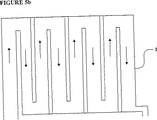
熱交換器(1)を家庭用冷蔵庫に適用する場合、添加剤を保持する水又は任意のその他の流体は、直列的に又は並列的に通路を通って流れ且つ収集器によって集められ、その用途の容量(粘性摩擦)に依存して、スターリング冷却器の低温側に向けられる(図5a、図5b)。四角形又は矩形の断面の通路から成る熱交換器(1)は、その用途の容量に依存して、冷蔵庫の後壁を覆い又は側壁と後壁を覆うように製造する。これら作動の全ては、二次的回路内の流れる流体から環境への熱伝導を可能にする、外部に取り付けた熱交換器(1)に対し及びキャビネット(3)内部で空気から熱エネルギを吸収し得るように製造された熱交換器(1)に対しても有効である。上記の複数の熱交換器(1)の内、低温側にて使用される熱交換器は、キャビネット(3)の内側ライナーと共に製造し又は、別個に製造した後、上記内側ライナーに付着することができる。
【0021】
スターリングヒートポンプ(2)は、低温側にて外部から熱エネルギを吸収し且つ温暖側にて熱エネルギを外部環境に放散する能力を有している。キャビネット(3)の内側ライナーと共に製造された熱交換器(1)により、キャビネット(3)内の空気から吸収された熱エネルギはスターリングヒートポンプ(2)の低温側に運ばれる。温暖側にてヒートポンプ(2)の外部に放散されたこの熱エネルギは、この熱交換器(1)の助けにより、外部環境に運び得るように別個の流体回路により外部に取り付けた熱交換器(1)まで運ばれる。
【0022】
スターリングヒートポンプ(2)と適合可能な熱交換器(1)が冷蔵庫内にて使用される場合、キャビネット(3)内の空気と二次的回路内を循環する流体との間の温度差が小さいとき、熱エネルギを吸収するのに必要な熱伝導表面積が提供される。温度差が小さいときに実現される熱伝導は不可逆性を減少させ、これにより、そのエネルギ消費量を減少させつつ、ヒートポンプ(2)及び冷蔵庫の冷却性能を向上させる。冷蔵庫の後面を完全に覆うように、熱交換器(1)の形態を改変して熱交換器(1)を配置することができるため、冷蔵庫キャビネット(3)内でより均一な温度分布状態を提供することができる。熱交換器(1)が冷蔵庫キャビネット(3)の内側ライナーと一体化されたものとして製造される場合、冷蔵庫の製造コストが削減される。熱成形又はプラスチック射出成形法を利用することにより熱交換器が製造される。
【0023】
熱交換器(1)の全体的な寸法は、スターリングヒートポンプにより優れた性能を得る上で重要な役割を果たす。高さ75cm×幅40cmの熱交換器(1)は四角形又は矩形の断面の通路から成っており、寸法150×50×50cmの冷蔵庫のキャビネット(3)の後壁に単一物として配置し又はそのキャビネット(3)の後壁及び側壁に3つの部分から成る物として配置することができる。
【0024】
この場合、キャビネット(3)の後壁に単一物として配置された熱交換器(1)に対する熱伝導表面積は0.3m2である一方、キャビネット(3)の後壁及び側壁に3つの部分から成る物として配置された熱交換器(1)に対する熱伝導表面積は0.9m2である。流れ状態及び熱伝導特性は双方の形態にて同一であるため、キャビネット(3)内の空気と熱交換器(1)内の流体との間の必要な温度差は、キャビネット(3)の後壁に単一物として配置された熱交換器(1)の場合、約22℃である一方、キャビネット(3)の後壁及び側壁に3つの部分から成る物として配置された熱交換器(1)の場合、この温度差は7.5℃である。
【0025】
理論上、一般に使用されている対数平均温度差(lmtd)法が採用されるとき、熱交換器(1)内の流体の温度は、キャビネット(3)の後壁に単一物として配置された熱交換器(1)の場合、−18℃である一方、キャビネット(3)の後壁及び側壁に3つの部分から成る物として配置された熱交換器(1)の場合、この温度は−3℃である。キャビネット(3)の後壁及び側壁に3つの部分から成る物として配置された熱交換器(1)は、熱伝導表面積を増大させることにより、熱交換器(1)内の上記流体の温度を上昇させ、これにより、ヒートポンプ(2)の性能を向上させ且つエネルギ消費量を減少させるべく使用される。
【0026】
熱交換器(1)がキャビネット(3)の後壁にのみ配置される場合、熱エネルギをキャビネット(3)から吸収することを可能にする流体の温度は、コンプレッサを用いる用途にて使用される蒸発器内の冷媒の蒸発温度に略等しい。
【0027】
熱交換器がキャビネット(3)の後壁及び側壁に3つの部分から成る物として配置されるとき、コストは増大するが、従来のシステムと実際的に比較しなければならない。しかし、エネルギ消費量をも考慮することにより、熱交換器(1)の表面積を最適なものにしなければならない。
【0028】
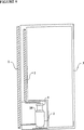
冷蔵庫の後面の全体を覆うような仕方にてキャビネット(3)の内側ライナーと共に、キャビネットから熱エネルギを吸収すべく熱交換器を製造する結果、キャビネット(3)のライナーは通常の用途の場合よりもより低温となる。この場合、キャビネットから熱エネルギを吸収することを可能にする熱交換器は、同様に外側周囲、すなわちキャビネット(3)の環境からも特定量の熱エネルギを吸収し、このことは、冷蔵庫のエネルギ消費量を増すことに繋がる。これを回避するため、真空保温パネル(8)のような、従来の保温材料よりも熱伝導率が低い材料が熱交換器(1)の後側部に配置される(図7)。
【図面の簡単な説明】
【図1】 従来技術の冷却システムの全体図である。
【図2】 自由ピストン型スターリングヒートポンプの全体図である。
【図3】 スターリングヒートポンプを使用するシステムの全体図である。
【図4】 熱交換器の全体図である。
【図5】 5aは、熱交換器内の流体の並列流れ状態を示す図である。
5bは、熱交換器内の流体の直列流れ状態を示す図である。
【図6】 冷蔵庫内に取り付けられた熱交換器の図である。
【図7】 保温材料を有する熱交換器の図である。
1.熱交換器
2.スターリングヒートポンプ
3.キャビネット
4.コンプレッサ
5.凝縮器
6.蒸発器
7.絞り弁
8.真空絶縁パネル
9.低温表面
10.温暖表面
11.キャビネットの内側ライナー
12.キャビネットの外側ライナー
13.保温材、ポリウレタン[0001]
The present invention relates to a refrigerator with a Stirling cycle heat pump in which a heat exchanger is used to remove thermal energy from the refrigerator cooling chamber to the external environment.
[0002]
Cooling systems with compressors, which have been used for years in cooling applications such as refrigerators and air conditioners, mainly draw heat energy from four devices: a compressor and a cooled refrigerator cabinet. It consists of an evaporator used for this purpose, a condenser used for discharging thermal energy, and a throttle valve or capillary tube for adjusting the flow of fluid circulating in the system from high pressure to low pressure. In a domestic refrigerator in which such a conventional system is used, a heat exchanger generally called an evaporator, which serves to suck heat energy from the cooling air inside the refrigerator cabinet, depends on its functional characteristics. It is manufactured from metal tubes of various diameters. The heat energy sucked from the cooling air in the refrigerator cabinet is conveyed to the external environment through a heat exchanger called a condenser after the refrigerant leaving the evaporator is compressed to a high pressure by a compressor. The function of the compressor in the system is to compress low pressure and low temperature refrigerant to high pressure while leaving the evaporator (FIG. 1).
[0003]
The dimensions of the evaporator used in conventional systems are determined after calculating the required surface area according to the cabinet heat gain, the desired air temperature in the cabinet, the refrigerant evaporation temperature, the heat transfer and convection coefficient. In such embodiments, the limited heat transfer surface area requires a large temperature difference, while heat transfer at such a large temperature difference increases irreversibility, which reduces the performance factor of the system. . As a result of research and development by various institutions, it can be seen that the efficiency of compressors used in such systems is approaching an upper limit. However, it is also known that refrigerants or cooling fluids used in refrigerators with compressors destroy the ozone layer and cause global warming.
[0004]
Another thermodynamic cycle used to cool electronics equipment that has been used at low operating temperatures since the 1930s is the Stirling cycle. U.S. Pat. No. 4,858,442, U.S. Pat. No. 4,877,434, U.S. Pat. No. 5,056,317, U.S. Pat. The use of the Stirling cycle in the state of is described. In addition to commonly used Stirling heat pumps with mechanical drives, US Pat. No. 4,183,214, US Pat. No. 4,404,802, US Pat. No. 4,888,951, US Pat. No. 5,642,622 discloses the development of a Stirling heat engine and heat pump based on the free piston principle.
[0005]
Currently, due to its high efficiency, Stirling heat pumps with free pistons have become an important replacement for conventional systems.
A Stirling heat pump is driven by a motor and oscillates at a preselected cycle, a low temperature surface exposed to air that absorbs heat energy from the outside, a warm warm surface that dissipates heat to the air And a piston displacement mechanism for compressing and expanding the gas in the heat pump. The piston driven by the linear electric motor compresses the gas in the heat pump, while isothermal compression is achieved due to heat conduction from the warm surface to the external environment, and the gas temperature remains constant. On the other hand, while the gas expands in the heat pump on the low temperature side of the Stirling heat pump, isothermal expansion occurs when heat energy is drawn from the outside by using the low temperature surface, and the gas temperature remains constant. . Within the range of the thermodynamic cycle described above, the Stirling heat pump has a low temperature surface that can absorb heat energy from the outside and a warm surface that can dissipate heat energy to the outside.
[0006]
In the general technical state in which Stirling heat pumps are used, heat exchangers, which can also be referred to as cold and warm side heat exchangers, are arranged on the cold and warm surfaces mentioned above. When a Stirling heat pump is used instead of a conventional compressor, a heat exchanger must be placed in the refrigerator cabinet to carry the thermal energy in the air to the cold surface, and the heat exchanger It must be connected to the side heat exchanger and a secondary circulation circuit must be formed. The fluid holding water and additives that circulates in the secondary circulation circuit absorbs heat energy from the air in the refrigerator cabinet by flowing through the heat exchanger installed inside. This heat-carrying fluid reaches the cold side heat exchanger located on the Stirling heat pump. Note that the gas (usually helium or nitrogen) in the Stirling heat pump absorbs heat energy from the fluid flowing in the secondary circulation circuit and is absorbed by the fluid from the air in the cabinet for the reasons described above. Heat energy is transferred to the Stirling heat pump by the cold side heat exchanger. Circulation similar to that provided between the heat exchanger mounted on the cabinet and the low temperature side heat exchanger mounted on the Stirling heat pump, and the warm side heat exchanger on the Stirling heat pump Also provided between the refrigerator must be able to perform the cooling function completely.
[0007]
In this case, because of the thermodynamic cycle formed in the Stirling heat pump, the cooling fluid compressed at a constant temperature in the part where the warm side heat exchanger is installed was absorbed from the air in the refrigerator cabinet. Heat energy is conducted with the aid of a warm side heat exchanger to a secondary fluid consisting of water that circulates in an outer heat exchanger circuit mounted externally to the refrigerator. The cycle is complete when the heat energy absorbed by the secondary fluid is dissipated through the heat exchanger to the external environment.
[0008]
Since nitrogen or helium is used as the cooling fluid in the Stirling heat pump and almost water is used in the secondary circuit, this technique has no negative impact on the environment. When free piston technology is used, the lateral load and thus the friction is reduced, so that the performance of the heat pump is improved while the energy consumption of the refrigerator is reduced. In addition to these advantages, the performance of Stirling heat pumps in cooling systems where Stirling heat pumps are used, as in the prior art, the use of a tubular heat exchanger limits the heat transfer surface area. It remains below the value obtained in other cases. In addition, since water is mostly used in the secondary circuit, the heat transfer coefficient in the internal and external heat exchangers is reduced, while this reduces the required heat transfer area. Will increase. In this case, heat exchangers made with metal tubes of various diameters appear to be disadvantageous.
[0009]
It is an object of the present invention to provide a heat exchanger structure that is used to absorb heat energy from a cooled volume and dissipate the absorbed heat energy to the external environment in accordance with a heat pump operating with a Stirling cycle. .
[0010]
An embodiment of a heat exchanger integrated in a refrigerator and suitable for a Stirling heat pump is illustrated in the accompanying drawings.
The flow characteristics of the fluid flowing through the passage in the heat exchanger (1), ie whether the flow is laminar or turbulent, determines the nature of the heat exchanger (1) and the dimensions of the passage. Is important above.
[0011]
The heat exchanger (1) is made of parallel passages having a square or rectangular cross section. The dimensions of the passages are different within a range of 2 × 2 mm to 20 × 20 mm (FIG. 4).
The steady state heat gain of a 150 x 50 x 50 cm refrigerator with only a single temperature compartment kept in 4 cm conventional polyurethane is that no new objects are placed inside and the door is open / closed. It is about 25 W at + 5 ° C. to + 25 ° C. operating condition during the absence time.
[0012]
Unlike the conventional compressor (4), the Stirling heat pump (2) makes it possible to adjust the capacity and for this reason should be taken into account when producing the internal heat exchanger (1) The value is the heat gain during continuous operation. The Stirling heat pump (2) can be operated at a higher capacity to accommodate the added heat load when the door is opened / closed or new items are put into the refrigerator cabinet, and the heat gain is continuous. When the operating level is reached, the refrigeration capacity of the heat pump (2) decreases to the normal value. It is necessary to add these heat loads to the heat gain of continuous operation so that the food in the refrigerator is cooled sufficiently quickly. The maximum operating efficiency of the heat exchanger (1) can be obtained by adding the heat gain generated by opening / closing the door or by putting a new object in the refrigerator cabinet to the heat gain of continuous operation.
[0013]
For refrigerators with dimensions of 150 x 50 x 50 cm, the maximum low temperature obtained by applying an average heat load to the continuous operation heat load due to opening / closing the door or putting a new object in the refrigerator cabinet The capacity of the side heat exchanger (1) is about 40W.
[0014]
Another factor to consider for designing the heat exchanger (1) is the difference between the inlet and outlet temperatures of the fluid flowing in the heat exchanger (1). When this difference is large, the heat conduction in the heat exchanger (1) from the warm part to the cooler part increases, which adversely affects the heat absorption process from the cabinet (3). This problem is solved by keeping the evaporating temperature of the cooling fluid substantially constant in the evaporator, so that heat can be absorbed from the air in the refrigerator in which the conventional compressor is used. This problem is avoided in heat exchangers compatible with the Stirling heat pump (2) by keeping the difference between the inlet and outlet temperatures of the fluid flowing in the heat exchanger (1) at a maximum of 1 ° C. . In a refrigerator having a size of 150 × 50 × 50 cm, the maximum heat load of which is determined as 40 W, the flow rate of the fluid used is approximately 9 to depending on the specific heat so as to realize the temperature difference of 1 ° C. Must be 10 g / s. If more refrigerator volume or lower temperature cooling is desired, this value increases to 25 g / s.
[0015]
In laminar flow conditions, as the passage dimensions become smaller and the flow cross-sectional area becomes narrower, the coefficient of heat transfer for a particular flow rate increases, thus reducing viscous friction resulting in easier flow. Realized and thermal conductivity is favorably affected. In the case of turbulent flow, the reduction of the cross-sectional area has a favorable effect on thermal conductivity and also has a detrimental effect on friction losses. Furthermore, for laminar flow, for a particular geometry, the coefficient of friction and pressure drop decrease with increasing flow rate, and vice versa for turbulent flow.
[0016]
In a 150 × 50 × 50 cm refrigerator, when the flow rate in the heat exchanger (1) designed to have a maximum heat capacity of 40 W is 9 to 10 g / s, the flow is It becomes a layered feature at side lengths of 2.3 to 2.5 mm, and this layered feature is lost and turbulence begins in smaller cross-section passages. If the refrigerator volume is increased or cooler cooling is desired, this limit for the 25 g / s value required to become a 100 W heat load is about 6 mm. In other words, the flow through the passage having a cross section of 6 mm or more is stratified, and the flow through the passage of 6 mm or less is turbulent.
[0017]
If refrigerators with different volumes and different heat-retaining materials are used, the dimensions of the passage portions will be different. For this reason, a detailed analysis is required to determine the cross section of the passage.
[0018]
In addition to the flow characteristics, the geometric shape, i.e. whether the flow passage is square or rectangular, plays an important role in terms of manufacturing method and cost requirements. 9 x 10 g / s in a heat exchanger designed to absorb 40 W of heat energy from air in a 150 x 50 x 50 cm refrigerator with a 10 x 10 mm square or 10 x 40 mm rectangular cross-section passage When used for a flow rate of 9.5 cm / s and 2.3 cm / s in the passage, respectively.
[0019]
When the thermal resistance between the fluid (water + additive) in the heat exchanger (1) and the air in the cabinet (3) is calculated for both types of passages at the same load value, it is almost the same A value is obtained. This is because the coefficient of heat conduction between the inner liner of the cabinet (3) and the air inside the cabinet (3) plays an important role for the thermal resistance.
[0020]
When the heat exchanger (1) is applied to a household refrigerator, the water or any other fluid holding the additive flows through the passage in series or in parallel and is collected by the collector and its use Depending on the capacity (viscous friction) of the Stirling cooler, it is directed to the low temperature side (FIGS. 5a and 5b). Depending on the capacity of the application, the heat exchanger (1) consisting of a square or rectangular cross-section passage is manufactured to cover the rear wall of the refrigerator or to cover the side wall and the rear wall. All of these operations absorb heat energy from the air to the externally mounted heat exchanger (1) and inside the cabinet (3), allowing heat transfer from the flowing fluid in the secondary circuit to the environment. It is also effective for the heat exchanger (1) manufactured in such a way. Of the plurality of heat exchangers (1), the heat exchanger used on the low temperature side is manufactured together with the inner liner of the cabinet (3) or manufactured separately, and then attached to the inner liner. Can do.
[0021]
The Stirling heat pump (2) has the ability to absorb heat energy from the outside on the low temperature side and dissipate the heat energy to the external environment on the warm side. With the heat exchanger (1) manufactured with the inner liner of the cabinet (3), the heat energy absorbed from the air in the cabinet (3) is carried to the low temperature side of the Stirling heat pump (2). The heat energy dissipated to the outside of the heat pump (2) on the warm side is supported by a heat exchanger (1) that is externally attached by a separate fluid circuit so that it can be carried to the external environment. Carried to 1).
[0022]
When the heat exchanger (1) compatible with the Stirling heat pump (2) is used in a refrigerator, the temperature difference between the air in the cabinet (3) and the fluid circulating in the secondary circuit is small Sometimes the heat transfer surface area required to absorb the thermal energy is provided. The heat conduction realized when the temperature difference is small reduces irreversibility, thereby improving the cooling performance of the heat pump (2) and the refrigerator while reducing its energy consumption. Since the heat exchanger (1) can be arranged by modifying the form of the heat exchanger (1) so as to completely cover the rear surface of the refrigerator, a more uniform temperature distribution state in the refrigerator cabinet (3) Can be provided. When the heat exchanger (1) is manufactured as an integral part of the inner liner of the refrigerator cabinet (3), the manufacturing cost of the refrigerator is reduced. Heat exchangers are manufactured by using thermoforming or plastic injection molding methods.
[0023]
The overall dimensions of the heat exchanger (1) play an important role in obtaining superior performance with a Stirling heat pump. The heat exchanger (1) with a height of 75 cm and a width of 40 cm consists of a passage with a square or rectangular cross section and is arranged as a single piece on the rear wall of a refrigerator cabinet (3) with dimensions 150 × 50 × 50 cm or The cabinet (3) can be arranged in three parts on the rear and side walls.
[0024]
In this case, the heat transfer surface area for the heat exchanger (1) arranged as a single object on the rear wall of the cabinet (3) is 0.3 m 2 , while the rear wall and side wall of the cabinet (3) have three parts. The heat conducting surface area for the heat exchanger (1) arranged as a material consisting of is 0.9 m 2 . Since the flow conditions and heat transfer characteristics are the same in both configurations, the required temperature difference between the air in the cabinet (3) and the fluid in the heat exchanger (1) is In the case of a heat exchanger (1) arranged as a single object on the wall, it is approximately 22 ° C., while the heat exchanger (1 as arranged in three parts on the rear and side walls of the cabinet (3) ), This temperature difference is 7.5 ° C.
[0025]
Theoretically, when the commonly used logarithmic mean temperature difference (lmtd) method is adopted, the temperature of the fluid in the heat exchanger (1) was placed as a single object on the rear wall of the cabinet (3). In the case of the heat exchanger (1), it is −18 ° C., whereas in the case of the heat exchanger (1) arranged as a three part on the rear and side walls of the cabinet (3), this temperature is −3 ° C. The heat exchanger (1), which is arranged in three parts on the rear and side walls of the cabinet (3), increases the temperature of the fluid in the heat exchanger (1) by increasing the heat transfer surface area. It is used to raise and thereby improve the performance of the heat pump (2) and reduce energy consumption.
[0026]
If the heat exchanger (1) is located only on the rear wall of the cabinet (3), the temperature of the fluid that allows heat energy to be absorbed from the cabinet (3) is used in applications that use a compressor. It is approximately equal to the evaporation temperature of the refrigerant in the evaporator.
[0027]
When the heat exchanger is arranged in three parts on the rear and side walls of the cabinet (3), the cost increases but must be compared practically with conventional systems. However, the surface area of the heat exchanger (1) must be optimized by taking into account the energy consumption.
[0028]
As a result of manufacturing the heat exchanger to absorb the heat energy from the cabinet together with the inner liner of the cabinet (3) in such a way as to cover the entire rear surface of the refrigerator, the liner of the cabinet (3) is more than in normal use Will also be colder. In this case, the heat exchanger that makes it possible to absorb the heat energy from the cabinet likewise absorbs a certain amount of heat energy from the outside environment, i.e. the environment of the cabinet (3), which means that the energy of the refrigerator. It leads to increase consumption. In order to avoid this, a material having a lower thermal conductivity than the conventional heat insulation material such as the vacuum heat insulation panel (8) is disposed on the rear side of the heat exchanger (1) (FIG. 7).
[Brief description of the drawings]
FIG. 1 is an overall view of a prior art cooling system.
FIG. 2 is an overall view of a free piston type Stirling heat pump.
FIG. 3 is an overall view of a system using a Stirling heat pump.
FIG. 4 is an overall view of a heat exchanger.
FIG. 5a is a view showing a parallel flow state of fluids in a heat exchanger.
5b is a diagram showing a serial flow state of fluid in the heat exchanger.
FIG. 6 is a view of a heat exchanger installed in the refrigerator.
FIG. 7 is a diagram of a heat exchanger having a heat retaining material.
1. 1.
Claims (7)
前記ヒートポンプの最大運転容量を、前記冷蔵庫キャビネットドアを開ける/閉じることにより且つ前記冷蔵庫キャビネット(3)内に新たな物を入れることにより発生される熱利得を連続的運転の熱利得に加えることにより、計算し、
前記熱交換器(1)は、熱成形またはプラスチック射出成形され、前記低温側にて使用される前記熱交換器(1)が前記キャビネット(3)の内側ライナーと一体に製造されるとともに、熱伝導率が従来のポリウレタンよりも小さい真空保温パネル(8)が前記熱交換器(1)の後側部に配置され、前記熱交換器(1)内の流体が並列に流れ、並列に流れるいずれの流路を通っても前記熱交換器(1)の入口から出口までの距離が略等しくなるように構成されたことを特徴とする、冷蔵庫。A refrigerator (3), a refrigerator cabinet door, a Stirling heat pump (2), and a heat exchanger (1) suitable for the Stirling heat pump (2) having a plurality of side surfaces adjacent to and connected in parallel to each other Water, or any other fluid holding the additive, flows through the heat exchanger (1) and is collected by a passage and supplied towards the cold side of the Stirling heat pump (2) In a refrigerator equipped with an exchanger (1),
By adding the heat gain generated by opening / closing the refrigerator cabinet door and putting a new object in the refrigerator cabinet (3) to the heat gain of continuous operation. Calculate,
The heat exchanger (1) is thermoformed or plastic injection molded, and the heat exchanger (1) used on the low temperature side is manufactured integrally with an inner liner of the cabinet (3) , and heat A vacuum heat insulation panel (8) having a conductivity lower than that of a conventional polyurethane is disposed on the rear side of the heat exchanger (1), and the fluid in the heat exchanger (1) flows in parallel, A refrigerator characterized in that the distance from the inlet to the outlet of the heat exchanger (1) is substantially equal even when passing through the flow path .
Applications Claiming Priority (3)
| Application Number | Priority Date | Filing Date | Title |
|---|---|---|---|
| TR99/03005 | 1999-12-01 | ||
| TR9903005 | 1999-12-01 | ||
| PCT/TR2000/000061 WO2001040724A1 (en) | 1999-12-01 | 2000-11-30 | The refrigerator |
Publications (3)
| Publication Number | Publication Date |
|---|---|
| JP2003515719A JP2003515719A (en) | 2003-05-07 |
| JP2003515719A5 JP2003515719A5 (en) | 2011-07-21 |
| JP4902080B2 true JP4902080B2 (en) | 2012-03-21 |
Family
ID=21622258
Family Applications (1)
| Application Number | Title | Priority Date | Filing Date |
|---|---|---|---|
| JP2001542147A Expired - Fee Related JP4902080B2 (en) | 1999-12-01 | 2000-11-30 | refrigerator |
Country Status (7)
| Country | Link |
|---|---|
| EP (1) | EP1234149B1 (en) |
| JP (1) | JP4902080B2 (en) |
| AT (1) | ATE334363T1 (en) |
| AU (1) | AU1750501A (en) |
| DE (1) | DE60029616T2 (en) |
| TR (1) | TR200201186T2 (en) |
| WO (1) | WO2001040724A1 (en) |
Citations (2)
| Publication number | Priority date | Publication date | Assignee | Title |
|---|---|---|---|---|
| US2573583A (en) * | 1947-01-03 | 1951-10-30 | Kold Hold Mfg Co | Plate type refrigerant evaporator |
| US5642622A (en) * | 1995-08-17 | 1997-07-01 | Sunpower, Inc. | Refrigerator with interior mounted heat pump |
Family Cites Families (22)
| Publication number | Priority date | Publication date | Assignee | Title |
|---|---|---|---|---|
| US2059840A (en) * | 1934-08-21 | 1936-11-03 | Gen Electric | Refrigerating machine |
| US2690653A (en) * | 1952-08-14 | 1954-10-05 | Dole Refrigerating Co | Stamped plate |
| US4183214A (en) | 1977-05-05 | 1980-01-15 | Sunpower, Inc. | Spring and resonant system for free-piston Stirling engines |
| JPS55146394A (en) * | 1979-05-01 | 1980-11-14 | Du Pont | Heat exchanger and heat exchanger element |
| US4404802A (en) | 1981-09-14 | 1983-09-20 | Sunpower, Inc. | Center-porting and bearing system for free-piston stirling engines |
| DE3204556C2 (en) * | 1982-02-10 | 1986-11-13 | Bosch-Siemens Hausgeräte GmbH, 8000 München | Heat-insulated housing, especially for household refrigerated cabinets or the like |
| JPS60101473A (en) * | 1983-11-08 | 1985-06-05 | 松下冷機株式会社 | Heat-insulating box body of refrigerator, etc. |
| JPS61202068A (en) * | 1985-03-04 | 1986-09-06 | 松下冷機株式会社 | Refrigerator |
| JPS61262577A (en) * | 1985-05-17 | 1986-11-20 | 松下冷機株式会社 | Refrigerator |
| US4955435A (en) * | 1987-04-08 | 1990-09-11 | Du Pont Canada, Inc. | Heat exchanger fabricated from polymer compositions |
| US4877434A (en) | 1987-06-09 | 1989-10-31 | Cryodynamics, Inc. | Cryogenic refrigerator |
| US4858442A (en) | 1988-04-29 | 1989-08-22 | Inframetrics, Incorporated | Miniature integral stirling cryocooler |
| US5056317A (en) | 1988-04-29 | 1991-10-15 | Stetson Norman B | Miniature integral Stirling cryocooler |
| US4888951A (en) | 1989-07-03 | 1989-12-26 | Sunpower, Inc. | Phase synchronization and vibration cancellation for free piston Stirling machines |
| JPH0788985B2 (en) | 1990-01-17 | 1995-09-27 | 三菱電機株式会社 | refrigerator |
| JP2998852B2 (en) * | 1991-04-03 | 2000-01-17 | 松下冷機株式会社 | Refrigerator refrigerator control device |
| FR2679020A1 (en) * | 1991-07-12 | 1993-01-15 | Severini Bruno | Transportable and dismantleable refrigerating device for market (fair) stall displays |
| KR940011324B1 (en) * | 1991-10-10 | 1994-12-05 | 주식회사 금성사 | Stiling cycle |
| GB9509242D0 (en) * | 1995-05-05 | 1995-06-28 | Bundy Int Ltd | Refrigerating appliances |
| JPH10148411A (en) * | 1996-11-15 | 1998-06-02 | Sanyo Electric Co Ltd | Stirling refrigerating system |
| US5964101A (en) * | 1996-12-10 | 1999-10-12 | Edward R. Schulak | Energy transfer system for refrigerator/freezer components |
| TW426798B (en) * | 1998-02-06 | 2001-03-21 | Sanyo Electric Co | Stirling apparatus |
-
2000
- 2000-11-30 AT AT00980211T patent/ATE334363T1/en not_active IP Right Cessation
- 2000-11-30 DE DE60029616T patent/DE60029616T2/en not_active Expired - Lifetime
- 2000-11-30 EP EP00980211A patent/EP1234149B1/en not_active Expired - Lifetime
- 2000-11-30 WO PCT/TR2000/000061 patent/WO2001040724A1/en active IP Right Grant
- 2000-11-30 AU AU17505/01A patent/AU1750501A/en not_active Abandoned
- 2000-11-30 TR TR2002/01186T patent/TR200201186T2/en unknown
- 2000-11-30 JP JP2001542147A patent/JP4902080B2/en not_active Expired - Fee Related
Patent Citations (2)
| Publication number | Priority date | Publication date | Assignee | Title |
|---|---|---|---|---|
| US2573583A (en) * | 1947-01-03 | 1951-10-30 | Kold Hold Mfg Co | Plate type refrigerant evaporator |
| US5642622A (en) * | 1995-08-17 | 1997-07-01 | Sunpower, Inc. | Refrigerator with interior mounted heat pump |
Also Published As
| Publication number | Publication date |
|---|---|
| TR200201186T2 (en) | 2002-08-21 |
| DE60029616D1 (en) | 2006-09-07 |
| JP2003515719A (en) | 2003-05-07 |
| WO2001040724A1 (en) | 2001-06-07 |
| AU1750501A (en) | 2001-06-12 |
| EP1234149B1 (en) | 2006-07-26 |
| EP1234149A1 (en) | 2002-08-28 |
| ATE334363T1 (en) | 2006-08-15 |
| DE60029616T2 (en) | 2007-07-26 |
Similar Documents
| Publication | Publication Date | Title |
|---|---|---|
| CN100371662C (en) | Refrigerator | |
| JPS5915783A (en) | Cooling device for compressor of refrigerator | |
| KR20030004899A (en) | Refrigerator with condenser and backcover in one | |
| WO2002016835A1 (en) | Sterling refrigerating system and cooling device | |
| CN112944770B (en) | Refrigerator and refrigerating system thereof | |
| KR970001837B1 (en) | Refrigerator | |
| JP6101926B2 (en) | refrigerator | |
| JP3826998B2 (en) | Stirling refrigeration system and Stirling refrigerator | |
| JP4902080B2 (en) | refrigerator | |
| CN116638912A (en) | Battery cooling system and battery cooling method capable of reducing energy consumption | |
| CN112611133B (en) | Regenerative refrigerator and refrigerator adopting same | |
| JP2714155B2 (en) | Cooling room | |
| WO2017130856A1 (en) | Refrigerator | |
| JP5401866B2 (en) | refrigerator | |
| CN215675977U (en) | Cryogenic medicine cabinet based on gas expansion technology | |
| CN113720074B (en) | Refrigeration equipment, control method, control device and computer readable storage medium | |
| CN220585308U (en) | Energy-storage liquid-cooling air conditioning unit | |
| CN214199336U (en) | Refrigerating box | |
| CN102692111B (en) | Freezer | |
| JP7416991B1 (en) | refrigerator | |
| JP2023041133A (en) | refrigerator | |
| JP3433175B2 (en) | Cold storage | |
| JPH07180938A (en) | Pulse tube refrigerator | |
| JP2021179278A (en) | refrigerator | |
| JP2022123224A (en) | refrigerator |
Legal Events
| Date | Code | Title | Description |
|---|---|---|---|
| A621 | Written request for application examination |
Free format text: JAPANESE INTERMEDIATE CODE: A621 Effective date: 20070726 |
|
| A131 | Notification of reasons for refusal |
Free format text: JAPANESE INTERMEDIATE CODE: A131 Effective date: 20100129 |
|
| A601 | Written request for extension of time |
Free format text: JAPANESE INTERMEDIATE CODE: A601 Effective date: 20100428 |
|
| A602 | Written permission of extension of time |
Free format text: JAPANESE INTERMEDIATE CODE: A602 Effective date: 20100511 |
|
| A521 | Request for written amendment filed |
Free format text: JAPANESE INTERMEDIATE CODE: A523 Effective date: 20100531 |
|
| A131 | Notification of reasons for refusal |
Free format text: JAPANESE INTERMEDIATE CODE: A131 Effective date: 20101202 |
|
| A601 | Written request for extension of time |
Free format text: JAPANESE INTERMEDIATE CODE: A601 Effective date: 20110223 |
|
| A602 | Written permission of extension of time |
Free format text: JAPANESE INTERMEDIATE CODE: A602 Effective date: 20110302 |
|
| A524 | Written submission of copy of amendment under article 19 pct |
Free format text: JAPANESE INTERMEDIATE CODE: A524 Effective date: 20110602 |
|
| TRDD | Decision of grant or rejection written | ||
| RD02 | Notification of acceptance of power of attorney |
Free format text: JAPANESE INTERMEDIATE CODE: A7422 Effective date: 20111208 |
|
| A01 | Written decision to grant a patent or to grant a registration (utility model) |
Free format text: JAPANESE INTERMEDIATE CODE: A01 Effective date: 20111215 |
|
| A01 | Written decision to grant a patent or to grant a registration (utility model) |
Free format text: JAPANESE INTERMEDIATE CODE: A01 |
|
| A61 | First payment of annual fees (during grant procedure) |
Free format text: JAPANESE INTERMEDIATE CODE: A61 Effective date: 20111228 |
|
| R150 | Certificate of patent or registration of utility model |
Free format text: JAPANESE INTERMEDIATE CODE: R150 |
|
| FPAY | Renewal fee payment (event date is renewal date of database) |
Free format text: PAYMENT UNTIL: 20150113 Year of fee payment: 3 |
|
| R250 | Receipt of annual fees |
Free format text: JAPANESE INTERMEDIATE CODE: R250 |
|
| LAPS | Cancellation because of no payment of annual fees |