JP4901257B2 - Stepping motor - Google Patents
Stepping motor Download PDFInfo
- Publication number
- JP4901257B2 JP4901257B2 JP2006087208A JP2006087208A JP4901257B2 JP 4901257 B2 JP4901257 B2 JP 4901257B2 JP 2006087208 A JP2006087208 A JP 2006087208A JP 2006087208 A JP2006087208 A JP 2006087208A JP 4901257 B2 JP4901257 B2 JP 4901257B2
- Authority
- JP
- Japan
- Prior art keywords
- yoke
- plate portion
- annular
- cylindrical
- annular collar
- Prior art date
- Legal status (The legal status is an assumption and is not a legal conclusion. Google has not performed a legal analysis and makes no representation as to the accuracy of the status listed.)
- Expired - Fee Related
Links
Images


Description
本発明は、ステッピングモータに関し、特に、コイル巻線のヨーク組み構造に関する。 The present invention relates to a stepping motor, and more particularly to a yoke assembly structure of coil winding.
特開2003−324892においては、リードスクリユウ部を持つモータ回転軸を備えたPM型ステッピングモータが開示されている。このモータのクロポール形アウターステータは、内周側の複数の極歯と外周側の胴板部で区画された第1環状空部に第1コイル巻線を収容する第1ヨークと、内周側に複数の極歯を持ち第1コイル巻線を塞ぐ端板としての第2ヨークと、内周側の複数の極歯と第1ヨークの胴板部とで区画された第2環状空部に第2コイル巻線を収容する第3ヨークと、内周側に複数の極歯を持ち第2コイル巻線を塞ぐ端板としての第4ヨークとを備えている。 Japanese Patent Application Laid-Open No. 2003-324892 discloses a PM type stepping motor having a motor rotating shaft having a lead screw portion. A cropole-type outer stator of the motor includes a first yoke that houses a first coil winding in a first annular cavity defined by a plurality of pole teeth on the inner peripheral side and a body plate part on the outer peripheral side, and an inner peripheral side A second yoke as an end plate that closes the first coil winding with a plurality of pole teeth, and a second annular cavity defined by a plurality of pole teeth on the inner peripheral side and a body plate portion of the first yoke. A third yoke that houses the second coil winding, and a fourth yoke as an end plate that has a plurality of pole teeth on the inner peripheral side and closes the second coil winding.
第1ヨークの胴板部は第1コイル巻線の励磁による磁路を形成するのみならず、第2コイル巻線の励磁に磁路を形成するため、ヨーク組みが4枚の軟鉄板で構成できる利点がある。
しかしながら、第1コイル巻線の励磁による磁路形成においては第1ヨークの内側面と第2ヨークの端面との接合面が高磁気抵抗箇所として存在するのに対し、第2コイル巻線の励磁による磁路形成においては第1ヨークの内側面と第4ヨークの端面との接合の外、第1ヨークの内側面と第3ヨークの端面との接合も高磁気抵抗箇所として存在しているので、第2コイル巻線の励磁による磁路の磁気抵抗の方が高くなり、第1相と第2相との交互にディテントトルクの差が生じ、ステップ精度のバラツキを招く。 However, in the magnetic path formation by exciting the first coil winding, the joint surface between the inner surface of the first yoke and the end surface of the second yoke exists as a high magnetic resistance portion, whereas the excitation of the second coil winding is performed. In the formation of the magnetic path, the junction between the inner surface of the first yoke and the end surface of the fourth yoke and the junction between the inner surface of the first yoke and the end surface of the third yoke also exist as high magnetic resistance locations. The magnetic resistance of the magnetic path due to the excitation of the second coil winding becomes higher, resulting in a difference in detent torque between the first phase and the second phase, resulting in variations in step accuracy.
また、このクロポール形アウターステータでは第1ヨークに第1コイル巻線を組み付けてから第2ヨークと第3ヨークとを順次固定し、第2コイル巻線を組み付けてから第4ヨークを固定するものであるため、都合3箇所の接合部分で加締等により固定する必要がある。 In this cropole type outer stator, the first coil winding is assembled to the first yoke, the second yoke and the third yoke are sequentially fixed, and the second coil winding is assembled, and then the fourth yoke is fixed. Therefore, it is necessary to fix it by caulking or the like at three joint portions for convenience.
そこで、上記問題点に鑑み、本発明の課題は、ヨーク組みを仕上げた後に2つのコイル巻線を組み付けることができ、しかも各相の磁気抵抗の平等化を実現できるステッピングモータを提供することにある。 Therefore, in view of the above problems, an object of the present invention is to provide a stepping motor capable of assembling two coil windings after finishing a yoke assembly and realizing equalization of the magnetic resistance of each phase. is there.
上記課題を解決するため、請求項1に係る発明は、環状鍔の内周縁に切り起されて環状列に並ぶ複数の極歯を持つヨークの4個をインサート成形し、第1ヨークの極歯と第2ヨークの極歯とを非接触の噛み合わせ状態で連結し、第3ヨークの極歯と第4ヨークの極歯とを非接触の噛み合わせ状態で連結し、第2ヨークの環状鍔と第3ヨークの環状鍔とを背合せ状態で連結して成るモールドヨークと、第1ヨークの環状鍔と第2ヨークの環状鍔との間に巻装した第1コイル巻線と、第3ヨークの環状鍔と第4ヨークの環状鍔との間に巻装した第2コイル巻線と、モールドヨークが嵌入して各環状鍔の外周縁が内側面に接合する胴板部を持つ筒状ヨークとを備えたステッピングモータにおいて、モールドヨークは第4ヨーク側から筒状ヨークの開口を介して突出した樹脂製軸受ホルダーを一体的に有し、筒状ヨークは胴板部から折り曲げ成形されて第1ヨークの環状鍔の外表面と重なる底板部を有し、胴板部と底板部とが成す角部の内側に切り込み部が形成されることで、底板部に磁束を通り難くし第1ヨークに磁束を通すことで、第1ヨークと第4ヨークとが同等の磁束を通すことを特徴とする。
In order to solve the above-described problem, the invention according to
第1乃至第4のヨークはモールドヨークとして1部品のヨーク組みに予め仕上げることができるため、このモールドヨークに対して第1コイル巻線と第2コイル巻線を組み付けることができる。また、このモールドヨークと筒状ヨークとの組み合わせにおいては、第1乃至第4のヨークのいずれもの環状鍔の外周縁が筒状ヨークの胴板部の内側面と接合し、各相の高磁気抵抗箇所が2箇所で平等化するので、ステップ精度のバラツキを抑制できる。更に、筒状ヨークは胴板部から折り曲げ形成されて第1ヨークの環状鍔の外表面と重なる底板部を有し、胴板部と底板部とが成す角部の内側に切り込み部が形成されているため、この切り込み部の存在により角部が高磁気抵抗箇所となり、胴板部内の磁束が底板部内へは通り難く、専ら第1ヨークの環状鍔内を通ることなる。このため、第1ヨークは筒状ヨークの開口側の第4ヨークと同等の磁束を通すので、ステップ精度のバラツキを一層抑制できる。 Since the first to fourth yokes can be finished in advance as a single yoke assembly as a mold yoke, the first coil winding and the second coil winding can be assembled to the mold yoke. Further, in this combination of the mold yoke and the cylindrical yoke, the outer peripheral edge of the annular flange of any of the first to fourth yokes is joined to the inner side surface of the body plate portion of the cylindrical yoke, and each phase has a high magnetic property. Since the resistance locations are equalized at two locations, variations in step accuracy can be suppressed. Further, the cylindrical yoke has a bottom plate portion that is bent from the body plate portion and overlaps the outer surface of the annular flange of the first yoke, and a cut portion is formed inside the corner portion formed by the body plate portion and the bottom plate portion. Therefore, the corner portion becomes a high magnetic resistance location due to the presence of the cut portion, and the magnetic flux in the body plate portion does not easily pass into the bottom plate portion, and passes only through the annular flange of the first yoke. For this reason, since the first yoke passes a magnetic flux equivalent to that of the fourth yoke on the opening side of the cylindrical yoke, the variation in the step accuracy can be further suppressed.
請求項2に係る発明は、環状鍔の内周縁に切り起されて環状列に並ぶ複数の極歯を持つヨークの4個をインサート成形し、第1ヨークの極歯と第2ヨークの極歯とを非接触の噛み合わせ状態で連結し、第3ヨークの極歯と第4ヨークの極歯とを非接触の噛み合わせ状態で連結し、第2ヨークの環状鍔と第3ヨークの環状鍔とを背合せ状態で連結して成るモールドヨークと、第1ヨークの環状鍔と第2ヨークの環状鍔との間に巻装した第1コイル巻線と、第3ヨークの環状鍔と第4ヨークの環状鍔との間に巻装した第2コイル巻線と、モールドヨークが嵌入して各環状鍔の外周縁が内側面に接合する胴板部を持つ筒状ヨークとを備えたステッピングモータにおいて、モールドヨークは第4ヨーク側から筒状ヨークの開口を介して突出した樹脂製軸受ホルダーを一体的に有し、筒状ヨークは胴板部から折り曲げ成形されて第1ヨークの環状鍔の外表面と重なる底板部を有し、底板部のうち当該底板部と胴板部とが成す角部寄りに当該角部を巡る複数の孔が環状列設されることで、底板部に磁束を通り難くし第1ヨークに磁束を通すことで、第1ヨークと第4ヨークとが同等の磁束を通すことを特徴とする。 The invention according to claim 2 insert-molds four yokes having a plurality of pole teeth that are cut and raised at the inner peripheral edge of the annular collar and arranged in an annular row, and the pole teeth of the first yoke and the pole teeth of the second yoke Are connected in a non-contact meshing state, and the pole teeth of the third yoke and the pole teeth of the fourth yoke are connected in a non-contact meshing state, and the annular collar of the second yoke and the annular collar of the third yoke are connected. Are connected in a back-to-back state, a first coil winding wound between an annular rod of the first yoke and an annular rod of the second yoke, an annular rod of the third yoke and the fourth Stepping motor comprising a second coil winding wound between an annular flange of the yoke and a cylindrical yoke having a body plate portion in which a mold yoke is fitted and an outer peripheral edge of each annular flange is joined to the inner surface The mold yoke is made of resin that protrudes from the fourth yoke side through the opening of the cylindrical yoke. A receiving holder is integrally formed, and the cylindrical yoke has a bottom plate portion that is bent from the body plate portion and overlaps with the outer surface of the annular flange of the first yoke. Among the bottom plate portions, the bottom plate portion, the body plate portion, in Rukoto plurality of holes around the corner is annular arrayed at a corner near formed by, by passing a magnetic flux in the first yoke hardly passes magnetic flux to the bottom plate portion, and the first yoke and the fourth yoke It is characterized by passing an equivalent magnetic flux .
この発明においても、第1乃至第4のヨークはモールドヨークとして1部品のヨーク組みに予め仕上げることができるため、このモールドヨークに対して第1コイル巻線と第2コイル巻線を組み付けることができる。また、このモールドヨークと筒状ヨークとの組み合わせにおいては、第1乃至第4のヨークのいずれもの環状鍔の外周縁が筒状ヨークの胴板部の内側面と接合し、各相の高磁気抵抗箇所が2箇所で平等化するので、ステップ精度のバラツキを抑制できる。更に、筒状ヨークは胴板部から折り曲げ成形されて第1ヨークの環状鍔の外表面と重なる底板部を有し、底板部のうち当該底板部と胴板部とが成す角部寄りに当該角部を巡る複数の孔が環状列設されているため、角部付近が高磁気抵抗箇所となり、胴板部内の磁束が底板部内へは通り難く、専ら第1ヨークの環状鍔内を通ることなる。このため、第1ヨークは筒状ヨークの開口側の第4ヨークと同等の磁束を通すので、ステップ精度のバラツキを一層抑制できる。 Also in this invention, since the first to fourth yokes can be finished in advance as a single yoke assembly as a mold yoke, the first coil winding and the second coil winding can be assembled to the mold yoke. it can. Further, in this combination of the mold yoke and the cylindrical yoke, the outer peripheral edge of the annular flange of any of the first to fourth yokes is joined to the inner side surface of the body plate portion of the cylindrical yoke, and each phase has a high magnetic property. Since the resistance locations are equalized at two locations, variations in step accuracy can be suppressed. Further, the cylindrical yoke has a bottom plate portion that is bent from the body plate portion and overlaps with the outer surface of the annular collar of the first yoke, and the bottom yoke portion is located near the corner portion formed by the bottom plate portion and the body plate portion. Since a plurality of holes around the corner are arranged in a ring, the vicinity of the corner becomes a high magnetic resistance location, and the magnetic flux in the body plate does not easily pass into the bottom plate, but only passes through the annular collar of the first yoke. Become. For this reason, since the first yoke passes a magnetic flux equivalent to that of the fourth yoke on the opening side of the cylindrical yoke, the variation in the step accuracy can be further suppressed.
請求項3に係る発明は、環状鍔の内周縁に切り起されて環状列に並ぶ複数の極歯を持つヨークの4個をインサート成形し、第1ヨークの極歯と第2ヨークの極歯とを非接触の噛み合わせ状態で連結し、第3ヨークの極歯と第4ヨークの極歯とを非接触の噛み合わせ状態で連結し、第2ヨークの環状鍔と第3ヨークの環状鍔とを背合せ状態で連結して成るモールドヨークと、第1ヨークの環状鍔と第2ヨークの環状鍔との間に巻装した第1コイル巻線と、第3ヨークの環状鍔と第4ヨークの環状鍔との間に巻装した第2コイル巻線と、モールドヨークが嵌入して各環状鍔の外周縁が内側面に接合する胴板部を持つ筒状ヨークと、シャフト及びシャフトが嵌入されたマグネットからなるインナーロータとを備えたステッピングモータにおいて、モールドヨークは第4ヨーク側から筒状ヨークの開口を介して突出した樹脂製軸受ホルダーを一体的に有し、筒状ヨークは胴板部から折り曲げ成形されて第1ヨークの環状鍔の外表面と重なる複数の突片を有し、突片にはシャフトを支持するフレームが支持されることを特徴とする。 According to a third aspect of the present invention, four yokes having a plurality of pole teeth cut and raised at the inner peripheral edge of the annular collar and arranged in an annular row are insert-molded, and the pole teeth of the first yoke and the pole teeth of the second yoke are formed. Are connected in a non-contact meshing state, and the pole teeth of the third yoke and the pole teeth of the fourth yoke are connected in a non-contact meshing state, and the annular collar of the second yoke and the annular collar of the third yoke are connected. Are connected in a back-to-back state, a first coil winding wound between an annular rod of the first yoke and an annular rod of the second yoke, an annular rod of the third yoke and the fourth A second coil winding wound between an annular flange of the yoke, a cylindrical yoke having a body plate portion in which a mold yoke is fitted and an outer peripheral edge of each annular flange is joined to an inner surface ; a shaft and a shaft; in the stepping motor having an inner rotor comprising a fitting has been a magnet, motor The lud yoke integrally has a resin bearing holder protruding from the fourth yoke side through the opening of the cylindrical yoke, and the cylindrical yoke is formed by bending from the body plate portion to form the outer surface of the annular flange of the first yoke. have a plurality of projecting pieces that overlap, the projecting piece, characterized in that the frame for supporting the shaft is supported.
この発明においても、第1乃至第4のヨークはモールドヨークとして1部品のヨーク組みに予め仕上げることができるため、このモールドヨークに対して第1コイル巻線と第2コイル巻線を組み付けることができる。また、このモールドヨークと筒状ヨークとの組み合わせにおいては、第1乃至第4のヨークのいずれもの環状鍔の外周縁が筒状ヨークの胴板部の内側面と接合し、各相の高磁気抵抗箇所が2箇所で平等化するので、ステップ精度のバラツキを抑制できる。更に、筒状ヨークは胴板部から折り曲げ成形されて第1ヨークの環状鍔の外表面と重なる複数の突片を有し、事実上無底であるため、胴板部内の磁束は第1ヨークの環状鍔内を必ず通ることになる。このため、第1ヨークは筒状ヨークの開口側の第4ヨークと同等の磁束を通すので、ステップ精度のバラツキを一層抑制できる。 Also in this invention, since the first to fourth yokes can be finished in advance as a single yoke assembly as a mold yoke, the first coil winding and the second coil winding can be assembled to the mold yoke. it can. Further, in this combination of the mold yoke and the cylindrical yoke, the outer peripheral edge of the annular flange of any of the first to fourth yokes is joined to the inner side surface of the body plate portion of the cylindrical yoke, and each phase has a high magnetic property. Since the resistance locations are equalized at two locations, variations in step accuracy can be suppressed. Furthermore, since the cylindrical yoke has a plurality of projecting pieces that are bent from the body plate portion and overlaps the outer surface of the annular flange of the first yoke, and is virtually bottomless, the magnetic flux in the body plate portion is You will always pass through the ring cage. For this reason, since the first yoke passes a magnetic flux equivalent to that of the fourth yoke on the opening side of the cylindrical yoke, the variation in the step accuracy can be further suppressed.
本発明では、インサート成形で得たモールドヨークに2つのコイル巻線を組み付けることができ、しかも底板部を有する筒状ヨークを使用しても各相の磁気抵抗を平等化してステップ精度のバラツキを抑制できる。 In the present invention, two coil windings can be assembled to a mold yoke obtained by insert molding, and even if a cylindrical yoke having a bottom plate portion is used , the magnetic resistance of each phase is equalized and step accuracy varies. Can be suppressed.
次に、本発明の実施形態を添付図面に基づいて説明する。 Next, embodiments of the present invention will be described with reference to the accompanying drawings.
図1は本発明の実施例1に係るリードスクリュウ・モータを示す斜視図、図2は同モータの軸受ホルダーに対する軸受抜け止め板の取着態様を示す斜視図、図3は同リードスクリュウ・モータを示す断面図、図4(A)は同リードスクリュウ・モータにおける筒状ケースを示す斜視図、図4(B)は筒状ケースの部分縦断面図である。 1 is a perspective view showing a lead screw motor according to a first embodiment of the present invention, FIG. 2 is a perspective view showing how a bearing retaining plate is attached to a bearing holder of the motor, and FIG. 3 is a lead screw motor. 4A is a perspective view showing a cylindrical case in the lead screw motor, and FIG. 4B is a partial longitudinal sectional view of the cylindrical case.
本例のリードスクリュウ・モータは、モータ本体1から突出してリードスクリュウ(図示せず)が形成されたモータシャフト2と、モータ本体1の筒状ケース(筒状ヨーク)6の底板部6aに支持されたフレーム3に取着し、シャフト2の先端縮径部2aを回転自在に支承する軸受4とを有する。
The lead screw motor of this example is supported by a
モータ本体1はPM型ステッピングモータで、シャフト2及びこれが嵌入されたマグネット5から成るインナーロータと、筒状ケース6に嵌入されたモールドヨーク7(A相アウターヨーク7aa,A相インナーヨーク7ab,B相インナーヨーク7ba,B相アウターヨーク7bb)及び極歯間絶縁樹脂M1,M2上に巻装されたコイル巻線(A相コイル9a,B相コイル9b)から成るクロポール形アウターステ―タとを有する。このモールドヨーク7は、インサート成形によって、A相アウターヨーク(第1ヨーク)7aaの極歯K1とA相インナーヨーク(第2ヨーク)7abの極歯K2とを極歯間樹脂M1を介して噛み合わせ状態で連結し、B相インナーヨーク(第3ヨーク)7baの極歯K3とB相アウターヨーク(第4ヨーク)7bbの極歯K4とを極歯間絶縁樹脂M2を介して噛み合わせ状態で連結し、A相インナーヨーク7abの環状鍔F2とB相インナーヨーク7baの環状鍔F3とを極歯間絶縁樹脂M1,M2を介して背合わせ状態で連結して成る。A相アウターヨーク7aaの環状鍔F1とA相インナーヨーク7abの環状鍔F2との間にA相コイル巻線9aが巻装され、B相インナーヨーク7baの環状部F3とB相アウターヨーク7bbの環状部F4との間にB相コイル巻線9bが巻装されている。このモールドヨーク7は筒状ケース6に嵌入しており、環状鍔F1〜F4の外周縁が胴板部6bの内側面に接合している。
The
シャフト2はその基端部の抱球穴2b内とピボット軸受11の球受け穴11a内とに嵌る鋼球10を介して回転自在にピボット軸受11に支承されている。このピボット軸受11は、絶縁樹脂部M2と一体的に形成されて筒状ケース6の開口から突出した軸受ホルダー12の軸受収容孔12aに嵌入し、軸受抜け止め板13により軸方向に押圧付勢されて抜け止めされている。
The
軸受ホルダー12は、相平行した一対の案内縁辺部X1,X2とこれらに直交して相平行な一対の案内縁辺部Y1,Y2を持つ略矩形状のフランジ部12bを有する。軸受抜け止め板13も略矩形状で、その中央部にはピボット軸受11の端面11bの中央部に圧接するための板ばね片13aが切り起こし形成されている。軸受抜け止め板13において、板ばね片13aを通る左右対称軸を挟んだ一対の縁辺は2度折り曲げ形成された断面略コ字状であり、案内縁辺部X1,X2或いは案内縁辺部Y1,Y2に差し込むためのスライド溝を持つ挟み込み縁辺部W1,W2となっている。一対の案内縁辺部X1,X2或いは一対の案内縁辺部Y1,Y2と挟み込み縁辺部W1,W2とが軸受抜け止め板13を軸受ホルダー12のラジアル方向から当該軸受ホルダー12に差し込んで取着するための抜け止め板取着装置を構成している。
The
本例の筒状ケース6は,A相コイル巻線9aの磁路とB相コイル巻線9bの磁路とを兼用するヨークでもあり、プレス成形により、胴板部6bと、シャフト挿通孔hを持ち胴板部6bから折り曲げ形成した底板部6aを有するカップ状である。胴板部6bの開口側の段差にB相アウターヨーク7bbの環状鍔F4の外周縁が接合されており、胴板部6bと底板部6aとが成す角部の内側に先狭状の切り込み部Sが周回形成されている。なお、図4中の6cはモールドヨークと一体的に形成した端子台T(図1参照)を外部に臨ませるための切欠き部である。
The
ヨーク7aa,7ab,7ba,7bbはモールドヨーク7として予め1部品のヨーク組みになっているため、これに対しコイル巻線9a,9bを組み付けることができる。またこのモールドヨーク7と筒状ケース6との組み合わせにおいては、ヨーク7aa,7ab,7ba,7bbのいずれもの環状鍔F1〜F4の外周縁が筒状ケース6の内面に接合し、各相の高磁気抵抗箇所が2箇所となり、平等化するので、ステップ精度のバラツキを抑制できる。更に、胴板部6bと底板部6aとが成す角部の内側に切り込み部Sが巡らされているため、角部が高磁気抵抗箇所となり、胴板部6b内の磁束が環状鍔F1と重なる底板部6a内へは通り難く、環状鍔F1内を専ら通ることになる。このため、ヨーク7aaは筒状ヨーク6の開口側のヨーク7bbと同等の磁束を通すので、ステップ精度のバラツキを一層抑制できる。
Since the yokes 7aa, 7ab, 7ba, and 7bb are already assembled into a single yoke as the
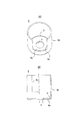
図5(A)は本発明の実施例2に係る筒状ケースを示す斜視図、図5(B)は同筒状ケースの部分縦断面図、図5(C)は同筒状ケースの底面図である。 5A is a perspective view showing a cylindrical case according to a second embodiment of the present invention, FIG. 5B is a partial longitudinal sectional view of the cylindrical case, and FIG. 5C is a bottom surface of the cylindrical case. FIG.
本例の筒状ケース(筒状ヨーク)16の場合も,A相コイル巻線9aの磁路とB相コイル巻線9bの磁路とを兼用するヨークでもあり、プレス成形により、胴板部16bと、シャフト挿通孔hを持ち胴板部16bから折り曲げ形成した底板部16aを有するカップ状である。胴板部16bの開口側の段差にB相アウターヨーク7bbの環状鍔F4の外周縁が接合しており、底板部16aのうち当該底板部16aと胴板部16bとが成す角部寄りに当該角部を巡る3つの長孔Hが環状列設されている。なお、図5(A)中の16cはモールドヨークと一体的に形成した端子台T(図1参照)を外部に臨ませるための切欠き部である。
In the case of the cylindrical case (cylindrical yoke) 16 of this example, it is also a yoke that combines the magnetic path of the A-phase coil winding 9a and the magnetic path of the B-phase coil winding 9b. 16b and a cup shape having a shaft insertion hole h and a
本例においても、ヨーク7aa,7ab,7ba,7bbのいずれもの環状鍔F1〜F4の外周縁が筒状ケース16の内面に接合しているため、各相の高磁気抵抗箇所が2箇所となり、平等化するので、ステップ精度のバラツキを抑制できる。また底板部16aのうち当該底板部16aと胴板部16bとが成す角部寄りに当該角部を巡る3つの長孔Hが環状列設されているため、この角部付近が高磁気抵抗箇所となり、胴板部16b内の磁束が環状鍔F1と重なる底板部16a内へは通り難く、環状鍔F1内を専ら通ることになる。このため、ヨーク7aaは筒状ヨーク16の開口側のヨーク7bbと同等の磁束を通すので、ステップ精度のバラツキを一層抑制できる。
Also in this example, since the outer peripheral edges of any of the ring flanges F 1 to F 4 of the yokes 7aa, 7ab, 7ba, and 7bb are joined to the inner surface of the
図6(A)は本発明の実施例3に係る筒状ケースを示す斜視図、図6(B)は同筒状ケースの部分縦断面図、図6(C)は同筒状ケースの底面図である。
6A is a perspective view showing a cylindrical case according to
本例の筒状ケース(筒状ヨーク)26の場合も,A相コイル巻線9aの磁路とB相コイル巻線9bの磁路とを兼用するヨークでもあり、胴板部26bから折り曲げ形成された3つの突片26aを有する。この突片26aはフレーム3を支持するものである。
The cylindrical case (cylindrical yoke) 26 of this example is also a yoke that serves as both the magnetic path of the A-phase coil winding 9a and the magnetic path of the B-phase coil winding 9b, and is bent from the
本例においても、ヨーク7aa,7ab,7ba,7bbのいずれもの環状鍔F1〜F4の外周縁が筒状ケース26の内面に接合しているため、各相の高磁気抵抗箇所が2箇所となり、平等化するので、ステップ精度のバラツキを抑制できる。3つの突片26aは環状鍔F1の一部に重なるが、筒状ケース26は無底同然であるため、胴板部26b内の磁束がヨーク7aaの環状鍔F1内を必ず通ることになる。このため、ヨーク7aaは筒状ヨーク26の開口側のヨーク7bbと同等の磁束を通すので、ステップ精度のバラツキを一層抑制できる。
Also in this example, since the outer peripheral edges of any of the annular flanges F 1 to F 4 of the yokes 7aa, 7ab, 7ba, and 7bb are joined to the inner surface of the
図7(A)は本発明の実施例4に係る筒状ケースを示す斜視図、図7(B)は同筒状ケースの部分縦断面図、図7(C)は同筒状ケースの底面図である。 7A is a perspective view showing a cylindrical case according to a fourth embodiment of the present invention, FIG. 7B is a partial longitudinal sectional view of the cylindrical case, and FIG. 7C is a bottom surface of the cylindrical case. FIG.
本例の筒状ケース(筒状ヨーク)36の場合も,A相コイル巻線9aの磁路とB相コイル巻線9bの磁路とを兼用するヨークでもあり、胴板部36bのみから成る無底筒状である。なお、フレーム3の支持固定にはモールドヨーク7の極歯間樹脂M1を延長成形した支持部を用いれば好い。
The cylindrical case (cylindrical yoke) 36 of this example is also a yoke that serves as both the magnetic path of the A-phase coil winding 9a and the magnetic path of the B-phase coil winding 9b, and consists only of the
ヨーク7aa,7ab,7ba,7bbのいずれもの環状鍔F1〜F4の外周面が筒状ケース36の内面に接合しているため、各相の高磁気抵抗箇所が2箇所となり、平等化するので、ステップ精度のバラツキを抑制できる。また、筒状ケース36は無底であるため、胴板部36b内の磁束がヨーク7aaの環状鍔F1内を必ず通ることになる。このため、ヨーク7aaは筒状ヨーク36の開口側のヨーク7bbと同等の磁束を通すので、ステップ精度のバラツキを一層抑制できる。
Since the outer peripheral surfaces of the annular flanges F 1 to F 4 of any of the yokes 7aa, 7ab, 7ba, and 7bb are joined to the inner surface of the
1…モータ本体
2…モータシャフト
2a…先端縮径部
2b…抱球穴
3…フレーム
4…軸受
5…マグネット
6,16,26,36…筒状ケース(筒状ヨーク)
6a,16a…底板部
6b,16b,26b,36b…胴板部
6c,16c,26c,36c…切欠き部
7…モールドヨーク
7aa…A相アウターヨーク(第1ヨーク)
7ab…A相インナーヨーク(第2ヨーク)
7ba…B相インナーヨーク(第3ヨーク)
7bb…B相アウターヨーク(第4ヨーク)
9a…A相コイル巻線
9b…B相コイル巻線
10…鋼球
11…ピボット軸受
11a…球受け穴
11b…端面
12…軸受ホルダー
12a…軸受収容孔
12b…フランジ部
13…軸受抜け止め板
13a…板ばね片
26a…突片
h…シャフト挿通孔
F1〜F4…環状鍔
H…長孔
K1〜K4…極歯
M1,M2…極歯絶縁樹脂
S…切り込み部
T…端子台
W1,W2…挟み込み縁辺部
X1,X2,Y1,Y2…案内縁辺部
DESCRIPTION OF
6a, 16a ...
7ab ... A phase inner yoke (second yoke)
7ba ... B phase inner yoke (third yoke)
7bb ... B phase outer yoke (fourth yoke)
9a ... A phase coil winding 9b ... B phase coil winding 10 ...
Claims (3)
前記モールドヨークは第4ヨーク側から前記筒状ヨークの開口を介して突出した樹脂製軸受ホルダーを一体的に有し、前記筒状ヨークは前記胴板部から折り曲げ成形されて第1ヨークの環状鍔の外表面と重なる底板部を有し、前記胴板部と前記底板部とが成す角部の内側に切り込み部が形成されることで、前記底板部に磁束を通り難くし前記第1ヨークに磁束を通すことで、前記第1ヨークと前記第4ヨークとが同等の磁束を通すことを特徴とするステッピングモータ。 Four yokes having a plurality of pole teeth cut and raised at the inner peripheral edge of the annular collar and arranged in an annular row are insert-molded, and the pole teeth of the first yoke and the pole teeth of the second yoke are in a non-contact meshing state. The third yoke and the fourth yoke are connected in a non-contacting state, and the second yoke and the third yoke are connected back to back. A molded yoke, a first coil winding wound between an annular collar of the first yoke and an annular collar of the second yoke, and an annular collar of the third yoke and an annular collar of the fourth yoke. In a stepping motor comprising a wound second coil winding, and a cylindrical yoke having a body plate portion into which the mold yoke is fitted and an outer peripheral edge of each annular flange is joined to an inner surface,
The mold yoke is integrally provided with a resin bearing holder protruding from the fourth yoke side through the opening of the cylindrical yoke, and the cylindrical yoke is bent from the body plate portion to form an annular shape of the first yoke. has a bottom plate portion that overlaps the outer surface of the flange, said at Rukoto the cut portion is formed shell plate portion and the inside of the bottom plate portion and forms a corner portion, the first yoke hardly passes magnetic flux in the bottom plate portion A stepping motor in which the first yoke and the fourth yoke pass an equivalent magnetic flux by passing a magnetic flux through the first yoke .
前記モールドヨークは第4ヨーク側から前記筒状ヨークの開口を介して突出した樹脂製軸受ホルダーを一体的に有し、前記筒状ヨークは前記胴板部から折り曲げ成形されて第1ヨークの環状鍔の外表面と重なる底板部を有し、前記底板部のうち当該底板部と前記胴板部とが成す角部寄りに当該角部を巡る複数の孔が環状列設されることで、前記底板部に磁束を通り難くし前記第1ヨークに磁束を通すことで、前記第1ヨークと前記第4ヨークとが同等の磁束を通すことを特徴とするステッピングモータ。 Four yokes having a plurality of pole teeth cut and raised at the inner peripheral edge of the annular collar and arranged in an annular row are insert-molded, and the pole teeth of the first yoke and the pole teeth of the second yoke are in a non-contact meshing state. The third yoke and the fourth yoke are connected in a non-contacting state, and the second yoke and the third yoke are connected back to back. A molded yoke, a first coil winding wound between an annular collar of the first yoke and an annular collar of the second yoke, and an annular collar of the third yoke and an annular collar of the fourth yoke. In a stepping motor comprising a wound second coil winding, and a cylindrical yoke having a body plate portion into which the mold yoke is fitted and an outer peripheral edge of each annular flange is joined to an inner surface,
The mold yoke is integrally provided with a resin bearing holder protruding from the fourth yoke side through the opening of the cylindrical yoke, and the cylindrical yoke is bent from the body plate portion to form an annular shape of the first yoke. has a bottom plate portion that overlaps the outer surface of the flange, a plurality of holes around the corner to the corner near which forms with the bottom plate and the shell plate portion of the bottom plate portion in Rukoto are cyclic arrayed, wherein A stepping motor characterized in that the first yoke and the fourth yoke pass the same magnetic flux by making it difficult for the magnetic flux to pass through the bottom plate portion and passing the magnetic flux through the first yoke .
前記モールドヨークは第4ヨーク側から前記筒状ヨークの開口を介して突出した樹脂製軸受ホルダーを一体的に有し、前記筒状ヨークは前記胴板部から折り曲げ成形されて第1ヨークの環状鍔の外表面と重なる複数の突片を有し、前記突片には前記シャフトを支持するフレームが支持されることを特徴とするステッピングモータ。 Four yokes having a plurality of pole teeth cut and raised at the inner peripheral edge of the annular collar and arranged in an annular row are insert-molded, and the pole teeth of the first yoke and the pole teeth of the second yoke are in a non-contact meshing state. The third yoke and the fourth yoke are connected in a non-contacting state, and the second yoke and the third yoke are connected back to back. A molded yoke, a first coil winding wound between an annular collar of the first yoke and an annular collar of the second yoke, and an annular collar of the third yoke and an annular collar of the fourth yoke. From a wound second coil winding, a cylindrical yoke having a body plate portion in which the mold yoke is fitted and an outer peripheral edge of each annular flange is joined to an inner surface , a shaft and a magnet in which the shaft is fitted In a stepping motor equipped with an inner rotor
The mold yoke is integrally provided with a resin bearing holder protruding from the fourth yoke side through the opening of the cylindrical yoke, and the cylindrical yoke is bent from the body plate portion to form an annular shape of the first yoke. stepping motor have a plurality of projecting pieces that overlap the outer surface of the flange, the protruding piece, characterized in that the frame for supporting the shaft is supported.
Priority Applications (1)
| Application Number | Priority Date | Filing Date | Title |
|---|---|---|---|
| JP2006087208A JP4901257B2 (en) | 2006-03-28 | 2006-03-28 | Stepping motor |
Applications Claiming Priority (1)
| Application Number | Priority Date | Filing Date | Title |
|---|---|---|---|
| JP2006087208A JP4901257B2 (en) | 2006-03-28 | 2006-03-28 | Stepping motor |
Publications (2)
| Publication Number | Publication Date |
|---|---|
| JP2007267479A JP2007267479A (en) | 2007-10-11 |
| JP4901257B2 true JP4901257B2 (en) | 2012-03-21 |
Family
ID=38639928
Family Applications (1)
| Application Number | Title | Priority Date | Filing Date |
|---|---|---|---|
| JP2006087208A Expired - Fee Related JP4901257B2 (en) | 2006-03-28 | 2006-03-28 | Stepping motor |
Country Status (1)
| Country | Link |
|---|---|
| JP (1) | JP4901257B2 (en) |
Families Citing this family (2)
| Publication number | Priority date | Publication date | Assignee | Title |
|---|---|---|---|---|
| JP4721073B2 (en) | 2008-04-18 | 2011-07-13 | Smc株式会社 | Electromagnetic flow meter |
| KR101108105B1 (en) * | 2008-04-18 | 2012-01-31 | 에스엠씨 가부시키 가이샤 | Electromagnetic flowmeter |
Family Cites Families (5)
| Publication number | Priority date | Publication date | Assignee | Title |
|---|---|---|---|---|
| JPH01113576A (en) * | 1987-10-27 | 1989-05-02 | Toshiba Corp | Guide vane opening and closing device |
| JPH08256461A (en) * | 1995-03-16 | 1996-10-01 | Toshiba Corp | Permanent magnet motor |
| JPH11235002A (en) * | 1998-02-19 | 1999-08-27 | Fuji Elelctrochem Co Ltd | Claw pole stepping motor |
| JP4099643B2 (en) * | 2002-04-05 | 2008-06-11 | セイコーエプソン株式会社 | Stepping motor |
| JP3917549B2 (en) * | 2003-04-24 | 2007-05-23 | ミネベア株式会社 | Stepping motor |
-
2006
- 2006-03-28 JP JP2006087208A patent/JP4901257B2/en not_active Expired - Fee Related
Also Published As
| Publication number | Publication date |
|---|---|
| JP2007267479A (en) | 2007-10-11 |
Similar Documents
| Publication | Publication Date | Title |
|---|---|---|
| JP5109577B2 (en) | Rotating electric machine and insulating member | |
| US6541886B2 (en) | Motor | |
| JP2008187841A (en) | Armature core, armature, motor, and manufacturing method for armature core | |
| JP6629133B2 (en) | Electric motor | |
| JP2002354775A (en) | Stator structure of claw pole stepping motor | |
| JP2005033860A (en) | Structure of claw-pole stepping motor | |
| JP4901257B2 (en) | Stepping motor | |
| JP2015163038A (en) | inner rotor type brushless motor | |
| JP6706483B2 (en) | Geared motor and method of manufacturing geared motor | |
| KR20120092825A (en) | Step motor and method of manufacturing therefor | |
| JP4386909B2 (en) | motor | |
| JP5034070B2 (en) | Stepping motor | |
| JP4798651B2 (en) | Inner rotor type motor | |
| JP2008043139A (en) | Electric motor | |
| JP2015095947A (en) | Pm type stepping motor | |
| JP6157379B2 (en) | Rotating electric machine stator | |
| JP5141861B2 (en) | Stepping motor | |
| JP2008160921A (en) | Stepping motor | |
| JP2007259514A (en) | Rotating electric machine for employing divided stator iron core | |
| JP2007202327A (en) | Capacitor motor | |
| JP4378207B2 (en) | Stepping motor | |
| JP7292887B2 (en) | motor | |
| JP2008067529A (en) | Motor | |
| JP2007143253A (en) | Stepping motor | |
| JP5166835B2 (en) | motor |
Legal Events
| Date | Code | Title | Description |
|---|---|---|---|
| A621 | Written request for application examination |
Free format text: JAPANESE INTERMEDIATE CODE: A621 Effective date: 20080821 |
|
| A977 | Report on retrieval |
Free format text: JAPANESE INTERMEDIATE CODE: A971007 Effective date: 20110209 |
|
| A131 | Notification of reasons for refusal |
Free format text: JAPANESE INTERMEDIATE CODE: A131 Effective date: 20110308 |
|
| A521 | Written amendment |
Free format text: JAPANESE INTERMEDIATE CODE: A523 Effective date: 20110427 |
|
| A711 | Notification of change in applicant |
Free format text: JAPANESE INTERMEDIATE CODE: A711 Effective date: 20110706 |
|
| RD04 | Notification of resignation of power of attorney |
Free format text: JAPANESE INTERMEDIATE CODE: A7424 Effective date: 20110706 |
|
| A521 | Written amendment |
Free format text: JAPANESE INTERMEDIATE CODE: A523 Effective date: 20110715 |
|
| TRDD | Decision of grant or rejection written | ||
| A01 | Written decision to grant a patent or to grant a registration (utility model) |
Free format text: JAPANESE INTERMEDIATE CODE: A01 Effective date: 20111129 |
|
| A01 | Written decision to grant a patent or to grant a registration (utility model) |
Free format text: JAPANESE INTERMEDIATE CODE: A01 |
|
| A61 | First payment of annual fees (during grant procedure) |
Free format text: JAPANESE INTERMEDIATE CODE: A61 Effective date: 20111227 |
|
| R150 | Certificate of patent or registration of utility model |
Free format text: JAPANESE INTERMEDIATE CODE: R150 |
|
| FPAY | Renewal fee payment (event date is renewal date of database) |
Free format text: PAYMENT UNTIL: 20150113 Year of fee payment: 3 |
|
| LAPS | Cancellation because of no payment of annual fees |