JP4900968B2 - Processing control device - Google Patents
Processing control device Download PDFInfo
- Publication number
- JP4900968B2 JP4900968B2 JP2008115666A JP2008115666A JP4900968B2 JP 4900968 B2 JP4900968 B2 JP 4900968B2 JP 2008115666 A JP2008115666 A JP 2008115666A JP 2008115666 A JP2008115666 A JP 2008115666A JP 4900968 B2 JP4900968 B2 JP 4900968B2
- Authority
- JP
- Japan
- Prior art keywords
- tool
- axis
- machining
- control data
- workpiece
- Prior art date
- Legal status (The legal status is an assumption and is not a legal conclusion. Google has not performed a legal analysis and makes no representation as to the accuracy of the status listed.)
- Expired - Fee Related
Links
Images


Description
本発明は、加工機で工具によりワークを加工するときのワークの加工形状に対する工具の食い込みを回避する加工制御装置に関するものである。 The present invention relates to a machining control device for avoiding the biting of a tool with respect to the machining shape of a workpiece when the workpiece is machined with a tool by a machining machine.
一般に工作機械におけるワークの加工においては、事前に加工シミュレーション等を行って加工形状に対し取り過ぎ等の不具合があるか否かを確認し、取り過ぎが確認された場合は該取り過ぎを回避すべく適宜加工プログラム等の修正を行う。このような場合の具体的な技術は、例えば、特許文献1に開示されている。
In general, when machining a workpiece in a machine tool, a machining simulation is performed in advance to check whether there is a problem such as excessive removal of the machining shape, and if excessive removal is confirmed, avoid excessive removal. Modify the machining program etc. as appropriate. A specific technique in such a case is disclosed in
ところで、上述の如く取り過ぎを回避すなわち加工形状に対する工具の食い込みを回避すべく加工プログラム等の修正を行う場合は、一般にオペレータが加工シミュレーションを行い工具の食い込みが回避されるまで加工形状に対する取り残し量や工具の移動方向等の加工条件パラメータや加工形状自体を試行錯誤を繰り返しながら見直す等している。 By the way, when the machining program or the like is modified so as to avoid over-feeding as described above, that is, to avoid biting of the tool into the machining shape, generally, the remaining amount for the machining shape until the operator performs machining simulation and avoids tool biting. The machining condition parameters such as the moving direction of the tool and the machining shape itself are reviewed while repeating trial and error.
しかしながら、このように工具の食い込みを回避すべく作業者が試行錯誤を繰り返していたのでは、作業が極めて煩雑で、加工制御装置における工具の食い込みの回避を効率よく行うことができない。 However, if the operator repeats trial and error in order to avoid the biting of the tool in this way, the work is extremely complicated, and the biting of the tool in the machining control device cannot be efficiently performed.
本発明はこのような事情に鑑みてなされたもので、ワークの加工形状に対する工具の食い込みを効率よく回避することができる加工制御装置を提供することを目的とする。 The present invention has been made in view of such circumstances, and an object thereof is to provide a machining control device capable of efficiently avoiding the biting of a tool with respect to the workpiece machining shape.
上記目的を達成するために、請求項1の加工制御装置に係る発明は、ワークの加工形状を記憶する加工形状記憶手段と、工具がワークを加工する工具位置を複数の軸方向に移動させる加工機を用いてワークを加工形状に加工する際の予め指定された指定工具軌跡を記憶する工具軌跡記憶手段と、工具がワークを加工する際の予め指定された指定工具移動速度を記憶する工具移動速度記憶手段と、最大加速度を加工機の加速の許容限度を示すパラメータとして記憶するパラメータ記憶手段と、指定工具軌跡を、該指定工具軌跡の曲率が小さい部分は大きい間隔で分割し、該指定工具軌跡の曲率が大きくなるに従って小さい間隔で分割して複数の分割軌跡を求める分割軌跡算出手段と、工具移動速度を変えながら工具位置を分割軌跡上で移動させる加工機の駆動部に出力するための、工具位置を指定工具移動速度に従った速度で各分割軌跡上を移動させてワークを加工するときの該分割軌跡上における始点の各軸位置と、該各軸位置から曲率に応じて加速の許容限度を超えないように所定の時間間隔Δtで求めた各軸方向の工具移動速度と、を軸制御データとして求める軸制御データ算出手段と、軸制御データに基づいて工具がワークを加工する際の工具位置を求める工具位置算出手段と、軸制御データに基づいて求められたワークを加工する際の工具位置とワークの加工形状とを比較して該加工形状に対し工具が食い込んだ状態にあるか否かを判断する工具食い込み判断手段と、工具が食い込んだ状態にあると判断されたときに、該食い込んだ状態が回避されるように工具位置を修正する工具位置修正手段と、修正された工具位置に基づいて軸制御データにおける各軸方向の工具移動速度を修正する軸制御データ修正手段と、を備え、所定の時間間隔Δtで求めた各軸方向の工具移動速度が、分割軌跡上の接線方向に工具が移動するよう決められたものであり、駆動部が、軸制御データの所定の時間間隔Δtで求めた時間Tiにおける各軸方向の工具移動速度Viが次の時間Ti+1(=Ti+Δt)までに次の時間Ti+1(=Ti+Δt)における各軸方向の工具移動速度Vi+1になるように各軸方向の工具移動速度を変えるものであることを特徴とする。
To achieve the above object, the invention according to the machining control device of
本発明によれば、上記の手段により加工機の駆動部に出力するための軸制御データに基づいて求められた工具がワークを加工する際の工具位置とワークの加工形状とを比較し、工具が食い込んだ状態にあると判断されたときは、該食い込んだ状態が回避されるように工具位置を修正するとともに、該修正された工具位置に基づいて軸制御データにおける各軸方向の工具移動速度を修正することとしたので、ワークの加工形状に対する工具の食い込みを効率よく回避することができる。 According to the present invention, the tool obtained based on the axis control data to be output to the drive unit of the processing machine by the above means compares the tool position when processing the workpiece with the processing shape of the workpiece, When it is determined that the tool is in the bite state, the tool position is corrected so as to avoid the bite state, and the tool movement speed in each axis direction in the axis control data based on the corrected tool position. Therefore, it is possible to efficiently avoid the biting of the tool with respect to the workpiece machining shape.
請求項2の加工制御装置に係る発明は、ワークの加工形状を記憶する加工形状記憶手段と、工具がワークを加工する工具位置を複数の軸方向に移動させる加工機を用いてワークを加工形状に加工する際の予め指定された指定工具軌跡を記憶する工具軌跡記憶手段と、工具がワークを加工する際の予め指定された指定工具移動速度を記憶する工具移動速度記憶手段と、最大加速度を加工機の加速の許容限度を示すパラメータとして記憶するパラメータ記憶手段と、指定工具軌跡を、該指定工具軌跡の曲率が小さい部分は大きい間隔で分割し、該指定工具軌跡の曲率が大きくなるに従って小さい間隔で分割して複数の分割軌跡を求める分割軌跡算出手段と、工具移動速度を変えながら工具位置を分割軌跡上で移動させる加工機の駆動部に出力するための、工具位置を指定工具移動速度に従った速度で各分割軌跡上を移動させてワークを加工するときの該分割軌跡上における始点の各軸位置と、該各軸位置から曲率に応じて加速の許容限度を超えないように所定の時間間隔Δtで求めた各軸方向の工具移動速度と、を軸制御データとして求める軸制御データ算出手段と、軸制御データに基づいて工具がワークを加工する際の工具位置を求める工具位置算出手段と、軸制御データに基づいて求められたワークを加工する際の工具位置とワークの加工形状とを比較して工具位置が加工形状の内側の領域にあるか外側の領域にあるかを確認し、工具位置が内側の領域にあるときは加工形状に対し工具が食い込んだ状態にあると判断し、工具位置が外側の領域にあるときは工具に食い込みのない状態と判断する工具食い込み判断手段と、工具が食い込んだ状態にあると判断されたときに、工具が加工形状の外側の領域を通過するように食い込んだ状態の工具位置を修正する工具位置修正手段と、修正された工具位置に基づいて軸制御データにおける各軸方向の工具移動速度を修正する軸制御データ修正手段と、を備え、所定の時間間隔Δtで求めた各軸方向の工具移動速度が、分割軌跡上の接線方向に工具が移動するよう決められたものであり、駆動部が、軸制御データの所定の時間間隔Δtで求めた時間Tiにおける各軸方向の工具移動速度Viが次の時間Ti+1(=Ti+Δt)までに次の時間Ti+1(=Ti+Δt)における各軸方向の工具移動速度Vi+1になるように各軸方向の工具移動速度を変えるものであることを特徴とする。
The invention related to the machining control apparatus according to
本発明によれば、上記の手段により加工機の駆動部に出力するための軸制御データに基づいて求められた工具がワークを加工する際の工具位置とワークの加工形状とを比較し、工具が食い込んだ状態にあると判断されたときは、工具が加工形状の外側の領域を通過するように食い込んだ状態の工具位置を修正するとともに、該修正された工具位置に基づいて軸制御データにおける各軸方向の工具移動速度を修正することとしたので、ワークの加工形状に対する工具の食い込みを効率よく回避することができる。 According to the present invention, the tool obtained based on the axis control data to be output to the drive unit of the processing machine by the above means compares the tool position when processing the workpiece with the processing shape of the workpiece, Is determined to be in a state of being bitten, the tool position in a state in which the tool has been bitten so as to pass through the region outside the machining shape is corrected, and in the axis control data based on the corrected tool position Since the tool moving speed in each axial direction is corrected, it is possible to efficiently avoid biting of the tool into the workpiece machining shape.
更に工具位置修正手段は、修正された工具位置のスムージング処理を行い(請求項3)、該スムージング処理は、修正された工具位置の近傍にある食い込みのない工具位置を通りかつ修正された工具位置を近似する近似曲線を生成し、該生成された近似曲線上に修正された工具位置が並ぶように配列し直して工具位置を更に修正する処理とする(請求項4)こととすれば、工具のスムーズな移動が確保され加工時間の短縮も図ることができる。ここで、近似曲線は例えばパラメトリック曲線とすることができる(請求項5)。 Further, the tool position correcting means performs a smoothing process of the corrected tool position (Claim 3), and the smoothing process passes through the tool position without the bite in the vicinity of the corrected tool position and the corrected tool position. Is generated, and the tool position is further corrected by rearranging the corrected tool positions so that the corrected tool positions are aligned on the generated approximate curve. Smooth movement is ensured, and the processing time can be shortened. Here, the approximate curve can be a parametric curve, for example.
なお、上記において「工具位置」とは、工具がワークを加工するときの工具のワークに対する相対的な位置をいい、ワークが移動せず工具のみが移動して加工が行なわれる場合は工具自体の位置を、ワークも移動して加工が行なわれる場合にはワークの工具に対する相対的移動を加味した工具の位置をいう。 In the above, the “tool position” means a relative position of the tool with respect to the workpiece when the tool processes the workpiece. When the workpiece does not move and only the tool moves, the tool itself is moved. In the case where machining is performed by moving the position of the workpiece, it means the position of the tool in consideration of relative movement of the workpiece with respect to the tool.
「工具軌跡」とは、ワーク上を工具位置が移動した軌跡をいう。「工具軌跡」は、工具を移動させてワーク上の工具位置を移動させた軌跡であっても、ワークを移動させてワーク上の工具位置を移動させた軌跡であっても、ワークと工具の双方を移動させながらワーク上の工具位置を移動させた軌跡であってもよい。
「工具移動速度」とは、工具位置がワーク上を移動する速度をいう。また、指定工具移動速度は1のみ指定される場合に限られず、工具軌跡の場所に応じて複数の指定工具移動速度が指定される場合がある。
The “tool locus” refers to a locus on which the tool position moves on the workpiece. The “tool path” is a path in which the tool position on the workpiece is moved by moving the tool, or a path in which the tool position on the workpiece is moved by moving the workpiece. It may be a locus in which the tool position on the workpiece is moved while moving both.
“Tool moving speed” refers to the speed at which the tool position moves on the workpiece. The designated tool movement speed is not limited to the case where only 1 is designated, and a plurality of designated tool movement speeds may be designated according to the location of the tool locus.
「指定工具軌跡の曲率が小さい部分は大きい間隔で分割し、該指定工具軌跡の曲率が大きくなるに従って小さい間隔で分割」とは、工具軌跡の曲率が大きくなるに従って、曲率の小さい部分を分割する大きい間隔よりも小さい間隔で分割することをいう。
「軸制御データ」とは、分割軌跡に従って工具位置を移動させるときに加工機の各軸を制御するためのデータをいう。
「指定工具移動速度に従った速度」とは、指定工具移動速度に近くなるように工具位置を移動させる速度をいい、指定工具移動速度と同じ速度でない場合を含む。
“A part with a small curvature of the designated tool path is divided at a large interval, and is divided at a small interval as the curvature of the designated tool path increases” means that a part with a small curvature is divided as the curvature of the tool path increases. Dividing at smaller intervals than larger intervals.
“Axis control data” refers to data for controlling each axis of the processing machine when the tool position is moved according to the divided trajectory.
The “speed according to the designated tool movement speed” refers to a speed for moving the tool position so as to be close to the designated tool movement speed, and includes a case where the speed is not the same as the designated tool movement speed.
本発明によれば、ワークの加工形状に対する工具の食い込みを効率よく回避することができる。 According to the present invention, it is possible to efficiently avoid the biting of the tool into the work shape of the workpiece.
以下、本発明の実施形態について、図面を用いて説明する。図1は本発明の加工制御装置を含む加工システムの概略構成図である。
本発明の加工システム1は、加工形状を作成するCAD装置2と、加工機を制御する加工制御装置3と、ワークをテーブルに載置して工具でワークを加工する加工機4とからなる。また、CAD装置2と加工制御装置3とはネットワーク5で接続されている。
Hereinafter, embodiments of the present invention will be described with reference to the drawings. FIG. 1 is a schematic configuration diagram of a machining system including a machining control device of the present invention.
The
加工機4は、工具が取り付けられる主軸41と、ワークが載置されるテーブル42と、テーブル42を移動させる送り軸(不図示)と、各軸(主軸、送り軸)を駆動させる駆動部45とを備えている。通常、主軸は切削動力を伝える軸でありZ軸として表わし、テーブル42を移動させる互いに直交する2つの送り軸をX軸とY軸として表す。X軸およびY軸はZ軸と直交している。
The
図2に示すように、駆動部45は、加工制御装置3から各軸を制御する軸制御データAを受取る軸制御データ受信部46と、軸制御データAに従って主軸41であるZ軸の移動信号とテーブル42の送り軸43,44であるX軸とY軸の移動信号を生成する信号生成部47と、主軸を駆動するモータ48aに生成した信号を伝達する主軸アンプ48と、送り軸を駆動するモータ49a,49bに生成した信号を伝達するサーボアンプ49とを備える。なお、図2では回転型のモータが示されているが、リニアモータの場合も同様である。また、サーボアンプ49は、X軸とY軸のそれぞれにあるが、便宜上、図2のブロック図では1つにして示している。
As shown in FIG. 2, the
加工制御装置3は、高性能のマイクロコンピュータとメモリが内蔵されており、メモリに記憶されているプログラムをマイクロコンピュータが実行して、X軸、Y軸、Z軸の各軸を駆動する軸制御データAを生成する。プログラムは加工機4から発生するノイズなどの影響を受けて書き換えられることがないようにROMなどの書き換え不可能なメモリ上に記憶するのが望ましいが、加工機4が発生するノイズの影響を受けないような構成になっていれば、書き換え可能なメモリにプログラムをロードして実行するようにしてもよい。
The machining control device 3 has a built-in high-performance microcomputer and memory, and the microcomputer executes a program stored in the memory to drive each axis of the X axis, the Y axis, and the Z axis. Data A is generated. The program is preferably stored in a non-rewritable memory such as a ROM so that the program is not rewritten due to the influence of noise generated from the
CAD装置2は、汎用コンピュータ(例えばワークステーション等)の補助記憶装置に読み込まれたCADプログラムが実行されることにより実現される。本実施の形態のCAD装置2は、オペレータが入力したワークの加工形状を、三次元のソリッドモデルMのデータとして出力するものである。
The
図3に示すように、加工制御装置3は、各種パラメータ、指定された工具移動速度である指定工具移動速度(以下、指定加工速度という)F、加工形状をオフセットするオフセット値d、ワークを加工する工具を移動させる間隔であるピックフィードPickなどの入力や軸制御データAの修正に際して必要な情報の入力や各種操作を行う操作パネル31と、設定されたパラメータを記憶するパラメータ記憶手段311と、指定加工速度Fを記憶する工具移動速度記憶手段(以下、加工速度記憶手段という)312と、オフセット値dを記憶するオフセット値記憶手段313と、ピックフィードPickを記憶するピックフィード記憶手段314と、CAD装置2で生成されたソリッドモデルMのデータを入力する入力手段32と、ソリッドモデルMのデータを記憶する加工形状記憶手段321(以下、モデルデータ記憶手段321とする)と、ソリッドモデルMをオフセット値d分ほどオフセットした形状(曲面や曲線などで定義される)を生成するオフセット形状生成手段33と、オフセット形状からワークを加工するときに工具位置を移動させる軌跡を指定工具軌跡として求める工具軌跡生成手段34と、指定工具軌跡を記憶する工具軌跡記憶手段341と、指定工具軌跡の曲率に応じて指定工具軌跡を分割した分割軌跡を求める分割軌跡算出手段35と、工具を指定加工速度Fに従う速度で分割軌跡上を移動させるときの各軸の軸制御データAを求める軸制御データ算出手段36と、軸制御データAを記憶する軸制御データ記憶手段361と、軸制御データAを駆動部45に出力する出力手段37と、を備えるとともに、軸制御データ算出手段36により算出された軸制御データAを所要に修正すべく軸制御データ修正システム38を備える。
As shown in FIG. 3, the machining control device 3 processes various parameters, a designated tool movement speed (hereinafter referred to as a designated machining speed) F that is a designated tool movement speed, an offset value d that offsets a machining shape, and a workpiece. An
パラメータには、各加工機に依存する物理特性に関するパラメータ、特に最大加速度、最大加加速度など加速の許容限度を示すパラメータがあり、パラメータに応じて各軸の制御が行われる。また、取り付けられている工具によって最大加速度や最大加加速度などは異なるため、工具に応じてそれぞれパラメータを設定するようにしたものが好ましい。 The parameters include parameters relating to physical characteristics depending on each processing machine, in particular, parameters indicating allowable limits of acceleration such as maximum acceleration and maximum jerk, and each axis is controlled according to the parameters. In addition, since the maximum acceleration, maximum jerk, and the like differ depending on the attached tool, it is preferable to set parameters for each tool.
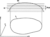
オフセット形状生成手段33は、オフセット値記憶手段313に記憶されたオフセット値d分ほどソリッドモデルMの形状をオフセットした形状を生成する。通常、CAD装置2には仕上げ形状が加工形状として入力され、CAD装置2からは仕上げ形状のソリッドモデルMのデータが出力される。しかし、加工機4に取り付けられた工具で加工を行う際、工具の中心が工具位置となるように各軸を移動させるため、仕上げ形状の表面形状を工具の中心を移動させて加工を行うと、ワークは仕上げ形状より工具半径分余分に切削されることになる。そこで、工具半径分をオフセット値dを用いてソリッドモデルMの表面形状をオフセットした形状を求める。例えば、図4に示すようなソリッドモデルMの表面形状S0を、ボールエンドミルを用いて加工する場合には、表面形状S0を法線方向tにオフセット値d分ほどオフセットした形状S1(以下、オフセット形状という)を求める。
The offset
工具軌跡生成手段34は、オフセット形状S1の上を工具を移動させる指定工具軌跡を生成する。ここでは、等高線加工でワークを加工する場合について説明する。ワークを加工する際には、図5に示すように、オフセット形状S1をXY平面に平行な等高平面Q上で切った交線Lに沿って工具を移動させながらワークを切削し、さらに、一定のピックフィードPickでZ軸方向(上→下)に等高平面Qを移動させながら彫り進めて行く。 The tool locus generating means 34 generates a designated tool locus for moving the tool on the offset shape S1. Here, the case where a workpiece is machined by contour machining will be described. When machining the workpiece, as shown in FIG. 5, the workpiece is cut while moving the tool along an intersection line L obtained by cutting the offset shape S1 on the contour plane Q parallel to the XY plane, Carving is carried out while moving the contour plane Q in the Z-axis direction (up to down) with a constant pick feed Pick.
ピックフィードPickは、工具径やワークの材質に応じて加工に適した値が操作パネル31から入力されてピックフィード記憶手段314に記憶され、XY平面と平行な等高平面Qを指定されたピックフィードPick分動かしながらオフセット形状S1との交線Lを算出して指定工具軌跡を求める。等高平面Qとオフセット形状S1との交線LはBスプラインなどのパラメトリック曲線で表し、パラメトリック曲線を指定工具軌跡Lとしてメモリ(工具軌跡記憶手段341)に記憶する。
In the pick feed Pick, a value suitable for machining is input from the
あるいは、ZX平面、YZ平面に平行な平面とオフセット形状S1との交線を求めて、X軸方向あるいはY軸方向に一定のピックフィードで平面を移動させて彫り進めて行くようにしてもよい。その他、走査加工や面沿い加工、更にはスパイラル加工などの加工方法に応じて指定工具軌跡Lを生成するようにしてもよい。 Alternatively, an intersection line between the plane parallel to the ZX plane and the YZ plane and the offset shape S1 may be obtained, and the plane may be moved by a constant pick feed in the X-axis direction or the Y-axis direction and carved. . In addition, the designated tool path L may be generated according to a machining method such as scanning machining, surface machining, or spiral machining.
分割軌跡算出手段35は、指定工具軌跡Lの曲率に応じて指定工具軌跡Lを分割した分割軌跡を求める。加工機4は、指定された2点間を各軸の速度を制御しながら工具位置を移動させてワークを加工するが、指定工具軌跡Lの曲率が大きい部分では、加工機4の慣性モーメントや剛性などに影響されて、指定工具軌跡Lに沿って工具位置を移動させるのが難しい場合がある。また、加工機4に指定した2点間を結ぶ指定工具軌跡Lが、直線から大きく外れることがない方が好ましい。そこで、指定工具軌跡Lの曲率を求め、図6に示すように、指定工具軌跡Lを曲率が小さいところは大きい間隔で分割し、曲率が大きくなるに従って小さい間隔で分割し、指定工具軌跡L上の点P1,P2,P3,・・・,Pi,Pi+1,・・・で分割した複数の分割軌跡l1,l2,l3,・・・,li,・・・に分ける。
The divided trajectory calculating means 35 obtains a divided trajectory obtained by dividing the designated tool locus L according to the curvature of the designated tool locus L. The
つまり、指定工具軌跡Lの曲率が小さく(曲率が0に近い)略直線になるところでは長い分割軌跡lを加工するようなデータを加工機に指示し、曲率が大きいところは短い分割軌跡lを加工するようなデータを加工機に指示できるように分割する。 That is, when the curvature of the designated tool locus L is small (curvature is close to 0), the processing machine is instructed to process data having a long divided locus l, and when the curvature is large, the short divided locus l is designated. The data to be processed is divided so that it can be instructed to the processing machine.
軸制御データ算出手段36は、分割した各分割軌跡l1,l2,l3,・・・,li,・・・に沿って工具を指定された指定加工速度Fで移動させるときの分割軌跡l上の各軸位置と所定の時間間隔で求めた各軸方向の工具移動速度(以下、軸速度という)の時間変化とを軸制御データAとして求める。軸制御データAには、分割軌跡上の各軸位置として、分割軌跡上の少なくとも1点の各軸の位置を含むものであればよい。例えば、軸制御データAに分割軌跡l上の始点の位置と分割軌跡に沿って移動させるときの各軸の速度変化とが記録されている場合には、始点の位置から各軸を速度変化に従うように各軸を制御することによって、分割軌跡lに沿って工具位置を移動させることができる。 The axis control data calculation means 36 is on the divided locus l when the tool is moved at the designated designated processing speed F along the divided division loci 11, 12, 12, 3,. Axis control data A is obtained as the change in time of each axis position and the tool movement speed in each axis direction (hereinafter referred to as the axis speed) obtained at a predetermined time interval. The axis control data A only needs to include at least one axis position on the division locus as each axis position on the division locus. For example, if the axis control data A records the position of the starting point on the divided locus l and the speed change of each axis when moving along the divided locus, the axis follows the speed change from the position of the starting point. By controlling the respective axes as described above, the tool position can be moved along the division locus l.
例えば、図7に示すような分割軌跡lに沿って、指定された指定加工速度Fでワークを加工するには、工具位置を分割軌跡lの接線方向に指定加工速度Fで移動させることになる。つまり、指定加工速度Fを分割軌跡lの接線ベクトルのX,Y,Zの各成分に分け、X軸をX方向の速度成分で移動させ、Y軸をY方向の速度成分で移動させ、Z軸をZ方向の速度成分で移動させる。図7では、分割軌跡l上の始点の位置P1での各軸の速度成分(軸速度)は(V1x,V1y,V1z)となり、終点の位置P2での各軸の速度成分は(V2x,V2y,V2z)となるので、各軸を位置P1からP2に移動する間に各軸の軸速度をV1x→V2x、V1y→V2y、V1z→V2zに変化させる。また、分割軌跡lに沿うように工具を移動させるには、工具の進行方向が分割軌跡の接線方向に向くように短い時間間隔で各軸の軸速度を変える必要がある。 For example, in order to machine a workpiece at a designated designated machining speed F along a divided locus l as shown in FIG. 7, the tool position is moved at a designated machining speed F in the tangential direction of the divided locus l. . That is, the designated machining speed F is divided into X, Y, and Z components of the tangent vector of the divided locus l, the X axis is moved by the X direction speed component, the Y axis is moved by the Y direction speed component, and Z The axis is moved with the velocity component in the Z direction. In FIG. 7, the velocity components (axial velocity) of each axis at the starting point position P1 on the divided locus l are (V1x, V1y, V1z), and the velocity components of each axis at the ending point position P2 are (V2x, V2y). , V2z), the axis speed of each axis is changed from V1x → V2x, V1y → V2y, and V1z → V2z while each axis is moved from position P1 to P2. Further, in order to move the tool along the divided locus l, it is necessary to change the axial speed of each axis at short time intervals so that the traveling direction of the tool is in the tangential direction of the divided locus.
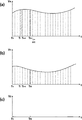
そこで、図8に示すように、各分割軌跡l上を指定加工速度Fで工具を移動させるときの各軸を移動させる軸速度Vx,Vy,Vzの時間変化を表す速度曲線を求める。図8は、Z方向の移動がなくXY平面でのみの移動がある場合を示している。各軸の軸速度をこの速度曲線に従うように制御することにより、工具位置を分割軌跡lに沿って移動させることができる。そこで、軸制御データAに、例えば、各軸の速度曲線を短い一定の時間間隔Δt(セグメントタイム)で分割した点における各軸の軸速度(つまり、一定の時間間隔で求めた各軸の軸速度の時間変化)と、分割軌跡lの開始点を記録する。このような軸制御データAでは、時間T0から時間Tnまでの速度曲線の積分値が時間T0から時間Tnまでに移動した距離となるので、時間Tnにおける各軸の位置は、分割軌跡lの開始点P0に速度曲線のT0〜Tn間の積分値を加えた位置になる。なお、軸制御データ算出手段36は所定の誤差を許容されて軸制御データAを算出する。 Therefore, as shown in FIG. 8, a speed curve representing the temporal change of the axis speeds Vx, Vy, and Vz for moving the respective axes when the tool is moved at the designated machining speed F on each divided trajectory l is obtained. FIG. 8 shows a case where there is no movement in the Z direction and there is a movement only in the XY plane. By controlling the axial speed of each axis so as to follow this speed curve, the tool position can be moved along the division locus l. Therefore, the axis control data A includes, for example, the axis speed of each axis at a point obtained by dividing the speed curve of each axis at a short constant time interval Δt (segment time) (that is, the axis of each axis obtained at a constant time interval). Change in speed) and the start point of the divided trajectory l. In such axis control data A, since the integral value of the velocity curve from time T0 to time Tn is the distance moved from time T0 to time Tn, the position of each axis at time Tn is the start of the divided trajectory l. The position is obtained by adding an integral value between T0 and Tn of the speed curve to the point P0. The axis control data calculation means 36 calculates the axis control data A while allowing a predetermined error.
分割軌跡算出手段35では分割軌跡が直線から大きく外れることがないように指定工具軌跡Lの分割を行うが、加工機4には加速度や加加速度に限界があるため指定された指定加工速度Fを維持したまま、分割軌跡lに沿って工具位置を移動させることができないところがある。そこで、最大加速度や最大加加速度など加速の許容限度を示すパラメータに基づいて、工具位置における分割軌跡lの曲率が大きく、指定加工速度Fで加工を行ったときに分割軌跡lに沿って加工できないと予測される部分では、指定された指定加工速度Fより小さくなるように各軸の軸速度を求める。具体的には、指定された指定加工速度Fで各軸を移動させたときの加速度と加加速度を求めて、パラメータより加工機4の最大加速度や最大加加速度を超えていると判断される部分では、工具位置の移動速度を加工速度記憶手段312に記憶された指定加工速度Fよりも小さい速度にして最大加速度や最大加加速度を超えないように各軸の軸速度を求めて軸制御データAを生成する。
The division trajectory calculation means 35 divides the designated tool trajectory L so that the division trajectory does not greatly deviate from the straight line. However, since the
軸制御データ記憶手段361は、ハードディスクなどの大容量記憶装置上に形成され、軸制御データ算出手段36で生成した軸制御データAを記憶する。また、加工物は、複数の加工工程(荒加工、中仕上加工、仕上加工など)を経て仕上げられるが、軸制御データ記憶手段361には軸制御データAが各加工工程に分けて記憶される。
The axis control
加工機4の信号生成部47は、軸制御データAの速度変化に従って各軸の移動信号を生成して主軸アンプ48,サーボアンプ49に出力する。例えば、図8に示すように、軸制御データAにΔtの間隔で速度を変化させるためのデータが記録され、時間TiのときX軸方向の軸速度がVxiで、時間Ti+1のときX軸方向の軸速度がVx(i+1)であるときには、移動信号は時間Ti〜時間Ti+1の間で、X軸方向の軸速度がVxiからVx(i+1)に変化するような移動信号をサーボアンプ49に出力する。同様に、時間TiのときY軸方向の軸速度がVyiで、時間Ti+1のときY軸方向の軸速度がVy(i+1)であるときには、移動信号は時間Ti〜時間Ti+1の間で、Y軸方向の軸速度がVyiからVy(i+1)に変化するような移動信号をサーボアンプ49に出力する。図8の例では、Z軸方向の軸速度はないので、主軸アンプ48に対する移動信号の出力はない。このように各軸の速度を変えることで、分割軌跡lに沿って工具位置を始点の位置P1から終点の位置P2まで移動させることができる。
The signal generator 47 of the
軸制御データ修正システム38は、ワークの加工形状に対する工具の食い込みを回避すべく軸制御データ算出手段36により算出された軸制御データAにおける軸速度を所要に修正する機能を有している。すなわち、軸制御データAは所定の誤差を許容して算出されるので軸制御データAに基づいて得られる工具位置が分割軌跡から所定の誤差範囲内でずれてしまい、実際に加工を行うと工具が加工形状に対して食い込んで取り過ぎとなることがある。そこで、許容できない工具の食い込みがあるようなときにはオペレータの判断により軸制御データ修正システム38を用いて事前に軸制御データAの修正を行う。この軸制御データ修正システム38は、図9に示すように、工具位置算出手段381と、工具食い込み判断手段382と、工具位置修正手段383と、軸制御データ修正手段384と、を有している。
The axis control
工具位置算出手段381は、軸制御データAに基づいて工具がワークを加工する際の工具位置を算出する。すなわち、軸制御データAには、図8に示すように、Δtの間隔で速度を変化させるデータが記録されているが、各軸の移動量はこの速度曲線を積分した値と一致する。例えば、時間TiのときX軸方向の軸速度がVxiで、時間Ti+1のときX軸方向の軸速度がVx(i+1)であるときには、時間Ti〜Ti+1の間の略台形(斜線部)の面積が時間Ti〜Ti+1の間のX軸方向の工具位置の移動量になる(図8参照)。各軸の工具位置は、各軸制御データAの開始点T0に移動量を加えたところに移動するので、工具位置算出手段381は、各加工工程の先頭の軸制御データAから順番に速度曲線を積分しながら各軸が移動する工具位置をΔtの間隔で求める。図10には工具位置算出手段381により算出された工具位置P12乃至P16におけるX軸方向の工具位置データP12x乃至P16xおよびY軸方向の工具位置データP12y乃至P16yが示されている。
Based on the axis control data A, the tool position calculation means 381 calculates the tool position when the tool processes the workpiece. That is, as shown in FIG. 8, the axis control data A includes data for changing the speed at intervals of Δt, but the movement amount of each axis coincides with the value obtained by integrating this speed curve. For example, when the axial velocity in the X-axis direction is Vxi at time Ti and the axial velocity in the X-axis direction is Vx (i + 1) at time Ti + 1, the area of a substantially trapezoid (shaded portion) between times Ti and Ti + 1. Is the amount of movement of the tool position in the X-axis direction between times Ti and Ti + 1 (see FIG. 8). Since the tool position of each axis moves to the start point T0 of each axis control data A plus the amount of movement, the tool position calculation means 381 performs the speed curve in order from the first axis control data A of each machining step. Is obtained at intervals of Δt. FIG. 10 shows tool position data P12x to P16x in the X-axis direction and tool position data P12y to P16y in the Y-axis direction at the tool positions P12 to P16 calculated by the tool
工具食い込み判断手段382は、工具位置算出手段381により算出された軸制御データAに基づくワークを加工する際の工具位置とワークの加工形状とを比較して加工形状に対し工具が食い込んだ状態にあるか否かを判断する。より詳しくは、工具食い込み判断手段382は、工具位置が加工形状の内側の領域にあるか外側の領域にあるかを確認し、工具位置が内側の領域にあるときは工具が食い込んだ状態にあると判断し、工具位置が外側の領域にあるときは工具に食い込みのない状態と判断する。図11の例示においては、工具食い込み判断手段382は、工具位置P12およびP16は加工形状の外側の領域にあるので食い込みのない状態、工具位置P13乃至P15は加工形状の内側の領域にあるので食い込んだ状態と判断される。なお、加工形状の内側の領域とは、モデルデータ記憶手段321に記憶されている加工形状の輪郭線を境界として工具でワークを加工する際に前記加工形状を取り過ぎとなる側の領域をいい、加工形状の外側の領域とは取り過ぎとならない側の領域をいう。
The tool biting determination means 382 compares the tool position when machining the workpiece based on the axis control data A calculated by the tool position calculation means 381 with the machining shape of the workpiece, so that the tool bites into the machining shape. Judge whether there is. More specifically, the tool biting determination means 382 confirms whether the tool position is in the inner region or the outer region of the machining shape, and the tool is in a state of being bitten when the tool position is in the inner region. When the tool position is in the outer region, it is determined that the tool is not biting. In the example of FIG. 11, the tool biting determination means 382 bites in because there is no biting because the tool positions P12 and P16 are in the outer region of the machining shape, and the tool positions P13 to P15 are in the inner region of the machining shape. It is judged to be in a state. The area inside the machining shape refers to an area on the side where the machining shape is excessively taken when machining a workpiece with a tool, with the outline of the machining shape stored in the model
工具位置修正手段383は、工具位置が食い込んだ状態にあると判断されたときに、該食い込んだ状態が回避されるように工具位置を修正する。より詳しくは、工具位置修正手段383は、工具が加工形状の外側の領域を通過するように食い込んだ状態の工具位置を所定の修正方向に沿って移動させて食い込みのない工具位置に修正する。
When it is determined that the tool position is in a state of being bitten, the tool
すなわち、例えば図12に示す工具位置P13の修正は次のような手順で行う。つまり、工具位置修正手段383は、まず工具位置P13と食い込みのない位置であって工具位置P13の直前の工具位置P12とを直線R1で結び該直線R1の演算式を生成するとともに、モデルデータ記憶手段321からワークの加工形状の輪郭線を定義する関数を読み出し、これら演算式および関数に基づいて直線R1と加工形状の輪郭線との交点P13´の座標値を求める。
That is, for example, the tool position P13 shown in FIG. 12 is corrected in the following procedure. That is, the tool position correcting means 383 first generates an arithmetic expression of the straight line R1 by connecting the tool position P13 and the tool position P12 immediately before the tool position P13 with the straight line R1, and storing the model data. A function that defines the contour line of the machining shape of the workpiece is read from the
そして、図13に示すように、この交点P13´の座標値と工具位置P12の座標値を初期値として2分法による繰り返し計算を行い食い込みのない位置P13Aを求める。この2分法による繰り返し計算は、図14に示すように、工具の端部が加工形状の輪郭線に接するか(図14(a))、または加工形状に食い込むまで行い(図14(b))、工具の端部が輪郭線に接する場合はその工具の位置(工具中心位置)が食い込みのない工具位置P13Aとなる。また、加工形状に食い込むまで繰り返し計算が行われた場合は、工具の端部が食い込む直前の工具の位置(工具中心位置)を食い込みのない工具位置P13Aとなる。 Then, as shown in FIG. 13, by using the coordinate value of the intersection point P13 ′ and the coordinate value of the tool position P12 as initial values, iterative calculation is performed by the bisection method to obtain a position P13A that does not bite. This iterative calculation by the bisection method is performed until the end of the tool touches the contour of the machining shape (FIG. 14A) or bites into the machining shape as shown in FIG. 14 (FIG. 14B). ) When the end portion of the tool is in contact with the contour line, the tool position (tool center position) is the tool position P13A without biting. Further, when the calculation is repeatedly performed until it bites into the machining shape, the tool position (tool center position) immediately before the end of the tool bites becomes the tool position P13A without biting.
このように、図12乃至図14の例示においては、所定の修正方向を、食い込んだ状態の工具位置P13が食い込みのない直前の工具位置P12に直線R1に沿って近づく方向とすることで、修正された工具位置P13Aと該工具位置13Aの直前の食い込みのない工具位置P12とを所定の軌跡で結んだときに該軌跡も加工形状の輪郭線と交差せず、確実に工具の食い込み回避がなされる。つまり、所定の修正方向は、食い込んだ状態の工具位置が食い込みのない工具位置に修正される方向であって、修正された工具位置と該修正された工具位置に対して連続する食い込みのない工具位置とを所定の軌跡で結んだときに該軌跡と加工形状の輪郭線とを交差させない方向に設定される。 As described above, in the examples of FIGS. 12 to 14, the predetermined correction direction is corrected so that the tool position P13 in the bitten state approaches the tool position P12 immediately before the biting in along the straight line R1. When the tool position P13A and the tool position P12 without bite immediately before the tool position 13A are connected with a predetermined path, the path does not intersect with the contour line of the machining shape, and the tool bite can be surely avoided. The In other words, the predetermined correction direction is a direction in which the tool position in the bitten state is corrected to a tool position without biting, and the tool having no bite that is continuous with the corrected tool position and the corrected tool position. When the position is connected by a predetermined locus, the locus is set in a direction that does not intersect the contour of the machining shape.
次いで、工具位置P14を修正する場合も同様に、工具位置P14と該工具位置P14の直前の工具位置であって前記で得られた修正後の工具位置P13A(つまり加工形状に対し食い込みのない位置)とを直線で結び該直線と加工形状の輪郭線との交点を求めるとともに、2分法を活用する等して食い込みのない工具位置(P14A)を求め、更に工具位置P15についても同様の手法で食い込みのない工具位置(P15A)を求める。なお、工具位置の修正は食い込んだ状態の工具位置のうち一部のみを修正することもできる。図15に示すように、食い込んだ状態の工具位置とその各軸の座標値等は表示装置315に表示可能となっており、工具位置の一部のみを修正する場合は、該表示装置315上でオペレータが修正する工具位置を選択して行う。
Next, when the tool position P14 is corrected, similarly, the tool position P14 and the tool position immediately before the tool position P14 and the corrected tool position P13A obtained as described above (that is, a position that does not bite into the machining shape). ) With a straight line, the intersection of the straight line and the contour of the machining shape is obtained, and a tool position (P14A) without biting is obtained by utilizing a bisection method, and the same method is used for the tool position P15. The tool position (P15A) without biting is obtained. Note that the tool position can be corrected by correcting only a part of the tool position in the bitten state. As shown in FIG. 15, the tool position and the coordinate value of each axis of the bited state can be displayed on the
また、工具位置修正手段383は、修正された工具位置のスムージング処理を行う機能も有している。すなわち、図16に示すように、工具位置がP13A乃至P15Aの如く修正された場合、工具の食い込みは回避されるものの修正後はジグザグした工具軌跡となることがあり(図16(a))、工具の移動時間が余計にかかることがあるので、修正された工具位置P13A乃至P15Aの直前および直後(近傍)の食い込みのない工具位置P12,P16を通りかつ工具位置P13A乃至P15Aを近似する近似曲線を生成し(図16(b))、該近似曲線上に修正された工具位置P13A乃至P15Aが含まれるように配列し直して工具位置をP13A´乃至P15A´の如く更に修正する(図16(c))。この近似曲線には例えばBスプライン等のパラメトリック曲線が採用される。 The tool position correcting means 383 also has a function of performing a smoothing process on the corrected tool position. That is, as shown in FIG. 16, when the tool position is corrected as shown in P13A to P15A, the bite of the tool is avoided, but after the correction, a zigzag tool trajectory may be obtained (FIG. 16A). Since the movement time of the tool may be excessive, an approximate curve that approximates the tool positions P13A to P15A through the tool positions P12 and P16 without any bite immediately before (and in the vicinity of) the corrected tool positions P13A to P15A. (FIG. 16 (b)), the tool positions P13A to P15A corrected on the approximate curve are rearranged to further correct the tool positions as P13A 'to P15A' (FIG. 16 ( c)). For example, a parametric curve such as a B-spline is adopted as the approximate curve.
なお、工具位置をP13A´乃至P15A´の如く更に修正した場合に工具位置が食い込んだ状態となるときは、再度工具位置修正手段383が食い込みが回避されるように工具位置を修正するとともに、近似曲線を生成し直して再度修正された工具位置を配列し直す。 In addition, when the tool position is further corrected as in P13A ′ to P15A ′, the tool position correction means 383 corrects the tool position again so that the bite is avoided and approximates the tool position. Regenerate the curve and re-arrange the corrected tool positions.
軸制御データ修正手段384は、修正された各軸の工具位置に基づいて軸制御データAにおける軸速度を修正する。すなわち、例えば図17に示すように、修正後の工具位置P13A´のX軸位置P13Ax´における軸速度V13Ax´は、V13Ax´=(P13Ax´−P12x)/Δtの如く算出され、以下同様にV14Ax´乃至V16x´、V13Ay´乃至V16y´が算出される。そして、軸制御データ修正手段384は軸制御データ記憶手段361に記憶されている修正前の軸速度V13x乃至V16x、V13y乃至V16y(図10)を修正後の軸速度V13Ax´乃至V16x´、V13Ay´乃至V16y´(図17)に書き換える。なお、軸制御データ修正手段384は修正された軸速度に基づいて加速度と加加速度を算出し、該加速度や加加速度が最大加速度や最大加加速度を超えているか否かを確認する。最大加速度等を超えている場合には、軸制御データ修正手段384は最大加速度等を超えないように修正された軸速度の微調整を行う。
The axis control data correction means 384 corrects the axis speed in the axis control data A based on the corrected tool position of each axis. That is, for example, as shown in FIG. 17, the axial speed V13Ax ′ at the corrected X-axis position P13Ax ′ of the tool position P13A ′ is calculated as V13Ax ′ = (P13Ax′−P12x) / Δt, and similarly V14Ax. 'To V16x' and V13Ay 'to V16y' are calculated. Then, the axis control data correcting means 384 corrects the uncorrected shaft speeds V13x to V16x and V13y to V16y (FIG. 10) stored in the axis control data storage means 361 after correcting the shaft speeds V13Ax ′ to V16x ′ and V13Ay ′. To V16y ′ (FIG. 17). The axis control
ここで、本発明の加工システム1でワークを加工する流れについて、図18〜図20のフローチャートを用いて説明する。
加工を行う際、加工機4や用いる工具によって、最大加速度、最大加加速度などに違いがあるため、加工を行う際に一定の加工精度を維持するには、加工機4や用いられる工具に応じて制御方法を調整しなければならない。そこで、まず、加工制御装置3の操作パネル31から、オペレータが最大加速度、最大加加速度などに関する種々のパラメータを設定して、パラメータ記憶手段311に記憶する(S100)。
Here, the flow of machining a workpiece with the
When machining, there is a difference in the maximum acceleration, maximum jerk, etc. depending on the
また、オペレータはCAD装置2を用いて仕上げ形状を加工形状として入力し(S200)、入力された形状に基づいてCAD装置2からソリッドモデルMのデータを出力する(S201)。ソリッドモデルMのデータはネットワーク5を介して加工制御装置3に送信され、加工制御装置3の入力手段32でCAD装置2から送信されたソリッドモデルMを入力してモデルデータ記憶手段321に記憶する(S101)。
The operator inputs the finished shape as a machining shape using the CAD device 2 (S200), and outputs data of the solid model M from the
ワークは荒加工、中仕上げ加工、仕上げ加工などの複数の加工工程を経て加工されるが、これらの加工工程の順番や回数は、加工制御装置3の操作パネル31から入力され、荒加工、中仕上げ加工、仕上げ加工などの各加工工程に用いられる工具や主軸の回転速度に応じた指定加工速度F、オフセット値d、ピックフィードPickが加工速度記憶手段312、パラメータ記憶手段311、ピックフィード記憶手段314、オフセット値記憶手段313に複数記憶される。あるいは、CAD装置2からその加工工程の順番や回数と、各加工工程で使われる指定加工速度F、オフセット値d、ピックフィードPickを受け取るようにしてもよい(S102)。
The workpiece is processed through a plurality of processing steps such as roughing, intermediate finishing, and finishing. The order and the number of times of these processing steps are input from the
加工制御装置3は、オフセット形状生成手段33でソリッドモデルMをオフセット値d分ほどオフセットしたオフセット形状S1を、各加工工程に応じて生成し(S103)、工具軌跡生成手段34でオフセット形状S1の上をピックフィードPick分ずつZ軸方向にXY平面に平行な加工面を移動させながらワークを加工するときの指定工具軌跡Lを生成して工具軌跡記憶手段341に記憶させる(S104)。実際に加工を行う際には、複数の加工工程(荒加工、中仕上加工、仕上加工など)を経て加工が行なわれるため、上述のオフセット形状生成手段33は、各加工工程で用いられる工具に応じたオフセット値を用いてオフセット形状を生成し、工具軌跡生成手段34では、各加工工程で用いられる工具に応じたピックフィードを用いて指定工具軌跡Lを生成する。
The machining control device 3 generates an offset shape S1 obtained by offsetting the solid model M by the offset value d by the offset
次に、分割軌跡算出手段35で、指定工具軌跡Lの曲率に応じて指定工具軌跡Lを分割した分割軌跡lを求める(S105)。さらに、軸制御データ算出手段36で、分割軌跡lに沿って工具位置を指定された指定加工速度Fに従った速度で移動させるための軸制御データAを、各加工工程ごとに生成して軸制御データ記憶手段361に記憶する(S106)。
Next, the divided locus calculation means 35 obtains a divided
次に、生成された軸制御データAを必要に応じて実際に加工を行う前に事前に修正する。
すなわち、まずオペレータが加工制御装置3の操作パネル31から軸制御データ修正システム38の実行開始操作を行う(S301)。
続いて、工具位置算出手段381が指定された軸制御データAを軸制御データ記憶手段361から読み出し、先頭の軸制御データAから順に各軸の移動量を求めて図10に示す如く工具位置を算出する(S302)。
Next, the generated axis control data A is corrected in advance before actual machining as necessary.
That is, first, the operator performs an operation to start execution of the axis control
Subsequently, the axis control data A designated by the tool position calculation means 381 is read from the axis control data storage means 361, and the movement amount of each axis is obtained in order from the head axis control data A to obtain the tool position as shown in FIG. Calculate (S302).
そして、工具食い込み判断手段382は、工具位置算出手段381により算出された工具位置が加工形状の内側の領域にあるか外側の領域にあるかの判断を行う。例えば、図11においては、工具位置P12,P16は加工形状の外側の領域にあるので食い込みのない状態、工具位置P13乃至P15は加工形状の内側の領域にあるので食い込んだ状態と判断される(S303)。 Then, the tool biting determination means 382 determines whether the tool position calculated by the tool position calculation means 381 is in the inner area or the outer area of the machining shape. For example, in FIG. 11, since the tool positions P12 and P16 are in the region outside the machining shape, it is judged that there is no bite, and the tool positions P13 to P15 are judged as being bitten because they are in the region inside the machining shape ( S303).
次いで、工具位置修正手段383は、食い込んだ状態にあると判断された工具位置を食い込みのない適切な位置に修正する。すなわち、例えば図11の工具位置P13を修正する場合においては、図12に示すように、工具位置13と工具位置修正手段383は食い込みのない直前の工具位置P12とを結ぶ直線R1の演算式を生成するとともに、モデルデータ記憶手段321からワークの加工形状の輪郭線を定義する関数を読み出し、これら演算式および関数に基づいて直線R1と加工形状の輪郭線との交点P13´の座標値を求め、更に図13に示す2分法を活用する等して工具位置P13の修正位置P13Aを求める。以下同様に工具位置P14,P15の修正位置P14A,P15Aを求める。なお、図15に示すように、オペレータが表示装置315上で修正する工具位置を適宜選択して食い込んだ工具位置の一部のみを修正することとしてもよい(S304)。
Next, the tool position correcting means 383 corrects the tool position determined to be in a bite state to an appropriate position without bite. That is, for example, when the tool position P13 in FIG. 11 is corrected, as shown in FIG. 12, the tool position correcting means 383 has an equation for a straight line R1 connecting the immediately preceding tool position P12 without biting. A function for defining the contour line of the machining shape of the workpiece is read from the model
続いて、工具位置修正手段383は、修正された工具位置のスムージング処理を行う。すなわち、例えば、図16に示す場合においては、修正された工具位置P13A乃至P15Aの直前および直後(近傍)の工具位置P12,P16を通り工具位置P13A乃至P15Aを近似する近似曲率を生成し、該生成された近似曲線上に工具位置P13A乃至P15Aが含まれるように配列し直して工具位置をP13A´乃至P15A´の如く更に修正する(S305)。なお、工具位置を更に修正した場合に工具位置が食い込んだ状態にあるときは、工具位置修正手段383はステップS304およびステップS305の手順を繰り返す。
Subsequently, the tool
続いて、軸制御データ修正手段384は、修正された各軸方向の工具位置に基づいて軸制御データAにおける軸速度を修正し、軸制御データ記憶手段361に記憶されている修正前の軸速度を修正後の軸速度に書き換える。すなわち、例えば、図17に示すように、軸制御データ修正手段384による軸制御データAの修正によって軸制御データ記憶手段361に記憶されている修正前の軸速度V13x乃至V16x、V13y乃至V16yが修正後の軸速度V13Ax´乃至V16x´、V13Ay´乃至V16y´に書き換えられる。なお、軸制御データ修正手段384は、修正された軸速度に基づいて算出される加速度と加加速度が最大加速度や最大加加速度を超えている場合には、最大加速度等を超えないように修正された軸速度の微調整を行う(S306)。
Subsequently, the axis control
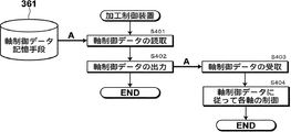
このように、軸制御データAを修正した後は、加工機で加工を行なう。加工制御装置3は、各加工工程ごとに軸制御データ記憶手段361に記憶されている軸制御データAを読み出し(S401)、出力手段37で工具軌跡に沿った順番で分割軌跡l1,l2,l3,・・・,li,・・・の各軸制御データAを加工機4の駆動部45に出力する(S402)。駆動部45の軸制御データ受信部46で軸制御データAを受取り(S403)、信号生成部47で受け取った順に従って軸制御データAから各軸を駆動する信号を生成して主軸アンプ48、サーボアンプ49に出力する(S404)。この軸制御データAには分割軌跡の始点と一定の時間間隔Δtで各軸の速度変化が記録されており、各軸を各分割軌跡lの始点から一定の時間間隔Δtで軸速度を変えることで分割軌跡lに沿って工具位置を移動させる。このようにして全ての加工工程を指定された順番に実行して加工を行う。
As described above, after the axis control data A is corrected, the processing is performed by the processing machine. The machining control device 3 reads the axis control data A stored in the axis control
以上説明したように本実施形態においては、上記の手段により加工機の駆動部に出力するための軸制御データに基づいて求められた工具がワークを加工する際の工具位置とワークの加工形状とを比較し、工具が食い込んだ状態にあると判断されたときは、該食い込んだ状態が回避されるように工具位置を修正するとともに、該工具位置に基づいて軸制御データにおける軸速度を修正することとしたので、ワークの加工形状に対する工具の食い込みを効率よく回避することができる。 As described above, in the present embodiment, the tool position obtained when the tool determined based on the axis control data to be output to the drive unit of the processing machine by the above-mentioned means processes the workpiece, the workpiece shape of the workpiece, When it is determined that the tool is in the bite state, the tool position is corrected so that the bite state is avoided, and the axis speed in the axis control data is corrected based on the tool position. Therefore, it is possible to efficiently avoid the biting of the tool with respect to the machining shape of the workpiece.
また、工具位置を修正する際には、修正された工具位置のスムージング処理、すなわち修正された工具位置の直前および直後の食い込みのない工具位置を通りかつ修正された工具位置を近似する近似曲線を生成し、該生成された近似曲線上に修正された工具位置が含まれるように配列し直して工具位置を更に修正するので、工具のスムーズな移動が確保され加工時間の短縮も図ることができる。 Further, when correcting the tool position, smoothing processing of the corrected tool position, that is, an approximate curve that approximates the corrected tool position passing through the tool position without biting immediately before and after the corrected tool position. Since the tool position is generated and rearranged so that the corrected tool position is included in the generated approximate curve and the tool position is further corrected, smooth movement of the tool is ensured and machining time can be shortened. .
なお、本発明は上述した実施形態に限定されるものではなく、必要に応じて種々の応用実施または変形実施が可能であることは勿論である。
上述の実施の形態では、等高線加工でワークを加工する場合について説明したが、走査線加工や面沿加工においても同様に軸制御データを修正することができる。
In addition, this invention is not limited to embodiment mentioned above, Of course, various application implementation or deformation | transformation implementation is possible as needed.
In the above-described embodiment, the case where the workpiece is machined by the contour line machining has been described. However, the axis control data can be similarly corrected in the scanning line machining and the surface along machining.
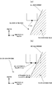
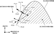
すなわち、面沿い加工においては、図21に示すように、食い込んだ状態の修正されるべき工具位置Pα1と該工具位置Pα1の直前の工具位置であって食い込みのない工具位置Pα2とを結ぶ直線Rα1と加工形状の輪郭線との交点Pα3を求める。そして、交点Pα3を通り加工形状に接する接線Rα2を得るとともに、加工形状の法線方向Rα3を得て、該法線Rα3を工具位置Pα1が含まれるように平行移動して工具位置Pα1の第1の修正方向Rα4を設定し、更にRα4と加工形状の輪郭線との交点Pα1´を求める。そして更に、交点Pα1´を通り加工形状に接する接線Rα5を得るとともに、加工形状の法線方向Rα6を第2の修正方向として得て、該法線方向Rα6に沿ってPα1´から十分に離間した点Pα4(例えば、Pα4はPα1´から工具半径の4倍離間した位置)を設定する。そして、Pα4とPα1´の座標値を初期値として2分法による繰り返し計算を行い、食い込みのない位置Pα1AをRα6上に設定する。 That is, in the in-plane machining, as shown in FIG. 21, a straight line Rα1 that connects the tool position Pα1 to be corrected in the biting state and the tool position Pα2 that is the tool position immediately before the tool position Pα1 and does not bite. And an intersection Pα3 of the contour of the machining shape. Then, a tangent line Rα2 that is in contact with the machining shape through the intersection point Pα3 is obtained, a normal direction Rα3 of the machining shape is obtained, and the normal line Rα3 is translated so that the tool position Pα1 is included, and the first of the tool position Pα1 is obtained. A correction direction Rα4 is set, and an intersection Pα1 ′ between Rα4 and the contour of the machining shape is obtained. Further, a tangent line Rα5 that is in contact with the machining shape through the intersection point Pα1 ′ is obtained, and a normal direction Rα6 of the machining shape is obtained as the second correction direction, and is sufficiently separated from Pα1 ′ along the normal direction Rα6. A point Pα4 (for example, Pα4 is a position separated from Pα1 ′ by four times the tool radius) is set. Then, iterative calculation is performed by the bisection method using the coordinate values of Pα4 and Pα1 ′ as initial values, and a position Pα1A without biting is set on Rα6.
また、走査線加工においては、図22に示すように、食い込んだ状態にある修正されるべき工具位置Pβ1を含んで鉛直方向に延びる修正方向Rβ1を定めるとともに、Rβ1と加工形状の輪郭線との交点Pβ2を求め、更にRβ1に沿ってPβ2から十分に離間した点Pβ3(例えば、Pβ2から工具半径の4倍離間した位置)を設定する。そして、Pβ2とPβ3の座標値を初期値として2分法による繰り返し計算を行い、食い込みのない位置Pβ1AをRβ1上に設定する。 Further, in the scanning line machining, as shown in FIG. 22, a correction direction Rβ1 extending in the vertical direction including the tool position Pβ1 to be corrected is determined, and the Rβ1 and the contour line of the machining shape are defined. An intersection point Pβ2 is obtained, and a point Pβ3 sufficiently separated from Pβ2 along Rβ1 (for example, a position spaced four times the tool radius from Pβ2) is set. Then, iterative calculation is performed by the bisection method with the coordinate values of Pβ2 and Pβ3 as initial values, and a position Pβ1A without biting is set on Rβ1.
図21および図22において上述の如く所定の修正方向を設定することで、食い込んだ状態の工具位置が食い込みのない工具位置に修正されるとともに、修正された工具位置と該修正された工具位置に対し連続する食い込みのない工具位置とを所定の軌跡で結んだときに該軌跡も加工形状の輪郭線と交差せず、確実に工具の食い込み回避がなされる。
上述の実施の形態では、一定の時間間隔で速度変化を記録した軸制御データを用いて制御する場合について説明したが、決められた時間間隔であれば、一定の時間間隔でなくてもよい。
21 and 22, by setting the predetermined correction direction as described above, the tool position in the bitten state is corrected to a tool position without biting, and the corrected tool position and the corrected tool position are changed. On the other hand, when a tool position without continuous biting is connected with a predetermined path, the path does not intersect with the contour line of the machining shape, and the tool biting is surely avoided.
In the above-described embodiment, the case where the control is performed using the axis control data in which the speed change is recorded at a constant time interval has been described. However, as long as the time interval is determined, the time interval may not be constant.
また、軸制御データにはある時間間隔で軸速度を記録する場合について説明したが、速度の変化分を記録するようにしてもよい。
上述の実施の形態では、一定の時間間隔で速度変化を記録した軸制御データを駆動部に出力する場合について説明したが、各軸方向の速度の時間変化を表す数式のデータを軸制御データとして駆動部に出力し、駆動部で受け取った数式に従って軸速度を変化させるようにしてもよい。
Further, although the case where the shaft speed is recorded at certain time intervals has been described in the axis control data, the change in speed may be recorded.
In the above-described embodiment, the case where the axis control data in which the speed change is recorded at a constant time interval is output to the drive unit has been described. However, the mathematical formula data representing the time change of the speed in each axis direction is used as the axis control data. The shaft speed may be changed in accordance with the mathematical formula output to the drive unit and received by the drive unit.
本実施の形態では、加工制御装置にソリッドモデルを入力して、軸制御データを生成する場合について説明したが、CAD装置から出力したソリッドモデルをCAM装置に出力して、CAM装置に軸制御データ生成手段を設けて軸制御データを生成して加工制御装置に出力するようにしてもよい。また、CAM装置で軸制御データを生成する場合には、CAM装置側にさらに軸制御データ修正システムを設けるようにしてもよい。 In the present embodiment, the case where the solid model is input to the machining control apparatus to generate the axis control data has been described. However, the solid model output from the CAD apparatus is output to the CAM apparatus, and the axis control data is output to the CAM apparatus. A generation means may be provided to generate axis control data and output it to the machining control device. When axis control data is generated by the CAM device, an axis control data correction system may be further provided on the CAM device side.
CAM装置は、汎用コンピュータ(例えばワークステーション等)の補助記憶装置に軸制御データを生成する機能を備えたプログラムが読み込まれて実行されることにより実現される。上記機能を備えたプログラムは記録媒体やネットワークを介して配布されてコンピュータにインストールされる。 The CAM device is realized by reading and executing a program having a function of generating axis control data in an auxiliary storage device of a general-purpose computer (for example, a workstation). A program having the above functions is distributed via a recording medium or a network and installed in a computer.
本発明は、加工制御装置においてワークの加工形状に対する工具の食い込みを回避する場合に役立つ。 INDUSTRIAL APPLICABILITY The present invention is useful for avoiding the biting of a tool with respect to the machining shape of a workpiece in a machining control device.
1 加工システム
2 CAD装置
3 加工制御装置
4 加工機
5 ネットワーク
31 操作パネル
32 入力手段
33 オフセット形状生成手段
34 工具軌跡生成手段
35 分割軌跡算出手段
36 軸制御データ算出手段
37 出力手段
38 軸制御データ修正システム
41 主軸
42 テーブル
43,44 送り軸
45 駆動部
46 軸制御データ受信部
47 信号生成部
48 主軸アンプ
48a モータ
49 サーボアンプ
49a,49b モータ
311 パラメータ記憶手段
312 加工速度記憶手段(工具移動速度記憶手段)
313 オフセット値記憶手段
314 ピックフィード記憶手段
315 表示装置
321 加工形状記憶手段(モデルデータ記憶手段)
341 工具軌跡記憶手段
361 軸制御データ記憶手段
381 工具位置算出手段
382 工具食い込み判断手段
383 工具位置修正手段
384 軸制御データ修正手段
M ソリッドモデル
d オフセット値
A 軸制御データ
DESCRIPTION OF
313 Offset value storage means 314 Pick feed storage means 315
341 Tool locus storage means 361 Axis control data storage means 381 Tool position calculation means 382 Tool biting judgment means 383 Tool position correction means 384 Axis control data correction means M Solid model d Offset value A Axis control data
Claims (5)
工具が前記ワークを加工する工具位置を複数の軸方向に移動させる加工機を用いて前記ワークを前記加工形状に加工する際の予め指定された指定工具軌跡を記憶する工具軌跡記憶手段と、
前記工具が前記ワークを加工する際の予め指定された指定工具移動速度を記憶する工具移動速度記憶手段と、
最大加速度を前記加工機の加速の許容限度を示すパラメータとして記憶するパラメータ記憶手段と、
前記指定工具軌跡を、該指定工具軌跡の曲率が小さい部分は大きい間隔で分割し、該指定工具軌跡の曲率が大きくなるに従って小さい間隔で分割して複数の分割軌跡を求める分割軌跡算出手段と、
工具移動速度を変えながら前記工具位置を前記分割軌跡上で移動させる前記加工機の駆動部に出力するための、前記工具位置を前記指定工具移動速度に従った速度で各分割軌跡上を移動させて前記ワークを加工するときの該分割軌跡上における始点の各軸位置と、該各軸位置から前記曲率に応じて前記加速の許容限度を超えないように所定の時間間隔Δtで求めた各軸方向の工具移動速度と、を軸制御データとして求める軸制御データ算出手段と、
前記軸制御データに基づいて前記工具が前記ワークを加工する際の工具位置を求める工具位置算出手段と、
前記軸制御データに基づいて求められた前記ワークを加工する際の工具位置と前記ワークの加工形状とを比較して該加工形状に対し前記工具が食い込んだ状態にあるか否かを判断する工具食い込み判断手段と、
前記工具が食い込んだ状態にあると判断されたときに、該食い込んだ状態が回避されるように前記工具位置を修正する工具位置修正手段と、
前記修正された工具位置に基づいて前記軸制御データにおける各軸方向の工具移動速度を修正する軸制御データ修正手段と、を備え、
前記所定の時間間隔Δtで求めた各軸方向の工具移動速度が、前記分割軌跡上の接線方向に前記工具が移動するよう決められたものであり、
前記駆動部が、前記軸制御データの前記所定の時間間隔Δtで求めた時間Tiにおける前記各軸方向の工具移動速度Viが次の時間Ti+1(=Ti+Δt)までに次の時間Ti+1(=Ti+Δt)における前記各軸方向の工具移動速度Vi+1になるように前記各軸方向の工具移動速度を変えるものであることを特徴とする加工制御装置。 Machining shape storage means for storing the machining shape of the workpiece;
Tool trajectory storage means for storing a designated tool trajectory designated in advance when the workpiece is machined into the machining shape using a processing machine that moves a tool position at which the tool processes the workpiece in a plurality of axial directions;
Tool movement speed storage means for storing a designated tool movement speed designated in advance when the tool processes the workpiece;
Parameter storage means for storing a maximum acceleration as a parameter indicating an allowable limit of acceleration of the processing machine;
A divided trajectory calculating means for dividing the designated tool trajectory at a portion where the curvature of the designated tool trajectory is small at a large interval and dividing the specified tool trajectory at a small interval as the curvature of the designated tool trajectory increases;
The tool position is moved on each divided trajectory at a speed according to the designated tool moving speed for outputting to the drive unit of the processing machine that moves the tool position on the divided trajectory while changing the tool moving speed. Each axis position of the starting point on the division trajectory when machining the workpiece, and each axis determined at a predetermined time interval Δt so as not to exceed the allowable acceleration limit according to the curvature from each axis position Axis control data calculating means for obtaining the tool movement speed in the direction as axis control data,
Tool position calculating means for obtaining a tool position when the tool processes the workpiece based on the axis control data;
A tool for comparing the tool position obtained when machining the workpiece obtained based on the axis control data with the machining shape of the workpiece to determine whether the tool is in a state of biting into the machining shape. A biting judgment means,
Tool position correcting means for correcting the tool position so as to avoid the biting state when it is determined that the tool is in the biting state;
Axis control data correction means for correcting the tool movement speed in each axis direction in the axis control data based on the corrected tool position,
The tool moving speed in each axial direction obtained at the predetermined time interval Δt is determined so that the tool moves in a tangential direction on the divided trajectory,
The next time Ti + 1 (= Ti + Δt) until the next time Ti + 1 (= Ti + Δt) when the tool moving speed Vi in each axis direction at the time Ti obtained by the drive unit at the predetermined time interval Δt of the axis control data. The machining control device is characterized in that the tool moving speed in each axial direction is changed so that the tool moving speed Vi + 1 in each axial direction in FIG .
工具が前記ワークを加工する工具位置を複数の軸方向に移動させる加工機を用いて前記ワークを前記加工形状に加工する際の予め指定された指定工具軌跡を記憶する工具軌跡記憶手段と、
前記工具が前記ワークを加工する際の予め指定された指定工具移動速度を記憶する工具移動速度記憶手段と、
最大加速度を前記加工機の加速の許容限度を示すパラメータとして記憶するパラメータ記憶手段と、
前記指定工具軌跡を、該指定工具軌跡の曲率が小さい部分は大きい間隔で分割し、該指定工具軌跡の曲率が大きくなるに従って小さい間隔で分割して複数の分割軌跡を求める分割軌跡算出手段と、
工具移動速度を変えながら前記工具位置を前記分割軌跡上で移動させる前記加工機の駆動部に出力するための、前記工具位置を前記指定工具移動速度に従った速度で各分割軌跡上を移動させて前記ワークを加工するときの該分割軌跡上における始点の各軸位置と、該各軸位置から前記曲率に応じて前記加速の許容限度を超えないように所定の時間間隔Δtで求めた各軸方向の工具移動速度と、を軸制御データとして求める軸制御データ算出手段と、
前記軸制御データに基づいて前記工具が前記ワークを加工する際の工具位置を求める工具位置算出手段と、
前記軸制御データに基づいて求められた前記ワークを加工する際の工具位置と前記ワークの加工形状とを比較して前記工具位置が前記加工形状の内側の領域にあるか外側の領域にあるかを確認し、前記工具位置が前記内側の領域にあるときは前記加工形状に対し前記工具が食い込んだ状態にあると判断し、前記工具位置が前記外側の領域にあるときは前記工具に食い込みのない状態と判断する工具食い込み判断手段と、
前記工具が食い込んだ状態にあると判断されたときに、前記工具が前記加工形状の外側の領域を通過するように前記食い込んだ状態の工具位置を修正する工具位置修正手段と、
前記修正された工具位置に基づいて前記軸制御データにおける各軸方向の工具移動速度を修正する軸制御データ修正手段と、を備え、
前記所定の時間間隔Δtで求めた各軸方向の工具移動速度が、前記分割軌跡上の接線方向に前記工具が移動するよう決められたものであり、
前記駆動部が、前記軸制御データの前記所定の時間間隔Δtで求めた時間Tiにおける前記各軸方向の工具移動速度Viが次の時間Ti+1(=Ti+Δt)までに次の時間Ti+1(=Ti+Δt)における前記各軸方向の工具移動速度Vi+1になるように前記各軸方向の工具移動速度を変えるものであることを特徴とする加工制御装置。 Machining shape storage means for storing the machining shape of the workpiece;
Tool trajectory storage means for storing a designated tool trajectory designated in advance when the workpiece is machined into the machining shape using a processing machine that moves a tool position at which the tool processes the workpiece in a plurality of axial directions;
Tool movement speed storage means for storing a designated tool movement speed designated in advance when the tool processes the workpiece;
Parameter storage means for storing a maximum acceleration as a parameter indicating an allowable limit of acceleration of the processing machine;
A divided trajectory calculating means for dividing the designated tool trajectory at a portion where the curvature of the designated tool trajectory is small at a large interval and dividing the specified tool trajectory at a small interval as the curvature of the designated tool trajectory increases;
The tool position is moved on each divided trajectory at a speed according to the designated tool moving speed for outputting to the drive unit of the processing machine that moves the tool position on the divided trajectory while changing the tool moving speed. Each axis position of the starting point on the division trajectory when machining the workpiece, and each axis determined at a predetermined time interval Δt so as not to exceed the allowable acceleration limit according to the curvature from each axis position Axis control data calculating means for obtaining the tool movement speed in the direction as axis control data,
Tool position calculating means for obtaining a tool position when the tool processes the workpiece based on the axis control data;
Whether the tool position is in the inner region or the outer region of the machining shape by comparing the tool position obtained when machining the workpiece obtained based on the axis control data with the machining shape of the workpiece. When the tool position is in the inner area, it is determined that the tool is in a state of biting into the machining shape, and when the tool position is in the outer area, the tool is bite. Tool biting judgment means for judging that there is no state,
Tool position correcting means for correcting the tool position of the bited state so that the tool passes through a region outside the machining shape when it is determined that the tool is in a bited state;
Axis control data correction means for correcting the tool movement speed in each axis direction in the axis control data based on the corrected tool position,
The tool moving speed in each axial direction obtained at the predetermined time interval Δt is determined so that the tool moves in a tangential direction on the divided trajectory,
The next time Ti + 1 (= Ti + Δt) until the next time Ti + 1 (= Ti + Δt) when the tool moving speed Vi in each axis direction at the time Ti obtained by the drive unit at the predetermined time interval Δt of the axis control data. The machining control device is characterized in that the tool moving speed in each axial direction is changed so that the tool moving speed Vi + 1 in each axial direction in FIG .
Priority Applications (1)
| Application Number | Priority Date | Filing Date | Title |
|---|---|---|---|
| JP2008115666A JP4900968B2 (en) | 2008-04-25 | 2008-04-25 | Processing control device |
Applications Claiming Priority (1)
| Application Number | Priority Date | Filing Date | Title |
|---|---|---|---|
| JP2008115666A JP4900968B2 (en) | 2008-04-25 | 2008-04-25 | Processing control device |
Publications (2)
| Publication Number | Publication Date |
|---|---|
| JP2009266000A JP2009266000A (en) | 2009-11-12 |
| JP4900968B2 true JP4900968B2 (en) | 2012-03-21 |
Family
ID=41391767
Family Applications (1)
| Application Number | Title | Priority Date | Filing Date |
|---|---|---|---|
| JP2008115666A Expired - Fee Related JP4900968B2 (en) | 2008-04-25 | 2008-04-25 | Processing control device |
Country Status (1)
| Country | Link |
|---|---|
| JP (1) | JP4900968B2 (en) |
Cited By (1)
| Publication number | Priority date | Publication date | Assignee | Title |
|---|---|---|---|---|
| WO2017110236A1 (en) * | 2015-12-24 | 2017-06-29 | 三菱電機株式会社 | Tool path modification device and tool path modification method |
Families Citing this family (3)
| Publication number | Priority date | Publication date | Assignee | Title |
|---|---|---|---|---|
| JP6063161B2 (en) | 2012-07-20 | 2017-01-18 | 株式会社ミツトヨ | Shape measuring apparatus and method for controlling shape measuring apparatus |
| DE102014223434A1 (en) * | 2014-11-17 | 2016-05-19 | P & L Gmbh & Co. Kg | Method for machining a workpiece by means of a cutting tool on an NC-controlled machine tool |
| WO2019130412A1 (en) * | 2017-12-26 | 2019-07-04 | 三菱電機株式会社 | Machining program modification device and machining program modification method |
Family Cites Families (6)
| Publication number | Priority date | Publication date | Assignee | Title |
|---|---|---|---|---|
| JP2595572B2 (en) * | 1987-10-30 | 1997-04-02 | ソニー株式会社 | Offset data creation method |
| JPH09160624A (en) * | 1995-12-06 | 1997-06-20 | Toyota Motor Corp | Tool path determining method |
| JPH1128641A (en) * | 1997-07-08 | 1999-02-02 | Asahi Glass Co Ltd | Plate machining device |
| JPH11282517A (en) * | 1998-03-12 | 1999-10-15 | Internatl Business Mach Corp <Ibm> | Pulse control method using multiplier and system therefor |
| JP2004171268A (en) * | 2002-11-20 | 2004-06-17 | Yaskawa Electric Corp | Command generator for numerical controller |
| JP2006163665A (en) * | 2004-12-06 | 2006-06-22 | Toshiba Corp | Numerical control information verification system for numerically controlled working machine and method |
-
2008
- 2008-04-25 JP JP2008115666A patent/JP4900968B2/en not_active Expired - Fee Related
Cited By (3)
| Publication number | Priority date | Publication date | Assignee | Title |
|---|---|---|---|---|
| WO2017110236A1 (en) * | 2015-12-24 | 2017-06-29 | 三菱電機株式会社 | Tool path modification device and tool path modification method |
| JP6157781B1 (en) * | 2015-12-24 | 2017-07-05 | 三菱電機株式会社 | Tool path correcting device and tool path correcting method |
| US10599126B2 (en) | 2015-12-24 | 2020-03-24 | Mitsubishi Electric Corporation | Tool-path correcting apparatus and tool-path correcting method |
Also Published As
| Publication number | Publication date |
|---|---|
| JP2009266000A (en) | 2009-11-12 |
Similar Documents
| Publication | Publication Date | Title |
|---|---|---|
| JP4847428B2 (en) | Machining simulation apparatus and program thereof | |
| JP5417392B2 (en) | Numerical controller | |
| JP6133995B2 (en) | Tool path evaluation method, tool path generation method, and tool path generation device | |
| JP6450732B2 (en) | Numerical controller | |
| WO2016067392A1 (en) | Tool path generation method and machine tool | |
| JP5737970B2 (en) | Machine tool control system | |
| JP6646027B2 (en) | Post-processor device, machining program generation method, CNC machining system, and machining program generation program | |
| JP4796936B2 (en) | Processing control device | |
| JP4802170B2 (en) | Machining time calculation device and program thereof | |
| JP4900968B2 (en) | Processing control device | |
| JP6811908B1 (en) | Numerical control device, machine learning device and numerical control method | |
| JP2001125613A (en) | Numerical control simulation device | |
| JP5013482B2 (en) | Processing simulation equipment | |
| JP2935713B2 (en) | Numerical control unit | |
| WO2015037150A1 (en) | Tool path generating method and tool path generating device | |
| WO2010134532A1 (en) | Numerical control device | |
| JP4982170B2 (en) | Machining control device and machining control program | |
| JP6823032B2 (en) | Program modifier | |
| JPH09190211A (en) | System for controlling route of numerically controlled device | |
| JP7355951B1 (en) | Control device and computer readable recording medium | |
| JP2021026602A (en) | Movement path generation device | |
| WO2023058243A9 (en) | Control device and computer-readable recording medium storing program | |
| WO2024042618A1 (en) | Control device and computer-readable recording medium | |
| WO2021230237A1 (en) | Processing path creation device | |
| CN118043750A (en) | Control device and computer-readable recording medium having program recorded thereon |
Legal Events
| Date | Code | Title | Description |
|---|---|---|---|
| A621 | Written request for application examination |
Free format text: JAPANESE INTERMEDIATE CODE: A621 Effective date: 20100916 |
|
| A977 | Report on retrieval |
Free format text: JAPANESE INTERMEDIATE CODE: A971007 Effective date: 20110726 |
|
| A131 | Notification of reasons for refusal |
Free format text: JAPANESE INTERMEDIATE CODE: A131 Effective date: 20110729 |
|
| A521 | Request for written amendment filed |
Free format text: JAPANESE INTERMEDIATE CODE: A523 Effective date: 20110905 |
|
| TRDD | Decision of grant or rejection written | ||
| A01 | Written decision to grant a patent or to grant a registration (utility model) |
Free format text: JAPANESE INTERMEDIATE CODE: A01 Effective date: 20111222 |
|
| A01 | Written decision to grant a patent or to grant a registration (utility model) |
Free format text: JAPANESE INTERMEDIATE CODE: A01 |
|
| A61 | First payment of annual fees (during grant procedure) |
Free format text: JAPANESE INTERMEDIATE CODE: A61 Effective date: 20111226 |
|
| R150 | Certificate of patent or registration of utility model |
Ref document number: 4900968 Country of ref document: JP Free format text: JAPANESE INTERMEDIATE CODE: R150 Free format text: JAPANESE INTERMEDIATE CODE: R150 |
|
| FPAY | Renewal fee payment (event date is renewal date of database) |
Free format text: PAYMENT UNTIL: 20150113 Year of fee payment: 3 |
|
| R250 | Receipt of annual fees |
Free format text: JAPANESE INTERMEDIATE CODE: R250 |
|
| R250 | Receipt of annual fees |
Free format text: JAPANESE INTERMEDIATE CODE: R250 |
|
| R250 | Receipt of annual fees |
Free format text: JAPANESE INTERMEDIATE CODE: R250 |
|
| R250 | Receipt of annual fees |
Free format text: JAPANESE INTERMEDIATE CODE: R250 |
|
| R250 | Receipt of annual fees |
Free format text: JAPANESE INTERMEDIATE CODE: R250 |
|
| R250 | Receipt of annual fees |
Free format text: JAPANESE INTERMEDIATE CODE: R250 |
|
| R250 | Receipt of annual fees |
Free format text: JAPANESE INTERMEDIATE CODE: R250 |
|
| R250 | Receipt of annual fees |
Free format text: JAPANESE INTERMEDIATE CODE: R250 |
|
| LAPS | Cancellation because of no payment of annual fees |