JP4888529B2 - Humidifier and air conditioner equipped with humidifier - Google Patents

Humidifier and air conditioner equipped with humidifier Download PDF

Info

Publication number
JP4888529B2
JP4888529B2 JP2009156840A JP2009156840A JP4888529B2 JP 4888529 B2 JP4888529 B2 JP 4888529B2 JP 2009156840 A JP2009156840 A JP 2009156840A JP 2009156840 A JP2009156840 A JP 2009156840A JP 4888529 B2 JP4888529 B2 JP 4888529B2
Authority
JP
Japan
Prior art keywords
air
adsorption
regeneration
adsorbent
path
Prior art date
Legal status (The legal status is an assumption and is not a legal conclusion. Google has not performed a legal analysis and makes no representation as to the accuracy of the status listed.)
Active
Application number
JP2009156840A
Other languages
Japanese (ja)
Other versions
JP2011012876A (en
Inventor
真理 齋藤
毅 内田
怜司 森岡
Current Assignee (The listed assignees may be inaccurate. Google has not performed a legal analysis and makes no representation or warranty as to the accuracy of the list.)
Mitsubishi Electric Corp
Original Assignee
Mitsubishi Electric Corp
Priority date (The priority date is an assumption and is not a legal conclusion. Google has not performed a legal analysis and makes no representation as to the accuracy of the date listed.)
Filing date
Publication date
Application filed by Mitsubishi Electric Corp filed Critical Mitsubishi Electric Corp
Priority to JP2009156840A priority Critical patent/JP4888529B2/en
Publication of JP2011012876A publication Critical patent/JP2011012876A/en
Application granted granted Critical
Publication of JP4888529B2 publication Critical patent/JP4888529B2/en
Active legal-status Critical Current
Anticipated expiration legal-status Critical

Links

Images

Description

本発明は、空気中の水分を吸着させた吸着材に加熱した空気を当て、吸着材から水分を脱着させて空気中に含ませるようにした加湿装置、およびその加湿装置を備えた空気調和機に関するものである。   The present invention relates to a humidifying device in which heated air is applied to an adsorbent that has adsorbed moisture in the air so that the moisture is desorbed from the adsorbent and included in the air, and an air conditioner equipped with the humidifier It is about.

従来技術として、固定された吸着材、前記吸着材を通過するように設けられた空気流通路、前記空気流通路の前記吸着材の上流側に設けられたヒータ、前記空気流通路の前記吸着材の下流側に設けられた送風装置、前記空気流通路の前記送風装置の下流側に設けられ室内吸気用通路と室外排気用通路とを切り換えるダンパとからなり、吸着時にはヒータをオフにして空気を室外に排出し、再生時にはヒータをオンにして空気を室内に吸気する技術が知られている。(例えば、特許文献1参照) As a conventional technique, a fixed adsorbent, an air flow passage provided to pass through the adsorbent, a heater provided upstream of the adsorbent in the air flow passage, and the adsorbent in the air flow passage A blower provided downstream of the blower, and a damper provided on the downstream side of the blower for switching the air flow passage between the indoor intake passage and the outdoor exhaust passage. A technique is known in which the air is discharged to the outside and the heater is turned on to regenerate the air into the room during regeneration. (For example, see Patent Document 1)

特許3559421号公報(0037欄−0045欄、図3)Japanese Patent No. 3559421 (columns 0037-0045, FIG. 3)

従来技術では、吸着材の同じ領域に吸着用空気と、再生用空気とを交互に通過させる必要があるとともに、吸着時にはヒータをオフ、再生時にはヒータをオンに切り換える必要があり、温度が安定するまでの時間がかかるため、連続的にしかも十分な加湿量を得ることができないという課題があった。
また、吸着時及び再生時の空気流の方向が同一であり、水分が吸着される面と水分が脱着される面とが互いに逆の面であるため、吸脱着効率が低下するという課題があった。
In the prior art, it is necessary to alternately pass the adsorption air and the regeneration air through the same area of the adsorbent, and it is necessary to turn off the heater during adsorption and to turn on the heater during regeneration, so that the temperature is stabilized. Therefore, there is a problem that a sufficient amount of humidification cannot be obtained continuously.
In addition, the direction of air flow during adsorption and regeneration is the same, and the surface on which moisture is adsorbed and the surface on which moisture is desorbed are opposite to each other. It was.

この発明は、上述のような課題を解決するためになされたものであり、気密性が高く空気漏洩の少ない風路を構成し、1台の加湿ユニットにて室内へ連続的に加湿空気を供給し、吸着工程と再生工程が対向流となる加湿器を得ることを目的としている。
また同時に、上記の風路構成にて、風速分布を一様とし、ヒータの熱伝導を向上させた加湿装置及び加湿機能を有する空気調和機を得ることを目的としている。
The present invention has been made to solve the above-described problems, and constitutes an air passage with high airtightness and less air leakage, and continuously supplies humidified air to the room with a single humidifying unit. The object is to obtain a humidifier in which the adsorption process and the regeneration process are counterflow.
At the same time, an object of the present invention is to obtain a humidifier and an air conditioner having a humidifying function in which the wind velocity distribution is uniform and the heat conduction of the heater is improved with the above-described air path configuration.

本発明の加湿装置は、吸脱着機構部の内部を2つの領域に分割するように水分吸着材を固定して設置し、互いに逆方向に前記水分吸着材を通過するように再生空気通気路とを吸着空気通気路とを設けるとともに、前記2つの領域それぞれに設けられた第1の風路切換ダンパ及び第2の風路切換ダンパが、前記再生空気通気路と前記吸着空気通気路とを切り換えることにより、前記水分吸着材のうち前記再生空気通気路が通過する再生部分と、前記吸着空気通気路が通過する吸着部分とを切り換える構成としたものである。 The humidifying device of the present invention has a moisture adsorbing material fixed and installed so as to divide the inside of the adsorption / desorption mechanism part into two regions, and the regenerative air ventilation path and the regenerative air vent so as to pass through the moisture adsorbing material in opposite directions. And the first air path switching damper and the second air path switching damper provided in each of the two regions switch between the regeneration air ventilation path and the adsorption air ventilation path. Accordingly, the moisture adsorbing material is configured to switch between a regeneration portion through which the regeneration air ventilation path passes and an adsorption portion through which the adsorption air ventilation path passes.

また、前記2つの領域のうち前記再生空気通気路の吸入される領域内に、前記再生空気通気路を流れる前記高温空気の向きと同方向に設けられた複数の通気口を備え、前記通気口は、前記第1の風路切換ダンパにより開閉されるようにしたものである。 A plurality of ventilation holes provided in the same direction as the direction of the high-temperature air flowing through the regeneration air ventilation path in the area where the regeneration air ventilation path is sucked out of the two areas; Is opened and closed by the first air path switching damper.

この発明により、気密性が高く空気漏洩の少ない風路が構成され、1台の加湿ユニットにて室内へ連続的に加湿空気を供給し、吸着工程と再生工程が対向流となる加湿器を得ることができる。また、風速分布が一様となり、これにより、ヒータの熱伝導率が向上した加湿装置及び加湿機能を有する空気調和機が得られる効果がある。 According to the present invention, an air passage having high airtightness and less air leakage is configured, and humidified air is continuously supplied into a room by a single humidifying unit to obtain a humidifier in which an adsorption process and a regeneration process are counterflows. be able to. In addition, the wind speed distribution is uniform, thereby providing an effect of obtaining a humidifier with improved heater thermal conductivity and an air conditioner having a humidification function.

この発明の実施の形態1における、加湿装置の概略構成図。The schematic block diagram of the humidification apparatus in Embodiment 1 of this invention. この発明の実施の形態1における、吸脱着機構部44の風路構成の詳細図。The detailed drawing of the air path structure of the adsorption / desorption mechanism part 44 in Embodiment 1 of this invention. この発明の実施の形態1における、風路仕切板と風路切換ダンパの接触部横観図。The contact part side view of an air-path partition plate and an air-path switching damper in Embodiment 1 of this invention. この発明の実施の形態1における、水分吸着材周辺風路の各部品の平面図。The top view of each component of the water | moisture-content adsorbent surrounding air path in Embodiment 1 of this invention. この発明の実施の形態1における、送風手段の一例であるシロッコファンの各部位の名称を示す正面断面図。Front sectional drawing which shows the name of each site | part of the sirocco fan which is an example of the ventilation means in Embodiment 1 of this invention. この発明の実施の形態1における、送風手段における順方向部分を示す正面断面図。Front sectional drawing which shows the forward direction part in the ventilation means in Embodiment 1 of this invention. この発明の実施の形態2における、加湿機能を有する空気調和機における室外側の概略構成図。The schematic block diagram of the outdoor side in the air conditioner which has a humidification function in Embodiment 2 of this invention. この発明の実施の形態3における、加湿機能を有する空気調和機における加湿装置の概略設置図。The schematic installation figure of the humidification apparatus in the air conditioner which has a humidification function in Embodiment 3 of this invention. この発明の実施の形態4における、加湿機能を有する空気調和機における加湿装置の概略設置図。The schematic installation figure of the humidification apparatus in the air conditioner which has a humidification function in Embodiment 4 of this invention.

実施の形態1.
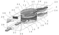
図1は、本発明の実施の形態1における加湿装置の概略構成図である。加湿ユニット1は、水分の吸着及び脱着を行う吸脱着機構部44と、吸着空気送風手段3と、再生空気送風手段4と、再生空気加熱手段5とから構成されている。吸着空気送風手段3は、例えばシロッコファンからなり、吸脱着機構部44の後述する吸着空気排気口18に接続された吸着空気排気路51に配設されている。また、再生空気送風手段4は、例えばシロッコファンからなり、吸脱着機構部44の後述する再生空気排気口19に接続された再生空気排気路52に配設されている。
Embodiment 1 FIG.
FIG. 1 is a schematic configuration diagram of a humidifying device according to Embodiment 1 of the present invention. The humidifying unit 1 includes an adsorption / desorption mechanism 44 that adsorbs and desorbs moisture, an adsorption air blowing unit 3, a regeneration air blowing unit 4, and a regeneration air heating unit 5. The adsorbed air blowing means 3 is composed of, for example, a sirocco fan, and is disposed in an adsorbed air exhaust path 51 connected to an adsorbed air exhaust port 18 (to be described later) of the adsorption / desorption mechanism 44. The regeneration air blowing means 4 is made of, for example, a sirocco fan, and is disposed in a regeneration air exhaust path 52 connected to a regeneration air exhaust port 19 (to be described later) of the suction / desorption mechanism 44.

吸脱着機構部44は、全体に円柱形状をしており、その内部に空気中の水分を吸着するとともに通気性を有する吸着材2と、風路切換部とが設置されている。吸着材2は、扁平な円柱形状をしており、吸脱着機構部44のほぼ中央部に固定され、吸脱着機構部44を上下2つの領域に分割するように設置される。吸着材2としては、たとえばゼオライト、シリカゲル、活性炭等を、多孔質基材に塗布あるいは表面処理あるいは含浸されたものが使用される。 The adsorption / desorption mechanism 44 has a cylindrical shape as a whole, and has an adsorbent 2 that adsorbs moisture in the air and has air permeability, and an air path switching unit. The adsorbent 2 has a flat cylindrical shape, is fixed to substantially the center of the adsorption / desorption mechanism portion 44, and is installed so as to divide the adsorption / desorption mechanism portion 44 into two upper and lower regions. As the adsorbent 2, for example, a material obtained by applying, surface treatment or impregnation to a porous substrate with zeolite, silica gel, activated carbon or the like is used.

再生空気加熱手段5は、コイル状に巻かれたヒータ線からなり、再生空気吸気路50内を流れる空気を満遍なく加熱できるように、その吸気路断面を覆うように設置されている。この再生空気吸気路50は、一端が後述する吸脱着機構部44の再生空気吸気口17に接続され、吸脱着機構部44を介して再生空気排気路52に接続されることにより、加湿ユニット1内に一連の再生空気通気路を形成している。 The regenerative air heating means 5 is composed of a heater wire wound in a coil shape, and is installed so as to cover the cross section of the intake passage so that the air flowing in the regenerative air intake passage 50 can be evenly heated. One end of the regeneration air intake path 50 is connected to the regeneration air intake port 17 of the adsorption / desorption mechanism section 44 described later, and is connected to the regeneration air exhaust path 52 via the adsorption / desorption mechanism section 44, so that the humidifying unit 1. A series of regeneration air vents are formed in the interior.

同様に、吸着空気吸気路49の一端が後述する吸脱着機構部44の吸着空気吸気口16に接続され、吸脱着機構部44を介して吸着空気排気路51に接続されることにより、加湿ユニット1内に一連の吸着空気通気路を形成している。 Similarly, one end of the adsorbed air intake passage 49 is connected to an adsorbed air intake port 16 of an adsorption / desorption mechanism portion 44 described later, and is connected to the adsorbed air exhaust passage 51 via the adsorption / desorption mechanism portion 44, whereby the humidification unit. A series of adsorbed air ventilation paths are formed in 1.

次に、吸脱着機構部44の詳細について説明する。
図2は、吸脱着機構部44の詳細図であり、各部品を分解してわかりやすく示してあるが、各部品は実際には重合状態に組み合わされている。
Next, details of the adsorption / desorption mechanism 44 will be described.
FIG. 2 is a detailed view of the adsorption / desorption mechanism 44, and each component is disassembled and shown in an easy-to-understand manner, but each component is actually combined in a superposed state.

風路切換部は、吸着材2を挟んで上部風路切換部と下部風路切換部からなる。上部風路切換部は、第1の風路仕切枠6と,第2の風路仕切枠7と,これら風路仕切枠の間に介在させた第1の風路切換ダンパ14とから構成されている。同様に、下部風路切換部は、第3の風路仕切枠8と,第4の風路仕切枠9と、これら風路仕切枠の間に介在させた第2の風路切換ダンパ15とから構成されている。 The air path switching unit includes an upper air path switching unit and a lower air path switching unit with the adsorbent 2 interposed therebetween. The upper air path switching unit is composed of a first air path partition frame 6, a second air path partition frame 7, and a first air path switching damper 14 interposed between these air path partition frames. ing. Similarly, the lower air path switching unit includes a third air path partition frame 8, a fourth air path partition frame 9, and a second air path switching damper 15 interposed between these air path partition frames. It is composed of

上部風路切換部において、第1の風路仕切枠6と、第2の風路仕切枠7は、円筒状の枠板と、この枠板の中心をとおり、その内側を2分割するよう両端が枠板に固定された第1の風路仕切板10と第2の風路仕切板11とを有している。これら風路仕切枠6、7は、各風路仕切板10、11が直交するように対向して配置され、第2の風路仕切枠7を吸着材2の上面に第2の風路仕切板11が当接するよう重合している。従って、上部風路切換部を上から見ると、吸着材2の上面が第2の風路仕切枠7によって2つの領域に均等に分割されるとともに、吸着材2の上方空間は一対の風路仕切枠6、7によって4つの領域に均等に分割された状態になる。
そして、第1の風路仕切枠6の枠板に、第1の風路仕切板10を挟んで対向する位置に1/4円周の幅を有する再生空気吸気口17及び吸着空気排気口18が形成され、また、各風路仕切枠6、7の各風路仕切板10、11の両側面のほぼ中央部にその全長にわたり水平に所定高さの第1の風路仕切板のリブ25、第2の風路仕切板のリブ26を突設している。
In the upper air path switching unit, the first air path partition frame 6 and the second air path partition frame 7 pass through a cylindrical frame plate and the center of the frame plate, and both ends are divided into two. Has a first air passage partition plate 10 and a second air passage partition plate 11 fixed to the frame plate. These air channel partition frames 6 and 7 are arranged so as to face each other so that the air channel partition plates 10 and 11 are orthogonal to each other, and the second air channel partition frame 7 is arranged on the upper surface of the adsorbent 2 with the second air channel partition frame. It superposes | stacks so that the board 11 may contact | abut. Therefore, when the upper air path switching unit is viewed from above, the upper surface of the adsorbent 2 is equally divided into two regions by the second air path partition frame 7, and the upper space of the adsorbent 2 is a pair of air paths. The partition frames 6 and 7 are equally divided into four regions.
The regeneration air intake port 17 and the adsorption air exhaust port 18 having a width of ¼ circumference at positions facing the frame plate of the first air channel partition frame 6 with the first air channel partition plate 10 interposed therebetween. In addition, the rib 25 of the first air passage partition plate having a predetermined height horizontally at almost the center of both side surfaces of the air passage partition plates 10 and 11 of the air passage partition frames 6 and 7. The ribs 26 of the second air passage partition plate are projected.

第1の風路切換ダンパ14は、円形状の板体であり、第1と第2の風路切換枠6、7の間に少なくとも回転可能となるように挟持され、中心部を挟んで中心角を直角とする一対の扇形をした開口部141、142が対称位置に形成され、残りに扇形部分をそのまま閉塞部143、144としている。そして、第1の風路切換ダンパ14の上面に各開口部の縁部に沿って平面視でL字形状をした端板29を垂直に形成するとともに、その下面に閉塞部143、144の縁部に沿って平面視でL字形状をした端板30を垂直に形成している。この各端板29、30は各外側面間に各風路仕切板10、11が垂直に挿入できるよう中心線と平行にずらせることで所定の間隙を形成している。また、各端板29,30は各風路仕切板10、11のリブ25、26の下面ないしは上面にほぼ接する高さに形成されている。 The first air path switching damper 14 is a circular plate, and is sandwiched between the first and second air path switching frames 6 and 7 so as to be at least rotatable, with the center portion interposed therebetween. A pair of fan-shaped openings 141 and 142 whose corners are right angles are formed at symmetrical positions, and the remaining fan-shaped portions are used as blocking portions 143 and 144 as they are. Then, an L-shaped end plate 29 is formed vertically on the upper surface of the first air path switching damper 14 along the edge of each opening, and the edges of the blocking portions 143 and 144 are formed on the lower surface thereof. An end plate 30 having an L shape in plan view is formed vertically along the portion. The end plates 29 and 30 form predetermined gaps by being shifted parallel to the center line so that the air passage partition plates 10 and 11 can be inserted vertically between the outer side surfaces. The end plates 29 and 30 are formed at a height substantially in contact with the lower surface or the upper surface of the ribs 25 and 26 of the air passage partition plates 10 and 11.

一方、下部風路切換部は、図2に示すように、上部風路切換部と同様の構成であり、第3の風路仕切板12を有する第3の風路仕切枠8と、第2の風路切換ダンパ15と、第4の風路仕切板13を有する第4の風路仕切枠9とが順次重合して配置されている。そして、第3の風路仕切枠8の第3の風路仕切板12が吸着材2の下面に接するよう第2の風路仕切枠7の第2の風路仕切板11と同一方向になるよう配置される。但し、第2の風路切換ダンパ15については、上部風路切換部のものとは表裏を逆にし、1/4円周だけ回転させた状態で一対の風路仕切枠8、9の間に重合される。すなわち、一対の扇形をした開口部151、152と、一対の閉塞部153、154が上部風路切換部の第1の風路切換ダンパ14の閉塞部と開口部とそれぞれ対向するような関係となっている。そして、第4の風路仕切枠9の側面には、第1の風路仕切枠6の再生空気吸気口17及び吸着空気排気口18と対応する位置に吸着空気吸気口16と、再生空気排気口19がそれぞれ形成される。 On the other hand, as shown in FIG. 2, the lower air path switching unit has the same configuration as the upper air path switching unit, and includes a third air path partition frame 8 having a third air path partition plate 12, The air path switching damper 15 and the fourth air path partition frame 9 having the fourth air path partition plate 13 are sequentially superposed and arranged. And it becomes the same direction as the 2nd air path partition plate 11 of the 2nd air path partition frame 7 so that the 3rd air path partition plate 12 of the 3rd air path partition frame 8 may contact the lower surface of the adsorbent 2. Arranged so that. However, the second air path switching damper 15 is reversed between the upper air path switching section and rotated by a quarter circumference between the pair of air path partition frames 8 and 9. Polymerized. That is, the relationship is such that the pair of fan-shaped openings 151 and 152 and the pair of blocking sections 153 and 154 face the closing section and the opening section of the first air path switching damper 14 of the upper air path switching section. It has become. Then, on the side surface of the fourth air passage partition frame 9, the adsorbed air intake port 16 and the regenerative air exhaust at positions corresponding to the regeneration air intake port 17 and the adsorbed air exhaust port 18 of the first air passage partition frame 6. Each mouth 19 is formed.

なお、各風路切換ダンパ14、15は、少なくとも90度の範囲で往復回転させるために、例えば周面の一部にそれぞれ歯車部を一体形成し、この各歯車部に噛み合う扇形の歯車を1個のステッピングモーターにて回転するようにする。また、各風路仕切枠6、7、8、9及び各風路切換ダンパ14、15は、空気の漏れを極力減らすため、全体を予め円筒状の筐体内に挿入し、筐体内にて所定の風路を形成するようにしてもよく、あるいは、第1と第4の風路仕切枠6、9の上面あるいは下面を塞ぐとともに一方の風路仕切枠で風路切換ダンパの周面を覆うようにして、各構成部品を重合状態に組み合わせるようにしてもよい。後者の場合、吸着材2の外周面から空気が漏れないよう非通気性の材料で覆っておく等の対応が必要である。 Each of the air path switching dampers 14 and 15 has, for example, a gear portion integrally formed on a part of the peripheral surface and a fan-shaped gear that meshes with each gear portion in order to reciprocately rotate within a range of at least 90 degrees. Rotate with a single stepping motor. Further, the air path partition frames 6, 7, 8, 9 and the air path switching dampers 14 and 15 are all inserted in advance into a cylindrical casing in order to reduce air leakage as much as possible, and predetermined inside the casing. Alternatively, the upper and lower surfaces of the first and fourth air passage partition frames 6 and 9 may be closed and the peripheral surface of the air passage switching damper may be covered with one air passage partition frame. In this way, each component may be combined in a polymerized state. In the latter case, it is necessary to take measures such as covering with an air-impermeable material so that air does not leak from the outer peripheral surface of the adsorbent 2.

次に、吸脱着機構部44と、再生空気通気路及び吸着空気通気路との接続構成について説明する。
再生空気吸気路50はいわゆるダクト構造であり、第1の風路仕切枠6の再生空気吸気口17に接続され、その内側面が第1の風路仕切枠6の中心を通る延長線上に、外側面が内側面と平行かつ第1の風路仕切枠6の接線の延長線上にあって、その開口部から吸気口まで同一断面積を有する風路を形成している。また、吸着空気吸気路49も再生空気吸気路50と同様な構造であり、第4の風路仕切枠9の吸着空気吸気口16に接続される。一方、吸着空気排気路51も同様にダクト構造を有し、第1の風路仕切枠6の吸着空気排気口18に接続され、その内側面が第1の風路仕切枠6の中心を通る延長線上に、外側面が内側面と平行かつ第1の風路仕切枠6の接線の延長線上にあって、吸着空気排気口18から開口部まで同一断面積を有する風路を形成している。また、再生空気排気路52も吸着空気排気路51と同様の構造であって第4の風路仕切枠9の再生空気排気口19に接続される。
Next, a connection configuration between the adsorption / desorption mechanism 44 and the regeneration air ventilation path and the adsorption air ventilation path will be described.
The regeneration air intake passage 50 has a so-called duct structure, is connected to the regeneration air intake port 17 of the first air passage partition frame 6, and an inner surface thereof extends on an extension line passing through the center of the first air passage partition frame 6. The outer side surface is parallel to the inner side surface and is on the extension of the tangent line of the first air passage partition frame 6, and forms an air passage having the same cross-sectional area from the opening to the intake port. The adsorption air intake passage 49 has the same structure as the regeneration air intake passage 50 and is connected to the adsorption air intake port 16 of the fourth air passage partition frame 9. On the other hand, the adsorption air exhaust passage 51 has a duct structure in the same manner, and is connected to the adsorption air exhaust port 18 of the first air passage partition frame 6, and the inner side surface passes through the center of the first air passage partition frame 6. On the extension line, an air passage having the same cross-sectional area from the adsorbed air exhaust port 18 to the opening is formed with the outer surface parallel to the inner surface and on the tangent line of the first air passage partition frame 6. . The regeneration air exhaust path 52 has the same structure as the adsorption air exhaust path 51 and is connected to the regeneration air exhaust port 19 of the fourth air path partition frame 9.

次に、各空気排気路51、52と各空気送風手段3、4との関係について説明する。
図5は、送風手段の一例としてのシロッコファンの正面断面図を示している。図5において、羽47は反時計回りに回転して、正面の空気吸い込み口(図示せず)から空気を吸い込み、図5右上部分の吐出口から空気を排出する。
Next, the relationship between the air exhaust paths 51 and 52 and the air blowing means 3 and 4 will be described.
FIG. 5 shows a front sectional view of a sirocco fan as an example of the air blowing means. In FIG. 5, the wing 47 rotates counterclockwise, sucks air from a front air suction port (not shown), and discharges air from the discharge port in the upper right part of FIG.

そして、このシロッコファンは、図6に示すように、羽47の回転方向と風路内の空気が流れる方向とが少なくとも一致するように各空気排気路51、52に設置される。このとき、各空気排気路51、52の幅とシロッコファンの半径とが一致するように設置することが望ましく、吐出口の向きは図6の<A>に示すように各空気排気路51,52と平行に設置してもよいし、図6の<B>に示すように各空気排気路51、52と直交するように設置してもよい。 And this sirocco fan is installed in each air exhaust path 51 and 52 so that the rotation direction of the wing | blade 47 and the direction through which the air in an airflow flows may correspond at least as shown in FIG. At this time, it is desirable to install the air exhaust passages 51 and 52 so that the width of the air exhaust passages 51 and 52 coincide with the radius of the sirocco fan, and the direction of the discharge port is as shown in <A> of FIG. 52 may be installed in parallel with each other, or may be installed so as to be orthogonal to the air exhaust paths 51 and 52 as shown in <B> of FIG.

なお、吸着材2から排出された空気流を各送風手段3、4に吸入させる際には、図5に示す送風手段の舌部46に空気流を当てないことが望ましい。空気流を舌部46に当てないためにも、また、空気流を各送風手段3、4の順方向部分48に吸入させるためにも、第1の風路仕切板10は吸着空気排気路51と平行になるように設置する。 When the air flow discharged from the adsorbent 2 is sucked into the air blowing means 3 and 4, it is desirable not to apply the air flow to the tongue 46 of the air blowing means shown in FIG. In order to prevent the air flow from being applied to the tongue portion 46 and also to suck the air flow into the forward direction portion 48 of each blowing means 3, 4, the first air passage partition plate 10 is provided with the adsorbed air exhaust passage 51. Install so that it is parallel to.

以上のように構成された加湿装置について、以下その動作について説明する。図4は、吸脱着機構部44の動作状態を各部品ごとに示す平面図である。 The operation of the humidifier configured as described above will be described below. FIG. 4 is a plan view showing the operation state of the adsorption / desorption mechanism 44 for each part.

まず、吸着材2における水分の吸着動作について説明する。各風路切換ダンパ14、15の位置が図4の<A>のとき、吸着空気送風手段3が駆動すると、水分を含む室外空気20は、吸着空気吸気路49を通り、第4の風路仕切枠9の吸着空気吸気口16から吸い込まれ、第4の風路仕切板13によって仕切られた一方の領域9aに流入する。この領域9aの上面の第2の風路切換ダンパ15は、閉塞部154と開口部151とが対応位置しているため、室外空気はその開口部151から第3の風路仕切枠8の一方の領域8bに流入する。 First, the moisture adsorption operation in the adsorbent 2 will be described. When the position of each of the air path switching dampers 14 and 15 is <A> in FIG. 4, when the adsorbed air blowing means 3 is driven, the outdoor air 20 containing moisture passes through the adsorbed air intake path 49 and passes through the fourth air path. The air is sucked from the adsorbed air inlet 16 of the partition frame 9 and flows into one region 9 a partitioned by the fourth air passage partition plate 13. In the second air path switching damper 15 on the upper surface of the region 9a, the closed portion 154 and the opening portion 151 are located at the corresponding positions. Therefore, the outdoor air passes from the opening portion 151 to one of the third air path partition frames 8. Into the region 8b.

第3の風路仕切枠8は第3の風路仕切板12によって枠内が半円に仕切られ、第2の仕切枠7は第2の風路仕切板11によって枠内が半円に仕切られているため、それら2つの仕切枠に挟まれている吸着材2も各仕切板により同様に分割されている。このため、第3の風路仕切枠8の領域8bに流入した室外空気は、吸着材2の一方の領域2bを透過して第2の風路仕切枠7の一方の領域7bに流入する。このとき室外空気に含まれた水分が吸着材2によって吸着されて乾燥空気となる。 The third airway partition frame 8 is partitioned into a semicircle by the third airway partition plate 12, and the second partition frame 7 is partitioned into a semicircle by the second airway partition plate 11. Therefore, the adsorbent 2 sandwiched between the two partition frames is similarly divided by each partition plate. For this reason, outdoor air that has flowed into the region 8 b of the third air passage partition frame 8 passes through one region 2 b of the adsorbent 2 and flows into one region 7 b of the second air passage partition frame 7. At this time, moisture contained in the outdoor air is adsorbed by the adsorbent 2 to become dry air.

水分が除かれた乾燥空気は、第2の風路仕切枠7の領域7bに対応する第1の風路切換ダンパ14の開口部142から第1の風路仕切枠6の第1の風路仕切板10によって仕切られた片方の領域6bへ流入し、その後吸着空気排気口18より流出し、吸着空気送風手段3を経て室外へ排気される。 The dry air from which moisture has been removed passes through the opening 142 of the first air path switching damper 14 corresponding to the region 7 b of the second air path partition frame 7 and the first air path of the first air path partition frame 6. It flows into one area 6 b partitioned by the partition plate 10, then flows out from the adsorption air exhaust port 18, and is exhausted to the outside through the adsorption air blowing means 3.

このようにして、吸着材2の片方の領域2bにおける吸着動作を所定時間が継続することにより、吸着材2の領域2bの部分は、十分に湿潤状態となる。なお、運転開始当初は吸着材2に加湿に必要な水分がまだ吸着されてなく、加湿動作を行うことができないので、再生空気通気風路側の再生空気送風手段4の運転は停止していてもよい。 In this manner, the adsorption operation in one area 2b of the adsorbent 2 is continued for a predetermined time, so that the area 2b of the adsorbent 2 is sufficiently wet. At the beginning of the operation, moisture necessary for humidification is not yet adsorbed on the adsorbent 2, and the humidification operation cannot be performed. Therefore, even if the operation of the regeneration air blowing means 4 on the regeneration air ventilation air passage side is stopped. Good.

次に、吸着材2の再生動作について説明する。
まず、図4に示されるように、中心軸45を回転軸として、第1の風路切換ダンパ14と第2の風路切換ダンパ15とを、ステッピングモーターを駆動し、互いに逆方向に90°回転させ、ダンパ位置を<A>から<B>へと切り換える。
Next, the regeneration operation of the adsorbent 2 will be described.
First, as shown in FIG. 4, the first wind path switching damper 14 and the second wind path switching damper 15 are driven by 90 ° in opposite directions with the central axis 45 as a rotation axis by driving the stepping motor. Rotate to change the damper position from <A> to <B>.

再生空気通気風路側の再生空気送風手段4を駆動すると、室外空気が再生空気吸気路50から吸い込まれ、途中再生空気加熱手段5の加熱によって昇温された高温空気22は、第1の風路仕切枠6の再生空気吸気口17より吸い込まれ、第1の風路仕切板10によって仕切られた領域6aへ流入する。この領域6aの底面に対応位置する第1の風路切換ダンパ14はその領域の左半分を閉塞部144とし、右半分を開口部141としているから、流入空気は開口部141から第2の風路仕切枠7内の第2の風路仕切板11で仕切られた右半分の領域7bへ流入する。 When the regeneration air blowing means 4 on the regeneration air ventilation air passage side is driven, the outdoor air is sucked from the regeneration air intake passage 50, and the high temperature air 22 heated by the regeneration air heating means 5 is heated in the first air passage. The air is sucked from the regeneration air intake port 17 of the partition frame 6 and flows into the region 6 a partitioned by the first air path partition plate 10. Since the first air path switching damper 14 positioned corresponding to the bottom surface of the region 6a has the left half of the region as the blocking portion 144 and the right half as the opening 141, the inflowing air flows from the opening 141 to the second wind. It flows into the right half area 7b partitioned by the second air path partition plate 11 in the path partition frame 7.

第2の風路仕切枠7は第2の風路仕切板11によって半円に仕切られ、第3の風路仕切枠8は第3の風路仕切板12によって同様に半円に仕切られているから、2つの風路仕切枠7、8に挟まれている吸着材2の表面も同様に2つの領域に分割されている。このため、第2の風路仕切枠7の片方の領域7bに流入した高温低湿空気は、吸着動作のときとは逆に吸着材2の領域2bを上面から下面に向かって透過し、第3の風路仕切枠8の領域8bに流入する。吸着材2の領域2bは、先の吸着動作で水分が吸着されて湿潤状態となっているので、空気22は、この湿潤状態となった領域2bを通過する時に、領域2bから水分を脱着して加湿された空気となる。 The second airway partition frame 7 is divided into semicircles by the second airway partition plate 11, and the third airway partition frame 8 is similarly divided into semicircles by the third airway partition plate 12. Therefore, the surface of the adsorbent 2 sandwiched between the two air passage partition frames 7 and 8 is similarly divided into two regions. For this reason, the high-temperature and low-humidity air that has flowed into one region 7b of the second air passage partition frame 7 permeates the region 2b of the adsorbent 2 from the upper surface toward the lower surface, contrary to the case of the adsorption operation. It flows into the area 8b of the air channel partition frame 8. Since the region 2b of the adsorbent 2 is in a wet state because moisture has been adsorbed by the previous adsorption operation, the air 22 desorbs moisture from the region 2b when passing through the wet region 2b. And become humidified air.

加湿された空気は、第3の風路仕切枠8の領域8bから、この領域に対応する第2の風路切換ダンパ15の開口部152より第4の風路仕切板13の領域9bへ流入し、その後再生空気排気口19より再生空気24として流出し、再生空気送風手段4を経て室内へ搬送されて、室内を加湿する。 The humidified air flows from the area 8b of the third air path partition frame 8 into the area 9b of the fourth air path partition plate 13 through the opening 152 of the second air path switching damper 15 corresponding to this area. Then, it flows out from the regeneration air exhaust port 19 as regeneration air 24, is conveyed to the room through the regeneration air blowing means 4, and humidifies the room.

この動作中に、他方の吸着空気送風手段3を同時に駆動すると、図4の<B>に示すように、室外空気20が吸着空気吸気路49を経て第4の風路仕切枠9の吸着空気吸気口16から第4の風路仕切板13で仕切られた片方の領域9aに流入する。この流入空気21はかかる領域9aに対応する第2の風路切換ダンパ15の開口部151から第3の風路仕切枠8の片方の領域8aに流入し、この領域8aに対応する吸着材2の左半分の領域2aを下から上に透過し、このときその流入する室外空気に含まれる水分が吸着材2の領域2aに吸着されることになる。水分が除かれた乾燥空気は、第2の風路仕切枠7の仕切板で仕切った片方の領域7aに流入し、この領域7aに対応する第1の風路切換ダンパ14の開口部142から第1の風路仕切枠6の片方の領域6bに流入する。その後、乾燥空気は第1の風路仕切枠6の再生空気排気口19から排出され、吸着空気送風手段3を経て室外に排気される。 If the other adsorbed air blowing means 3 is simultaneously driven during this operation, the outdoor air 20 passes through the adsorbed air intake channel 49 and the adsorbed air of the fourth air channel partition frame 9 as shown in <B> of FIG. The air flows from the intake port 16 into one region 9a partitioned by the fourth air passage partition plate 13. This inflow air 21 flows into one area 8a of the third air path partition frame 8 from the opening 151 of the second air path switching damper 15 corresponding to the area 9a, and the adsorbent 2 corresponding to this area 8a. In this case, the moisture contained in the outdoor air flowing into the left half region 2a is adsorbed by the region 2a of the adsorbent 2. The dry air from which moisture has been removed flows into one area 7a partitioned by the partition plate of the second air path partition frame 7, and from the opening 142 of the first air path switching damper 14 corresponding to this area 7a. It flows into one area 6 b of the first air passage partition frame 6. Thereafter, the dry air is discharged from the regeneration air exhaust port 19 of the first air passage partition frame 6, and is exhausted outside through the adsorption air blowing means 3.

すなわち、二つの風路切換ダンパ14、15が図4<A>の状態のときには、吸着材2の領域2bに水分の吸着が行なわれるとともに領域2aは水分の脱着が同時に行われ、二つの風路切換ダンパ14、15が図4<B>の状態のときには、吸着材2の領域2aに水分の吸着が領域2bは水分の脱着が同時に行われることになる。 That is, when the two air path switching dampers 14 and 15 are in the state shown in FIG. 4 <A>, moisture is adsorbed in the region 2b of the adsorbent 2, and moisture is desorbed simultaneously in the region 2a. When the path switching dampers 14 and 15 are in the state shown in FIG. 4 <B>, moisture is adsorbed in the region 2a of the adsorbent 2 and moisture is desorbed in the region 2b.

このようにして、第1の風路切換ダンパ14及び第2の風路切換ダンパ15を90度の範囲で往復回転させることにより、吸脱着機構部44内部の風路が切り換わり、吸着材2のうち再生空気路が通過する再生部分と、吸着空気路が通過する吸着部分とが切り換えられることになり、加湿空気を連続的に生成することが可能になる。
ところで、二つの風路切換ダンパ14、15は、風路切換え動作時において、その上下両面に設けた各端板29、30の外側面を各風路仕切枠6〜9の各仕切板10〜13にそれぞれ当接させて、風路を切り換えると同時に風路からの空気の漏れを防止している。図3に図2矢印A方向からみた状態を示す。
In this way, by rotating the first air path switching damper 14 and the second air path switching damper 15 in the range of 90 degrees, the air path inside the adsorption / desorption mechanism 44 is switched, and the adsorbent 2 Among these, the regeneration portion through which the regeneration air passage passes and the adsorption portion through which the adsorption air passage passes are switched, and humidified air can be continuously generated.
By the way, the two air path switching dampers 14 and 15 are arranged so that the outer surfaces of the end plates 29 and 30 provided on the upper and lower surfaces of the air path switching dampers 14 and 15 respectively correspond to the partition plates 10 to 10 of the air path partition frames 6 to 9. The air paths are switched at the same time to prevent air leakage from the air paths. FIG. 3 shows a state seen from the direction of arrow A in FIG.

すなわち、第1の風路仕切枠6の第1の風路仕切板10に設けられたリブ25の設置位置と、第1の風路切換ダンパ14の上面に設けられた端板29の高さがほぼ一致しているので、第1の風路仕切板10の左右いずれかの側面およびリブ25に、第1の風路切換ダンパ14の端板29の外側面と端面が当接して気密状態が保持されている。 That is, the installation position of the rib 25 provided on the first air passage partition plate 10 of the first air passage partition frame 6 and the height of the end plate 29 provided on the upper surface of the first air passage switching damper 14. Are substantially coincident with each other, so that the outer surface and the end surface of the end plate 29 of the first air path switching damper 14 are in contact with either the left or right side surface of the first air path partition plate 10 and the ribs 25 and are in an airtight state. Is held.

同様に、第2の風路仕切枠7の第2の風路仕切板11に設けられたリブ26の設置位置と、第1の風路切換ダンパ14の下面に設けられた端板30の高さがほぼ一致しているので、第2の風路仕切板11の左右いずれかの側面およびリブ26に、第1の風路切換ダンパ14の端板30の外側面と端面が当接して気密状態が保持されている。図示していないが、第3の風路仕切板12および第4の風路仕切板13と、第2の風路切換ダンパ15も同様な構成により気密状態が保持されている。 Similarly, the installation position of the ribs 26 provided on the second air path partition plate 11 of the second air path partition frame 7 and the height of the end plate 30 provided on the lower surface of the first air path switching damper 14 are the same. Are substantially the same, the outer surface and the end surface of the end plate 30 of the first air path switching damper 14 come into contact with either the left or right side surface of the second air path partition plate 11 and the rib 26, and the air tightness is maintained. State is maintained. Although not shown, the third air path partition plate 12 and the fourth air path partition plate 13 and the second air path switching damper 15 are also kept airtight by the same configuration.

以上のように、実施の形態1によれば、吸着剤を担持した吸着材2を固定し、その上部側と下部側に設置された第1の風路切換ダンパ14および第2の風路切換ダンパ15を回転させ、風路を切り換えるという単純な動作により、密閉性が高く空気漏洩の少ない風路を構成し、1台の加湿ユニットにて室内へ連続的に加湿空気を供給することが可能となる。 As described above, according to the first embodiment, the adsorbent 2 carrying the adsorbent is fixed, and the first air path switching damper 14 and the second air path switching installed on the upper side and the lower side thereof. A simple operation of rotating the damper 15 and switching the air path makes it possible to construct a wind path with high airtightness and low air leakage, and supply humidified air continuously into the room with one humidifying unit. It becomes.

また、吸着材2の領域2aと領域2bにおける風向が逆、すなわち吸着工程と再生工程が対向流となるため、吸着材2の厚みが大きくなっても水分の吸着、再生を効率的に行うことができる。また、この風路を切り換える時間の最適値は吸着材2に担持されている吸着剤の種類によって異なるので、例えばゼオライトのように比較的吸着速度の大きい材料の場合は短く(約45〜90秒)、シリカゲルのように比較的吸着速度の小さい材料の場合は長く(約90〜180秒)設定することにより、様々な特性を持った吸着剤に対して最適な運転が可能となる。 Further, since the wind directions in the regions 2a and 2b of the adsorbent 2 are opposite, that is, the adsorption process and the regeneration process are counterflows, moisture adsorption and regeneration can be efficiently performed even if the thickness of the adsorbent 2 is increased. Can do. Further, the optimum value for switching the air path differs depending on the kind of the adsorbent supported on the adsorbent 2, so that it is short (about 45 to 90 seconds) in the case of a material having a relatively high adsorption rate such as zeolite. ) In the case of a material having a relatively low adsorption rate, such as silica gel, by setting it long (about 90 to 180 seconds), it is possible to perform an optimum operation for an adsorbent having various characteristics.

また、図1で示す風路構成では、吸着空気送風手段3、及び再生空気送風手段4は吸着材2の下流側に設置されており、空気を吸い出す構成となっている。従って、各々の送風手段3、4に連通する吸着材2の近傍では、負圧状態となっている。このとき、再生入口空気22の向きと同方向に、通気口14a及び通気口14bが形成され第1の風路切換ダンパ14により開閉されるため、再生入口空気22の向きと垂直方向に通気口が設けられた場合と比べて、吸気路における風路分布が一様となり、ヒータの熱を効率的に吸着材2に導くことが出来る。同時に、吸着空気排気路51と第1の風路仕切板10が平行、また再生空気排気路52と第4の風路仕切板13が平行となるように設置することにより、排気路における風速分布も一様となり、圧損が低減し、吸着・再生風路間での空気漏洩が抑制されて加湿性能の向上が可能となるといった効果が得られる。 Further, in the air path configuration shown in FIG. 1, the adsorbed air blowing means 3 and the regeneration air blowing means 4 are installed on the downstream side of the adsorbent 2 and are configured to suck out air. Therefore, in the vicinity of the adsorbent 2 communicating with each of the air blowing means 3 and 4, a negative pressure state is established. At this time, since the vent 14a and the vent 14b are formed in the same direction as the direction of the regeneration inlet air 22 and are opened and closed by the first air path switching damper 14, the vent is perpendicular to the direction of the regeneration inlet air 22. Compared with the case where is provided, the air passage distribution in the intake passage is uniform, and the heat of the heater can be efficiently guided to the adsorbent 2. At the same time, by installing the adsorption air exhaust path 51 and the first air path partition plate 10 in parallel, and the regeneration air exhaust path 52 and the fourth air path partition plate 13 in parallel, the wind speed distribution in the exhaust path. As a result, the pressure loss is reduced, the air leakage between the adsorption / regeneration air passages is suppressed, and the humidification performance can be improved.

また図1では、吸着空気送風手段3及び、再生空気送風手段4を図5に示すような吸い出す構成の送風手段を用いているが、このような送風手段を用いる場合、吸着材2を通過した空気流が吸着空気送風手段3、または再生空気送風手段4の順方向部分48に吸入されるよう吸着空気排気路51及び再生空気排気路52を設置することにより、舌部46近傍への空気の流入を防ぐことができ、速度変動が抑制される。このため、羽47周辺での圧力変動が抑制され、空気騒音の低減を図るといった効果が得られる。 Moreover, in FIG. 1, although the ventilation means of the structure which sucks out the adsorption air ventilation means 3 and the reproduction | regeneration air ventilation means 4 as shown in FIG. 5 is used, when using such a ventilation means, the adsorbent 2 passed. By installing the adsorption air exhaust passage 51 and the regeneration air exhaust passage 52 so that the air flow is sucked into the forward air portion 48 of the adsorption air blowing means 3 or the regeneration air blowing means 4, Inflow can be prevented and speed fluctuation is suppressed. For this reason, the pressure fluctuation around the wing 47 is suppressed, and an effect of reducing the air noise can be obtained.

本実施の形態では、吸着材2が固定されているので、吸着材2を回転させるローター方式と比較し、最も空気漏洩の大きい吸着材2近傍を第2の風路仕切板11および第3の風路仕切板12により密閉することができる。これに加えて、第1の風路切換ダンパ14は、第1の風路仕切板10の仕切面およびリブ25と上部端板29によって咬み合っており、第2の風路仕切板11の仕切面およびリブ26と下部端板30によって咬み合っているので、第1の風路切換ダンパ14が各風路仕切板10、11単体と接している場合よりも、接触面積が大きくなるだけでなく、各風路仕切板10、11と第1の風路切換ダンパ14の隙間風路がL字型になることにより、圧損により空気が通りにくくなる。このため一層、空気漏洩を抑制することが可能となる。 In the present embodiment, since the adsorbent 2 is fixed, the vicinity of the adsorbent 2 with the largest air leakage is located in the vicinity of the second air passage partition plate 11 and the third air guide plate as compared with the rotor system that rotates the adsorbent 2. The air passage partition plate 12 can be sealed. In addition, the first air path switching damper 14 is engaged with the partition surface of the first air path partition plate 10 and the rib 25 and the upper end plate 29, and the partition of the second air path partition plate 11. Since the surfaces and the ribs 26 and the lower end plate 30 are engaged with each other, the contact area is not only larger than when the first air path switching damper 14 is in contact with each of the air path partition plates 10 and 11 alone. The air passages between the air passage partition plates 10 and 11 and the first air passage switching damper 14 are L-shaped, so that it is difficult for air to pass due to pressure loss. For this reason, it is possible to further suppress air leakage.

また、各風路切換ダンパ14,15の回転を阻害する位置にリブ25〜28があるため、各風路切換ダンパ14,15を同一方向に回転することはできず、角度90°の正逆回転により風路を切り換えることになるが、このとき各風路切換ダンパ14、15の端板29〜32が各風路仕切板10〜13と咬み合ってストッパーの役目を果たすため、各風路切換ダンパ14,15の回転誤差を防ぐことが可能となる。また、第1の風路切換ダンパ14の下部端板30、第2の風路切換ダンパ15の下部突起32は、それぞれ第2の風路仕切板11のリブ26、第4の風路仕切板13の突起28に常に一部が接触しているので、リブ26、28は風路切換ダンパが回転する際のガイドの役目も果たすこととなり、上下方向へのブレを防ぐことができるという効果も期待できる。 Further, since the ribs 25 to 28 are located at positions where the rotation of the air path switching dampers 14 and 15 is obstructed, the air path switching dampers 14 and 15 cannot be rotated in the same direction, and the forward and reverse angles are 90 °. The air path is switched by the rotation. At this time, the end plates 29 to 32 of the air path switching dampers 14 and 15 are engaged with the air path partition plates 10 to 13 and serve as stoppers. It becomes possible to prevent the rotation error of the switching dampers 14 and 15. Further, the lower end plate 30 of the first air path switching damper 14 and the lower protrusion 32 of the second air path switching damper 15 are the rib 26 of the second air path partition plate 11, and the fourth air path partition plate, respectively. Since the ribs 26 and 28 also serve as guides when the air path switching damper rotates, the ribs 26 and 28 also have the effect of preventing vertical movement. I can expect.

また風路切換ダンパの端板29〜32は、上部と下部双方に設けられているが、加工費低減のためにどちらか一方だけ設けてもよい。その場合、風路切換ダンパの端板29〜32が設けられていない側において接する風路仕切板のリブ25〜28を、仕切面における風路切換ダンパと接する側の端部全体に設けることにより、前項で記載したのと同等の効果を充分に得ることができる。 Further, the end plates 29 to 32 of the air path switching damper are provided on both the upper part and the lower part, but only one of them may be provided to reduce the processing cost. In that case, by providing ribs 25 to 28 of the air path partition plate that contacts the side where the end plates 29 to 32 of the air path switching damper are not provided on the entire end of the partition surface on the side in contact with the air path switching damper. The effect equivalent to that described in the previous section can be sufficiently obtained.

また、低温空気が流れる吸着風路と高温高湿空気が流れる再生風路が常に固定され、両風路の境界面の再生風路側で結露を発生しやすいローター方式に対し、吸着風路と再生風路が切り換わり、特定の風路が冷却されることがないため、結露を発生しにくいという特徴もある。 In addition, the adsorption air passage through which low-temperature air flows and the regeneration air passage through which high-temperature, high-humidity air flow are always fixed. Since the air path is switched and a specific air path is not cooled, there is also a feature that condensation does not easily occur.

第1の風路仕切枠6と第2の風路仕切枠7、および第3の風路仕切枠8と第4の風路仕切枠9の厚みについては、空気の吸込口や吹出口が設置されている第1の風路仕切枠6や第4の風路仕切枠9のほうを厚くしても、吸着材2に近接している第2の風路仕切枠7や第3の風路仕切枠8のほうを厚くしてもどちらでもよい。第1の風路仕切枠6や第4の風路仕切枠9を厚くした場合には、吸込口や吹出口が大きくなり、風路圧損が小さくなるため送風手段を小型化できるという効果がある。一方、第2の風路仕切枠7や第3の風路仕切枠8を厚くした場合には、吸着材2全体に空気が流れやすくなるため、風速分布が均一化され、吸着材2の全体に担持された吸着剤を有効に使用することができるという効果がある。   About the thickness of the 1st airway partition frame 6 and the 2nd airway partition frame 7, and the 3rd airway partition frame 8 and the 4th airway partition frame 9, the air inlet and the blower outlet are installed. Even if the first air passage partition frame 6 and the fourth air passage partition frame 9 are thicker, the second air passage partition frame 7 and the third air passage that are close to the adsorbent 2 are used. The partition frame 8 may be thicker. When the first air channel partition frame 6 and the fourth air channel partition frame 9 are thickened, the suction port and the air outlet are increased, and the air path pressure loss is reduced, so that there is an effect that the blowing means can be reduced in size. . On the other hand, when the second air channel partition frame 7 and the third air channel partition frame 8 are thickened, air easily flows through the entire adsorbent material 2, so that the wind speed distribution is made uniform and the entire adsorbent material 2. There is an effect that the adsorbent supported on the catalyst can be used effectively.

また図1〜4では、吸着材2における吸着工程と再生工程の空気の流れる方向が対向となるように、第1の風路仕切枠6の領域6aに再生空気吸気口17、領域6bに吸着空気排気口18、および第4の風路仕切枠9の領域9aに吸着空気吸気口16、領域9bに再生空気排気口19を設置しているが、同じ対向流であって、第1の風路仕切枠6と第4の風路仕切枠9の上下位置を逆転させてもよい。また、例えば第1の風路仕切枠6の領域6bに吸着空気吸気口16を、第4の風路仕切枠9の領域9aに吸着空気排気口18を設置し、吸着材2における吸着工程と再生工程が並行流で行われるようにしてもよい。この場合、2つの吸込口が第1の風路仕切枠6、2つの吹出口が第4の風路仕切枠9というように、それぞれ同じ層に位置することになるので、送風手段を第1の風路仕切枠6に設置し、吸着空気吸気口16および再生空気吸気口17双方に押し込む構成が可能となり、1つの送風手段で加湿空気を連続的に生成することができる。 In FIGS. 1 to 4, the regeneration air intake port 17 and the region 6 b are adsorbed to the region 6 a of the first airway partition frame 6 so that the air flow direction in the adsorbent 2 and the regeneration step are opposed to each other. The adsorption air intake port 16 and the regeneration air exhaust port 19 are provided in the air exhaust port 18 and the region 9a of the fourth air passage partition frame 9 and the region 9b. The vertical positions of the road partition frame 6 and the fourth air path partition frame 9 may be reversed. Further, for example, an adsorption air intake port 16 is installed in the region 6 b of the first air passage partition frame 6, and an adsorption air exhaust port 18 is installed in the region 9 a of the fourth air passage partition frame 9. The regeneration process may be performed in parallel flow. In this case, the two air inlets are located in the same layer such that the first air channel partition frame 6 and the two air outlets are the fourth air channel partition frame 9, so that the air blowing means is the first. The air passage partition frame 6 can be installed to be pushed into both the adsorption air intake port 16 and the regeneration air intake port 17, and humidified air can be continuously generated by a single air blowing means.

実施の形態2.
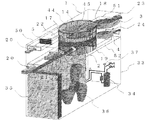
図7は、本発明の実施の形態2における、加湿機能を有する空気調和機の室外側の概略構成図であり、実施の形態1で説明した加湿ユニット1を、空気調和機の室外機33の上部に一体化して設置したものである。室外機33の内部には、周知のとおり、圧縮機34、室外機熱交換器35、室外機送風機36、および膨張弁37などが設置され、図示しない室内機の熱交換器と接続されて、ヒートポンプサイクルを形成している。加湿ユニット1については、実施の形態1と同一であるため説明を割愛する。
Embodiment 2. FIG.
FIG. 7 is a schematic configuration diagram of the outdoor side of the air conditioner having a humidifying function according to the second embodiment of the present invention. The humidifying unit 1 described in the first embodiment is replaced with the outdoor unit 33 of the air conditioner. It is installed in the upper part. Inside the outdoor unit 33, as is well known, a compressor 34, an outdoor unit heat exchanger 35, an outdoor unit blower 36, an expansion valve 37, and the like are installed and connected to a heat exchanger of an indoor unit (not shown) A heat pump cycle is formed. Since the humidification unit 1 is the same as that of the first embodiment, description thereof is omitted.

次に動作の一例について説明する。動作についても、加湿ユニット1内部については、実施の形態1と同一であるため説明を割愛する。ヒートポンプサイクルが暖房運転を行っているとき、実施の形態1にて説明したように、風路切換ダンパの位置が図4の<A>および<B>となるように、第1の風路切換ダンパ14および第2の風路切換ダンパ15を繰り返し切り換えることにより、乾燥空気である吸着出口空気23、および高温高湿空気である再生出口空気24が、連続的に加湿ユニット1から排出される。このとき、再生出口空気24は、室内と室外を接続するダクトなどを経由して、再生空気送風手段4により室内へと搬送され、室内機から排出される高温空気とともに室内へ供給され、室内を暖房加湿する。   Next, an example of the operation will be described. Regarding the operation, the inside of the humidifying unit 1 is the same as that of the first embodiment, and thus the description thereof is omitted. When the heat pump cycle performs the heating operation, as described in the first embodiment, the first air path switching is performed so that the position of the air path switching damper is <A> and <B> in FIG. By repeatedly switching the damper 14 and the second air path switching damper 15, the adsorption outlet air 23 that is dry air and the regeneration outlet air 24 that is high-temperature and high-humidity air are continuously discharged from the humidifying unit 1. At this time, the regeneration outlet air 24 is conveyed into the room by the regeneration air blowing means 4 via a duct connecting the room and the outside, and is supplied into the room together with the high-temperature air discharged from the indoor unit. Heat and humidify.

このように、加湿ユニット1を空気調和機の室外機33の上部に一体化して設置することにより、新たに加湿ユニット1を設置するための床スペースを確保することなく、加湿機能を有する空気調和機を得ることができる。また、ヒートポンプサイクルの暖房運転と同時に、連続的に加湿空気を室内に供給することが可能となるため、暖房時の乾燥を防ぐことができるという効果が得られる。   Thus, the air conditioning which has a humidification function, without securing the floor space for newly installing the humidification unit 1 by installing the humidification unit 1 integrally in the upper part of the outdoor unit 33 of an air conditioner. You can get a chance. Moreover, since it becomes possible to supply humidified air continuously indoors simultaneously with the heating operation of a heat pump cycle, the effect that the drying at the time of heating can be prevented is acquired.

図7では、加湿ユニット1を空気調和機の室外機33の上部に一体化して設置しているが、室外機送風機36の送風を阻害しない位置であれば、室外機33の側面、あるいは底面に一体化して設置してもよい。どちらの場合でも、再生出口空気24を室内に導くことが可能であり、底面に設置した場合は設置床スペースも変わらないため、加湿ユニット1を上部に一体化して設置した場合と同様の効果が得られる。 In FIG. 7, the humidifying unit 1 is integrated and installed on the upper part of the outdoor unit 33 of the air conditioner. However, if the humidifying unit 1 is in a position that does not hinder the ventilation of the outdoor unit blower 36, You may install it integrally. In either case, the regeneration outlet air 24 can be guided into the room, and when installed on the bottom surface, the installation floor space does not change. Therefore, the same effect as when the humidification unit 1 is integrated and installed at the top is obtained. can get.

また図7では、実施の形態1で説明したように、吸着材2における吸着工程と再生工程の空気の流れ方向が対向となるように、第1の風路仕切枠6に再生空気吸気口17、吸着空気排気口18、および第4の風路仕切枠9に吸着空気吸気口16、再生空気排気口19を設置しているが、同じ対向流であって、第1の風路仕切枠6と第4の風路仕切枠9の上下位置を逆転させてもよく、また、第1の風路仕切枠6に設置された吸着空気吸気口16と、第4の風路仕切枠9に設置された吸着空気排気口18の位置を逆転させ、吸着材2における吸着工程と再生工程が並行流で行われるようにしてもよい。この場合、実施の形態1で説明した効果に加え、吸着空気排気口18が室外機熱交換器35の空気吸込口付近である第4の風路仕切枠9に配置されることになり、乾燥しかつ吸着熱により外気よりも若干温度が上昇した吸着出口空気23が、ヒートポンプサイクルの暖房運転時に、蒸発器である室外機熱交換器35に吸い込まれることになるので、室外機熱交換器35における着霜を抑制し、暖房運転効率を向上させるという効果も期待できる。 In FIG. 7, as described in the first embodiment, the regeneration air intake port 17 is provided in the first air passage partition frame 6 so that the air flow directions in the adsorption process and the regeneration process in the adsorbent 2 are opposed to each other. The adsorbed air exhaust port 18 and the fourth air passage partition frame 9 are provided with the adsorbed air intake port 16 and the regeneration air exhaust port 19, but they have the same counterflow and the first air channel partition frame 6. And the upper and lower positions of the fourth airway partition frame 9 may be reversed, and the intake air intake port 16 installed in the first airway partition frame 6 and the fourth airway partition frame 9 are installed. The position of the adsorbed air exhaust port 18 may be reversed so that the adsorption process and the regeneration process in the adsorbent 2 are performed in parallel flow. In this case, in addition to the effects described in the first embodiment, the adsorption air exhaust port 18 is disposed in the fourth airway partition frame 9 in the vicinity of the air intake port of the outdoor unit heat exchanger 35, and drying is performed. In addition, the adsorption outlet air 23 whose temperature is slightly higher than the outside air due to the heat of adsorption is sucked into the outdoor unit heat exchanger 35 which is an evaporator during the heating operation of the heat pump cycle, so the outdoor unit heat exchanger 35 The effect of suppressing the frost formation in and improving the heating operation efficiency can also be expected.

また図7では、吸着出口空気23の排気専用として、吸着空気送風手段3を設置しているが、加湿ユニット1を空気調和機の室外機33に一体化して設置しているので、室外機33の上面に連通口を設け、室外機送風機36によって取り込まれた空気の一部を、吸着空気吸気口16に導いてもよい。この場合、吸着空気送風手段3として室外機送風機36が兼用され、加湿ユニット1に設置する送風機は再生空気送風手段4だけでよいので、送風機の数を削減でき低コストとなる。 In FIG. 7, the adsorption air blowing means 3 is installed exclusively for exhausting the adsorption outlet air 23. However, since the humidification unit 1 is integrated with the outdoor unit 33 of the air conditioner, the outdoor unit 33 is installed. A communication port may be provided on the upper surface of the air-conditioner, and a part of the air taken in by the outdoor unit blower 36 may be guided to the adsorption air intake port 16. In this case, since the outdoor unit blower 36 is also used as the adsorbed air blowing unit 3 and only the regenerative air blowing unit 4 is required to be installed in the humidifying unit 1, the number of blowers can be reduced and the cost is reduced.

実施の形態3.
図8は、本発明の実施の形態3における、加湿機能を有する空気調和機の加湿装置の概略設置図であり、実施の形態1で説明した加湿ユニット1を、建物の外壁38に設置したものである。空気調和機のヒートポンプサイクルにおける各部品については図示していないが、室外機33と室内機を接続する冷媒配管は壁穴39を介して設置され、吸着空気排気口18と連通する室外排気口40は室外に開放され、再生空気排気口19と連通する室内接続口41は壁穴39に最短距離で接続されている。加湿ユニット1については、実施の形態1と同一であるため説明を割愛する。
Embodiment 3 FIG.
FIG. 8 is a schematic installation diagram of a humidifying device for an air conditioner having a humidifying function in Embodiment 3 of the present invention, in which the humidifying unit 1 described in Embodiment 1 is installed on the outer wall 38 of a building. It is. Although not shown in the drawings for each component in the heat pump cycle of the air conditioner, the refrigerant pipe connecting the outdoor unit 33 and the indoor unit is installed through the wall hole 39 and is connected to the adsorbed air exhaust port 18. Is open to the outside and the indoor connection port 41 communicating with the regeneration air exhaust port 19 is connected to the wall hole 39 at the shortest distance. Since the humidification unit 1 is the same as that of the first embodiment, description thereof is omitted.

次に動作の一例について説明する。動作についても、加湿ユニット1内部については、実施の形態1と同一であるため説明を割愛する。ヒートポンプサイクルが暖房運転を行っているとき、実施の形態1にて説明したように、風路切換ダンパの位置が図4の<A>および<B>となるように、第1の風路切換ダンパ14および第2の風路切換ダンパ15を繰り返し切り換えることにより、乾燥空気である吸着出口空気23、および高温高湿空気である再生出口空気24が、連続的に加湿ユニット1から排出される。このとき、加湿ユニット1が建物の外壁38に直接設置され、室内接続口41と壁穴39とは密着しているので、再生出口空気24は、ダクトなどを経由せずに、再生空気送風手段4により最短距離で室内へと搬送され、室内機から排出される高温空気とともに室内へ供給され、室内を暖房加湿する。   Next, an example of the operation will be described. Regarding the operation, the inside of the humidifying unit 1 is the same as that of the first embodiment, and thus the description thereof is omitted. When the heat pump cycle performs the heating operation, as described in the first embodiment, the first air path switching is performed so that the position of the air path switching damper is <A> and <B> in FIG. By repeatedly switching the damper 14 and the second air path switching damper 15, the adsorption outlet air 23 that is dry air and the regeneration outlet air 24 that is high-temperature and high-humidity air are continuously discharged from the humidifying unit 1. At this time, since the humidification unit 1 is directly installed on the outer wall 38 of the building and the indoor connection port 41 and the wall hole 39 are in close contact with each other, the regeneration outlet air 24 can be regenerated air blowing means without going through a duct or the like. 4 is carried into the room at the shortest distance and supplied to the room together with the high-temperature air discharged from the indoor unit to heat and humidify the room.

このように、加湿ユニット1を建物の外壁38に設置して、室内接続口41を壁穴39と接続し、その際に搬送距離を最短とすることで低コスト化が可能となるだけでなく、風路圧損および騒音が小さくなり、再生空気送風手段4を小型化することも可能となり、信頼性が高くコンパクトな加湿機能を有する空気調和機を得ることができる。また、高湿である再生出口空気24をダクトで搬送する場合、特に冬場ではダクトが外気により冷却されるため、内部で結露する危険性が高いが、搬送距離を最短とすることで、加湿ユニット1で生成した加湿空気を、ロスなく有効に室内に供給することが可能となる。また、ヒートポンプサイクルの暖房運転と同時に、連続的に加湿空気を室内に供給することが可能となるため、暖房時の乾燥を防ぐことができるという効果が得られる。   In this way, the humidification unit 1 is installed on the outer wall 38 of the building, the indoor connection port 41 is connected to the wall hole 39, and at that time, not only can the cost be reduced by shortening the transport distance. The air path pressure loss and noise are reduced, the regenerative air blowing means 4 can be downsized, and an air conditioner having a highly reliable and compact humidifying function can be obtained. Further, when the regeneration outlet air 24 having high humidity is transported by a duct, the duct is cooled by the outside air particularly in winter, so there is a high risk of dew condensation inside. It becomes possible to supply the humidified air produced | generated by 1 indoors effectively without loss. Moreover, since it becomes possible to supply humidified air continuously indoors simultaneously with the heating operation of a heat pump cycle, the effect that the drying at the time of heating can be prevented is acquired.

図8では、室外排気口40を加湿ユニット1の前面に設置し、吸着出口空気23を外気に開放しているが、室外排気口40から空気調和機の室外機熱交換器35の空気吸込口付近へと導くような風路を設け、吸着出口空気23を室外機33に吸い込ませてもよい。この場合、吸着出口空気23は乾燥し、かつ吸着熱により外気よりも若干温度が上昇しているため、暖房運転時に蒸発器である室外機熱交換器35における着霜を抑制し、暖房運転効率を向上させるという効果も期待できる。 In FIG. 8, although the outdoor exhaust port 40 is installed in the front surface of the humidification unit 1, and the adsorption | suction outlet air 23 is open | released to external air, the air inlet port of the outdoor unit heat exchanger 35 of an air conditioner from the outdoor exhaust port 40 An air passage leading to the vicinity may be provided, and the suction outlet air 23 may be sucked into the outdoor unit 33. In this case, since the adsorption outlet air 23 is dry and the temperature is slightly higher than the outside air due to adsorption heat, frost formation in the outdoor unit heat exchanger 35 as an evaporator is suppressed during heating operation, and heating operation efficiency is improved. The effect of improving can also be expected.

実施の形態4.
図9は、本発明の実施の形態4における、加湿機能を有する空気調和機の加湿装置の概略設置図であり、実施の形態1で説明した加湿ユニット1を、建物の内壁42に設置したものである。空気調和機のヒートポンプサイクルにおける各部品については図示していないが、室外機33と室内機を接続する冷媒配管は壁穴39を介して設置され、また吸着空気排気口18と連通する室外排気口40は、壁穴39と接続されており、再生空気排気口19と連通する室内接続口41は室内に開放されている。加湿ユニット1については、実施の形態1と同一であるため説明を割愛する。
Embodiment 4 FIG.
FIG. 9 is a schematic installation diagram of a humidifying device for an air conditioner having a humidifying function according to the fourth embodiment of the present invention, in which the humidifying unit 1 described in the first embodiment is installed on the inner wall 42 of the building. It is. Although not shown in the drawings for each component in the heat pump cycle of the air conditioner, the refrigerant pipe connecting the outdoor unit 33 and the indoor unit is installed through the wall hole 39 and is connected to the adsorbed air exhaust port 18. Reference numeral 40 is connected to the wall hole 39, and an indoor connection port 41 communicating with the regeneration air exhaust port 19 is opened indoors. Since the humidification unit 1 is the same as that of the first embodiment, description thereof is omitted.

次に動作の一例について説明する。動作についても、加湿ユニット1内部については、基本的に実施の形態1と同一であるため説明を割愛するが、吸着空気吸気口16から吸い込まれる吸着入口空気21は、外気ではなく室内空気43、また再生空気吸気口17から吸い込まれる再生入口空気22は、外気ではなく室内空気43を再生空気加熱手段5で昇温した空気となる。ヒートポンプサイクルが暖房運転を行っているとき、実施の形態1にて説明したように、風路切換ダンパの位置が図4の<A>および<B>となるように、第1の風路切換ダンパ14および第2の風路切換ダンパ15を繰り返し切り換えることにより、乾燥空気である吸着出口空気23、および高温高湿空気である再生出口空気24が、連続的に加湿ユニット1から排出される。このとき、加湿ユニット1を建物の内壁42に接続し、室内接続口41は室内に開放されているので、再生出口空気24は、最短距離のダクトにて、再生空気送風手段4により室内へ供給され、室内機から排出される高温空気とともに室内を暖房加湿する。   Next, an example of the operation will be described. Regarding the operation, the inside of the humidifying unit 1 is basically the same as that of the first embodiment, and thus the description thereof is omitted. However, the suction inlet air 21 sucked from the suction air suction port 16 is not the outside air but the indoor air 43, Further, the regeneration inlet air 22 sucked from the regeneration air intake port 17 is not the outside air but the air in which the room air 43 is heated by the regeneration air heating means 5. When the heat pump cycle performs the heating operation, as described in the first embodiment, the first air path switching is performed so that the position of the air path switching damper is <A> and <B> in FIG. By repeatedly switching the damper 14 and the second air path switching damper 15, the adsorption outlet air 23 that is dry air and the regeneration outlet air 24 that is high-temperature and high-humidity air are continuously discharged from the humidifying unit 1. At this time, the humidifying unit 1 is connected to the inner wall 42 of the building, and the indoor connection port 41 is opened indoors. Therefore, the regeneration outlet air 24 is supplied into the room by the regeneration air blowing means 4 through the shortest distance duct. Then, the room is heated and humidified together with the high-temperature air discharged from the indoor unit.

このように、加湿ユニット1を建物の内壁42に最短距離となるように設置して、室内接続口41を室内に開放することにより、実施の形態6と同様に、再生出口空気24を室内へ搬送するためのダクトを最小限に抑えることができ、低コストが可能となる。さらに、再生空気送風手段4を小型化することにより、コンパクトな加湿機能を有する空気調和機を得ることができるだけでなく、ダクト騒音やダクト内結露などの問題を回避することも可能となり、信頼性を確保できる効果が得られる。また、吸着入口空気21として室内空気を使用するので、加湿ユニット1の内部に室温以下の空気が流れることはなく、吸着風路を外気が流れる場合よりも、ユニット内部において結露が発生する危険性を回避できるという効果が得られる。さらに、再生入口空気22として暖房された室内空気を使用するので、吸着材2において水分の再生に必要な空気温度を得るために、再生空気加熱手段5にて昇温に必要な熱量が軽減されるという省エネ効果も得られる。また、ヒートポンプサイクルの暖房運転と同時に、連続的に加湿空気を室内に供給することが可能となるため、暖房時の乾燥を防ぐことができるという効果が得られる。   In this way, the humidification unit 1 is installed on the inner wall 42 of the building so as to have the shortest distance, and the indoor connection port 41 is opened indoors, thereby allowing the regeneration outlet air 24 to enter the room as in the sixth embodiment. It is possible to minimize the number of ducts for conveyance, and it is possible to reduce costs. Further, by reducing the size of the regenerative air blowing means 4, it is possible not only to obtain a compact air conditioner having a humidifying function, but also to avoid problems such as duct noise and condensation in the duct. Is obtained. Further, since room air is used as the adsorption inlet air 21, air below room temperature does not flow inside the humidifying unit 1, and there is a risk that condensation will occur inside the unit, compared to when outside air flows through the adsorption air passage. Can be obtained. Furthermore, since the heated indoor air is used as the regeneration inlet air 22, the regeneration air heating means 5 reduces the amount of heat necessary for raising the temperature in order to obtain the air temperature necessary for the regeneration of moisture in the adsorbent 2. Energy saving effect. Moreover, since it becomes possible to supply humidified air continuously indoors simultaneously with the heating operation of a heat pump cycle, the effect that the drying at the time of heating can be prevented is acquired.

図9では、吸着空気吸気口16を室内に開放し、吸着入口空気21として暖房された室内空気を吸い込ませているが、壁穴39を2分割して一方を吸着空気吸気口16と接続し、あるいは別の壁穴を設けて吸着空気吸気口16と接続することにより、吸着入口空気21として外気を吸い込ませてもよい。この場合、吸着材2に担持された吸着剤は、相対湿度の高い外気中の水分を吸着することになるので、吸着剤が吸着できる水分量が増加し、室内空気を吸着させるよりも室内に供給される加湿量としては増加するという効果が得られる。 In FIG. 9, the adsorbed air intake port 16 is opened indoors and the heated indoor air is sucked as the adsorbed inlet air 21, but the wall hole 39 is divided into two and one is connected to the adsorbed air intake port 16. Alternatively, another wall hole may be provided and connected to the suction air intake port 16 to suck in the outside air as the suction inlet air 21. In this case, since the adsorbent carried on the adsorbent 2 adsorbs moisture in the outside air having a high relative humidity, the amount of moisture that can be adsorbed by the adsorbent increases, so that indoor air can be adsorbed rather than adsorbed indoor air. The effect of increasing the amount of humidification supplied is obtained.

1 加湿ユニット
2 吸着材
3 吸着空気送風手段
4 再生空気送風手段
5 再生空気加熱手段
6 第1の風路仕切枠
7 第2の風路仕切枠
8 第3の風路仕切枠
9 第4の風路仕切枠
10 第1の風路仕切板
11 第2の風路仕切板
12 第3の風路仕切板
13 第4の風路仕切板
14 第1の風路切換ダンパ
15 第2の風路切換ダンパ
16 吸着空気吸気口
17 再生空気吸気口
18 吸着空気排気口
19 再生空気排気口
20 室外空気
21 吸着入口空気
22 再生入口空気
23 吸着出口空気
24 再生出口空気
25 第1の風路仕切板のリブ
26 第2の風路仕切板のリブ
27 第3の風路仕切板のリブ
28 第4の風路仕切板のリブ
29 第1の風路切換ダンパの上部端板
30 第1の風路切換ダンパの下部端板
31 第2の風路切換ダンパの上部端板
32 第2の風路切換ダンパの下部端板
33 室外機
34 圧縮機
35 室外機熱交換器
36 室外機送風機
37 膨張弁
38 建物の外壁
39 壁穴
40 室外排気口
41 室内接続口
42 建物の内壁
43 室内空気
44 吸脱着機構部
45 中心軸
46 舌部
47 羽
48 順方向部分
49 吸着空気吸気路
50 再生空気吸気路
51 吸着空気排気路
52 再生空気排気路
141、142 第1の風路切換ダンパの開口部
143、144 第1の風路切換ダンパの閉塞部
151、152 第2の風路切換ダンパの開口部
153、154 第2の風路切換ダンパの閉塞部
DESCRIPTION OF SYMBOLS 1 Humidification unit 2 Adsorbent 3 Adsorption air ventilation means 4 Regeneration air ventilation means 5 Regeneration air heating means 6 1st air path partition frame 7 2nd air path partition frame 8 3rd air path partition frame 9 4th wind Road partition frame 10 First air path partition plate 11 Second air path partition plate 12 Third air path partition plate 13 Fourth air path partition plate 14 First air path switching damper 15 Second air path switching Damper 16 Adsorption air intake port 17 Regeneration air intake port 18 Adsorption air exhaust port 19 Regeneration air exhaust port 20 Outdoor air 21 Adsorption inlet air 22 Regeneration inlet air 23 Adsorption outlet air 24 Regeneration outlet air 25 Rib of first air passage partition plate 26 Ribs of the second airway partition plate 27 Ribs of the third airway partition plate 28 Ribs of the fourth airway partition plate 29 Upper end plate 30 of the first airway switching damper First airway switching damper Lower end plate 31 Upper end plate 32 of second air path switching damper Second air path cut Damper lower end plate 33 Outdoor unit 34 Compressor 35 Outdoor unit heat exchanger 36 Outdoor unit blower 37 Expansion valve 38 Building outer wall 39 Wall hole 40 Outdoor exhaust port 41 Indoor connection port 42 Inner wall 43 Indoor air 44 Adsorption / desorption mechanism Portion 45 Central shaft 46 Tongue 47 Wings 48 Forward portion 49 Adsorption air intake passage 50 Regeneration air intake passage 51 Adsorption air exhaust passage 52 Regeneration air exhaust passages 141, 142 Openings 143, 144 of the first air path switching damper Closures 151 and 152 of the first air path switching damper Openings 153 and 154 of the second air path switching damper Closure part of the second air path switching damper

Claims (6)

空気中の水分を吸着する吸着材が固定状態に配置されて内部が2つの部位に分割された吸脱着機構部と、
前記吸脱着機構部の内部の前記各部位にそれぞれ配置された風路切換ダンパと、
前記吸脱着機構部内を通って形成され前記吸着材に前記風路切換ダンパを介して吸着用空気を供給する吸着空気通気路と、
前記吸脱着機構部内を通って形成され前記吸着材に前記風路切換ダンパを介して前記吸着用空気とは逆向きに再生用空気を供給する再生空気通気路と、
前記吸着材の空気が通過する表面を2つの領域に分割する吸着材風路仕切板を有する吸着材風路仕切枠と、
前記吸着材に供給される前記再生用空気を加熱する加熱手段と、
を備え、
前記風路切換ダンパは、前記吸着材に対する前記吸着用空気と前記再生用空気の通過する領域とを交互に切り換え、
前記吸脱着機構部は、前記各部位に配置された前記風路切換ダンパに流れる空気を2つに分けるとともに、前記吸着空気通気路と前記再生空気通気路とを仕切る通気路風路仕切枠を有し、
前記通気路風路仕切枠は、円筒状の枠板と、前記枠板内を2分する通気路風路仕切板と、からなり、
一方の部位に設けられた前記通気路風路仕切枠の枠板に前記通気路風路仕切板をはさんで吸着用空気の吸気口と再生用空気の排気口とを形成するとともに、
他方の部位に設けられた前記通気路風路仕切枠の枠板に前記通気路風路仕切板をはさんで吸着用空気の排気口と再生用空気の吸気口とを形成し、
前記吸着用空気の吸気口および前記再生用空気の吸気口に、吸着用空気の吸気路および再生用空気の吸気路をそれぞれ接続し、これら各吸気路は空気の流れが前記通気路風路仕切板に平行になるよう設けた加湿装置。
An adsorption / desorption mechanism part in which an adsorbent that adsorbs moisture in the air is arranged in a fixed state and the inside is divided into two parts;
An air path switching damper disposed in each of the parts inside the adsorption / desorption mechanism,
An adsorption air ventilation path that is formed through the adsorption / desorption mechanism and supplies adsorption air to the adsorbent via the air path switching damper;
A regenerative air ventilation path that is formed through the adsorption / desorption mechanism section and supplies regeneration air to the adsorbent through the air path switching damper in a direction opposite to the adsorption air;
An adsorbent air channel partition frame having an adsorbent air channel partition plate that divides the surface through which the air of the adsorbent passes into two regions;
Heating means for heating the regeneration air supplied to the adsorbent;
With
The air path switching damper alternately switches between the adsorption air for the adsorbent and the region through which the regeneration air passes,
The adsorption / desorption mechanism section divides the air flowing through the air path switching dampers disposed in the respective parts into two, and includes an air path air path partition frame that partitions the adsorption air air path and the regeneration air air path. Have
The ventilation path air channel partition frame is composed of a cylindrical frame plate and an air path air channel partition plate that bisects the inside of the frame plate,
While forming a suction air intake port and a regeneration air exhaust port across the ventilation channel air channel partition plate to the frame plate of the ventilation channel air channel partition frame provided in one part,
Forming an air intake port for adsorption air and an air intake port for regeneration air across the air channel air channel partition plate on the frame plate of the air channel air channel partition frame provided in the other part;
An adsorption air intake passage and a regeneration air intake passage are connected to the adsorption air intake port and the regeneration air intake port, respectively. Humidifier provided parallel to the plate.
前記吸着空気通気路の排気路および前記再生空気通気路の排気路には、それぞれ吸着空気送風手段、再生空気送風手段が設けられ、
前記吸着空気通気路の排気路は、その空気の流れと前記吸着空気送風手段の回転方向とが同じ方向になるよう接続され、
前記再生空気通気路の排気路は、その空気の流れと前記再生空気送風手段の回転方向とが同じ方向になるよう接続されている請求項1記載の加湿装置。
An adsorption air blowing means and a regeneration air blowing means are provided in the exhaust path of the adsorption air ventilation path and the exhaust path of the regeneration air ventilation path, respectively.
The exhaust path of the adsorption air ventilation path is connected so that the air flow and the rotation direction of the adsorption air blowing means are in the same direction,
The humidification device according to claim 1, wherein the exhaust air passage of the regeneration air ventilation passage is connected so that the air flow and the rotation direction of the regeneration air blowing means are in the same direction.
前記吸着材風路仕切枠の前記吸着材風路仕切板と前記通気路風路仕切枠の前記通気路風路仕切板とが直交するよう対向して配置され、これら風路仕切枠の間に介在させて前記風路切換ダンパが配置された請求項1又は2記載の加湿装置。 The adsorbent air channel partition plate of the adsorbent air channel partition frame and the air channel air channel partition plate of the air channel air channel partition frame are arranged so as to be orthogonal to each other, and between these air channel partition frames. The humidifying device according to claim 1 or 2, wherein the air path switching damper is disposed therebetween. 前記風路切換ダンパは、中心角略90°の扇形形状を有する2つの閉塞部分が、中心角略90°の扇形形状を有する2つの開口部分を形成するように接続された形状であることを特徴とする請求項3記載の加湿装置。 The air path switching damper has a shape in which two closed portions having a sector shape with a central angle of about 90 ° are connected so as to form two opening portions having a sector shape with a central angle of about 90 °. The humidifying device according to claim 3. 前記吸着材風路仕切板及び前記通気路風路仕切板の側面に垂直な方向に設けられたリブと、
前記風路切換ダンパの閉塞部分の半径部分全体に、前記吸着材側またはその反対側の少なくとも一方に設けられた端板と、を有する請求項4記載の加湿装置。
A rib provided in a direction perpendicular to the side surface of the adsorbent air passage partition plate and the air passage air passage partition plate;
The humidifying device according to claim 4, further comprising: an end plate provided on at least one of the adsorbent side and the opposite side of the entire radius portion of the closed portion of the air path switching damper.
2つの前記風路切換ダンパが連動して、前記吸脱着機構部の中心軸を回転軸として角度90°の正逆回転を繰り返すことにより、風路切換を行う請求項4又は5記載の加湿装置。 The humidifier according to claim 4 or 5, wherein the two air path switching dampers are linked to perform air path switching by repeating forward and reverse rotation at an angle of 90 ° with the central axis of the adsorption / desorption mechanism portion as a rotation axis. .
JP2009156840A 2009-07-01 2009-07-01 Humidifier and air conditioner equipped with humidifier Active JP4888529B2 (en)

Priority Applications (1)

Application Number Priority Date Filing Date Title
JP2009156840A JP4888529B2 (en) 2009-07-01 2009-07-01 Humidifier and air conditioner equipped with humidifier

Applications Claiming Priority (1)

Application Number Priority Date Filing Date Title
JP2009156840A JP4888529B2 (en) 2009-07-01 2009-07-01 Humidifier and air conditioner equipped with humidifier

Publications (2)

Publication Number Publication Date
JP2011012876A JP2011012876A (en) 2011-01-20
JP4888529B2 true JP4888529B2 (en) 2012-02-29

Family

ID=43591962

Family Applications (1)

Application Number Title Priority Date Filing Date
JP2009156840A Active JP4888529B2 (en) 2009-07-01 2009-07-01 Humidifier and air conditioner equipped with humidifier

Country Status (1)

Country Link
JP (1) JP4888529B2 (en)

Families Citing this family (3)

* Cited by examiner, † Cited by third party
Publication number Priority date Publication date Assignee Title
CN104976747A (en) * 2014-04-03 2015-10-14 杭州品悦电器有限公司 Air guide mechanism with multiple selective air openings
GB2545114C (en) 2014-09-26 2020-07-29 Mitsubishi Electric Corp Dehumidifier
JP6849035B1 (en) * 2019-09-30 2021-03-24 ダイキン工業株式会社 Humidification unit

Also Published As

Publication number Publication date
JP2011012876A (en) 2011-01-20

Similar Documents

Publication Publication Date Title
CN215336790U (en) Device for adjusting humidity
JP4337402B2 (en) Air conditioner, operation method of air conditioner
JP2630746B2 (en) Total heat exchange ventilator
JP4639485B2 (en) Air conditioner
KR101398897B1 (en) Ventilation unit and air conditioner having the same
JP4888529B2 (en) Humidifier and air conditioner equipped with humidifier
JP5003697B2 (en) Humidifier, method of controlling humidifier, and air conditioner having humidifier
JP6492445B2 (en) Sirocco fan and pneumatic conveying device
JP2007101055A (en) Humidification unit and outdoor machine of air conditioner
JP2002162083A (en) Ventilating humidity control system
JP3642022B2 (en) Humidity control equipment
JP4772099B2 (en) Dehumidifying / humidifying device, air conditioner, and air leakage prevention structure
JP4165102B2 (en) Humidity control system
JP4776642B2 (en) Humidifier and air conditioner with humidification function
JP5084885B2 (en) Humidified air transfer duct and air conditioner
JP2835695B2 (en) Total heat exchange ventilator
JP2003004255A (en) Air conditioner
JP4585011B2 (en) Humidified air transfer duct, humidifier, and air conditioner
JP2019184124A (en) Air conditioner
JP2014119180A (en) Humidity controller
JP2006170492A (en) Humidity controller and humidity controlling system
JP5621535B2 (en) Air conditioner
JP6881578B2 (en) Humidity control unit
JP4535192B2 (en) Humidification unit
JP4866222B2 (en) Air conditioner

Legal Events

Date Code Title Description
A977 Report on retrieval

Free format text: JAPANESE INTERMEDIATE CODE: A971007

Effective date: 20110801

TRDD Decision of grant or rejection written
A01 Written decision to grant a patent or to grant a registration (utility model)

Free format text: JAPANESE INTERMEDIATE CODE: A01

Effective date: 20111115

A01 Written decision to grant a patent or to grant a registration (utility model)

Free format text: JAPANESE INTERMEDIATE CODE: A01

A61 First payment of annual fees (during grant procedure)

Free format text: JAPANESE INTERMEDIATE CODE: A61

Effective date: 20111128

R151 Written notification of patent or utility model registration

Ref document number: 4888529

Country of ref document: JP

Free format text: JAPANESE INTERMEDIATE CODE: R151

FPAY Renewal fee payment (event date is renewal date of database)

Free format text: PAYMENT UNTIL: 20141222

Year of fee payment: 3

R250 Receipt of annual fees

Free format text: JAPANESE INTERMEDIATE CODE: R250

R250 Receipt of annual fees

Free format text: JAPANESE INTERMEDIATE CODE: R250

R250 Receipt of annual fees

Free format text: JAPANESE INTERMEDIATE CODE: R250

R250 Receipt of annual fees

Free format text: JAPANESE INTERMEDIATE CODE: R250

R250 Receipt of annual fees

Free format text: JAPANESE INTERMEDIATE CODE: R250

R250 Receipt of annual fees

Free format text: JAPANESE INTERMEDIATE CODE: R250

R250 Receipt of annual fees

Free format text: JAPANESE INTERMEDIATE CODE: R250

R250 Receipt of annual fees

Free format text: JAPANESE INTERMEDIATE CODE: R250