JP4887324B2 - Printing device - Google Patents
Printing device Download PDFInfo
- Publication number
- JP4887324B2 JP4887324B2 JP2008091183A JP2008091183A JP4887324B2 JP 4887324 B2 JP4887324 B2 JP 4887324B2 JP 2008091183 A JP2008091183 A JP 2008091183A JP 2008091183 A JP2008091183 A JP 2008091183A JP 4887324 B2 JP4887324 B2 JP 4887324B2
- Authority
- JP
- Japan
- Prior art keywords
- printing
- unit
- syringe
- squeegee
- solder
- Prior art date
- Legal status (The legal status is an assumption and is not a legal conclusion. Google has not performed a legal analysis and makes no representation as to the accuracy of the status listed.)
- Active
Links
- 229910000679 solder Inorganic materials 0.000 claims description 110
- 238000012423 maintenance Methods 0.000 claims description 35
- 239000000758 substrate Substances 0.000 claims description 22
- 230000007246 mechanism Effects 0.000 description 35
- 238000007689 inspection Methods 0.000 description 31
- 230000003028 elevating effect Effects 0.000 description 16
- 230000004048 modification Effects 0.000 description 12
- 238000012986 modification Methods 0.000 description 12
- 230000032258 transport Effects 0.000 description 4
- 238000010586 diagram Methods 0.000 description 3
- 238000007599 discharging Methods 0.000 description 2
- 238000000034 method Methods 0.000 description 2
- 230000002411 adverse Effects 0.000 description 1
- 238000004140 cleaning Methods 0.000 description 1
- 230000003247 decreasing effect Effects 0.000 description 1
- 230000000694 effects Effects 0.000 description 1
- 230000035939 shock Effects 0.000 description 1
- 238000005476 soldering Methods 0.000 description 1
Images


Landscapes
- Screen Printers (AREA)
- Electric Connection Of Electric Components To Printed Circuits (AREA)
Description
この発明は、印刷装置に関し、特に、半田を供給する半田供給部と、マスクを介して基板に所定のパターンの半田を印刷する印刷ユニットとを備えた印刷装置に関する。 The present invention relates to a printing apparatus, and more particularly, to a printing apparatus including a solder supply unit that supplies solder and a printing unit that prints a predetermined pattern of solder on a substrate via a mask.
従来、半田を供給する半田供給部と、マスクを介して基板に所定のパターンの半田を印刷する印刷ユニットとを備えた印刷装置が知られている(たとえば、特許文献1参照)。 2. Description of the Related Art Conventionally, a printing apparatus including a solder supply unit that supplies solder and a printing unit that prints a predetermined pattern of solder on a substrate via a mask is known (see, for example, Patent Document 1).
上記特許文献1には、下面が基板と当接するとともに所定のパターンの開口を有するマスク上を所定の印刷方向に往復移動する印刷ユニットと、印刷ユニットの移動方向に沿って印刷ユニットと並んで配置されるとともに、マスク上に半田ペーストを供給する半田供給部とを備えた印刷装置が開示されている。特許文献1による印刷装置は、半田供給部から半田ペーストが供給されたマスクの上面に対して印刷ユニットに取り付けられたスキージ(ヘラ部材)を当接させた状態で印刷ユニットを印刷方向に往復移動させることにより、基板に半田パターンを印刷するように構成されている。なお、この特許文献1では、半田供給部が印刷ユニットと一体的に印刷方向に移動するか否かは明記されていない。
In the above-mentioned
しかしながら、上記特許文献1の印刷装置では、印刷ユニットと半田供給部とが、印刷方向に並んで配置されているので、作業者が印刷装置の点検および保守作業を印刷ユニット側から行う場合には、半田供給部が印刷ユニットを隔てて奥側に位置することになる。このため、半田供給部の点検および保守作業の作業性が悪くなるという問題点がある。一方、作業者が半田供給部の点検および保守作業を半田供給部側から行う場合には、印刷ユニットが半田供給部を隔てて奥側に位置することになるので、印刷ユニットの点検および保守作業の作業性が悪くなるという問題点がある。また、上記特許文献1において、半田供給部が印刷ユニットと一体的に印刷方向に移動するように構成した場合にも、上記と同様、半田供給部または印刷ユニットの点検および保守作業時の作業性が悪くなるという問題点が発生すると考えられる。
However, since the printing unit and the solder supply unit are arranged side by side in the printing direction in the printing apparatus of
この発明は、上記のような課題を解決するためになされたものであり、この発明の1つの目的は、印刷ユニットと半田供給部とが所定の印刷方向に並んで配置されるとともに、一体的に移動する構成においても、印刷ユニットおよび半田供給部の両方の点検および保守作業性を向上させることが可能な印刷装置を提供することである。 The present invention has been made to solve the above-described problems. One object of the present invention is to arrange a printing unit and a solder supply unit side by side in a predetermined printing direction, and to integrate them. It is another object of the present invention to provide a printing apparatus capable of improving the inspection and maintenance workability of both the printing unit and the solder supply unit even in the configuration of moving to the position.
上記目的を達成するために、この発明の一の局面による印刷装置は、下面に基板が配置され、所定のパターンの開口を有するマスクと、マスク上に半田を供給する半田供給部と、半田の供給されたマスクに対してヘラ部材を当接させた状態で、所定の印刷方向に移動することによりマスクを介して基板に所定のパターンの半田を印刷する印刷ユニットと、半田供給部を支持するアーム部材とを備え、半田供給部と印刷ユニットとは、印刷方向に沿って一体的に移動するように構成されており、印刷動作時には、半田供給部および印刷ユニットが、印刷方向に沿うように並ぶとともに、保守作業時には、半田供給部および印刷ユニットの少なくともいずれか一方が、印刷方向に沿うように並んだ印刷位置から印刷方向と異なる横方向に所定の距離だけ離間して、印刷方向から見て、半田供給部と印刷ユニットのヘラ部材の配置される位置とがオーバーラップしない退避位置に移動可能に構成されており、半田供給部は、アーム部材が回動されることによって印刷位置から退避位置に移動するように構成されている。 In order to achieve the above object, a printing apparatus according to an aspect of the present invention includes a mask having a substrate disposed on a lower surface and having a predetermined pattern of an opening, a solder supply unit for supplying solder onto the mask, With the spatula member in contact with the supplied mask, the printing unit that prints a predetermined pattern of solder on the substrate through the mask by moving in the predetermined printing direction and the solder supply unit are supported. An arm member, and the solder supply unit and the printing unit are configured to move integrally along the printing direction so that the solder supply unit and the printing unit are along the printing direction during a printing operation. In addition, at the time of maintenance work, at least one of the solder supply unit and the printing unit has a predetermined distance in the lateral direction different from the printing direction from the printing position where the soldering unit and the printing unit are aligned along the printing direction. Only apart, viewed from the printing direction, the solder is supplied portion and the arrangement is the position of the spatula member of the printing unit is movable in the retracted position where it does not overlap the solder supply unit, the arm member rotating It is configured to move from the printing position to the retracted position by being moved .
この一の局面による印刷装置では、上記のように、半田供給部および印刷ユニットの少なくともいずれか一方が、印刷方向に沿うように並んだ印刷位置から所定の退避位置に移動可能に構成することによって、半田供給部と印刷ユニットとが印刷方向に沿って配列されるとともに一体的に移動する構成においても、半田供給部および印刷ユニットの少なくともいずれか一方を退避位置に移動させることが可能である。このため、点検または保守作業時に、印刷方向に沿って配列される半田供給部および印刷ユニットを作業者の位置する作業位置の近傍にまで一体的に移動させるとともに、半田供給部および印刷ユニットのうちの作業者から見て手前側の方を退避位置に移動させれば、容易に奥側の方に対しても作業者が点検および保守作業を行うことができる。これにより、印刷ユニットおよび半田供給部の両方の点検および保守作業性を向上させることができる。また、点検および保守作業時に半田供給部を支持するアーム部材を回動させるだけで、容易に半田供給部を退避位置に移動させることができる。 In the printing apparatus according to the one aspect, as described above, at least one of the solder supply unit and the printing unit is configured to be movable from a printing position aligned along the printing direction to a predetermined retraction position. Even in a configuration in which the solder supply unit and the printing unit are arranged along the printing direction and move integrally, it is possible to move at least one of the solder supply unit and the printing unit to the retracted position. For this reason, during inspection or maintenance work, the solder supply unit and the printing unit arranged along the printing direction are integrally moved to the vicinity of the work position where the operator is located, and the solder supply unit and the printing unit are If the front side of the operator is moved to the retracted position, the operator can easily perform inspection and maintenance work on the back side. Thereby, inspection and maintenance workability of both the printing unit and the solder supply unit can be improved. In addition, the solder supply unit can be easily moved to the retracted position simply by rotating the arm member that supports the solder supply unit during inspection and maintenance work.
上記一の局面による印刷装置において、好ましくは、印刷方向に沿って直線状に移動可能な本体部と、両端が本体部に固定される支持板とを含むとともに、印刷ユニットが取り付けられる支持部材をさらに備え、半田供給部を支持するアーム部材は、本体部および支持板のいずれかにブラケットを介して取り付けられるとともに、支持部材に対して回動可能に構成されている。このように構成すれば、半田供給部はブラケットを介して、印刷方向に移動可能で、かつ、印刷ユニットが取り付けられる支持部材の本体部または支持板のいずれかに取り付けられるので、半田供給部を印刷ユニットと一体的に移動可能にしながら、アーム部材の回動により、容易に半田供給部を退避位置へ移動させることができる。なお、アーム部材は、アーム部材のみが支持部材に対して回動可能に構成されていてもよいし、アーム部材とブラケットとが一体的に回動することにより、支持部材に対して回動可能に構成されていてもよい。 In the printing apparatus according to the one aspect described above , preferably, the printing apparatus includes a main body portion that is linearly movable along the printing direction, and support plates that are fixed to the main body portions at both ends, and a support member to which the printing unit is attached. Further, the arm member that supports the solder supply unit is attached to either the main body unit or the support plate via a bracket, and is configured to be rotatable with respect to the support member. If comprised in this way, a solder supply part can be moved to a printing direction via a bracket, and since it is attached to either the main-body part or support plate of a support member to which a printing unit is attached, a solder supply part is attached. While being able to move integrally with the printing unit, the solder supply part can be easily moved to the retracted position by rotating the arm member. The arm member may be configured such that only the arm member can rotate with respect to the support member, or can rotate with respect to the support member by integrally rotating the arm member and the bracket. It may be configured.
上記一の局面による印刷装置において、好ましくは、印刷装置は、半田供給部および印刷ユニットの少なくともいずれか一方を、退避位置に保持する保持状態と、退避位置から移動可能とする解除状態とに切替可能な保持部材をさらに備える。このように構成すれば、点検および保守作業時に、半田供給部および印刷ユニットの少なくともいずれか一方を退避位置に保持することができるとともに、作業終了時には移動可能に切り替えることができる。これにより、点検および保守作業時に半田供給部または印刷ユニットが退避位置から移動するのを防止することができるので、半田供給部および印刷ユニットの点検および保守作業性をさらに向上させることができる。 The printing apparatus according to the aforementioned aspect preferably, the printing apparatus, at least one of the solder supply and printing unit, and hold the state that holds the retracted position, the release state to be movable from the retracted position further comprising a switchable hold member. According to this configuration, at the time of inspection and maintenance work, at least one of the solder supply unit and the printing unit can be held at the retracted position, and can be switched to be movable at the end of the work. Accordingly, it is possible to prevent the solder supply unit or the printing unit from moving from the retracted position during the inspection and maintenance work, so that the inspection and maintenance workability of the solder supply unit and the printing unit can be further improved.
以下、本発明の実施形態を図面に基づいて説明する。 Hereinafter, embodiments of the present invention will be described with reference to the drawings.
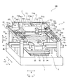
図1および図2は、それぞれ、本発明の一実施形態による印刷装置の全体構成を示す斜視図および側面図である。図3〜図6は、図1に示した印刷装置の構造を説明するための図である。以下、図1〜図6を参照して、本発明の一実施形態による印刷装置100の構造について説明する。
1 and 2 are a perspective view and a side view, respectively, showing the overall configuration of a printing apparatus according to an embodiment of the present invention. 3-6 is a figure for demonstrating the structure of the printing apparatus shown in FIG. The structure of the
本実施形態による印刷装置100は、図1および図2に示すように、基台1と、基台1上に設けられ、プリント基板200を搬送する基板搬送部2と、基板搬送部2の上方に設けられ、プリント基板200に対して半田の印刷を行う印刷部3とを備えている。なお、プリント基板200は、本発明の「基板」の一例である。基板搬送部2は、印刷前のプリント基板200の搬入を行うコンベア4aおよび印刷後のプリント基板200の搬出を行うコンベア4bと、コンベア4aおよび4bの間に設けられ、プリント基板200を保持した状態の後述するコンベア55を昇降し、プリント基板200を後述するマスク300の下面に当接する印刷位置O(図2参照)に配置するための基板位置決め昇降装置5とを含んでいる。コンベア4aおよび4bは基板搬送方向(X方向)に延びるように設けられている。また、印刷部3は、印刷に用いられるマスク300を支持するマスク支持部6と、マスク300を介してプリント基板200に半田を印刷する印刷機構部7と、印刷時に印刷機構部7を印刷方向(Y方向)に駆動する駆動部8とを含んでいる。また、マスク300は屈曲性を有する板状の部材からなり、所定のパターンの開口が形成された開口領域301を有する。マスク300は、その周囲が剛性の高い部材からなるフレーム302に固定される。
As shown in FIGS. 1 and 2, the
基板位置決め昇降装置5は、Y軸テーブル51と、X軸テーブル52と、R軸テーブル53と、Z軸テーブル54とを含み、X方向、Y方向、Z方向およびR方向(水平面内における回転方向)にプリント基板200を移動することが可能に構成されている。
The substrate
また、図2に示すように、基台1上にはY方向に延びるようにレール51aが設けられており、Y軸テーブル51はレール51aにスライド可能に取り付けられている。また、図示しないサーボモータおよびボールネジ機構によってY軸テーブル51がY方向に駆動されるように構成されている。Y軸テーブル51上にはX方向に延びるようにレール52aが設けられており、X軸テーブル52はレール52aにスライド可能に取り付けられているとともに、図示しないサーボモータおよびボールネジ機構によってX軸テーブル52がY軸テーブル51に対してX方向に駆動されるように構成されている。X軸テーブル52上には支持機構53aが設けられており、R軸テーブル53は支持機構53aにより水平面内で回転可能に支持されている。また、図示しないサーボモータおよびボールネジ機構によってR軸テーブル53が回転駆動されるように構成されている。R軸テーブル53にはZ軸テーブル54に固定されたZ方向に延びるガイド軸54aが挿入されているとともに、図示しないサーボモータおよびボールネジ機構54bによってZ軸テーブル54がR軸テーブル53に対してZ方向に駆動されるように構成されている。
As shown in FIG. 2, a
また、Z軸テーブル54にはX方向に延びる一対のコンベア55が配置されている。コンベア55はZ軸テーブル54が下降した状態でコンベア4aおよび4bと接続されるように配置されている。これにより、印刷前のプリント基板200をコンベア4aからコンベア55に乗り継がせて搬入し、印刷後のプリント基板200をコンベア55からコンベア4bに乗り継がせて搬出することが可能である。
The Z-axis table 54 is provided with a pair of
また、Z軸テーブル54には、一対のコンベア55の間の領域において上下方向(Z方向)に昇降可能な昇降テーブル56(図2参照)が設けられている。この昇降テーブル56の上面にはプリント基板200を下方から支える複数のピン(図示せず)が配置されている。また、昇降テーブル56は、上下方向に延びるスライド軸56aを介してZ軸テーブル54に対して上下方向にスライド可能に取り付けられているとともに、図示しないサーボモータおよびラック・ピニオン機構によってZ方向に駆動されるように構成されている。この昇降テーブル56が上昇されることにより、コンベア55上のプリント基板200が上昇されてクランプ片57aおよび57bと同一の高さ位置に位置されるとともに、クランプ片57aおよび57bにより保持されるプリント基板200の下面が図示しないピンによって支持される。また、印刷後、クランプ片57aおよび57bによるプリント基板200の保持が開放された後に昇降テーブル56が下降されることにより、プリント基板200をコンベア55上に載置することが可能である。印刷済みのプリント基板200がコンベア55上に載置された後、昇降テーブル56は、搬出、搬入されるプリント基板200と干渉しない位置までさらに下降させられる。
Further, the Z-axis table 54 is provided with a lifting table 56 (see FIG. 2) that can be lifted in the vertical direction (Z direction) in the region between the pair of
Z軸テーブル54には、コンベア55上のプリント基板200をクランプするクランプ片57aおよび57bが設けられている。クランプ片57aはZ軸テーブル54に対して固定的に設けられている一方、クランプ片57bはY方向に移動可能に設けられている。これにより、プリント基板200を押圧しながらクランプ片57bをY方向に移動させることにより、クランプ片57aおよびクランプ片57bにより、容易にプリント基板200をクランプすることが可能になる。
The Z-axis table 54 is provided with
マスク支持部6は、基板位置決め昇降装置5の上方において基台1のフレーム部材1aおよび1bを介して固定的に設置され、マスク300の外縁近傍を下方から支持する一対の支持板6a(図1参照)と、支持板6aに載置されたマスク300のフレーム302の上面を上方から押圧するクランプ片6bとによってマスク300を支持するように構成されている。
The
印刷機構部7は、マスク300の上面を半田を押圧しながら摺動することにより半田をマスク300の開口を介してプリント基板200上に押し出すスキージユニット71と、マスク300上に半田を供給する半田供給ユニット72と、半田供給ユニット72およびスキージユニット71を支持するとともに印刷方向(Y方向)に往復移動可能な支持部材73とを含んでいる。なお、スキージユニット71は、本発明の「印刷ユニット」の一例である。
The
支持部材73は、駆動部8の後述する一対のガイドレール81上に配置されるとともにY方向に移動可能に取り付けられた一対の本体部731aおよび731bと、両端を本体部731aおよび731bに支持されるとともに、上方(Z1方向)に延びるように設けられた板状の支持板732とを含んでいる。支持板732は、Y1方向側の側面でスキージユニット71および半田供給ユニット72をそれぞれ支持している。また、支持板732は、X方向の中央付近でスキージユニット71を支持するとともに、スキージユニット71に対してX1方向側に所定の間隔を空けて半田供給ユニット72を支持するように構成されている。
The
スキージユニット71は、図3および図4に示すように、印圧荷重調整ユニット部711と、スキージ昇降ユニット部712とを含む。印圧荷重調整ユニット部711は、印刷時にスキージ昇降ユニット部712を下方に押し下げるためのサーボモータ711aと、ボールネジ軸711bと、サーボモータ711aのモータ軸の回転をボールネジ軸711bに伝達するベルト711cとを有している。ボールネジ軸711bは回転可能に取り付けられている。このボールネジ軸711bにスキージ昇降ユニット部712の図示しない連結部が螺合しており、サーボモータ711aによりベルト711cを介してボールネジ軸711bを微小回転させることによって、スキージ昇降ユニット部712を上下方向(Z方向)に僅かに昇降させ、サーボモータ711aによる回転力を印圧荷重に変換できるように構成されている。このスキージ昇降ユニット部712は、Y2方向側に配置されたスキージ714と、Y1方向側に配置されたスキージ717とを含む。なお、スキージ714および717は、本発明の「ヘラ部材」の一例である。
The
スキージ昇降ユニット部712のケース部材には、スキージ714を上下方向(Z方向)に昇降させるための昇降機構713aが取り付けられるとともに、スキージ714の上下方向への移動をガイドする一対のガイド軸713bが昇降可能に取り付けられている。この一対のガイド軸713bの下端にスキージ714を取り付けるための板状の取り付けホルダ715が取り付けられている。スキージ714は、この取り付けホルダ715に図示しないボルトを介して着脱可能に取り付けられている。スキージ714は、取り付けホルダ715に取り付けられた状態で、昇降機構713aによって一対のガイド軸713bとともに上下方向(Z方向)に昇降させるように構成されている。なお、スキージ714は、Y1方向側に所定の角度だけ傾いた半田押圧面714b(図2参照)を有する。復路印刷時には、昇降機構713aによりスキージ714を所定の上昇位置から下降させて半田押圧面714bの下端をマスク300の上面と当接させるとともに、印圧荷重調整ユニット部711がスキージ昇降ユニット部712を微小に昇降させることによりスキージ714(半田押圧面714bの下端)の、プリント基板200が下側に当接されたマスク300に対する印圧荷重を調節する。そして、半田押圧面714bで半田を押圧しながらY1方向に移動することにより、復路(Y1方向)印刷を行う。
An elevating
また、スキージ昇降ユニット部712のケース部材には、スキージ717を上下方向(Z方向)に昇降させるための昇降機構716aが取り付けられるとともに、スキージ717の上下方向への移動をガイドする一対のガイド軸716bが昇降可能に取り付けられている。このガイド軸716bの下端にスキージ717を取り付けるための板状の取り付けホルダ718が取り付けられており、スキージ717は、図3に示すように、この取り付けホルダ718にボルト717aを介して着脱可能に取り付けられている。スキージ717は、取り付けホルダ718に取り付けられた状態で、昇降機構716aによって一対のガイド軸716bとともに上下方向に昇降させるように構成されている。なお、スキージ717は、Y2方向側に所定の角度だけ傾いた半田押圧面717b(図2参照)を有する。往路印刷時には、スキージ717を所定の上昇位置から下降させて半田押圧面717bの下端をマスク300の上面と当接させるとともに、印圧荷重調整ユニット部711がスキージ昇降ユニット部712を微小に昇降させることによりスキージ717(半田押圧面717bの下端)の、プリント基板200が下側に当接されたマスク300に対する印圧荷重を調節する。そして、半田押圧面717bで半田を押圧しながらY2方向に移動することにより、往路(Y2方向)印刷を行う。
The case member of the
印刷時には、それぞれのスキージ714および717は、半田を押圧しながら往動と復動とを繰り返す。このため、印刷を繰り返すと半田がスキージ714および717に付着したまま残留し、スキージユニット71の移動中、スキージ714または717のうちの上昇位置にある方から半田がマスク300上に滴下するようになるので、印刷品質に悪影響を及ぼす。このため、スキージ714および717は、所定の頻度で取り外し、点検および清掃を行った上で再度取り付け作業を行う必要がある。また、スキージ714および717は、印刷されるプリント基板200の大きさに合わせて、対応したスキージ714および717に交換する必要がある。このため、スキージ714および717の点検および保守作業の作業性が、印刷装置100の生産性に影響を及ぼすこととなる。
During printing, each
ここで、スキージ717の着脱は、以下のようにして行う。取り付けホルダ718には、ボルト717aの軸部と同程度の幅を有するとともに、ボルト717aの軸部が着脱可能な切り欠き(図示せず)がY1方向側に設けられている。そして、装着時には、スキージ717に取り付けられたボルト717aを緩めた状態で、ボルト717aの軸部を取り付けホルダ718の切り欠きに嵌め込む。そして、取り付けホルダ718の切り欠きにボルト717aの軸部がはまり込んだ状態でボルト717aを締め付けることにより、スキージ717を取り付けホルダ718に取り付ける。一方、取り外し時には、スキージ717に取り付けられたボルト717aを緩めてボルト717aの軸部を取り付けホルダ718の切り欠きから取り外す。このように、スキージ717は、ボルト717aを用いて取り付けホルダ718に容易に着脱することができるので、交換や清掃などの保守作業を容易に行うことが可能なように構成されている。なお、スキージ714の取り付けホルダ715への取り付けも、同様である。
Here, the
半田供給ユニット72は、半田が収容されたシリンジ721と、シリンジ721を支持するアーム722と、支持板732の矢印Y1方向側の側面からY1方向に突出するように支持板732に固定され、アーム722を回動可能に支持するブラケット723とを含んでいる。なお、シリンジ721およびアーム722は、それぞれ本発明の「半田供給部」および「アーム部材」の一例である。
The
ここで、本実施形態では、図4に示すように、ブラケット723およびアーム722により支持されたシリンジ721は、印刷時には、スキージユニット71のX方向の中心から、Y1方向側に所定の間隔を隔てた印刷位置Pに配置されている。シリンジ721は、ブラケット723に取り付けられたトグルクランプ726によってアーム722とともに印刷位置Pに保持されるように構成されている。一方、点検および保守作業時には、図3に示すように、トグルクランプ726を解除位置にした状態で、シリンジ721を支持するアーム722を、回動軸723aを回動中心としてQ1方向に回動することによって、退避位置Qに移動可能に構成されている。このとき、退避位置Qは、アーム722が略90度の角度を回動することにより、アーム722およびブラケット723がY方向に沿って直線状に延びる位置である。したがって、スキージユニット71のY1方向側に位置する印刷位置Pに配置されたシリンジ721は、アーム722の長さL1(図6参照)を半径とする円弧状の軌道を描き、X1方向にL1(図6参照)、Y1方向にL1(図6参照)だけ離間した退避位置Qに移動する。この退避位置Qでは、半田供給ユニット72は、Y1方向から見た場合に、スキージユニット71のスキージ714および717のX1方向の外側に位置する。なお、半田供給ユニット72のシリンジ721は、ブラケット723に取り付けられたボールプランジャー729によって、アーム722とともに退避位置Qに切り替え可能に保持されるように構成されている。なお、ボールプランジャー729は、本発明の「保持部材」の一例である。
Here, in this embodiment, as shown in FIG. 4, the
また、シリンジ721の下部には、半田を吐出する供給口721a(図2参照)が設けられている。シリンジ721にはピストン(図示せず)が内蔵されているとともに、支持部材73の支持板732の端部に取り付けられた吐出バルブ725を用いてシリンジ721内のピストンに対して加圧することによって、供給口721a(図2参照)から半田が吐出されるように構成されている。また、シリンジ721の側方には静電容量型のセンサ721bが設けられている。このセンサ721bによりシリンジ721内の半田量を検知することが可能である。
In addition, a
また、本実施形態では、シリンジ721およびアーム722は、Y方向から見て、スキージユニット71のX1方向側の外側に位置する退避位置Qに移動することにより、点検、保守作業時の作業者のスキージユニット71へのアクセスを遮ることがないように構成されている。ここで、本実施形態では、シリンジ721は、図3に示すように、退避位置Qにおいては、印刷方向(Y方向)から見た場合のスキージユニット71の位置とシリンジ721およびアーム722の位置とは、重なることなくX1方向に離間した位置に配置されることにより、オーバーラップしないように構成されている。このため、たとえば上記したスキージ714および717の交換などの点検、保守作業時にY1方向側から作業を行う場合には、作業者がシリンジ721およびアーム722に遮られることなくスキージユニット71にアクセスすることが可能なように構成されている。一方、シリンジ721の点検や半田の補充などの保守作業を行う際には、シリンジ721を印刷位置Pまたは退避位置Qのいずれかに保持した状態で作業を行うことが可能である。
In the present embodiment, the
また、本実施形態では、アーム722は、シリンジ721を支持する先端部722aと、基部722bと、アーム722の上面側に設けられたハンドル722cとを含む。アーム722の基部722bには、回動部材724が取り付けられている。回動部材724は、ブラケット723に取り付けられている。つまり、シリンジ721は、アーム722および回動部材724を介して、ブラケット723に取り付けられている。また、回動部材724の軸孔724a(図5参照)と、後述するブラケット723の一対の軸受け部723bおよび723cに設けられた軸孔723dおよび723eとに、回動軸723aを挿入して支持することにより、アーム722、回動部材724および軸孔724aに圧入保持される回動軸723aは、ブラケット723に回動可能に支持されている。また、点検および保守作業時には、作業者がこのハンドル722cを把持してアーム722を回動させることにより、シリンジ721を退避位置Qまで移動させるように構成されている。
In the present embodiment, the
アーム722に取り付けられた回動部材724は、図5に示すように、上述した軸孔724aと、ボールプランジャー729と係合するための係合部材724bと、トグルクランプ726によって押圧されることによりアーム722およびシリンジ721を印刷位置Pに保持するための押圧面724cと、押圧面724cを形成するための切り欠き724dとを含む。押圧面724cは、軸孔724aからアーム722の先端部722aに向かって離れた位置に形成されている。また、図3に示すように、回動部材724のX2方向側の側面は平坦形状の接触面R2が形成されている。アーム722および回動部材724がP1方向に回動してシリンジ721を印刷位置Pに移動させると、回動部材724の接触面R2が、ブラケット723に取り付けられた後述する位置決め部材723gの接触面R1と接触するように構成されている。この接触面R2の反対側(図3のX1方向側)の所定の位置には切り欠き724dによって形成された押圧面724cが設けられている。図4に示すように、接触面R1と接触面R2とが接触した状態でトグルクランプ726がこの押圧面724cをY2方向に押圧することにより、回動部材724が固定されるように構成されている。また、図5に示すように、係合部材724bは、回動部材724の上面に取り付けられている。係合部材724bは、退避位置Qにシリンジ721が位置した時に、後述するボールプランジャー729の直下に位置するように構成されている。また、係合部材724bの上面には、ボールプランジャー729と係合するための凹部が形成されている。
As shown in FIG. 5, the rotating
また、本実施形態では、ブラケット723は、図6に示すように、Y1方向に突出するように支持板732のX1方向の端部近傍に取り付けられている。ブラケット723は、図5に示すように、Y1方向側の先端に設けられた上下一対の軸受け部723bおよび723cを含んでいる。また、上側(Z1方向)の軸受け部723bには、上記した回動軸723aが挿入される軸孔723dに加えて、穴部723fが設けられている。この穴部723fには、シリンジ721を退避位置Qに保持するためのボールプランジャー729が取り付けられている。また、図3に示すように、ブラケット723の先端のX2方向側の側面には、シリンジ721を印刷位置Pに位置決めするための位置決め部材723gが取り付けられている。この位置決め部材723gは、上面にL字形状を有する固定具723hを介してトグルクランプ726が取り付けられるとともに、Y1方向側の側面には回動部材724の接触面R2と接触するための接触面R1が形成されている。また、位置決め部材723gの下部には、弾性体からなる緩衝部材727および近接センサ728が取り付けられている。
In the present embodiment, as shown in FIG. 6, the
ボールプランジャー729は、図5に示すように、上方(Z1方向)に配置された軸受け部723bのY1方向側先端部に設けられた穴部723fにナット729aによって固定されている。このボールプランジャー729は、ネジ軸状の本体部分の内部に剛球729bを軸方向に移動可能に保持している。この剛球729bは、一部を先端から外部に露出させるように、ばね部材729cによって下方(Z2方向)に付勢されている。そして、ボールプランジャー729は、本体部の先端部分の穴径を絞ることにより剛球729bの脱落を防止している。ボールプランジャー729は、穴部723fに下方(Z2方向)に向かって取り付けられており、軸受け部723bの下面から剛球729bが突出している。
As shown in FIG. 5, the
ここで、作業者がアーム722を印刷位置PからQ1方向に回動させると、回動部材724の係合部材724bがボールプランジャー729の下側に移動するため、ボールプランジャー729の剛球729bが係合部材724bによってボールプランジャー729の本体内部に押し上げられる。そして、アーム722の回動によりシリンジ721が退避位置Qまで移動すると、係合部材724bの上面に設けられた凹部がボールプランジャー729の直下まで移動される。このため、ボールプランジャー729の内部に押し上げられていた剛球729bは、ばね部材729cの付勢力により下方に突出するとともに係合部材724bの凹部に嵌まり込む。これにより、回動部材724とボールプランジャー729とが係合されることによってアーム722の回動を抑止するように構成されている。また、シリンジ721は、ボールプランジャー729と係合部材724bの凹部とが係合することにより、退避位置Qに保持された第2保持状態となるように構成されている。一方、作業者が所定の力を加えてアーム722を退避位置QからP1方向に回動させれば、ボールプランジャー729の剛球729bが係合部材724bの凹部から外れて係合が解除される。これにより、シリンジ721は、第2保持状態から回動可能な解除状態になるように構成されている。このように、本実施形態では、ボールプランジャー729は、シリンジ721を退避位置Qから所定の力を加えて回動させることにより、退避位置Qに保持する第2保持状態と回動可能な解除状態とに切り替えることができるように構成されている。
Here, when the operator rotates the
位置決め部材723gは、図3および図4に示すように、アーム722をP1方向に回動させた際に、シリンジ721の位置を印刷位置Pに位置決めするとともに、シリンジ721を印刷位置Pに固定するために設けられている。この位置決め部材723gは、アーム722がP1方向に回動されてシリンジ721が印刷位置Pに達すると、回動部材724の接触面R2と位置決め部材723gの接触面R1とが接触するように取り付けられている。そして、この接触面R1とR2とが接触することにより回動部材724のさらなる回動が阻止される。これにより、アーム722の回動が停止されるとともにシリンジ721が印刷位置Pに位置決めされるように構成されている。
As shown in FIGS. 3 and 4, the positioning
また、位置決め部材723gの上面に取り付けられた固定具723hは、シリンジ721を印刷位置Pに保持するためのトグルクランプ726をY1方向側の側面で固定している。トグルクランプ726は、所定の位置で回動部材724を押圧して固定することによりアーム722を固定した第1保持状態とし、シリンジ721を印刷位置Pに切り替え可能に保持するように構成されている。
A
トグルクランプ726は、回動部材724の固定および固定の解除を行うレバー726aと、回動部材724の押圧面724cを押圧することにより回動部材724を固定する押圧部材726bと、レバー726aと押圧部材726bとをそれぞれ回動可能に支持する基部726cとを含む。このレバー726aと押圧部材726bとは図示しないリンク部材によって連結されている。このトグルクランプ726は、シリンジ721が印刷位置Pにある状態で作業者がレバー726aを倒すようにP2方向に回動させると、リンク部材によって連結された押圧部材726bがレバー726aの回動に伴ってP2方向に回動する。そして、レバー726aが所定の位置まで倒されることにより、押圧部材726bが、回動部材724の押圧面724cと当接しながらY2方向に押圧するように構成されている。このとき、回動部材724は、接触面R2で位置決め部材723gと接触しているので、トグルクランプ726が押圧面724cをY2方向に押圧することにより、回動部材724を位置決め部材723gと押圧部材726bとによって挟み込んで固定することができるように構成されている。
The
一方、本実施形態では、トグルクランプ726は、回動部材724が固定された状態(レバー726aが所定の位置に倒されている状態)から、レバー726aをQ2方向に回動させると、リンク部材によって連結された押圧部材726bもレバー726aの回動に伴ってQ2方向に回動される。これにより、回動部材724の固定が解除され、アーム722は回動可能な解除状態になる。上記のように、シリンジ721が印刷位置Pにある場合にトグルクランプ726は、レバー726aをP2方向に回動させることにより、回動部材724を固定してシリンジ721を印刷位置Pに保持する第1保持状態になる。一方、レバー726aをQ2方向に回動させることにより回動部材724の固定を解除して、シリンジ721を移動可能な解除状態になる。このように、トグルクランプ726は、レバー726aの回動によって、シリンジ721を印刷位置Pに保持する第1保持状態と回動可能な解除状態とに切り替えることができるように構成されている。
On the other hand, in the present embodiment, the
また、図3に示すように、位置決め部材723gの下部に取り付けられた緩衝部材727は、アーム722が回動して回動部材724の接触面R2と位置決め部材723gの接触面R1とが接触する際の衝撃を和らげるために設けられている。このため、図5に示すように、緩衝部材727は、接触面R1よりも間隔tだけY1方向に僅かに突出するように設けられている。つまり、アーム722をP1方向に回動させてシリンジ721を印刷位置Pまで移動させると、回動部材724の接触面R2は、まず緩衝部材727と接触して接触時の衝撃が緩和される。次に、アーム722をさらにP1方向に押し付けることにより、回動部材724の接触面R2と位置決め部材723gの接触面R1とが接触するように構成されている。
Further, as shown in FIG. 3, in the
また、位置決め部材723gの下部には、緩衝部材727の下側に隣接するように近接センサ728が取り付けられている。この近接センサ728は、シリンジ721が印刷位置にあることを検知するために設けられている。近接センサ728は、シリンジ721が印刷位置Pにある場合に、回動部材724の接触面R2の下部と近接して向かい合うように設けられている。トグルクランプ726によって回動部材724を固定すると、この近接センサ728が回動部材724の接触面R2を検知することにより、シリンジ721が印刷位置Pにあることを検知できるように構成されている。
Further, a
駆動部8は、支持部材73の一対の本体部731aおよび731bをY方向に移動可能に支持する一対のガイドレール81と、Y方向に延びるボールネジ軸82と、ボールネジ軸82を回転させるサーボモータ83とを含んでいる。また、支持部材73の本体部731aにはボールネジ軸82が螺合されるボールナット731c(図2参照)が設けられている。支持部材73は、サーボモータ83によりボールネジ軸82が回転されることによってY方向に移動されるように構成されている。スキージユニット71と半田供給ユニット72とは、支持部材73の支持板732に支持させるとともに、支持部材73の本体部731aを駆動部8により駆動することによって、スキージユニット71のスキージ714および717と半田供給ユニット72のシリンジ721とが1つの駆動部8によって一体的に駆動されるように構成されている。
The
また、支持部材73を印刷方向(Y方向)に移動させるための駆動部8のサーボモータ83、スキージ昇降ユニット部712を微小昇降させるための印圧荷重調整ユニット部711のサーボモータ711a、スキージ714および717を昇降させるための昇降機構713aおよび716a、および、半田を吐出するための吐出バルブ725などは、図示しない制御部により駆動が制御される。
Further, the
次に、点検および保守作業時のシリンジの動作について説明する。 Next, the operation of the syringe during inspection and maintenance work will be described.
点検および保守作業時には、図4に示すように、作業者は、ブラケット723に取り付けられたトグルクランプ726のレバー726aをQ2方向に持ち上げ、回動部材724の固定を解除する。これにより、シリンジ721は、印刷可能な印刷位置Pに保持された第1保持状態から回動可能な解除状態へと切り替えられる。
At the time of inspection and maintenance work, as shown in FIG. 4, the operator lifts the
次に、作業者は、図6に示すように、アーム722のハンドル722cを把持して退避位置Qに向けてQ1方向に回動させる。これにより、回動軸723aを回動中心として回動部材724が回動することにより、アーム722に支持されたシリンジ721が、退避位置Qに向かって移動する。
Next, as shown in FIG. 6, the worker holds the
シリンジ721が退避位置Qまで移動されると、ブラケット723に取り付けられたボールプランジャー729が回動部材724の係合部材724bと係合することにより、シリンジ721を退避位置Qに保持する。これにより、シリンジ721は、回動可能な解除状態から、ボールプランジャー729によって係合された第2保持状態に切り替えられる。
When the
この第2保持状態では、図6に示すように、シリンジ721およびアーム722がスキージユニット71に対してY方向から見てX1方向側の外側の退避位置Qに位置する。このため、印刷装置100のY1方向側から作業者が点検および保守作業を行う場合、シリンジ721およびアーム722に遮られることなくスキージユニット71にアクセスすることが可能である。このため、上記したスキージ714および717の交換作業などを容易に行うことができる。一方、シリンジ721の点検および保守作業は、スキージユニット71に遮られることがないので、作業者は必要に応じて、退避位置Qにおいても、印刷位置Pにおいても容易に作業を行うことが可能である。
In this second holding state, as shown in FIG. 6, the
点検および保守作業が終了後、作業者は所定の力でアーム722をP1方向に回動させることにより、ボールプランジャー729の係合を解除する。そして、シリンジ721を印刷位置Pに移動させた後、Q2方向に回動させておいたトグルクランプ726をP2方向に回動させることにより、回動部材724を固定する。これにより、シリンジ721は解除状態から、印刷位置Pに固定された第1保持状態に切り替えられる。このとき、近接センサ728が回動部材724の接触面R2の位置を検知することによって、シリンジ721が印刷位置Pに正しく移動されたか否かを検出する。トグルクランプ726による固定がされていない場合や、固定が不十分な場合などには図示しない表示部などの所定の報知手段によって作業者にエラーを報知するとともに、シリンジ721が印刷位置Pに固定されない限り印刷を再開できないように構成されている。
After the inspection and maintenance work is completed, the operator releases the engagement of the
図7〜図9は、本実施形態による印刷装置の印刷動作を説明するための簡略化した断面図である。次に、図1、2および図7〜図9を参照して、本実施形態による印刷装置100の印刷動作を説明する。なお、以下の説明において、印刷機構部7を矢印Y2方向および矢印Y1方向に移動して行う印刷をそれぞれ往路の印刷および復路の印刷と呼ぶ。
7 to 9 are simplified cross-sectional views for explaining the printing operation of the printing apparatus according to the present embodiment. Next, a printing operation of the
往路印刷時の初期状態としては、図7に示すように、印刷機構部7が矢印Y1方向の端に位置しているとともに、スキージ717およびスキージ714が上昇している。印刷時の動作としては、まず、印刷の対象となるプリント基板200がコンベア4a(図1参照)から基板位置決め昇降装置5のコンベア55(図1参照)に搬入された後、プリント基板200が基板位置決め昇降装置5により上昇されて印刷位置Oに移動される。具体的には、プリント基板200が昇降テーブル56(図2参照)により下面を支持されながら上昇するとともに、プリント基板200の側面がクランプ片57aおよび57bによりコンベア55上においてクランプされる。その後、Z軸テーブル54が上昇されることによりプリント基板200がコンベア55と一体となり、かつ昇降テーブル56により下面を支持されたまま、マスク300の下面に当接した印刷位置Oに移動される。そして、上昇位置に位置しているスキージ717が昇降機構716aにより下降位置に移動されることによりスキージ717の半田押圧面717bがマスク300の上面に当接される。この時、スキージ717の半田押圧面717bの印刷方向(矢印Y2方向)の前側(矢印Y2方向側)に半田の山500(図7参照)が位置している。
As an initial state at the time of forward printing, as shown in FIG. 7, the
次に、印圧荷重調整ユニット部711により印圧荷重が所定の荷重に調整されつつ、印刷機構部7が矢印Y2方向に移動されることにより、スキージ717によって往路の印刷が行われる。そして、図7に示すように、スキージ717がマスク300の開口領域301の端部301aを越えた時点で往路の印刷が終了する。この往路の印刷が終了した状態が図7の想像線(2点鎖線)に示されている。
Next, the
次に、印刷後のプリント基板200(図8参照)が基板位置決め昇降装置5により下降される。また、スキージ717は上昇位置に移動される。次に、基板位置決め昇降装置5からコンベア4b(図1参照)を介して印刷後のプリント基板200が搬出される。また、印刷機構部7は、往路の印刷が終了した位置からさらにY2方向に移動される。この時、スキージ717が上昇位置に位置しているので、印刷機構部7を矢印Y2方向に移動してもマスク300の上面上の半田の山500は往路の印刷が終了した位置から移動しない。
Next, the printed circuit board 200 (see FIG. 8) after printing is lowered by the
次に、図8に示すように、印刷機構部7がさらに矢印Y2方向に移動することにより、シリンジ721の供給口721aがマスク300の開口領域301の端部301aよりも外側に位置した半田供給位置Fに移動される。この時、スキージ714が上昇位置に位置しているので、マスク300のフレーム302とスキージ714の半田押圧面714bとが干渉するのが抑制される。そして、シリンジ721の供給口721aがマスク300の開口領域301の端部301aよりも外側に移動された半田供給位置Fにおいて、半田の供給が開始されるとともに、次の印刷の対象となるプリント基板200の搬入の前に半田の供給が終了する。
Next, as shown in FIG. 8, the
次に、次の印刷の対象となるプリント基板200がコンベア4a(図1参照)から基板位置決め昇降装置5のコンベア55(図1参照)に搬入される。また、印刷機構部7が復路印刷(矢印Y1方向の印刷)の開始位置(マスク300上の半田の山500のすぐ後ろ側にスキージ714が位置するような位置)に移動される。
Next, the printed
次に、図9に示すように、上昇位置に位置しているスキージ714が昇降機構713aにより下降位置に移動されることによりスキージ714の半田押圧面714bがマスク300の上面に当接される。この時、スキージ714の半田押圧面714bの印刷方向(矢印Y1方向)の前側(矢印Y1方向側)に半田の山500が位置している。その後、図9に示すように、プリント基板200が基板位置決め昇降装置5により上昇されてマスク支持部6に支持されたマスク300の下面に当接する。
Next, as shown in FIG. 9, the
次に、印圧荷重調整ユニット部711により印圧荷重が所定の荷重に調整されつつ、印刷機構部7がサーボモータ83の駆動により矢印Y1方向に移動されることにより復路の印刷が行われる。そして、図9の想像線(2点鎖線)で示すように、半田の山500がマスク300の開口領域301の矢印Y1方向側の端部301bを越えた時点で復路の印刷が終了する。
Next, while the printing load is adjusted to a predetermined load by the printing
次に、印刷後のプリント基板200が基板位置決め昇降装置5により下降される。また、スキージ714は上昇位置に移動される。そして、基板位置決め昇降装置5からコンベア4b(図1参照)を介して印刷後のプリント基板200が搬出される。また、印刷機構部7は、往路の印刷開始位置に移動される。この後、上記した往路の印刷と復路の印刷とを繰り返すことによりプリント基板200への半田の印刷が行われる。
Next, the printed
本実施形態では、上記のように、シリンジ721が、印刷方向(Y方向)に沿うように並んだ印刷位置Pから所定の退避位置Qに移動可能に構成することによって、シリンジ721とスキージユニット71とが印刷方向(Y方向)に沿って配列されるとともに一体的に移動する構成においても、シリンジ721を退避位置Qに移動させることが可能である。このため、点検または保守作業時に、印刷方向(Y方向)に沿って配列されるシリンジ721およびスキージユニット71を作業者の位置する作業位置の近傍まで一体的に移動させるとともに、作業者から見て手前側のシリンジ721を退避位置Qに移動させれば、容易に奥側のスキージユニット71に対しても作業者が点検および保守作業を行うことができる。これにより、スキージユニット71およびシリンジ721の両方の点検および保守作業性を向上させることができる。
In the present embodiment, as described above, the
また、本実施形態では、上記のように、シリンジ721は、アーム722が回動されることによって印刷位置Pから退避位置Qに移動するように構成することによって、点検および保守作業時にシリンジ721を支持するアーム722を回動させるだけで、容易にシリンジ721を退避位置Qに移動させることができる。
In the present embodiment, as described above, the
また、本実施形態では、上記のように、シリンジ721およびアーム722は、アーム722が回動されることによって、印刷方向(Y方向)から見て、印刷時にスキージユニット71のスキージ714および717が配置される位置とオーバーラップしない退避位置Qに移動するように構成することによって、作業者から見て、スキージユニット71のスキージ714および717がシリンジ721の奥側に位置する場合にも、スキージユニット71のスキージ714および717の配置される位置とオーバーラップしない位置にシリンジ721およびアーム722が移動されるので、作業者は、点検および保守作業時に、スキージユニット71のスキージ714および717に対し、より容易にアクセスすることができる。
In the present embodiment, as described above, the
また、本実施形態では、上記のように、シリンジ721を支持するアーム722は、本体部731a、731bおよび支持板732のいずれかにブラケット723を介して取り付けられるとともに、支持部材73の支持板732に対して回動可能に構成することによって、シリンジ721は、ブラケット723を介して印刷方向(Y方向)に移動可能で、かつ、スキージユニット71が取り付けられる支持部材73の支持板732に取り付けられるので、シリンジ721をスキージユニット71と一体的に移動可能にしながら、アーム722の回動により、容易にシリンジ721を退避位置Qへ移動させることができる。
In the present embodiment, as described above, the
また、本実施形態では、上記のように、印刷装置100は、シリンジ721を、印刷位置Pに保持する第1保持状態と、印刷位置Pから移動可能とする解除状態とに切替可能なトグルクランプ726を備えることによって、シリンジ721を、印刷時には印刷位置Pに保持することができるとともに、点検および保守作業時には退避位置Qに移動可能に切り替えることができる。これにより、印刷時にシリンジ721が、退避位置Qへ移動したり、ぐらついたりするのを防止することができるので、印刷時にシリンジ721が印刷装置100の内部の他の機構と干渉したり、印刷品質が低下するのを防止することができる。
In the present embodiment, as described above, the
また、本実施形態では、上記のように、印刷装置100は、シリンジ721を、退避位置Qに保持する第2保持状態と、退避位置Qから移動可能とする解除状態とに切替可能なボールプランジャー729を備えることによって、点検および保守作業時に、シリンジ721を退避位置Qに保持することができるとともに、作業終了時には移動可能に切り替えることができる。これにより、点検および保守作業時にシリンジ721が退避位置Qから移動するのを防止することができるので、シリンジ721およびスキージユニット71の点検および保守作業性をさらに向上させることができる。
In the present embodiment, as described above, the
なお、今回開示された実施形態は、すべての点で例示であって制限的なものではないと考えられるべきである。本発明の範囲は、上記した実施形態の説明ではなく特許請求の範囲によって示され、さらに特許請求の範囲と均等の意味および範囲内でのすべての変更が含まれる。 The embodiment disclosed this time should be considered as illustrative in all points and not restrictive. The scope of the present invention is shown not by the above description of the embodiments but by the scope of claims for patent, and further includes all modifications within the meaning and scope equivalent to the scope of claims for patent.
たとえば、上記実施形態では、シリンジ721を印刷位置Pおよび退避位置Qに移動可能に構成した例を示したが、本発明はこれに限らず、たとえば、図6のスキージユニット71とシリンジ721との配置を入れ替え、印圧荷重調整ユニット部711のX1方向端部をブラケット723のY1方向の先端部に回動可能に取り付けるとともに、支持板732のY1方向側の側面中央部にシリンジ721を直接固定することにより、スキージユニット71をシリンジ721のY1方向側に配置する。これにより、スキージユニット71を、スキージ714および717が支持板732と平行となる印刷位置と、スキージ714および717が支持板732と略直交する退避位置との間で移動可能に構成してもよい。また、シリンジとスキージユニットの両方を移動可能に構成してもよく、スキージユニットおよびシリンジの少なくともいずれか一方が退避位置に移動可能に構成すればよい。
For example, in the above-described embodiment, an example in which the
また、本実施形態では、スキージユニット71は、往路の印刷および復路の印刷を可能にするために、2本のスキージ714および717を昇降可能に構成した例を示したが、本発明はこれに限らず、図10に示す第1変形例のように、スキージ614を回動可能に構成することによって往路および復路の印刷を1本のスキージ614のみにより行うように構成してもよい。
In the present embodiment, the
この第1変形例による印刷装置100aでは、スキージユニット610は、回動可能に構成された1本のスキージ614と、スキージ614が取り付けられた可動部612を上下方向に移動させるスキージ昇降ユニット部611と、X方向に延びる回動軸613bを中心にスキージ614を回動させる回動機構部613とを含んでいる。印刷時には、スキージ昇降ユニット部611によりスキージ614を下降させてマスク300に当接させるとともに、印刷方向を転換する場合には、スキージ昇降ユニット部611によりスキージ614を上昇させた状態でスキージ614が回動機構部613により回動される。この回動機構部613は、可動部612内に設けられたサーボモータ613aのモータ軸の回転を複数のギアにより回動軸613bに伝達されるように構成されている。回動機構部613は、Y1方向(復路)の印刷時には半田押圧面614aがY1方向を向くようにスキージ614を回動し、Y2方向(往路)の印刷時には半田押圧面614aがY2方向を向くようにスキージ614を回動するように構成されている。このように、第1変形例では、回動機構部613によってスキージ614を回動させることによって、1つのスキージ614により往路(Y2方向)の印刷と復路(Y1方向)の印刷とを行うことが可能である。
In the
なお、この他にも、往路または復路のいずれか一方方向にのみ印刷するように構成してもよい。この場合、半田押圧面を変える必要がないので、スキージを回動させる必要がなく、往路用および復路用の2つのスキージを設ける必要もない。 In addition, it may be configured to print only in one direction of the forward path or the backward path. In this case, since it is not necessary to change the solder pressing surface, it is not necessary to rotate the squeegee, and it is not necessary to provide two squeegees for the forward path and the backward path.
また、本実施形態では、スキージユニット71に対してY1方向側にシリンジ721が配置される例を示したが、本発明はこれに限らず、スキージユニットに対してY2方向側にシリンジが配置されていてもよい。スキージユニットとシリンジとは、印刷方向(Y方向)に沿うように並んで配置されていればよい。
In the present embodiment, the example in which the
また、本実施形態では、シリンジ721を支持するブラケット723が支持部材73の支持板732からY1方向に突出するように取り付けられている例を示したが、本発明はこれに限らず、図11に示す第2変形例のように、ブラケット823が支持部材830の本体部831bに取り付けられていてもよい。この第2変形例による印刷装置100bでは、ブラケット823が支持部材830の本体部831bに取り付けられている。このブラケット823は、本体部831bから突出するように設けられ、アーム722を回動可能に支持するように構成されている。なお、ブラケット823は、X1方向側の本体部831bではなく、X2方向側の本体部831aに取り付けられていてもよい。ブラケットは、印刷装置の大きさや内部のレイアウトに合わせて、アームおよびシリンジを回動可能に支持できる位置に取り付けられればよい。さらに、ブラケットは、アームと一体的に回動することによって、シリンジが印刷位置から退避位置に移動するように構成されていてもよい。
In the present embodiment, the
また、本実施形態では、スキージユニット71およびブラケット723を支持する支持板732は、両端を本体部731aおよび731bに支持されるとともに、Z1方向に延びるように設けられた例を示したが、本発明はこれに限らず、図12および図13に示す第3変形例のように、支持板932をY方向に延びるように設けるとともに、スキージユニット810を上下に分けて配置する一方、ブラケット923を下方(Z2方向)に吊り下げるようにして支持してもよい。この第3変形例による印刷装置100cでは、支持板932は、Z方向の所定の位置で両端を支持部材930の本体部931aおよび931bに支持されるとともに、Y方向に延びるように平板状に形成されている。支持板932の上面には、スキージユニット810を構成し、スキージ814およびスキージ817を昇降させる昇降機構813aおよび816aが取り付けられている。この支持板932にはスキージ814および817と昇降機構813aおよび816aとを接続するための開口部932a(図13参照)が形成されている。同様に、スキージ814および817の上下方向の移動をガイドするための一対のガイド軸813bおよび816bを逃がすために開口部932a(図13参照)が形成されている。これにより、それぞれのスキージ814および817は、独立して昇降可能に構成されている。また、支持板932には、Y1方向に突出する突出部932bが一体的に形成されている。この突出部932bから下方(Z2方向)に突出するようにブラケット923が取り付けられるとともに、回動軸923aによってアーム722を回動可能に支持するように構成されている。
In the present embodiment, the
なお、この他にも、支持板932からY2方向にブラケット923を突出させるように構成してもよい。その他、スキージユニット、ブラケットおよび支持板の配置には種々のものが考えられるが、スキージユニットと、ブラケット(およびアーム)に支持されたシリンジが印刷方向に沿うように配置されるとともに、スキージユニットとシリンジの少なくともいずれか一方が、印刷位置から所定の退避位置に移動可能に構成されていればよい。
In addition, the
また、本実施形態では、シリンジ721は、シリンジ721を支持するアーム722がP1方向に回動することにより印刷位置Pから退避位置Qに移動可能に構成されている例を示したが、本発明はこれに限らず、シリンジは直線的に移動することによって退避位置に移動するように構成されていてもよい。また、シリンジは、上方(Z1方向)に直線移動または回動することによって所定の退避位置に移動するように構成されていてもよい。シリンジは、印刷位置から所定の退避位置まで移動可能に構成されていればよく、その移動方向および経路は印刷装置のレイアウトなどに合わせて適宜調整すればよい。
In the present embodiment, the
また、たとえば、図6に示すアーム722の回動中心となる回動軸723aの位置を、スキージユニット71の前方(Y1方向)であってX方向中央寄りに配置するとともに、回動時の半径に相当するアーム722の長さL(図6参照)を小さくすることにより、退避位置Qにおけるシリンジ721のY1方向への移動量を小さくするように構成してもよい。
Further, for example, the position of the
また、本実施形態では、シリンジ721は、トグルクランプ726によって印刷位置Pに保持されるように構成されている例を示したが、本発明はこれに限らず、ネジやピン、その他の固定方法によって保持されるように構成してもよい。また、シリンジの印刷位置Pへの固定を電磁石で行い、アームの回動をサーボモータなどを用いて行うことにより、作業者のボタン操作などに基づいて自動でシリンジを退避位置に移動させるように構成してもよい。
In the present embodiment, the
同様に、本実施形態では、シリンジ721は、ボールプランジャー729によって退避位置Qに保持されるように構成されている例を示したが、本発明はこれに限らず、ネジやピン、トグルクランプや電磁石など種々の方法で保持するように構成してもよい。
Similarly, in the present embodiment, the
71、610、810 スキージユニット(印刷ユニット)
73、830、930 支持部材
100、100a、100b、100c 印刷装置
200 プリント基板(基板)
300 マスク
614、714、717、814、817 スキージ(ヘラ部材)
721 シリンジ(半田供給部)
722 アーム(アーム部材)
723、823、923 ブラケット
729 ボールプランジャー(保持部材)
731a、731b、831a、831b、931a、931b 本体部
732、932 支持板
71, 610, 810 Squeegee unit (printing unit)
73, 830, 930
300
721 Syringe (solder supply part)
722 Arm (arm member)
723,823,923 bracket
7 29 ball plunger (hold member)
731a, 731b, 831a, 831b, 931a, 931b
Claims (3)
前記マスク上に半田を供給する半田供給部と、
半田の供給された前記マスクに対してヘラ部材を当接させた状態で、所定の印刷方向に移動することにより前記マスクを介して前記基板に所定のパターンの半田を印刷する印刷ユニットと、
前記半田供給部を支持するアーム部材とを備え、
前記半田供給部と前記印刷ユニットとは、印刷方向に沿って一体的に移動するように構成されており、
印刷動作時には、前記半田供給部および前記印刷ユニットが、前記印刷方向に沿うように並ぶとともに、保守作業時には、前記半田供給部および前記印刷ユニットの少なくともいずれか一方が、前記印刷方向に沿うように並んだ印刷位置から前記印刷方向と異なる横方向に所定の距離だけ離間して、前記印刷方向から見て、前記半田供給部と前記印刷ユニットの前記ヘラ部材の配置される位置とがオーバーラップしない退避位置に移動可能に構成されており、
前記半田供給部は、前記アーム部材が回動されることによって前記印刷位置から前記退避位置に移動するように構成されている、印刷装置。 A mask having a substrate disposed on the lower surface and having openings of a predetermined pattern;
A solder supply unit for supplying solder onto the mask;
A printing unit that prints a predetermined pattern of solder on the substrate through the mask by moving in a predetermined printing direction with the spatula member in contact with the mask supplied with solder ;
An arm member for supporting the solder supply unit ,
The solder supply unit and the printing unit are configured to move integrally along the printing direction,
During the printing operation, the solder supply unit and the printing unit are arranged along the printing direction, and at the time of maintenance work, at least one of the solder supply unit and the printing unit is arranged along the printing direction. The solder supply unit and the position where the spatula member of the printing unit is arranged do not overlap when viewed from the printing direction, spaced apart from the lined printing position by a predetermined distance in a lateral direction different from the printing direction. It is configured to be movable to the retreat position ,
The printing apparatus, wherein the solder supply unit is configured to move from the printing position to the retracted position when the arm member is rotated .
前記半田供給部を支持する前記アーム部材は、前記本体部および前記支持板のいずれかにブラケットを介して取り付けられるとともに、前記支持部材に対して回動可能に構成されている、請求項1に記載の印刷装置。 A main body that can move linearly along the printing direction; and a support plate that has both ends fixed to the main body, and further includes a support member to which the printing unit is attached.
The arm member supporting the solder supply unit, together with attached via a bracket to one of the body portion and the support plate, and is configured so as to be rotatable with respect to said support member, to claim 1 The printing apparatus as described.
Priority Applications (1)
| Application Number | Priority Date | Filing Date | Title |
|---|---|---|---|
| JP2008091183A JP4887324B2 (en) | 2008-03-31 | 2008-03-31 | Printing device |
Applications Claiming Priority (1)
| Application Number | Priority Date | Filing Date | Title |
|---|---|---|---|
| JP2008091183A JP4887324B2 (en) | 2008-03-31 | 2008-03-31 | Printing device |
Publications (3)
| Publication Number | Publication Date |
|---|---|
| JP2009241428A JP2009241428A (en) | 2009-10-22 |
| JP2009241428A5 JP2009241428A5 (en) | 2011-02-24 |
| JP4887324B2 true JP4887324B2 (en) | 2012-02-29 |
Family
ID=41303911
Family Applications (1)
| Application Number | Title | Priority Date | Filing Date |
|---|---|---|---|
| JP2008091183A Active JP4887324B2 (en) | 2008-03-31 | 2008-03-31 | Printing device |
Country Status (1)
| Country | Link |
|---|---|
| JP (1) | JP4887324B2 (en) |
Families Citing this family (13)
| Publication number | Priority date | Publication date | Assignee | Title |
|---|---|---|---|---|
| JP5724178B2 (en) * | 2009-12-18 | 2015-05-27 | Jukiオートメーションシステムズ株式会社 | Screen printing apparatus and paste material supply method |
| JP5059133B2 (en) | 2010-01-08 | 2012-10-24 | パナソニック株式会社 | Screen printing machine |
| JP5059134B2 (en) * | 2010-01-08 | 2012-10-24 | パナソニック株式会社 | Screen printing machine |
| JP5338744B2 (en) * | 2010-04-19 | 2013-11-13 | パナソニック株式会社 | Screen printing machine and screen printing method |
| GB2489539A (en) * | 2011-01-06 | 2012-10-03 | Panasonic Corp | Screen printing machine |
| GB2489540A (en) * | 2011-01-06 | 2012-10-03 | Panasonic Corp | Screen printing machine |
| JP5099274B2 (en) * | 2012-07-12 | 2012-12-19 | パナソニック株式会社 | Screen printing machine |
| JP5099273B2 (en) * | 2012-07-12 | 2012-12-19 | パナソニック株式会社 | Screen printing machine |
| JP5240390B2 (en) * | 2012-09-10 | 2013-07-17 | パナソニック株式会社 | Screen printing machine |
| JP5136717B2 (en) * | 2012-09-10 | 2013-02-06 | パナソニック株式会社 | Screen printing machine |
| JP5240389B2 (en) * | 2012-09-10 | 2013-07-17 | パナソニック株式会社 | Screen printing machine |
| WO2020217444A1 (en) * | 2019-04-26 | 2020-10-29 | 株式会社Fuji | Supply unit, printing device, and method for controlling printing device |
| CN111497425B (en) * | 2020-05-26 | 2024-04-16 | 高华文 | Full-automatic decoration knot silk screen printing production line |
Family Cites Families (6)
| Publication number | Priority date | Publication date | Assignee | Title |
|---|---|---|---|---|
| JPH05261892A (en) * | 1992-03-18 | 1993-10-12 | Sharp Corp | Creamy solder screen printing machine |
| JPH0970952A (en) * | 1995-09-08 | 1997-03-18 | Fujitsu Ltd | Printing of solder paste |
| JP2000012575A (en) * | 1998-06-23 | 2000-01-14 | Sony Corp | Method for molding semiconductor chip and molding device used therefor |
| JP2003181636A (en) * | 2001-12-10 | 2003-07-02 | Sony Corp | Solder feeding device and solder printing machine |
| JP4419749B2 (en) * | 2004-08-16 | 2010-02-24 | 株式会社村田製作所 | Screen printing method and screen printing apparatus |
| JP5089903B2 (en) * | 2006-03-29 | 2012-12-05 | ヤマハ発動機株式会社 | Screen printing device |
-
2008
- 2008-03-31 JP JP2008091183A patent/JP4887324B2/en active Active
Also Published As
| Publication number | Publication date |
|---|---|
| JP2009241428A (en) | 2009-10-22 |
Similar Documents
| Publication | Publication Date | Title |
|---|---|---|
| JP4887324B2 (en) | Printing device | |
| US11338568B2 (en) | Storage device and printing system | |
| JPWO2018105016A1 (en) | Printing device and storage device | |
| EP3043630B1 (en) | Work apparatus for substrate | |
| WO2014129194A1 (en) | Component mounting device, and component mounting method | |
| JP4031107B2 (en) | Electronic component mounting apparatus and method | |
| WO2013080408A1 (en) | Component mounting method and component mounting system | |
| JP2007150105A (en) | Electronic component mounter | |
| JP2017164948A (en) | Screen printer | |
| KR102326365B1 (en) | Cleaning unit and printing unit | |
| JP6118813B2 (en) | Substrate working system and viscous fluid supply method | |
| WO2019202655A1 (en) | Mounting operation machine and confirmation method | |
| KR101716407B1 (en) | Apparatus for changing printed circuit board support module for screen printer | |
| JP5062198B2 (en) | Screen printing machine and screen printing method | |
| JP2009226776A (en) | Printer | |
| WO2018055697A1 (en) | Component mounter | |
| JP4340957B2 (en) | Parts mounting method | |
| JP5903668B2 (en) | Component mounting apparatus and component mounting method | |
| JPWO2017187513A1 (en) | Substrate support device, screen printing device, coating device, surface mounter, and backup pin setup method | |
| JPWO2016174715A1 (en) | Working machine | |
| JP7250972B2 (en) | printing method | |
| JP5967753B2 (en) | Component mounting machine and transfer device | |
| JP7332720B2 (en) | COMPONENT MOUNTING MACHINE AND TRANSFER MATERIAL TRANSFER METHOD | |
| WO2022224430A1 (en) | Exchange unit and printing device | |
| JP7418142B2 (en) | Board-to-board work equipment and foreign object detection method |
Legal Events
| Date | Code | Title | Description |
|---|---|---|---|
| A521 | Request for written amendment filed |
Free format text: JAPANESE INTERMEDIATE CODE: A523 Effective date: 20110106 |
|
| A621 | Written request for application examination |
Free format text: JAPANESE INTERMEDIATE CODE: A621 Effective date: 20110106 |
|
| A871 | Explanation of circumstances concerning accelerated examination |
Free format text: JAPANESE INTERMEDIATE CODE: A871 Effective date: 20110106 |
|
| A975 | Report on accelerated examination |
Free format text: JAPANESE INTERMEDIATE CODE: A971005 Effective date: 20110204 |
|
| A131 | Notification of reasons for refusal |
Free format text: JAPANESE INTERMEDIATE CODE: A131 Effective date: 20110208 |
|
| A521 | Request for written amendment filed |
Free format text: JAPANESE INTERMEDIATE CODE: A523 Effective date: 20110406 |
|
| A131 | Notification of reasons for refusal |
Free format text: JAPANESE INTERMEDIATE CODE: A131 Effective date: 20110510 |
|
| A521 | Request for written amendment filed |
Free format text: JAPANESE INTERMEDIATE CODE: A523 Effective date: 20110628 |
|
| A131 | Notification of reasons for refusal |
Free format text: JAPANESE INTERMEDIATE CODE: A131 Effective date: 20110823 |
|
| A521 | Request for written amendment filed |
Free format text: JAPANESE INTERMEDIATE CODE: A523 Effective date: 20110908 |
|
| TRDD | Decision of grant or rejection written | ||
| A01 | Written decision to grant a patent or to grant a registration (utility model) |
Free format text: JAPANESE INTERMEDIATE CODE: A01 Effective date: 20111129 |
|
| A01 | Written decision to grant a patent or to grant a registration (utility model) |
Free format text: JAPANESE INTERMEDIATE CODE: A01 |
|
| A61 | First payment of annual fees (during grant procedure) |
Free format text: JAPANESE INTERMEDIATE CODE: A61 Effective date: 20111212 |
|
| FPAY | Renewal fee payment (event date is renewal date of database) |
Free format text: PAYMENT UNTIL: 20141216 Year of fee payment: 3 |
|
| R150 | Certificate of patent or registration of utility model |
Ref document number: 4887324 Country of ref document: JP Free format text: JAPANESE INTERMEDIATE CODE: R150 Free format text: JAPANESE INTERMEDIATE CODE: R150 |
|
| R250 | Receipt of annual fees |
Free format text: JAPANESE INTERMEDIATE CODE: R250 |
|
| R250 | Receipt of annual fees |
Free format text: JAPANESE INTERMEDIATE CODE: R250 |
|
| R250 | Receipt of annual fees |
Free format text: JAPANESE INTERMEDIATE CODE: R250 |
|
| R250 | Receipt of annual fees |
Free format text: JAPANESE INTERMEDIATE CODE: R250 |
|
| R250 | Receipt of annual fees |
Free format text: JAPANESE INTERMEDIATE CODE: R250 |
|
| R250 | Receipt of annual fees |
Free format text: JAPANESE INTERMEDIATE CODE: R250 |
|
| R250 | Receipt of annual fees |
Free format text: JAPANESE INTERMEDIATE CODE: R250 |
|
| R250 | Receipt of annual fees |
Free format text: JAPANESE INTERMEDIATE CODE: R250 |
|
| R250 | Receipt of annual fees |
Free format text: JAPANESE INTERMEDIATE CODE: R250 |
|
| R250 | Receipt of annual fees |
Free format text: JAPANESE INTERMEDIATE CODE: R250 |