JP4886437B2 - Image processing apparatus, job processing method, storage medium, and program - Google Patents
Image processing apparatus, job processing method, storage medium, and program Download PDFInfo
- Publication number
- JP4886437B2 JP4886437B2 JP2006243891A JP2006243891A JP4886437B2 JP 4886437 B2 JP4886437 B2 JP 4886437B2 JP 2006243891 A JP2006243891 A JP 2006243891A JP 2006243891 A JP2006243891 A JP 2006243891A JP 4886437 B2 JP4886437 B2 JP 4886437B2
- Authority
- JP
- Japan
- Prior art keywords
- application
- attribute
- attribute information
- job
- resource
- Prior art date
- Legal status (The legal status is an assumption and is not a legal conclusion. Google has not performed a legal analysis and makes no representation as to the accuracy of the status listed.)
- Expired - Fee Related
Links
Images


Classifications
-
- B—PERFORMING OPERATIONS; TRANSPORTING
- B41—PRINTING; LINING MACHINES; TYPEWRITERS; STAMPS
- B41J—TYPEWRITERS; SELECTIVE PRINTING MECHANISMS, i.e. MECHANISMS PRINTING OTHERWISE THAN FROM A FORME; CORRECTION OF TYPOGRAPHICAL ERRORS
- B41J11/00—Devices or arrangements of selective printing mechanisms, e.g. ink-jet printers or thermal printers, for supporting or handling copy material in sheet or web form
- B41J11/48—Apparatus for condensed record, tally strip, or like work using two or more papers, or sets of papers, e.g. devices for switching over from handling of copy material in sheet form to handling of copy material in continuous form and vice versa or point-of-sale printers comprising means for printing on continuous copy material, e.g. journal for tills, and on single sheets, e.g. cheques or receipts
- B41J11/485—Means for selecting a type of copy material amongst different types of copy material in the printing apparatus
Description
本発明は、複数の資源から選択されるいずれかの資源を使用して画像処理を行う画像処理装置のジョブ処理に関するものである。 The present invention relates to job processing of an image processing apparatus that performs image processing using any resource selected from a plurality of resources.
近年、デジタル複合機において、特定の排紙トレイをPDLジョブ専用や、コピージョブ専用に使用して異なるジョブ種の印刷物が、同じ排紙トレイに混ざって出力させないようにして、ユーザの使い勝手を向上する機能が知られている。このようにデジタル複合機等の画像処理装置には、複数の給紙部や、複数の排紙部を備えて構成されている場合がある。これは、ユーザの要求するサイズの用紙を給紙したり、排紙先を特定したりするためである。 In recent years, in digital multi-function peripherals, a specific output tray is used exclusively for PDL jobs and copy jobs, so that prints of different job types are not mixed and output to the same output tray, improving user convenience. The function to do is known. As described above, an image processing apparatus such as a digital multi-function peripheral may be configured to include a plurality of paper feed units and a plurality of paper discharge units. This is to feed a sheet having a size requested by the user and to specify a sheet discharge destination.
また、下記特許文献1に記載されているように、ホストコンピュータ上のプリンタドライバにおける設定情報として、ユーザ毎のお気に入りとして、デフォルト動作情報を記憶しておく。そして、ジョブ実行時に記憶されている設定を使用してジョブを実行することにより、煩わしい設定をすることなく、機器の機能を使用した印刷出力を得ることも可能となっている。
Also, as described in
また、上記デジタル複合機では、ホストコンピュータ上のプリンタドライバからの生成された印刷データを受信するばかりでなく、ホストコンピュータ上のファイルを直接受信する。そして、受信したそのファイルを解析して印刷部が印刷可能な印刷データを生成する機能を備えたものがある。いわゆる、MEAP(Multifunctional Embedded Application Platform)環境で操作する複合機では、クライアント側のアプリケーションで作成されたファイルをそのまま受信する。そして、受信したファイルを印刷可能な印刷データに変換するものも提案されている。
しかしながら、現在提供されている上述した機能は、コピージョブやPDLジョブというジョブ単位でしか動作を変更することができない。 However, the above-described functions that are currently provided can be changed only in units of jobs such as copy jobs and PDL jobs.
このため、例えばアプリケーションからPDLジョブが投入された場合に、複合機の用紙資源として複数のカセットを備える場合に、以下のような設定ができない。例えばアプリケーション1からPDLジョブが投入された場合に、カセット1を使用し、アプリケーション2からPDLジョブが投入された場合にカセット2を使用するような設定はできない。
For this reason, for example, when a PDL job is input from an application, the following settings cannot be made when a plurality of cassettes are provided as paper resources of the multifunction peripheral. For example, when the PDL job is input from the
そのためアプリケーション1で使用する専用用紙をカセット1にセットし、アプリケーション2で使用する専用用紙をカセット2にセットした場合、PDLジョブとして1つの設定しかできない。このため、アプリケーション1を使用した場合はデフォルトでカセット1を使用し、アプリケーション2を使用した場合はデフォルトでカセット2を使用するような設定ができず、必ずアプリケーション側で使用するカセットを選択する必要があるという不便さがあった。このような課題は、給紙手段に限らず、排紙手段においても同様である。
Therefore, if the dedicated paper used in
このように複数の給紙部や複数の排紙部を備える画像処理装置において、特定のアプリケーションに対して、いずれかの給紙部や排紙部を割り当てることができない。このため、特定のアプリケーションに対応して使用する用紙を専用のカセットに収納させるシステムを考えると、現在のドライバ設定では、その都度、各クライアントの排紙選択部を設定し直す煩雑な操作を余儀なくされる。 As described above, in an image processing apparatus including a plurality of paper feed units and a plurality of paper discharge units, any paper feed unit or paper discharge unit cannot be assigned to a specific application. For this reason, when considering a system that stores paper to be used for a specific application in a dedicated cassette, the current driver setting necessitates a complicated operation to reset the paper discharge selection section of each client each time. Is done.
このため、クライアントの数が増えた場合には、管理者のドライバ環境の設定変更操作は非常に煩雑なものとなり現実的でない。 For this reason, when the number of clients increases, the administrator's operation for changing the setting of the driver environment becomes very complicated and not practical.
本発明は、上記の課題を解決するためになされたもので、本発明の目的は、様々なアプリケーション毎に異なるデフォルト設定で選択される資源を使用して、生成される印刷ジョブを処理できる仕組みを提供することである。 The present invention has been made to solve the above-described problem, and an object of the present invention is to be able to process a print job generated using resources selected with different default settings for various applications. Is to provide.
上記目的を達成する本発明の画像処理装置は以下に示す構成を備える。 The image processing apparatus of the present invention that achieves the above object has the following configuration.
複数の資源から選択されるいずれかの資源を使用して画像処理を行う画像処理装置であって、特定機能処理を実行する前記画像処理装置に組み込まれたアプリケーションファイルから印刷ジョブを生成する生成手段と、前記アプリケーションファイル毎に使用する前記複数の資源から選択すべき資源を特定する属性情報を記憶する記憶手段前記記憶手段に記憶された属性情報に基づき、アプリケーションファイルから生成された印刷ジョブに設定されている印刷に適用する各資源についての属性情報を、アプリケーションの種類毎に予め設定された属性情報に変更し、変更された印刷ジョブを出力するように前記資源の選択を制御する制御手段と、を有することを特徴とする。 An image processing apparatus that performs image processing using any resource selected from a plurality of resources, and that generates a print job from an application file incorporated in the image processing apparatus that executes specific function processing And storage means for storing attribute information for identifying a resource to be selected from the plurality of resources used for each application file. Set to a print job generated from the application file based on the attribute information stored in the storage means. Control means for controlling the selection of the resource so as to change the attribute information about each resource to be applied to printing being performed to attribute information set in advance for each type of application and to output the changed print job It is characterized by having.
本発明によれば、様々なアプリケーション毎に異なるデフォルト設定で生成される印刷ジョブを異なる資源を使用して処理できる仕組みを提供することである。 According to the present invention, there is provided a mechanism capable of processing print jobs generated with different default settings for various applications using different resources.
また、様々なアプリケーション毎に異なるデフォルト設定で生成される印刷ジョブを異なる給紙部から選択される給紙部から給紙される記録媒体を使用して処理できる仕組みを提供することである。 It is another object of the present invention to provide a mechanism that can process print jobs generated with different default settings for various applications using recording media fed from paper feed units selected from different paper feed units.
さらに、様々なアプリケーション毎に異なるデフォルト設定で生成される印刷ジョブを異なる排紙部から選択される排紙部に排紙処理できる仕組みを提供することである。 It is another object of the present invention to provide a mechanism capable of discharging a print job generated with different default settings for various applications to a paper discharge unit selected from different paper discharge units.
次に本発明を実施するための最良の形態について図面を参照して説明する。 Next, the best mode for carrying out the present invention will be described with reference to the drawings.
<システム構成の説明>
〔第1実施形態〕
以下、本発明に係る一実施形態について、図面を参照して詳細に説明する。
<Description of system configuration>
[First Embodiment]
Hereinafter, an embodiment according to the present invention will be described in detail with reference to the drawings.
図1は、本発明の実施形態を示す画像処理装置の一例として多機能周辺機器(MFP)の構成を示す図である。ここで、MFPとは、Multi−Function Peripheralを意味する。また、MFPは、MEAP(Multifunctional Embedded Application Platform)環境で操作可能な複合機である。従って、クライアント側から組込アプリケーションソフトウエアで作成されたファイルを直接受信処理可能に構成されている。なお、本実施形態では、資源として、複数の排紙部と、複数の給紙部を備える画像処理装置を例として説明する。しかし、排紙手段あるいは給紙手段について本発明を適用することも可能であり、同時に本発明を適用することも可能である。 FIG. 1 is a diagram showing a configuration of a multifunction peripheral device (MFP) as an example of an image processing apparatus showing an embodiment of the present invention. Here, MFP means Multi-Function Peripheral. The MFP is a multifunction device that can be operated in a MEAP (Multifunctional Embedded Application Platform) environment. Therefore, the file created by the embedded application software can be directly received from the client side. In this embodiment, an image processing apparatus including a plurality of paper discharge units and a plurality of paper supply units will be described as an example of resources. However, the present invention can also be applied to the paper discharge means or the paper supply means, and at the same time, the present invention can be applied.
ここで、組込アプリケーションソフトウエアとは、汎用のアプリケーションソフトウエアが含まれ、文書処理アプリケーションであれば、ワード(Word(登録商標))、領収書アプリケーション、エクセル(EXCEL)等が含まれる。なお、MEAPに組込可能なアプリケーションであれば、これら以外のアプリケーションであってもよい。 Here, the built-in application software includes general-purpose application software. If it is a document processing application, it includes a word (Word (registered trademark)), a receipt application, Excel (EXCEL), and the like. Note that other applications may be used as long as they can be incorporated into MEAP.
図1において、101は多機能周辺機器を制御するためのコントローラであり、図3に示すハードウエア構成を有している。なお、コントローラ101は、いわゆるCPU、ROM、RAM等を含む構成としてもよい。
In FIG. 1,
102はスキャナエンジンであり、コントローラ101によって制御されている。103はレーザビームプリンタエンジン(以下、プリンタエンジンと記す)であり、コントローラ101によって制御されている。リンタエンジン103はフィニッシャ104に接続されており、プリンタエンジン103から出力された複数の記録媒体(例えば、紙)をまとめてステイプル処理や製本処理が可能となっている。
フィニッシャ104もコントローラ101によって制御されている。105はネットワーク(イーサーネット)インタフェースであり、コントローラ101に対して同インタフェースを通した双方向通信を提供している。
The
106はユーザインタフェースであり、LCDディスプレイとキーボードから構成されており、コントローラ101からの情報表示を行うとともにユーザからの指示をコントローラ101に伝える。また、Network(Ethernet(登録商標),TCP/IP),のどのインタフェースからでも、全ての機能を使用可能である。
A
図2は、図1に示したコントローラ101のハードウエア構成を示すブロック図である。
FIG. 2 is a block diagram showing a hardware configuration of the
図2において、コントローラ101の内部では、CPU201がバス209を介して、メモリ202,操作部106を構成する液晶ディスプレイ203及びキーボード204,ROM210,DISK211が接続されている。
In FIG. 2, inside the
各種プログラム及びデータは、ハードディスクやフロッピー(登録商標)ディスク等のDISK211(記憶媒体)に記憶されており、必要に応じて順次メモリ202に読み出されてCPU201で実行される。
Various programs and data are stored in a DISK 211 (storage medium) such as a hard disk or a floppy (registered trademark) disk, and are sequentially read into the
このDISK211は、MFPに着脱可能でもMFPに内蔵されたものでも良い。更に、プログラムは、ネットワークを介して他のMFPからダウンロードされてDISK211に記憶される構成でも良い。 The DISK 211 may be detachable from the MFP or may be built in the MFP. Further, the program may be downloaded from another MFP via a network and stored in the DISK 211.
液晶ディスプレイ203、キーボード204は図1に示す操作部106を構成するものである。そして、CPU201がディスプレイ203にデータを書き込むことにより表示を行い、CPU201がキーボード204からデータを読み出すことにより、ユーザからの指示を入力する。
The
また、バス209には、ネットワークインタフェース205が接続されており、図1に示すネットワークインタフェース105に対応する。CPU201がインタフェースからデータを読み込みまたは書き込むことによりインタフェースを使用した通信を行う。
A
更に、バス209には、プリンタ206,フィニッシャ207,スキャナ208,が接続されている。これらのデバイスは、図1に示すプリンタ103,フィニッシャ104,スキャナ102に対応するものである。そして、CPU201がこれらのエンジンに対してデータの読み書きを行うことによりプリント・スキャンなどのエンジン動作および各種ステータス取得を行う。
Further, a
なお、プリンタ206, フィニッシャ207,スキャナ208は、MFPの内部ではなく、ネットワーク上にそれぞれ単体の周辺機器として存在し、それをMFPのコントローラ101が制御しても良い。
Note that the
図3は、図1に示したMFPの概観を示す図である。 FIG. 3 is a diagram showing an overview of the MFP shown in FIG.
図3において、画像入力デバイスであるスキャナ部301は、原稿となる紙上の画像を照明し、CCDラインセンサを走査することで、ラスタイメージデータとして電気信号に変換する。303は操作部である。
In FIG. 3, a
画像出力デバイスであるプリンタ部302は、ラスタイメージデータを用紙上の画像に変換する部分である。プリント動作の起動や停止は、コントローラCPU201からの指示によって開始する。304はフィニッシャ部で、プリント処理された用紙に対して、ソート排紙、グループ排紙、ステイプル等のシート後処理機能を行う。
The
なお、本実施形態では、カセット段C1〜C4の4つのカセットを装着可能に構成されている。そして、カセット段C1、C2には、A4サイズの用紙が収納されているが、カセット段C1には、例えば請求書作成アプリケーションに対応させるための用紙が収納されている。ここで、請求書作成アプリケーションに対応させるための用紙とは、あらかじめ名宛の敬称や、タイトル(例えば領収書、納品書、請求書)等が所定位置に印刷された用紙等が好適である。なお、これらの用紙が、ユーザが設定した領域にしたがってフォーム作成される表計が印刷されるような用紙であってもよい。また、アルバムのフレーム等が印刷された用紙であってもよい。 In the present embodiment, four cassettes of cassette stages C1 to C4 are configured to be mountable. The cassette stages C1 and C2 contain A4 size paper, but the cassette stage C1 contains paper for use in, for example, a billing application. Here, the paper for use in the invoice creation application is preferably a paper on which a title or a title (for example, a receipt, an invoice or an invoice) is printed at a predetermined position. Note that these sheets may be sheets on which a table created in accordance with an area set by the user is printed. Further, it may be a sheet on which an album frame or the like is printed.
なお、本実施形態では、上記カセット段C1に対して、特定のアプリケーションを割り当ているため、入力されるファイルの属性が、上記特定アプリケーションの属性に一致しない場合には、このカセット段C1を選択できない。つまり、他のアプリケーションからカセット段C1を指定しているファイルが入力された場合でも、その指定が無効にする制御を行う。なお、制御方法の具体例については後述する。 In the present embodiment, since a specific application is assigned to the cassette stage C1, the cassette stage C1 cannot be selected if the attribute of the input file does not match the attribute of the specific application. . That is, even when a file designating the cassette stage C1 is input from another application, the designation is invalidated. A specific example of the control method will be described later.
つまり、カセットC1は、複数の給紙部のいずれかに、組込可能なアプリケーションに割り当てた専用の記録媒体を給紙可能に収容する給紙部として機能する。なお、割付位置は、C1のみに限定されず、ユーザが本位に選択設定できることはいうまでもない。 That is, the cassette C1 functions as a paper feeding unit that accommodates a dedicated recording medium assigned to an application that can be installed in any of a plurality of paper feeding units. Needless to say, the allocation position is not limited to C1, and the user can selectively set the position.
また、カセット段C2には、A4サイズの普通紙が収納されている。カセット段C3には、A3サイズの用紙が収納され、カセット段C4には、B4サイズの用紙が収納されている。 The cassette stage C2 stores A4 size plain paper. A3 size sheets are stored in the cassette stage C3, and B4 size sheets are stored in the cassette stage C4.
なお、本実施形態では、コントローラ101が、後述する制御手順に基づいて特定のアプリケーションから印刷ジョブを生成する場合に、カセットC1〜C4のうち、例えば属性情報で設定されたカセットC1が選択されるよう制御する。
In the present embodiment, when the
図4は、図3に示した操作部303の構成を説明する平面図である。
FIG. 4 is a plan view for explaining the configuration of the
図4において、液晶表示部401は、液晶画面上にタッチパネルシートが貼られている。そして、システムの操作画面およびソフトキーを表示するとともに、表示してあるキーが押されるとその位置情報をコントローラCPU201に伝える。
In FIG. 4, the liquid
スタートキー402は原稿画像の読み取り動作を開始する時などに用いる。スタートキー402中央部には、緑と赤の2色LED403があり、その色によってスタートキー402が使える状態にあるかどうかを示す。
A
ストップキー404は稼働中の動作を止める働きをする。テンキー405は、数字と文字のボタン郡で構成されており、コピー部数の設定や、液晶表示部401の画面切り替えを指示する。
A stop key 404 functions to stop an operation in operation. A
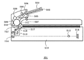
図5は、図3に示したスキャナ部301の構成を説明する断面構成図である。
FIG. 5 is a cross-sectional configuration diagram illustrating the configuration of the
図5において、原稿503上の情報は原稿読み取り装置519の露光部513に対して原稿503を相対的に移動させながら読み取られる。
In FIG. 5, information on the original 503 is read while moving the original 503 relative to the
原稿503は原稿トレイ502にセットされる。原稿給紙ローラ504は分離パッド505と対になっていて、原稿503を一枚ずつ搬送する。そして、搬送された原稿503は中間ローラ506で装置内に送られ、大ローラ508と第1従動ローラ509によって搬送され、さらに大ローラ508と第2従動ローラ510とによって搬送される。
The
大ローラ508と第2従動ローラ510とで搬送された原稿503は、流し読み原稿ガラス512と原稿ガイド板517との間を通り、ジャンプ台518を経由して、大ローラ508と第3従動ローラ511とにより搬送される。大ローラ508と第3従動ローラ511とにより搬送された原稿503は原稿排紙ローラ対507により装置外に排出される。なお流し読み原稿ガラス512と原稿ガイド板517との間では原稿503は原稿ガイド板517によって流し読みガラス512に接触する形で搬送される。
The original 503 conveyed by the
原稿503は流し読み原稿ガラス512上を通過する際に、流し読み原稿ガラス512に接している面が露光部513によって露光される。その結果得られる原稿503からの反射光がミラーユニット514に伝達される。伝達された反射光はレンズ515を通過して集光されCCDセンサ部516にて電気信号に変換される。
When the original 503 passes over the flow reading
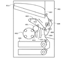
図6は、図3に示したプリンタ部302の構成を説明する断面構成図である。本例は、1ドラム式の感光ドラムに露光された静電潜像を各色トナーで順次重ね転写することフルカラー画像を形成する。なお、プリンタエンジンは、1ドラム方式に限らず、4ドラム方式でカラー画像を形成するプリンタエンジンを備えるプリンタ部302であってもよい。なお、図6に示す給紙部は、2つのカセットを備える例である。なお、これらのカセット以外にオプションカセットを重ねて装着可能としてもよい。
FIG. 6 is a cross-sectional configuration diagram illustrating the configuration of the
図6において、感光ドラム601は一次帯電気611により特定の極性電位に帯電処理され、図示しない露光手段によって612の矢印の位置が露光される。このようにして第一の色成分に対応した静電潜像が形成される。その後、602の四つある現像機中の一つの現像機を使用して現像される。
In FIG. 6, a
中間転写ベルト603は矢印の方向に駆動され、感光ドラム上に形成された第一の色成分画像が、感光ドラムと中間転写ベルトの接合部分を通る過程で一次転写ローラ610によって形成された電界によって中間転写ベルトに転写される。
The
そして、中間転写ベルトに転写を終えた感光ドラムの表面はクリーニング装置604によって清掃される。この処理を順次繰り返し、四色の画像を中間転写ベルトに重ね合わせて、カラー画像を形成する。単色の画像を形成する場合は一度だけ転写処理を行う。
Then, the surface of the photosensitive drum that has been transferred to the intermediate transfer belt is cleaned by the
そして、中間転写ベルト603に転写された画像は二次転写ローラ609部分でカセット605より給紙された用紙に印刷される。画像が印刷された用紙は定着機606で加熱され定着される。そして、定着後、排紙口614まで用紙が搬送され機外に排出される。両面印刷を行う場合は、反転パス608をとおって用紙を循環させ、印刷処理を繰り返す。
Then, the image transferred to the
図7は、図3に示したフィニッシャ部304の構成を説明する断面構成図である。
FIG. 7 is a cross-sectional configuration diagram illustrating a configuration of the
図7において、排紙ビン701、702、703を備えている。プリンタ部から搬送された用紙は705から給紙され、排紙ビン701に出力する場合はパス706に用紙を導き排紙ビン701に排出する。また、排紙ビン702に出力する場合はパス707に用紙を導き排紙ビン702に排出する。
In FIG. 7,
排紙ビン703に出力する場合は排紙ビン702と703を上方に移動させパス707と排紙ビン703の高さをあわせた後に用紙を排出する。また、排紙ビン704は製本専用の排紙ビンであり、パス709から製本ユニット708に用紙が導かれ、708内で製本処理が行われてから排紙ビン704に排出される。
When outputting to the
図8は、図3に示したMFP300のソフトモジュールの構成を説明するブロック図である。 FIG. 8 is a block diagram illustrating the configuration of the software module of MFP 300 shown in FIG.
図8において、800は表示操作部を制御するUI制御部である。801はコピーアプリケーション部で、UI制御部800からの指示を受け、コピー動作を実行する。
In FIG. 8,
802は送信アプリケーション部で、UI制御部800からの指示を受け、送信動作を実行する。803はBOXアプリケーション部で、ボックス画面からのスキャン、プリントを実行する。
A
また、805はPDLアプリケーション部で、ネットワークアプリケーション804からのPDLプリントデータをうけPDLプリントジョブを投入する。
A
806は共通インタフェースで、機器制御部分の機器依存部分を吸収する。807はジョブマネージャで、共通インタフェース806から受け取ったジョブ情報を整理し、下位層のドキュメント処理部に伝達する。
ここで、ドキュメント処理部は以下のマネージャ部から構成される例を示す。 Here, an example in which the document processing unit includes the following manager unit will be described.
例えばローカルコピーであればスキャンマネージャ808とプリントマネージャ809がドキュメント処理部として機能する。
For example, in the case of local copy, the
また、リモートコピーの送信ジョブ、あるいは送信ジョブであればスキャンマネージャ808とファイルストアマネージャ810がドキュメント処理部として機能する。
In the case of a remote copy transmission job or a transmission job, the
また、リモートコピーの受信ジョブであればファイルリードマネージャ811とプリントマネージャ809、PDLプリントではPDLマネージャ812とプリントマネージャ812がドキュメント処理部として機能する。ここで、PDLとはLIPSやPostScriptなどが好例である。
In the case of a remote copy reception job, the file read
各ドキュメントマネージャ間の同期とり、および各種画像処理を行うイメージマネージャ813への画像処理の依頼はシンクマネージャ814を介して行う。さらに、スキャン、プリント時の画像処理や画像ファイルの格納はイメージマネージャ813が行う。なお、以下、アプリケーション部をAPPL部と略記する。
The
また、解析アプリ815は、PDLAPPL部805から出力されたジョブファイルを解析し、解析、編集を行って共通インタフェースにジョブを投入する
図9は、本実施形態を示す画像処理装置で処理可能なジョブの実体となるデータの内部構造を示す図である。
Also, the
図9において、これらのジョブファイルとデータは、図8に示したUI制御部800もしくはネットワークアプリケーション804からジョブを実行する指示が来た場合に、機器内のAPPL部801、802、803、805により生成する。
9, these job files and data are obtained by the
例えばコピージョブでは、ディスプレイ203から入力された設定がコピーAPPL部801に通知される。そして、通知された情報から生成し、PDLジョブではネットワークAPPL部804から通知された情報をもとにPDLAPPL部805が生成する。
For example, in a copy job, the setting input from the
ジョブの実体は、属性ID901、904、910、属性値サイズ902、905、911および属性値903、906、912の組を複数連続して持つことによって表されている。
The job entity is represented by having a plurality of sets of
また、ジョブがデータを含む場合は、属性ID907としてデータを表す値、属性値909としてファイル名の属性値サイズ908、属性値としてドキュメントデータを保持しているデータファイル913のファイル名を保持している。
If the job includes data, the
また、属性値909中には、データファイル913のフォーマット(使用されているPDLなど)、コピー部数、カセット段、フィニッシング処理指定などが含まれる。 Further, the attribute value 909 includes the format of the data file 913 (PDL used), the number of copies, the cassette stage, the finishing process designation, and the like.
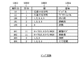
図10は、図9に示したジョブの実体となるデータの内部構造の要部詳細を示す図である。本例は、データの内部構造中のジョブ情報属性の一例を示したものである。 FIG. 10 is a diagram showing the details of the main part of the internal structure of the data as the job entity shown in FIG. This example shows an example of job information attributes in the internal structure of data.
図10において、属性ID1001は、属性のID番号を示している。型ID1002はIDの型(サイズ)を表しており、「1」なら不定長、「2」なら1バイトのように決まっている。型ID1002が「11」の場合、値1003は、「0〜7015,0から9920」の値となる。
In FIG. 10, an
値1003は取り得る値を示している。意味1004に示すような意味をもっている。この表に示したのは一例であり、この他にも様々な属性が存在する。これらの値を図9に示した属性ID、属性サイズID、属性値に設定されることによりジョブを形成する。なお、本実施形態では、意味1004として、ジョブ名、アプリケーション名、カセット段、排紙段、部数、画像サイズ、移動量、両面、とじ位置等の例を示す。なお、このアプリケーション名は、特定のアプリケーションに対応づけられた名が設定される。
A
図11は、本実施形態を示す画像処理装置でアプリケーション毎に設定できるデフォルト設定属性テーブル(以下、属性テーブルと略記する)の一例を示す図である。ここで、アプリケーションとは、クライアント側のユーザにより実行される特定のアプリケーションに対応付けられるアプリケーションである。また、アプリケーション毎に設定できるデフォルト設定属性テーブルは、CPU201により作成されて、図2に示したDISK211に登録される。
FIG. 11 is a diagram showing an example of a default setting attribute table (hereinafter abbreviated as attribute table) that can be set for each application in the image processing apparatus according to the present embodiment. Here, the application is an application associated with a specific application executed by a user on the client side. A default setting attribute table that can be set for each application is created by the
本実施形態では、特定のアプリケーションとは、例えば領収書アプリケーション、文書作成アプリケーション、プレゼンテーションアプリケーション、表計算アプリケーション、作図アプリケーション等である。なお、他のデータ処理を行うアプリケーションであっても差し支えない。 In the present embodiment, the specific application is, for example, a receipt application, a document creation application, a presentation application, a spreadsheet application, a drawing application, or the like. An application that performs other data processing may be used.
図11において、属性ID1101は、「デフォルト」に設定可能な属性を示しおり、この例では、意味1104に対応するように、MFPが使用するカセット段、使用する排紙段、部数、移動量、両面、とじ位置の属性をデフォルト設定可能としている。なお、設定可能な対象は、MFPの画像処理に伴う条件として設定可能なものであれば、これらに限定されるものではない。
In FIG. 11, an
状態1102は属性の設定状況を示し、「デフォルト」の設定、「専用」の設定、「OFF」の設定、「例外」の設定の四つの状態を持つことができる例である。ここで、四つの状態とは、コントローラ101が属性管理テーブルに記憶された適用情報として機能する。
A
従って、コントローラ101は、これら四つの状態に基づいて、印刷ジョブにより指定される印刷属性に代えて、属性テーブルに登録された属性情報に基づいて印刷ジョブを出力するように資源である複数の給紙部を制御する。
Therefore, based on these four states, the
なお、「デフォルト」の設定となっている属性は、図9に示したジョブの属性の中に一致する属性が存在した場合に、この値に置き換えることを意味している。 Note that the attribute set to “default” means that if there is a matching attribute among the job attributes shown in FIG. 9, this value is replaced.
また、状態1102が「専用」設定となっている属性は、図11に示す例では、カセット段に対応するので、カセット段はリストが関連付けられたアプリケーション(例えば領収書アプリケーション)しか使用できないことを示している。つまり、図11に示す例では、属性ID1101が「100」は、状態1102が「専用」であるため、意味1104がカセット段については、アプリケーションの値に依存せず、値1103「1」に強制設定されることを意味する。
Further, the attribute whose
したがって、領収書アプリケーションがDISK211内の属性テーブルに登録されている場合、アプリケーション側でカセット段を誤ってカセットC2を指定していてもコントローラ101は、カセット段の指定をカセットC1とする。
Therefore, when the receipt application is registered in the attribute table in the DISK 211, the
これにより、領収書アプリケーションに専用の用紙を割り当てて、カセットC1に収容している場合、領収書アプリケーションのファイルは、必ずカセットC1の用紙を選択する制御が実行される。 As a result, when a dedicated sheet is allocated to the receipt application and stored in the cassette C1, the receipt application file is always controlled to select the sheet in the cassette C1.
さらに、図11に示す属性テーブル中の状態1102が「OFF」設定となっている属性は、デフォルト設定が行われていないことを示している。
Furthermore, an attribute whose
さらに、状態1102が、「例外」の設定となっている属性は、アプリケーションで属性が設定された場合に、デフォルトを無視することを意味している。
Furthermore, an attribute whose
例えば、領収書アプリケーションで作成されたファイルをアプリケーションに割り付けた専用の用紙に印刷する本印刷に代えて、「試し印刷」をする。このような場合(アプリに割り当てられた「専用」の用紙を使用しない場合)に有効な設定となる。これにより、カセット段の制御において、領収書アプリケーションにおいて、カセットC1が専用として登録されていても、カセットC1とは異なる、アプリケーション側の指定に対応するカセットC2等を選択可能となる。そして、カセットC2に収納された専用用紙以外の安価な普通紙で試し印刷可能となる。 For example, “trial printing” is performed instead of the main printing in which a file created by the receipt application is printed on a dedicated sheet assigned to the application. This setting is effective in such a case (when “dedicated” paper assigned to the application is not used). Thereby, in the cassette stage control, even if the cassette C1 is registered as dedicated in the receipt application, it is possible to select a cassette C2 or the like corresponding to the designation on the application side, which is different from the cassette C1. Then, trial printing can be performed with inexpensive plain paper other than the dedicated paper stored in the cassette C2.
図11に示すテーブル例では、排紙段の属性と両面の属性とがデフォルト設定に割り当てられている。 In the example of the table shown in FIG. 11, the attributes of the paper discharge stage and the attributes of both sides are assigned to the default settings.
このため、デフォルト設定属性テーブルに関連付けられたアプリケーションから投入されたジョブでは、排紙段属性と両面属性の属性値には必ず「2」を使用することを意味する。また、他の属性値が設定されていたり、属性そのものが設定されていなくても、必ず「2」に変更する。 For this reason, in a job submitted from an application associated with the default setting attribute table, it means that “2” is always used as the attribute value of the paper discharge stage attribute and the double-sided attribute. Even if another attribute value is set or the attribute itself is not set, the value is always changed to “2”.
また、図11に示す例では、カセット段の属性に「専用」が割り当てられており、デフォルト設定属性テーブルに関連付けられたアプリケーションから投入されたジョブでは、カセット段の属性は必ず「1」を使用することを意味する。この際、カセット段の属性に他の属性値が設定されていたり、属性そのものが設定されていなくても、必ず「1」に変更する。 In the example shown in FIG. 11, “dedicated” is assigned to the attribute of the cassette stage, and “1” is always used as the attribute of the cassette stage in a job submitted from an application associated with the default setting attribute table. It means to do. At this time, even if another attribute value is set for the attribute of the cassette stage or the attribute itself is not set, it is always changed to “1”.
また、状態1102が「専用」に設定された属性の属性値は、デフォルト設定属性テーブルに関連付けられたアプリケーション以外では使用することができないことを意味する。
Further, an attribute value of an attribute whose
これにより、例えば意味1104が「カセット段」の属性に対して、状態1102で「専用」が設定されている場合、対応づけて登録された特定アプリケーションは、値1103の「値」で特定されるカセットが選択される。そして、対応づけて登録された特定アプリケーション以外では、値1103の「値」で特定されるカセットを選択することを不可とすることができる。
Thus, for example, when “dedicated” is set in the
この結果、このリストに関連付けられていないアプリケーションでは、カセット段の属性の値1103に「1」を使用できなくなる。
As a result, an application that is not associated with this list cannot use “1” as the cassette
また、登録された特定のアプリケーションに対して、本印刷とは異なる、試し印刷を行う場合を考える。このとき、状態1102が「専用」で意味1104が「試し印刷」となっている属性に対して、値1103に「1」という値で設定される。
Also, consider a case where trial printing, which is different from actual printing, is performed for a registered specific application. At this time, the
この場合、カセット段と両面との設定は、デフォルトの値に変更されることがないということを示している。つまり、アプリケーション側の設定が優先する。 In this case, it is indicated that the setting of the cassette stage and the double side is not changed to the default value. That is, the setting on the application side has priority.
この例外設定は試し印刷をするような場合に、アプリ専用の用紙を使わず、普通の用紙に印刷したい場合に有効な設定となる。 This exception setting is effective when you want to print on plain paper instead of using application-dedicated paper when performing trial printing.
図12(A)〜図12(D)は、図1に示した操作部106によるアプリケーションごとのデフォルト設定方法を説明する操作画面の一例を示す図である。
FIGS. 12A to 12D are diagrams illustrating an example of an operation screen for explaining a default setting method for each application by the
通常、待機状態では、操作部106の液晶表示部401に図12(A)に示す標準画面が表示されている。
Normally, in the standby state, the standard screen shown in FIG. 12A is displayed on the liquid
そして、標準画面は、操作画面エリア1201とフリーエリア1202があり、操作画面エリア1201にはコピー等の動作設定や状態を確認するための情報が表示される。
The standard screen includes an operation screen area 1201 and a
また、フリーエリア1202はその他の情報を表示することが可能となっている。
The
なお、テンキー405のボタン群の中に含まれるユーザ設定ボタンを押下すると、操作部106の液晶表示部401の画面表示は、図12(B)に示す画面表示に切り替わる。
When a user setting button included in the button group of the
図12(B)において、1203は様々な設定を行うためのボタンを表示する設定登録画面である。ボタン1204はデフォルト管理設定ボタンであり、このボタンを押下すると、操作部106の液晶表示部401の画面表示は、図12(C)に示す画面に切り替わる。
In FIG. 12B,
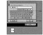
図12(C)において、キーボード画面1204が表示されるので、ここからアプリケーションの名前を登録する。この例では「領収書アプリ」というアプリケーション名称を登録している。なお、MFPのコントローラ101は、漢字変換処理アプリケーションを記憶しているので、キーボード画面1204に文字データを入力することで、漢字変換処理された文字列が表示される。
In FIG. 12C, a keyboard screen 1204 is displayed, and the name of the application is registered from here. In this example, an application name “receipt application” is registered. Since the
ここで、アプリケーション名等の登録が終了したら、OKボタン1205を押下する。OKボタン1205を押下すると、操作部106の液晶表示部401の画面表示は、図12(D)に示す画面に切り替わる。
Here, when registration of the application name and the like is completed, an
図12(D)において、画面が表示されフリーエリア1202にフォルダ1206が表示される。この時に、図11に示した状態1102が全て「OFF」、値が全てないデフォルト設定属性テーブルがDISK211上に生成される。つまり、ユーザの設定が反映されていない初期設定状態のデフォルト設定属性テーブルが生成される。
In FIG. 12D, a screen is displayed and a
この操作を繰り返すと、フリーエリア1202に複数のフォルダが表示され、それぞれに対応したデフォルト設定属性テーブルがDISK211に生成される。
When this operation is repeated, a plurality of folders are displayed in the
図13は、図12に示したアプリケーション登録処理で作成されるファイル名一覧を示す図である。 FIG. 13 is a diagram showing a list of file names created by the application registration process shown in FIG.
上述したように生成されたテーブルは、図13に示すようなファイル名で管理され、対応したファイル名のファイルをDISK211から取り出すことでどのようなデフォルト属性が設定されているかを確認することができる。 The table generated as described above is managed with a file name as shown in FIG. 13, and it is possible to confirm what default attribute is set by taking out a file with a corresponding file name from the DISK 211. .
図14(A)〜図14(G)は、図12に示したデフォルト設定属性テーブルに対する属性値設定画面の一例を示す図である。ユーザは、図14(A)〜図14(G)に示す表示画面を介して、上述したように生成したデフォルト設定属性テーブルに値を設定する。 FIGS. 14A to 14G are diagrams illustrating an example of an attribute value setting screen for the default setting attribute table illustrated in FIG. The user sets values in the default setting attribute table generated as described above via the display screens shown in FIGS. 14 (A) to 14 (G).
例えば領収書アプリには、図3に示したカセットC1を必ず使用させたい場合は、システム状況ボタン1207を押下すると、図12(A)に示した標準画面から図14の(A)に示す属性設定画面が表示される。なお、図14に示す画面上には、MFPが装備している給紙手段、排紙手段がリソースに応じたアイコンで表示され、各アイコンは、コントローラ101内でドラッグ可能に内部的に制御されている。
For example, if the receipt application always wants to use the cassette C1 shown in FIG. 3, when the system status button 1207 is pressed, the attributes shown in FIG. 14A from the standard screen shown in FIG. The setting screen is displayed. On the screen shown in FIG. 14, the paper feed unit and paper discharge unit provided in the MFP are displayed as icons corresponding to the resources, and each icon is internally controlled to be draggable within the
図14(A)において、カセット番号1401中から、特定アプリケーションに割り当てるカセットを決定する。そして、表示されるカセットに対応づけされているアイコンをドラッグして、作成されたフォルダアイコンIC1〜IC3にドロップする。これにより、特定アプリケーションとカセットC1〜C4が対応づけられて登録される。
In FIG. 14A, a cassette to be assigned to a specific application is determined from among the
なお、ドラッグ可能な属性は、カセットに限らず、図14(A)に示すように、排紙ビンであってもよい。つまり、カセットや排紙ビンのアイコンをドラッグしてフォルダにドラッグアンドドロップすることが可能になっている。 The draggable attribute is not limited to the cassette, and may be a paper discharge bin as shown in FIG. That is, it is possible to drag and drop the icon of the cassette or the paper discharge bin to the folder.
特に本例では、図14(A)において、カセットアイコン(番号1)をドラッグして、領収書アプリフォルダAF1にドロップする様子を示している。 In particular, in this example, FIG. 14A shows a state where the cassette icon (number 1) is dragged and dropped into the receipt application folder AF1.
この操作を行うと、コントローラ101は、DISK211で管理している領収書アプリに対応したデフォルト設定属性テーブルのカセットを示す情報属性ID100の欄の値を以下のように設定する。つまり、デフォルト設定属性テーブルのカセットを示す情報属性ID100の欄の値をMFPが装備する物理的なカセットC1に対応する「1」に変更して、DISK211に格納される。
When this operation is performed, the
このときにドラッグした属性をフォルダに対応したアプリケーションの「デフォルト」設定とするか、「専用」設定とするか、「例外」設定とするかを設定するための画面が、図14(B)に示すように表示される。 FIG. 14B shows a screen for setting whether the attribute dragged at this time is the “default” setting, the “dedicated” setting, or the “exception” setting of the application corresponding to the folder. Is displayed as shown.
ここで、ユーザが「デフォルト」にする場合はデフォルトボタン1402、専用にする場合は専用ボタン1403、例外にする場合は例外ボタン1404、設定を行わない場合はキャンセルボタン1405を押下する。
Here, the user depresses a
いずれかのボタンを押下すると、コントローラ101が図11に示したデフォルト設定属性テーブルの状態の項目が変更され、DISK211に書き込まれる。
When one of the buttons is pressed, the
また、この際、コントローラ101は、図15に示すデバイス管理テーブルを更新し、カセットやビンなどの部位がどのアプリケーションの専用になったのかを示すデータを書き込む。
At this time, the
図15は、図2に示したDISK211に記憶されるデバイス管理テーブル(DMT)の一例を示す図である。本例は、MFPに装備される給紙リソースと、排紙リソースと割り当てられた専用アプリケーションとの関係が記憶される例である。本実施形態では、MFPのリソースとして、給紙リソースと、排紙リソースに、特定のアプリケーションを対応づけ可能に構成されている例である。なお、特定のアプリケーションに対応付け可能なリソースは、これらに限定されるものではない。 FIG. 15 is a diagram showing an example of a device management table (DMT) stored in the DISK 211 shown in FIG. In this example, the relationship between the paper feed resource installed in the MFP, the paper discharge resource, and the assigned dedicated application is stored. The present embodiment is an example in which a specific application can be associated with a paper feed resource and a paper discharge resource as resources of the MFP. The resources that can be associated with a specific application are not limited to these.
図15において、本テーブルではカセットC1とビンB1が領収書アプリ専用の部品となっていることを示している。つまり、本テーブルもコントローラ101が制御するDISK211に保存され、同様の設定が行われるたびに更新される。
In FIG. 15, this table shows that the cassette C1 and the bin B1 are dedicated parts for the receipt application. That is, this table is also stored in the DISK 211 controlled by the
また、このテーブル上で専用に割り当てられた部分は、他のジョブやアプリケーションでは使用できなくなる。 In addition, the portion assigned exclusively on this table cannot be used by other jobs or applications.
このような設定を終了すると、画面表示は、図14(C)に示す画面表示に切り替わる。 When such setting is completed, the screen display is switched to the screen display shown in FIG.
図14(C)において、1406は、専用に割り当てられたアプリケーション名を表示した状態である。
In FIG. 14C,
次に両面設定を登録する場合の処理について操作画面を使用して説明する。 Next, processing for registering double-sided settings will be described using an operation screen.
図示しないモード設定ボタンを押下すると、画面表示は、図14(D)に示す画面表示に切り替わる。 When a mode setting button (not shown) is pressed, the screen display is switched to the screen display shown in FIG.
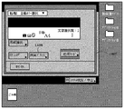
図14(D)は、モード設定画面1407を表示しており、両面の設定を行うために両面プリントボタン1408を押下すると、画面表示は、図14(E)に示す画面表示に切り替わる。
FIG. 14D displays a mode setting screen 1407. When the
図14(E)は、両面プリント種類設定画面1409を表示しており、左右開きボタン1410か上下開きボタン1411を押下し、両面印刷の設定を行った後にOKボタン1412ンを押下する。OKボタン1412を押下すると、画面表示が図14(F)に示す表示画面に切り替わる。
FIG. 14E displays a double-sided print
図14(F)はプリント機能を登録されたアプリケーションに対応付ける登録画面を表示しており、両面ボタン1415が設定されている状態である。
FIG. 14F displays a registration screen for associating the print function with the registered application, and shows a state in which a double-
この両面ボタン1415を任意のフォルダにドラッグアンドドロップすると、コントローラ101がDISK211で管理するデバイス管理テーブルの両面属性の属性値が変更される。
When this double-
また、両面ボタン1415をドロップすると、画面表示が図14(G)に示す属性確認画面に切り替わる。
When the double-
図14(G)に示す属性確認画面で、ユーザが上記プリント機能に対してアプリケーションを対応づけした場合に、その属性の状態を設定する。 When the user associates an application with the print function on the attribute confirmation screen shown in FIG. 14G, the state of the attribute is set.
本例では、属性によって設定できる状態は異なりこの画面ではデフォルトと例外の設定が可能となっている。 In this example, the states that can be set differ depending on the attribute, and the default and exception settings can be made on this screen.
なお、コントローラ101は、デフォルトボタン1416、例外ボタン1417、キャンセルボタン1418のいずれかを設定することにより、デバイス管理テーブルが更新されDISK211に書き込まれる。
The
なお、DISK211に設定した内容を解除したくなった場合は対応するフォルダをごみ箱にドラッグアンドドロップすることで対応するデバイス管理テーブルがDISK211から削除される。また、コントローラ101は、デバイス管理テーブルの中に状態が専用となっているものがある場合は、図15に示した専用フラグがONになっているものをOFFに変更してDISK211に格納する。
When it is desired to cancel the contents set in the DISK 211, the corresponding device management table is deleted from the DISK 211 by dragging and dropping the corresponding folder into the trash box. Also, if there is a device management table that has a dedicated state, the
図16は、本実施形態を示す画像処理装置におけるデータ処理手順の一例を示すフローチャートである。本例は、解析アプリ815による特定のアプリケーションからのジョブが投入力された場合に、デフォルト設定属性テーブルを参照して属性値を変更する処理例である。なお、S1601〜S1612は各ステップを示す。なお、各ステップは、コントローラ101がDISK211等からメモリ202上に制御プログラムをロードして実行することで実現される。
FIG. 16 is a flowchart illustrating an example of a data processing procedure in the image processing apparatus according to the present embodiment. In this example, when a job from a specific application is input by the
なお、ホストからはネットワークを介してネットワークに対応したプロトコルでファイルやデータが送信され、MFPのネットワークアプリケーション部で受信する。 Note that files and data are transmitted from the host via a network using a protocol corresponding to the network, and received by the network application unit of the MFP.
そして、ネットワークアプリケーション部はデータやファイル等の情報受信した後に、機器内アプリケーションに受信した情報をアプリケーション801、802、803、805で適切な図9に示したジョブファイルの形状に整形する。そして、共通インタフェース部806にジョブファイルを投入することでジョブを実行する。
Then, after receiving information such as data and files, the network application unit shapes the information received by the in-device application into an appropriate job file shape shown in FIG. 9 using the
なお、デフォルト設定が行われている場合は、PDLアプリケーションから共通インタフェースに部分にジョブを投入する前に、解析アプリ815にデータを転送しその後共通インタフェース部806にデータを転送する。
If default settings have been made, the data is transferred to the
まず、S1601で、解析アプリ815に投入されたジョブファイルを解析する。そして、コントローラ101は、図10に示したジョブの実体上の属性ID1001が「11」の値1003の文字列と同じ名称を持つファイル名が図11に示した属性テーブル内に存在するかを判断する。ここで、属性ID1001が「11」の値1003の文字列と同じ名称を持つファイル名が属性テーブル中にないと判断した場合は、S1602でデフォルト設定を無しとする。ここで、MFPのDISK211に登録済みと未登録のアプリケーションとが識別されて、以後の属性設定処理が切り替わる。
First, in step S1601, the job file input to the
そして、S1604で、コントローラ101は、図15に示すデバイス管理テーブルDMT中の専用フラグ1502がONになっている属性がジョブファイルの中に存在するか判断する。ここで、専用フラグ1502がONになっている属性がないと判断した場合は、S1606へ進む。ここで、特定のアプリケーションと、MFPのリソースに対する属性設定が判断される。
In step S1604, the
一方、S1604で、専用フラグ1502がONになっている属性があると判断した場合は、S1605で、図15に示した専用フラグ1502でONに指定されている属性の属性値と一致しない値に変更する。
On the other hand, if it is determined in S1604 that there is an attribute for which the
これにより、図15の例ではデフォルト設定の行われていないアプリケーションからのジョブでは属性ID1504が「101」の属性値1506は「1」以外の値、属性ID1504が「102」の属性値1506は「3」以外の値に変更されることになる。つまり、領収書アプリケーションとアプリケーションB以外のアプリケーションは、上記のようにデバイス管理テーブルに登録された属性値と異なる値に設定される。
As a result, in the example of FIG. 15, in a job from an application for which default setting is not performed, the
一方、S1601で、図10に示した属性ID1001が「11」の値1003の文字列と同じ名称を持つファイル名が図13で示したデフォルト設定属性テーブル内に存在する場合は、S1603で、デフォルト設定をありに設定する。そして、S1606へ進む。
On the other hand, if a file name having the same name as the character string of the
そして、S1606で、コントローラ101は、デフォルト設定が有りかなしかを判断する。ここで、デフォルト設定なしと判断した場合は、S1611へ進む。
In step S1606, the
一方、S1606で、コントローラ101がデフォルト設定ありと判断した場合は、S1607で、ジョブファイルに図11に示した属性テーブル中の状態1102で「例外」と設定された属性と一致する属性があるかどうかを判断する。ここで、設定された属性と一致する属性がないと判断された場合は、対応する属性に変更する(S1608)。
On the other hand, if the
これは、登録された特定アプリケーションの属性を故意に解除させる要求がある場合に適応するために判断する処理である。これにより、領収書アプリケーションで登録されたカセットC1以外のカセットC2等を選択させるための判断である。 This is a process for making a determination in order to adapt to a request for deliberately releasing the attribute of the registered specific application. This is a determination for selecting a cassette C2 other than the cassette C1 registered in the receipt application.
一方、S1607で、「例外」が設定された属性と一致する属性がジョブファイルに存在すると判断した場合は、S1609へ進む。 On the other hand, if it is determined in S1607 that the job file has an attribute that matches the attribute for which “ exception” is set, the process advances to S1609.
次に、S1609で、ジョブファイル中に、デフォルト設定属性テーブルで「専用」に設定された属性と一致するものがあるかどうかを判断する。ここで、「専用」に設定された属性と一致するものがないと判断した場合は、S1611へ進む。 Next, in S160 9, the in di Yobufairu to determine whether the default configuration attribute table for a match with the set attribute to "only". If it is determined that no attribute matches the attribute set to “ dedicated”, the process advances to step S1611.
一方、S1609で、「専用」に設定された属性と一致するものがあると判断した場合は、S1610で、コントローラ101は、生成されたジョブの属性値を、図11に示したデフォルト設定属性テーブルで設定された属性値に変更する。また、ジョブファイル中に属性が存在しなければ、属性の設定を追加する。これにより、MFPのDISK211に特定アプリケーションに対応づけて登録された属性値と異なる属性値をジョブの属性値が示していても、属性テーブルに一致する属性値に書き換えられる。こうすることで、ユーザが領収書アプリケーションに割り当てているカセットC1から専用の用紙を給紙する。そして、S1611で、ジョブファイルを共通インタフェース806に投入して、本処理を終了する。
On the other hand, in S1609, if it is determined that there is also to coincide with the set attribute to "only", in S1610, the
このように本実施形態に示す画像処理装置は、以下のように特徴的な機能を備える。 As described above, the image processing apparatus according to the present embodiment has the following characteristic functions.
本実施形態に示す画像処理装置である図1に示すMFPは、複数の資源から選択されるいずれかの資源を使用して画像処理を行う。ここで、資源とは、複数の給紙部(カセットC1〜C4)を備える給紙手段または複数の排紙部に対応する。 The MFP shown in FIG. 1, which is the image processing apparatus shown in the present embodiment, performs image processing using any resource selected from a plurality of resources. Here, the resource corresponds to a paper feed unit including a plurality of paper feed units (cassettes C1 to C4) or a plurality of paper discharge units.
この場合において、図8に示すように特定機能処理を実行するアプリケーションファイルから印刷ジョブを生成する生成モジュールとしてのアプリケーションを記憶して、これらのアプリケーションをコントローラ101が実行する。これにより、入力されるアプリケーションに対応した印刷ジョブを生成する。
In this case, as shown in FIG. 8, applications as generation modules that generate print jobs from application files that execute specific function processing are stored, and the
また、DISK211は、組込可能なアプリケーション毎に使用する前記複数の資源から選択すべき資源を特定する属性情報を記憶する属性テーブル(図11、図15に示すテーブル)を記憶する。 The DISK 211 stores an attribute table (table shown in FIGS. 11 and 15) that stores attribute information for specifying a resource to be selected from the plurality of resources used for each embeddable application.
そして、コントローラ101は、印刷ジョブから特定されるアプリケーションが属性テーブルに登録されているかどうかを判断する図16に示す判断機能を備える。
The
そして、コントローラ101は、属性テーブルに登録されていると判断した場合、印刷ジョブにより指定される印刷属性に代えて、属性テーブルに登録された属性情報に基づいて前記印刷ジョブを出力するように前記資源の選択を制御する。
When the
一方、属性テーブルに登録されていないと判断した場合、印刷ジョブにより指定される印刷属性と登録されている属性情報とを比較する。そして、コントローラ101が属性情報に一致する印刷属性を変更して、印刷ジョブを出力するようにいずれかのカセットの選択を制御する。
On the other hand, if it is determined that it is not registered in the attribute table, the print attribute designated by the print job is compared with the registered attribute information. Then, the
また、コントローラ101は、属性管理テーブルに記憶された図11に示すような適用情報に基づいて、印刷ジョブにより指定される印刷属性に代える。そして、属性テーブルに登録された属性情報に基づいて印刷ジョブを出力するようにいずれかのカセットを選択すべきかどうかを決定する。
Further, the
以上述べたように、各アプリケーション毎のデフォルト設定を登録可能とし、ジョブを投入したアプリケーション毎に異なるデフォルト設定が行えるようになる。 As described above, the default settings for each application can be registered, and different default settings can be performed for each application that has submitted a job.
さらには、各アプリケーション毎の専用設定を可能とすることで、例えば領収証専用の用紙を設定したカセットC1は領収書専用のアプリケーション以外では使用されないように設定できる。これにより、異なるアプリからの印刷出力を、誤って領収書専用の用紙に印刷してしまうようなミスを無くすことが可能になる。 Furthermore, by making it possible to make dedicated settings for each application, for example, the cassette C1 on which paper for receipt is set can be set to be used only by applications dedicated to receipt. As a result, it is possible to eliminate a mistake that a print output from a different application is erroneously printed on a receipt-dedicated sheet.
また、本実施形態によれば、クライアント側のドライバ設定には左右されることなく、登録したアプリケーションに対して設定されている属性情報に従い、アプリケーションから生成される印刷ジョブの印刷属性を変更する。これにより、従来であれば、ドライバ設定を変更する負担が不要となり、ネットワーク管理者の負担も軽減される。 Further, according to the present embodiment, the print attribute of the print job generated from the application is changed according to the attribute information set for the registered application, regardless of the driver setting on the client side. Thus, conventionally, the burden of changing the driver setting is not necessary, and the burden on the network administrator is reduced.
また、カセットの環境を変更しても、MFP内部の属性情報を変更することで対応できるため、システム環境に適応した印刷ジョブ処理を実現できる。 Also, even if the cassette environment is changed, it can be handled by changing the attribute information inside the MFP, so that print job processing adapted to the system environment can be realized.
また、アプリケーションに登録する印刷属性とを簡単な操作で登録あるいは削除できるため、アプリケーションに適応した印刷ジョブ環境を自在に構築できる。 In addition, since print attributes to be registered in the application can be registered or deleted with a simple operation, a print job environment adapted to the application can be freely constructed.
〔第2実施形態〕
上記第1実施形態では、特定のアプリケーションに対応づけて登録されたリソース資源を利用して、コントローラ101が図16に示す制御手順に基づいて印刷制御を行う場合について説明した。この場合、コントローラ101は、属性テーブルは、組込可能なアプリケーション毎に使用する複数のカセットから選択すべきカセットを特定する属性情報に設定可能な印刷モードを登録可能としている。
[Second Embodiment]
In the first embodiment, the case has been described in which the
一方、特定のアプリケーションとして、例えば領収書アプリケーションでは、印刷する項目として、日付、会社名、通し番号等のスタンプ情報を利用したい場合がある。 On the other hand, as a specific application, for example, a receipt application, there is a case where it is desired to use stamp information such as a date, a company name, and a serial number as an item to be printed.
そこで、図12に示した特定アプリケーションの登録時に、MFPで選択可能な応用スタンプ情報を、図12で示した登録方法と同様に登録させる。そして、ユーザが領収書アプリケーションを利用して印刷する場合の連番、日付、宛名等を自動印刷できるように制御してもよい。 Therefore, when registering the specific application shown in FIG. 12, application stamp information selectable by the MFP is registered in the same manner as the registration method shown in FIG. Then, control may be performed so that the serial number, date, address, etc. when the user prints using the receipt application can be automatically printed.
図17は、本発明の第2実施形態を示す画像処理装置による応用モード割付処理動作を説明する図である。 FIG. 17 is a diagram for explaining the application mode assignment processing operation by the image processing apparatus showing the second embodiment of the present invention.
図17(A)において、1700は操作画面で、MFPで実行可能な応用モード画面に対応する。本例では、応用モードとして、表示/台紙、製本、移動、とじしろ、合成、ページ番号印字、スタンプ日付印字等が設定可能な例である。 In FIG. 17A, reference numeral 1700 denotes an operation screen corresponding to an application mode screen that can be executed by the MFP. In this example, display / mounting, bookbinding, movement, margin, composition, page number printing, stamp date printing, and the like can be set as application modes.
具体的には、ユーザは、本画面において、既にDISK112に登録したアプリケーションのフォルダに応用モードのアイコンを登録したアプリケーションのフォルダに対してドラッグアンドドロップする。 Specifically, on this screen, the user drags and drops the application mode icon in the application folder already registered in the DISK 112 to the application folder.
これにより、例えば領収書アプリケーションにスタンプ日付印字の応用モードが登録されていることを、図17(C)に示す参照テーブルからコントローラ101が判断することができる。
Accordingly, for example, the
この場合、コントローラ101は、領収書アプリケーションで作成されたジョブに従い、生成された領収金額、会社名、に加えて、スタンプ機能で生成された日付や通し番号を指定された位置に合わせて印刷することができる。これにより、図17(B)に示す領収書が指定されたカセットC1から給紙される用紙上に印刷される。
In this case, in accordance with the job created by the receipt application, the
なお、通し番号は、上述した試し印刷時には、有効とはならないようにコントローラ101により制御されている。
Note that the serial number is controlled by the
〔第3実施形態〕
また、上記実施形態では、1台のMFPを使用して特定のアプリケーションを実行したファイルを処理する場合について説明した。
[Third Embodiment]
In the above-described embodiment, a case has been described in which a single application is used to process a file in which a specific application is executed.
しかしながら、事務上では、複数のMFPを使用して、同一の業務を処理する場合もある。このような場合には、各MFPの通信機能を利用して、最新の管理情報を共有する。これにより、例えば領収書印刷時に、いずれのMFPから印刷要求を行っても、連番で正しい通し番号を領収書印刷時に合わせて印刷するように各MFPのコントローラ101が領収書印刷処理を連携可能に制御することが望ましい。
However, in office work, a plurality of MFPs may be used to process the same job. In such a case, the latest management information is shared using the communication function of each MFP. This enables the
〔第4実施形態〕
以下、図18に示すメモリマップを参照して本発明に係る情報処理装置で読み取り可能なデータ処理プログラムの構成について説明する。
[Fourth Embodiment]
The configuration of a data processing program that can be read by the information processing apparatus according to the present invention will be described below with reference to the memory map shown in FIG.
図18は、本発明に係る情報処理装置で読み取り可能な各種データ処理プログラムを格納する記憶媒体のメモリマップを説明する図である。 FIG. 18 is a diagram for explaining a memory map of a storage medium for storing various data processing programs readable by the information processing apparatus according to the present invention.
なお、特に図示しないが、記憶媒体に記憶されるプログラム群を管理する情報、例えばバージョン情報,作成者等も記憶され、かつ、プログラム読み出し側のOS等に依存する情報、例えばプログラムを識別表示するアイコン等も記憶される場合もある。 Although not particularly illustrated, information for managing a program group stored in the storage medium, for example, version information, creator, etc. is also stored, and information depending on the OS on the program reading side, for example, a program is identified and displayed. Icons may also be stored.
さらに、各種プログラムに従属するデータも上記ディレクトリに管理されている。また、各種プログラムをコンピュータにインストールするためのプログラムや、インストールするプログラムが圧縮されている場合に、解凍するプログラム等も記憶される場合もある。 Further, data depending on various programs is also managed in the directory. In addition, a program for installing various programs in the computer, and a program for decompressing when the program to be installed is compressed may be stored.
本実施形態における図16に示す機能が外部からインストールされるプログラムによって、ホストコンピュータにより遂行されていてもよい。そして、その場合、CD−ROMやフラッシュメモリやFD等の記憶媒体により、あるいはネットワークを介して外部の記憶媒体から、プログラムを含む情報群を出力装置に供給される場合でも本発明は適用されるものである。 The functions shown in FIG. 16 in this embodiment may be performed by the host computer by a program installed from the outside. In this case, the present invention is applied even when an information group including a program is supplied to the output device from a storage medium such as a CD-ROM, a flash memory, or an FD, or from an external storage medium via a network. Is.
以上のように、前述した実施形態の機能を実現するソフトウエアのプログラムコードを記録した記憶媒体を、システムあるいは装置に供給する。そして、そのシステムあるいは装置のコンピュータ(またはCPUやMPU)が記憶媒体に格納されたプログラムコードを読出し実行することによっても、本発明の目的が達成されることは言うまでもない。 As described above, the storage medium storing the software program code for realizing the functions of the above-described embodiments is supplied to the system or apparatus. It goes without saying that the object of the present invention can also be achieved by the computer (or CPU or MPU) of the system or apparatus reading and executing the program code stored in the storage medium.
この場合、記憶媒体から読み出されたプログラムコード自体が本発明の新規な機能を実現することになり、そのプログラムコードを記憶した記憶媒体は本発明を構成することになる。 In this case, the program code itself read from the storage medium realizes the novel function of the present invention, and the storage medium storing the program code constitutes the present invention.
従って、プログラムの機能を有していれば、オブジェクトコード、インタプリタにより実行されるプログラム、OSに供給するスクリプトデータ等、プログラムの形態を問わない。 Therefore, as long as it has the function of the program, the form of the program such as an object code, a program executed by an interpreter, or script data supplied to the OS is not limited.
プログラムを供給するための記憶媒体としては、例えばフレキシブルディスク、ハードディスク、光ディスク、光磁気ディスク、MO、CD−ROM、CD−R、CD−RW、磁気テープ、不揮発性のメモリカード、ROM、DVDなどを用いることができる。 As a storage medium for supplying the program, for example, a flexible disk, hard disk, optical disk, magneto-optical disk, MO, CD-ROM, CD-R, CD-RW, magnetic tape, nonvolatile memory card, ROM, DVD, etc. Can be used.
この場合、記憶媒体から読出されたプログラムコード自体が前述した実施形態の機能を実現することになり、そのプログラムコードを記憶した記憶媒体は本発明を構成することになる。 In this case, the program code itself read from the storage medium realizes the functions of the above-described embodiments, and the storage medium storing the program code constitutes the present invention.
その他、プログラムの供給方法としては、クライアントコンピュータのブラウザを用いてインターネットのホームページに接続する。そして、該ホームページから本発明のコンピュータプログラムそのもの、もしくは、圧縮され自動インストール機能を含むファイルをハードディスク等の記録媒体にダウンロードすることによっても供給できる。また、本発明のプログラムを構成するプログラムコードを複数のファイルに分割し、それぞれのファイルを異なるホームページからダウンロードすることによっても実現可能である。つまり、本発明の機能処理をコンピュータで実現するためのプログラムファイルを複数のユーザに対してダウンロードさせるWWWサーバやftpサーバ等も本発明の請求項に含まれるものである。 As another program supply method, a browser on a client computer is used to connect to an Internet home page. Then, the computer program itself of the present invention or a compressed file including an automatic installation function can be downloaded from the homepage by downloading it to a recording medium such as a hard disk. It can also be realized by dividing the program code constituting the program of the present invention into a plurality of files and downloading each file from a different homepage. That is, a WWW server, an ftp server, and the like that allow a plurality of users to download a program file for realizing the functional processing of the present invention on a computer are also included in the claims of the present invention.
また、本発明のプログラムを暗号化してCD−ROM等の記憶媒体に格納してユーザに配布し、所定の条件をクリアしたユーザに対し、インターネットを介してホームページから暗号化を解く鍵情報をダウンロードさせる。そして、その鍵情報を使用することにより暗号化されたプログラムを実行してコンピュータにインストールさせて実現することも可能である。 In addition, the program of the present invention is encrypted, stored in a storage medium such as a CD-ROM, distributed to users, and key information for decryption is downloaded from a homepage via the Internet to users who have cleared predetermined conditions. Let It is also possible to execute the encrypted program by using the key information and install the program on a computer.
また、コンピュータが読み出したプログラムコードを実行することにより、前述した実施形態の機能が実現されるだけではない。例えばそのプログラムコードの指示に基づき、コンピュータ上で稼働しているOS(オペレーティングシステム)等が実際の処理の一部または全部を行う。そして、その処理によって前述した実施形態の機能が実現される場合も含まれることは言うまでもない。 In addition, the functions of the above-described embodiments are not only realized by executing the program code read by the computer. For example, based on an instruction of the program code, an OS (operating system) running on the computer performs part or all of the actual processing. Needless to say, the process includes the case where the functions of the above-described embodiments are realized.
さらに、記憶媒体から読み出されたプログラムコードが、コンピュータに挿入された機能拡張ボードやコンピュータに接続された機能拡張ユニットに備わるメモリに書き込ませる。その後、そのプログラムコードの指示に基づき、その機能拡張ボードや機能拡張ユニットに備わるCPU等が実際の処理の一部または全部を行い、その処理によって前述した実施形態の機能が実現される場合も含まれることは言うまでもない。 Further, the program code read from the storage medium is written in a memory provided in a function expansion board inserted into the computer or a function expansion unit connected to the computer. After that, based on the instruction of the program code, the CPU of the function expansion board or function expansion unit performs part or all of the actual processing, and the processing of the above-described embodiment is realized by the processing. Needless to say.
本発明は上記実施形態に限定されるものではなく、本発明の趣旨に基づき種々の変形(各実施形態の有機的な組合せを含む)が可能であり、それらを本発明の範囲から排除するものではない。 The present invention is not limited to the above embodiments, and various modifications (including organic combinations of the embodiments) are possible based on the spirit of the present invention, and these are excluded from the scope of the present invention. is not.
本発明の様々な例と実施形態を示して説明したが、当業者であれば、本発明の趣旨と範囲は、本明細書内の特定の説明に限定されるのではない。 Although various examples and embodiments of the present invention have been shown and described, those skilled in the art will not limit the spirit and scope of the present invention to the specific description in the present specification.
201 CPU
202 メモリ
206 プリンタ
208 スキャナ
210 ROM
211 DISK
201 CPU
202
211 DISK
Claims (18)
特定機能処理を実行する前記画像処理装置に組み込まれたアプリケーションファイルから印刷ジョブを生成する生成手段と、
前記アプリケーションファイル毎に使用する前記複数の資源から選択すべき資源を特定する属性情報を記憶する記憶手段と、
前記記憶手段に記憶された属性情報に基づき、アプリケーションファイルから生成された印刷ジョブに設定されている印刷に適用する各資源についての属性情報を、アプリケーションの種類毎に予め設定された属性情報に変更し、変更された印刷ジョブを出力するように前記資源の選択を制御する制御手段と、
を有することを特徴とする画像処理装置。 An image processing apparatus that performs image processing using any resource selected from a plurality of resources,
Generating means for generating a print job from an application file embedded in the image processing apparatus that executes specific function processing;
Storage means for storing attribute information for specifying the resource to be selected from said plurality of resources used for each of the application file,
Based-out the stored attribute information in the storage unit, attribute information of the attribute information, which is set in advance for each type of application for each resource to be applied to printing that has been set in the print job generated from application files Control means for controlling the selection of the resource so as to output the changed print job,
An image processing apparatus comprising:
前記制御手段は、前記属性管理テーブルに記憶された前記適用情報に基づき、アプリケーションの種類毎に予め設定されたデフォルトの属性情報の適用情報が印刷ジョブに設定された各資源についての属性情報の有無や内容に応じたデフォルトの属性情報の適用条件を示すものであって、前記印刷ジョブに設定されている属性情報が各資源についてのデフォルトの属性情報の適用条件を満たす場合に、前記印刷ジョブに設定された属性情報を予めアプリケーションの種類毎に予め設定された属性情報に変更することを特徴とする請求項1記載の画像処理装置。 An attribute management table for storing application information for determining a method of applying attribute information to the storage means;
The control means, the attribute based-out the application information stored in the management table, the attribute information for each resource application information for the default attribute information set in advance for each type of application is set in the print job If the attribute information set in the print job satisfies the application condition of the default attribute information for each resource, the printing condition is displayed. The image processing apparatus according to claim 1, wherein the attribute information set in the job is changed to attribute information set in advance for each type of application .
特定機能処理を実行する前記画像処理装置に組み込まれたアプリケーションファイルから印刷ジョブを生成する生成工程と、
前記アプリケーションファイル毎に使用する前記複数の資源から選択すべき資源を特定する属性情報を記憶手段に記憶する記憶工程と、
前記記憶手段に記憶された属性情報に基づき、アプリケーションファイルから生成された印刷ジョブに設定されている印刷に適用する各資源についての属性情報を、アプリケーションの種類毎に予め設定された属性情報に変更し、変更された印刷ジョブを出力するように前記資源の選択を制御する制御工程と、
を有することを特徴とするジョブ処理方法。 A job processing method in an image processing apparatus that performs image processing using any resource selected from a plurality of resources,
A generating step of generating a print job from an application file embedded in the image processing apparatus that executes the specific function processing;
A storage step of storing, in a storage unit, attribute information for specifying a resource to be selected from the plurality of resources used for each application file ;
Based-out the stored attribute information in the storage unit, attribute information of the attribute information, which is set in advance for each type of application for each resource to be applied to printing that has been set in the print job generated from application files And controlling the selection of the resource so as to output the changed print job;
A job processing method.
前記制御工程は、前記属性管理テーブルに記憶された前記適用情報に基づき、アプリケーションの種類毎に予め設定されたデフォルトの属性情報の適用情報が印刷ジョブに設定された各資源についての属性情報の有無や内容に応じたデフォルトの属性情報の適用条件を示すものであって、前記印刷ジョブに設定されている属性情報が各資源についてのデフォルトの属性情報の適用条件を満たす場合に、前記印刷ジョブに設定された属性情報を予めアプリケーションの種類毎に予め設定された属性情報に変更することを特徴とする請求項9記載のジョブ処理方法。 An attribute management table for storing application information for determining a method of applying attribute information to the storage means;
Wherein the control step, the attribute based-out the application information stored in the management table, the attribute information for each resource application information for the default attribute information set in advance for each type of application is set in the print job If the attribute information set in the print job satisfies the application condition of the default attribute information for each resource, the printing condition is displayed. 10. The job processing method according to claim 9, wherein the attribute information set for the job is changed to attribute information set in advance for each type of application .
Priority Applications (2)
| Application Number | Priority Date | Filing Date | Title |
|---|---|---|---|
| JP2006243891A JP4886437B2 (en) | 2006-09-08 | 2006-09-08 | Image processing apparatus, job processing method, storage medium, and program |
| US11/850,485 US8094326B2 (en) | 2006-09-08 | 2007-09-05 | Image processing apparatus, job processing method, storing medium, and program |
Applications Claiming Priority (1)
| Application Number | Priority Date | Filing Date | Title |
|---|---|---|---|
| JP2006243891A JP4886437B2 (en) | 2006-09-08 | 2006-09-08 | Image processing apparatus, job processing method, storage medium, and program |
Publications (3)
| Publication Number | Publication Date |
|---|---|
| JP2008062542A JP2008062542A (en) | 2008-03-21 |
| JP2008062542A5 JP2008062542A5 (en) | 2009-10-22 |
| JP4886437B2 true JP4886437B2 (en) | 2012-02-29 |
Family
ID=39169292
Family Applications (1)
| Application Number | Title | Priority Date | Filing Date |
|---|---|---|---|
| JP2006243891A Expired - Fee Related JP4886437B2 (en) | 2006-09-08 | 2006-09-08 | Image processing apparatus, job processing method, storage medium, and program |
Country Status (2)
| Country | Link |
|---|---|
| US (1) | US8094326B2 (en) |
| JP (1) | JP4886437B2 (en) |
Families Citing this family (10)
| Publication number | Priority date | Publication date | Assignee | Title |
|---|---|---|---|---|
| JP4914185B2 (en) * | 2006-11-20 | 2012-04-11 | 株式会社Pfu | Image reading processing apparatus and image reading processing method |
| JP5322580B2 (en) * | 2008-10-29 | 2013-10-23 | キヤノン株式会社 | User interface, control method therefor, program, and image processing apparatus |
| JP6004682B2 (en) * | 2011-03-22 | 2016-10-12 | キヤノン株式会社 | Image forming apparatus |
| JP5807460B2 (en) * | 2011-09-08 | 2015-11-10 | 株式会社リコー | Information processing apparatus, program, and storage medium |
| JP5939967B2 (en) * | 2012-11-22 | 2016-06-29 | キヤノン株式会社 | Printing system, printing apparatus, control apparatus, control method, and program |
| JP2014104608A (en) | 2012-11-26 | 2014-06-09 | Seiko Epson Corp | Single sheet issuance device and single sheet issuance method |
| JP6111896B2 (en) * | 2013-06-27 | 2017-04-12 | セイコーエプソン株式会社 | Medium processing system, printing system, control method for medium processing system, and medium processing apparatus |
| JP2015118474A (en) * | 2013-12-17 | 2015-06-25 | 富士ゼロックス株式会社 | Print control device and program |
| JP6308101B2 (en) * | 2014-10-31 | 2018-04-11 | 京セラドキュメントソリューションズ株式会社 | Image forming apparatus |
| JP7358800B2 (en) * | 2019-06-27 | 2023-10-11 | 京セラドキュメントソリューションズ株式会社 | Electronic equipment and its control program |
Family Cites Families (8)
| Publication number | Priority date | Publication date | Assignee | Title |
|---|---|---|---|---|
| JPH11143660A (en) * | 1997-11-12 | 1999-05-28 | Fuji Xerox Co Ltd | Printing managing device |
| JP2001092611A (en) * | 1999-09-17 | 2001-04-06 | Canon Inc | Data processor and picture recording device and method for controlling data processor and method for controlling picture recording device and storage medium |
| US7864346B2 (en) * | 2000-05-16 | 2011-01-04 | Xerox Corporation | Apparatus and method for describing, planning and automatically programming complex finishing tasks |
| US6971809B1 (en) * | 2000-10-23 | 2005-12-06 | Eastman Kodak Company | Directing pages to a selected output destination of a printing system |
| JP2003044240A (en) * | 2001-07-31 | 2003-02-14 | Canon Inc | Printer driver, information processor, printing system, printing device and storage medium |
| JP3858783B2 (en) * | 2002-08-09 | 2006-12-20 | セイコーエプソン株式会社 | Network printer and data sharing printing system |
| JP2004077580A (en) * | 2002-08-12 | 2004-03-11 | Ricoh Co Ltd | Image forming apparatus |
| JP2005144815A (en) * | 2003-11-13 | 2005-06-09 | Sharp Corp | Imaging device, printing job sending device, data management device, program, recording medium and method for supplying printing paper |
-
2006
- 2006-09-08 JP JP2006243891A patent/JP4886437B2/en not_active Expired - Fee Related
-
2007
- 2007-09-05 US US11/850,485 patent/US8094326B2/en not_active Expired - Fee Related
Also Published As
| Publication number | Publication date |
|---|---|
| JP2008062542A (en) | 2008-03-21 |
| US20080062458A1 (en) | 2008-03-13 |
| US8094326B2 (en) | 2012-01-10 |
Similar Documents
| Publication | Publication Date | Title |
|---|---|---|
| JP4886437B2 (en) | Image processing apparatus, job processing method, storage medium, and program | |
| JP5025165B2 (en) | Printing system, control method, and program | |
| US8115940B2 (en) | Displaying uncompleted jobs in response to print request | |
| US8059286B2 (en) | System and program product | |
| JP5679624B2 (en) | Printing apparatus and control method and program therefor | |
| JP5372209B2 (en) | Printing system, printing apparatus and printing method | |
| JP4144614B2 (en) | Print management method, program, and print management apparatus | |
| US10789031B2 (en) | Image forming apparatus that enables print setting information stored in a folder to be temporarily changed, system, method of controlling same, and storage medium | |
| KR100981842B1 (en) | Image processing system and processing method for use in image processing system | |
| JP2007213566A (en) | Printing system, printing apparatus, and printing method | |
| JP2000315182A (en) | Data processor, its processing method and computer readable storage medium storing program | |
| JP2008123298A (en) | Information processing method and system | |
| JP2006260544A (en) | Information processing apparatus, image forming apparatus, information processing method, image forming method and program, and recording medium | |
| US7903273B2 (en) | Image processing apparatus, image processing method applied to the same, image processing program for implementing the method, and storage medium storing the program | |
| US20100265528A1 (en) | Network print system, server computer used for the print system, recording medium recording program and recording medium recording printer driver | |
| JP2012014319A (en) | Display device | |
| US7882125B2 (en) | Document managing system, method and apparatus, printing apparatus and information processing apparatus for the system, program for implementing the method, and storing medium storing the program | |
| JP2005242781A (en) | Information processor and printing control method and computer-readable program-stored storage medium and program | |
| JP2000315181A (en) | Data processor, its processing method and computer readable storage medium storing program | |
| JP2000315131A (en) | Data processor, its processing method and storage medium storing computer readable program | |
| JP2008210401A (en) | Print control method, program, and print controller | |
| JP6988392B2 (en) | Image formation system, printer driver, and information processing equipment | |
| JP2007293446A (en) | Image formation apparatus and control method therefor | |
| JP4398795B2 (en) | Information processing apparatus, information processing method, information processing program, and recording medium | |
| US8711398B2 (en) | Image processing system, image processing apparatus, control method for image processing apparatus, and storage medium |
Legal Events
| Date | Code | Title | Description |
|---|---|---|---|
| RD03 | Notification of appointment of power of attorney |
Free format text: JAPANESE INTERMEDIATE CODE: A7423 Effective date: 20080108 |
|
| RD04 | Notification of resignation of power of attorney |
Free format text: JAPANESE INTERMEDIATE CODE: A7424 Effective date: 20080220 |
|
| A621 | Written request for application examination |
Free format text: JAPANESE INTERMEDIATE CODE: A621 Effective date: 20090904 |
|
| A521 | Request for written amendment filed |
Free format text: JAPANESE INTERMEDIATE CODE: A523 Effective date: 20090908 |
|
| A977 | Report on retrieval |
Free format text: JAPANESE INTERMEDIATE CODE: A971007 Effective date: 20110407 |
|
| A131 | Notification of reasons for refusal |
Free format text: JAPANESE INTERMEDIATE CODE: A131 Effective date: 20110419 |
|
| A521 | Request for written amendment filed |
Free format text: JAPANESE INTERMEDIATE CODE: A523 Effective date: 20110617 |
|
| TRDD | Decision of grant or rejection written | ||
| A01 | Written decision to grant a patent or to grant a registration (utility model) |
Free format text: JAPANESE INTERMEDIATE CODE: A01 Effective date: 20111206 |
|
| A01 | Written decision to grant a patent or to grant a registration (utility model) |
Free format text: JAPANESE INTERMEDIATE CODE: A01 |
|
| A61 | First payment of annual fees (during grant procedure) |
Free format text: JAPANESE INTERMEDIATE CODE: A61 Effective date: 20111209 |
|
| FPAY | Renewal fee payment (event date is renewal date of database) |
Free format text: PAYMENT UNTIL: 20141216 Year of fee payment: 3 |
|
| FPAY | Renewal fee payment (event date is renewal date of database) |
Free format text: PAYMENT UNTIL: 20141216 Year of fee payment: 3 |
|
| LAPS | Cancellation because of no payment of annual fees |