JP5679624B2 - Printing apparatus and control method and program therefor - Google Patents
Printing apparatus and control method and program therefor Download PDFInfo
- Publication number
- JP5679624B2 JP5679624B2 JP2008172646A JP2008172646A JP5679624B2 JP 5679624 B2 JP5679624 B2 JP 5679624B2 JP 2008172646 A JP2008172646 A JP 2008172646A JP 2008172646 A JP2008172646 A JP 2008172646A JP 5679624 B2 JP5679624 B2 JP 5679624B2
- Authority
- JP
- Japan
- Prior art keywords
- job
- array
- list screen
- job list
- Prior art date
- Legal status (The legal status is an assumption and is not a legal conclusion. Google has not performed a legal analysis and makes no representation as to the accuracy of the status listed.)
- Active
Links
Images


Classifications
-
- G—PHYSICS
- G06—COMPUTING; CALCULATING OR COUNTING
- G06F—ELECTRIC DIGITAL DATA PROCESSING
- G06F3/00—Input arrangements for transferring data to be processed into a form capable of being handled by the computer; Output arrangements for transferring data from processing unit to output unit, e.g. interface arrangements
- G06F3/12—Digital output to print unit, e.g. line printer, chain printer
- G06F3/1296—Printer job scheduling or printer resource handling
-
- G—PHYSICS
- G06—COMPUTING; CALCULATING OR COUNTING
- G06F—ELECTRIC DIGITAL DATA PROCESSING
- G06F3/00—Input arrangements for transferring data to be processed into a form capable of being handled by the computer; Output arrangements for transferring data from processing unit to output unit, e.g. interface arrangements
- G06F3/01—Input arrangements or combined input and output arrangements for interaction between user and computer
- G06F3/048—Interaction techniques based on graphical user interfaces [GUI]
- G06F3/0487—Interaction techniques based on graphical user interfaces [GUI] using specific features provided by the input device, e.g. functions controlled by the rotation of a mouse with dual sensing arrangements, or of the nature of the input device, e.g. tap gestures based on pressure sensed by a digitiser
- G06F3/0488—Interaction techniques based on graphical user interfaces [GUI] using specific features provided by the input device, e.g. functions controlled by the rotation of a mouse with dual sensing arrangements, or of the nature of the input device, e.g. tap gestures based on pressure sensed by a digitiser using a touch-screen or digitiser, e.g. input of commands through traced gestures
-
- H—ELECTRICITY
- H04—ELECTRIC COMMUNICATION TECHNIQUE
- H04N—PICTORIAL COMMUNICATION, e.g. TELEVISION
- H04N1/00—Scanning, transmission or reproduction of documents or the like, e.g. facsimile transmission; Details thereof
- H04N1/00127—Connection or combination of a still picture apparatus with another apparatus, e.g. for storage, processing or transmission of still picture signals or of information associated with a still picture
- H04N1/00204—Connection or combination of a still picture apparatus with another apparatus, e.g. for storage, processing or transmission of still picture signals or of information associated with a still picture with a digital computer or a digital computer system, e.g. an internet server
- H04N1/00244—Connection or combination of a still picture apparatus with another apparatus, e.g. for storage, processing or transmission of still picture signals or of information associated with a still picture with a digital computer or a digital computer system, e.g. an internet server with a server, e.g. an internet server
-
- H—ELECTRICITY
- H04—ELECTRIC COMMUNICATION TECHNIQUE
- H04N—PICTORIAL COMMUNICATION, e.g. TELEVISION
- H04N1/00—Scanning, transmission or reproduction of documents or the like, e.g. facsimile transmission; Details thereof
- H04N1/0035—User-machine interface; Control console
- H04N1/00405—Output means
- H04N1/00408—Display of information to the user, e.g. menus
- H04N1/00411—Display of information to the user, e.g. menus the display also being used for user input, e.g. touch screen
-
- H—ELECTRICITY
- H04—ELECTRIC COMMUNICATION TECHNIQUE
- H04N—PICTORIAL COMMUNICATION, e.g. TELEVISION
- H04N1/00—Scanning, transmission or reproduction of documents or the like, e.g. facsimile transmission; Details thereof
- H04N1/0035—User-machine interface; Control console
- H04N1/00405—Output means
- H04N1/00408—Display of information to the user, e.g. menus
- H04N1/00413—Display of information to the user, e.g. menus using menus, i.e. presenting the user with a plurality of selectable options
- H04N1/00416—Multi-level menus
- H04N1/00419—Arrangements for navigating between pages or parts of the menu
- H04N1/00427—Arrangements for navigating between pages or parts of the menu using a menu list
-
- H—ELECTRICITY
- H04—ELECTRIC COMMUNICATION TECHNIQUE
- H04N—PICTORIAL COMMUNICATION, e.g. TELEVISION
- H04N1/00—Scanning, transmission or reproduction of documents or the like, e.g. facsimile transmission; Details thereof
- H04N1/0035—User-machine interface; Control console
- H04N1/00405—Output means
- H04N1/00408—Display of information to the user, e.g. menus
- H04N1/00413—Display of information to the user, e.g. menus using menus, i.e. presenting the user with a plurality of selectable options
- H04N1/00416—Multi-level menus
- H04N1/00419—Arrangements for navigating between pages or parts of the menu
- H04N1/00432—Arrangements for navigating between pages or parts of the menu using tabs
-
- H—ELECTRICITY
- H04—ELECTRIC COMMUNICATION TECHNIQUE
- H04N—PICTORIAL COMMUNICATION, e.g. TELEVISION
- H04N1/00—Scanning, transmission or reproduction of documents or the like, e.g. facsimile transmission; Details thereof
- H04N1/0035—User-machine interface; Control console
- H04N1/00405—Output means
- H04N1/00408—Display of information to the user, e.g. menus
- H04N1/00472—Display of information to the user, e.g. menus using a pop-up window
-
- H—ELECTRICITY
- H04—ELECTRIC COMMUNICATION TECHNIQUE
- H04N—PICTORIAL COMMUNICATION, e.g. TELEVISION
- H04N1/00—Scanning, transmission or reproduction of documents or the like, e.g. facsimile transmission; Details thereof
- H04N1/0035—User-machine interface; Control console
- H04N1/00405—Output means
- H04N1/00474—Output means outputting a plurality of functional options, e.g. scan, copy or print
-
- H—ELECTRICITY
- H04—ELECTRIC COMMUNICATION TECHNIQUE
- H04N—PICTORIAL COMMUNICATION, e.g. TELEVISION
- H04N1/00—Scanning, transmission or reproduction of documents or the like, e.g. facsimile transmission; Details thereof
- H04N1/0035—User-machine interface; Control console
- H04N1/00405—Output means
- H04N1/00477—Indicating status, e.g. of a job
-
- H—ELECTRICITY
- H04—ELECTRIC COMMUNICATION TECHNIQUE
- H04N—PICTORIAL COMMUNICATION, e.g. TELEVISION
- H04N1/00—Scanning, transmission or reproduction of documents or the like, e.g. facsimile transmission; Details thereof
- H04N1/0035—User-machine interface; Control console
- H04N1/00405—Output means
- H04N1/00482—Output means outputting a plurality of job set-up options, e.g. number of copies, paper size or resolution
-
- H—ELECTRICITY
- H04—ELECTRIC COMMUNICATION TECHNIQUE
- H04N—PICTORIAL COMMUNICATION, e.g. TELEVISION
- H04N1/00—Scanning, transmission or reproduction of documents or the like, e.g. facsimile transmission; Details thereof
- H04N1/0035—User-machine interface; Control console
- H04N1/00493—Particular location of the interface or console
-
- H—ELECTRICITY
- H04—ELECTRIC COMMUNICATION TECHNIQUE
- H04N—PICTORIAL COMMUNICATION, e.g. TELEVISION
- H04N1/00—Scanning, transmission or reproduction of documents or the like, e.g. facsimile transmission; Details thereof
- H04N1/00127—Connection or combination of a still picture apparatus with another apparatus, e.g. for storage, processing or transmission of still picture signals or of information associated with a still picture
- H04N1/00204—Connection or combination of a still picture apparatus with another apparatus, e.g. for storage, processing or transmission of still picture signals or of information associated with a still picture with a digital computer or a digital computer system, e.g. an internet server
-
- H—ELECTRICITY
- H04—ELECTRIC COMMUNICATION TECHNIQUE
- H04N—PICTORIAL COMMUNICATION, e.g. TELEVISION
- H04N2201/00—Indexing scheme relating to scanning, transmission or reproduction of documents or the like, and to details thereof
- H04N2201/0008—Connection or combination of a still picture apparatus with another apparatus
- H04N2201/0034—Details of the connection, e.g. connector, interface
- H04N2201/0037—Topological details of the connection
- H04N2201/0039—Connection via a network
Description
本発明は、複数の印刷ジョブに関する複数のジョブ情報を、予め定められた配列で表示するジョブリスト画面をユーザインタフェースに表示させる印刷装置及びその制御方法とプログラムに関するものである。 The present invention relates to a printing apparatus that displays on a user interface a job list screen that displays a plurality of job information relating to a plurality of print jobs in a predetermined arrangement, and a control method and program thereof.
複数のプリンタと複数のクライアントコンピュータと印刷管理サーバとをネットワークを介して接続した印刷管理システムが知られている。このような印刷管理システムでは、専任のオペレータが印刷ジョブの状態を迅速かつ正確に識別できるように、管理対象の全ての印刷ジョブをリストアップするための単一のパネルを印刷管理サーバに備える方式が提案されている(特許文献1参照)。 There is known a print management system in which a plurality of printers, a plurality of client computers, and a print management server are connected via a network. In such a print management system, a system in which the print management server has a single panel for listing all print jobs to be managed so that a dedicated operator can quickly and accurately identify the status of the print job Has been proposed (see Patent Document 1).
また、オペレータが所望の印刷ジョブや関連情報を容易に見つけることができるように、印刷管理サーバに備えられた単一のパネルで印刷ジョブの順序を並べ替える方式も提案されている(特許文献1参照)。
しかしながら、上述の従来の技術では、全ての印刷ジョブをリストアップした画面から別の画面への切替えを行った場合に、印刷ジョブを並べ替えた表示形式が保持されない。このため別の画面への切替えを行った後の全ての印刷ジョブをリストアップした画面で所望の印刷ジョブを見つけるのが困難であった。このため、印刷ジョブを再度並べ替える指示が必要であり、そのためにオペレータの操作が必要となるという課題があった。 However, in the above-described conventional technology, when switching from a screen listing all the print jobs to another screen, the display format in which the print jobs are rearranged is not retained. For this reason, it is difficult to find a desired print job on a screen listing all the print jobs after switching to another screen. For this reason, there is a problem that an instruction to rearrange the print jobs is necessary, and an operator's operation is required for this.
また、印刷管理サーバを複数の専任オペレータが共有して使用するような場合、印刷ジョブの表示順を、各オペレータごとに設定した状態で表示したいという要求もある。しかし従来は、そのような要求に応えられるものではなかった。 In addition, when a plurality of dedicated operators share and use the print management server, there is a request that the display order of print jobs should be displayed in a state set for each operator. However, in the past, such a request could not be met.
本発明の目的は、上記従来の問題点を解決することにある。 An object of the present invention is to solve the above-mentioned conventional problems.
本発明の特徴は、ジョブリスト画面の印刷ジョブのジョブ情報の表示配列が変更された場合に、ユーザ操作により画面の表示内容が変更された後、再びジョブリスト画面に戻った際にその表示配列を保持することにある。これにより操作性に優れた印刷装置及びその制御方法及びプログラムを提供できる。 A feature of the present invention is that when the display arrangement of the job information of the print job on the job list screen is changed, the display arrangement is displayed when the display content of the screen is changed by a user operation and then returned to the job list screen. It is in holding. Accordingly, it is possible to provide a printing apparatus excellent in operability, a control method thereof, and a program.
上記目的を達成するために本発明の一態様に係る印刷装置は以下のような構成を備える。即ち、
印刷設定がなされた複数の印刷ジョブに関する複数のジョブ情報を、第1の配列で表示するジョブリスト画面をユーザインタフェースに表示させる印刷装置であって、
前記ジョブリスト画面における前記複数のジョブ情報の配列を前記第1の配列とは異なる第2の配列に変更するための配列変更指示が前記ユーザインタフェースを介して入力されたかどうかを判別する判別手段と、
前記判別手段により前記配列変更指示が入力されたと判別されると、前記複数のジョブ情報の配列を前記第2の配列に変更したジョブリスト画面を表示するように制御する配列変更手段と、
前記配列変更手段によって表示された前記ジョブリスト画面に表示される印刷ジョブに対するユーザ操作に応じて前記ユーザインタフェースに表示されている前記ジョブリスト画面を前記印刷ジョブの設定を行うための設定画面に切り替える表示変更手段と、
前記表示変更手段により前記設定画面が表示された後、前記ジョブリスト画面を再表示するときに、前記ユーザ操作の前に前記配列変更指示が入力されていた場合、前記ジョブリスト画面を前記第2の配列で再表示し、前記ユーザ操作の前に前記配列変更指示が入力されていない場合は、前記ジョブリスト画面を前記第1の配列で再表示する表示制御手段と、を有することを特徴とする。
In order to achieve the above object, a printing apparatus according to an aspect of the present invention has the following configuration. That is,
A printing apparatus that displays, on a user interface, a job list screen that displays a plurality of job information relating to a plurality of print jobs for which print settings have been made, in a first arrangement,
Determining means for determining whether an array change instruction for changing the array of the plurality of job information on the job list screen to a second array different from the first array is input via the user interface; ,
An array changing unit for controlling to display a job list screen in which the array of the plurality of job information is changed to the second array when it is determined that the array changing instruction is input by the determining unit;
Switching the job list screen Ru Tei displayed on the user interface in response to a user operation for the print job that is displayed on the job list screen displayed by the sequence changing means to the setting screen for setting of the print job Display changing means,
Wherein after the setting screen is displayed by the display change means, when re-displaying the job list screen, the user if the sequence change instruction Before operation has been inputted, said job list screen second And display control means for redisplaying the job list screen in the first arrangement when the arrangement change instruction is not input before the user operation. To do.
上記目的を達成するために本発明の一態様に係る印刷装置の制御方法は以下のような工程を備える。即ち、
印刷設定がなされた複数の印刷ジョブに関する複数のジョブ情報を、第1の配列で表示するジョブリスト画面をユーザインタフェースに表示させる印刷装置の制御方法であって、
前記ジョブリスト画面における前記複数のジョブ情報の配列を前記第1の配列とは異なる第2の配列に変更するための配列変更指示が前記ユーザインタフェースを介して入力されたかどうかを判別する判別工程と、
前記判別工程で前記配列変更指示が入力されたと判別されると、前記複数のジョブ情報の配列を前記第2の配列に変更したジョブリスト画面を表示するように制御する配列変更工程と、
前記配列変更工程で表示された前記ジョブリスト画面に表示される印刷ジョブに対するユーザ操作に応じて前記ユーザインタフェースに表示されている前記ジョブリスト画面を前記印刷ジョブの設定を行うための設定画面に切り替える表示変更工程と、
前記表示変更工程で前記設定画面が表示された後、前記ジョブリスト画面を再表示するときに、前記ユーザ操作の前に前記配列変更指示が入力されていた場合、前記ジョブリスト画面を前記第2の配列で再表示し、前記ユーザ操作の前に前記配列変更指示が入力されていない場合は、前記ジョブリスト画面を前記第1の配列で再表示する表示制御工程と、を有することを特徴とする。
In order to achieve the above object, a printing apparatus control method according to an aspect of the present invention includes the following steps. That is,
A control method of a printing apparatus for causing a user interface to display a job list screen for displaying a plurality of job information relating to a plurality of print jobs for which print settings have been made in a first arrangement,
A determining step of determining whether or not an array change instruction for changing the array of the plurality of job information on the job list screen to a second array different from the first array is input via the user interface; ,
An array changing step for controlling to display a job list screen in which the array of the plurality of job information is changed to the second array when it is determined that the array changing instruction is input in the determining step;
Switching the job list screen Ru Tei displayed on the user interface in response to user operation on the print job that is displayed on the job list screen displayed in the sequence changing step setting screen for setting of the print job Display change process,
After redisplaying the job list screen after the setting screen is displayed in the display change step, if the arrangement change instruction is input before the user operation, the job list screen is displayed as the second list. A display control step of re-displaying the job list screen in the first array when the array change instruction is not input before the user operation. To do.
本発明によれば、印刷ジョブのジョブリスト画面から別の画面へ表示を切替えた後に、そのジョブリスト画面を再表示するような場合であっても、その表示配列が保持された状態で再表示される。これによりユーザは、所望の印刷ジョブを容易に見つけることができる。 According to the present invention, even when the job list screen is displayed again after switching the display from the job list screen of the print job to another screen, the display is maintained in a state where the display arrangement is retained. Is done. As a result, the user can easily find a desired print job.
また印刷装置を複数のユーザが共有して使用するような場合であっても、各ユーザに応じた、ユーザ所望の表示配列で印刷ジョブを一覧表示できる。 Even when a plurality of users share and use the printing apparatus, a list of print jobs can be displayed in a display arrangement desired by the user according to each user.
以下、添付図面を参照して本発明の好適な実施形態を詳しく説明する。尚、以下の実施形態は特許請求の範囲に係る本発明を限定するものでなく、また本実施形態で説明されている特徴の組み合わせの全てが本発明の解決手段に必須のものとは限らない。 Hereinafter, preferred embodiments of the present invention will be described in detail with reference to the accompanying drawings. The following embodiments do not limit the present invention according to the claims, and all combinations of features described in the embodiments are not necessarily essential to the solution means of the present invention. .
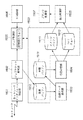
図1は、本発明の実施形態に係る印刷管理システム全体のシステム構成図である。 FIG. 1 is a system configuration diagram of the entire print management system according to the embodiment of the present invention.
図において、ネットワーク400には、多機能処理装置(MFP:Multi Function Peripheral)100、クライアントコンピュータ200、印刷管理サーバ300が接続されている。尚、図1では、各装置が1台ずつ接続されている例を示しているが、その接続台数は問わない。
In the figure, a
MFP100は、原稿を読取るスキャナ部、記録紙上に画像を形成するプリンタ部を搭載し、ネットワークプリンタ、コピー等の様々な機能を有する印刷装置として機能する。クライアントコンピュータ200は、オペレータの指示に従って各種アプリケーションプログラムを実行すると共に、オペレータからの印刷要求に応じて印刷データをネットワーク400に出力する。また印刷管理サーバ300で管理されているMFP100や印刷ジョブの監視や制御を補佐する処理も行なう。尚、MFP100により印刷する場合は、クライアントコンピュータ200で生成した印刷データを直接MFP100に転送する方法と、印刷管理サーバ300を介してMFP100に転送する方法とがある。
MFP 100 includes a scanner unit that reads a document and a printer unit that forms an image on recording paper, and functions as a printing apparatus having various functions such as a network printer and a copy. The
図2は、本実施形態に係るMFP100の構成を示す断面構造図である。
FIG. 2 is a cross-sectional structure diagram illustrating a configuration of the
MFP100は、原稿面に記録された画像を読取るスキャナ部110と、120,130,140,150の各ユニットで構成されるプリンタ部160、及び制御部170とを備える。
The MFP 100 includes a
制御部170は、このMFP100全体の制御を司るものであり、マイクロプロセッサを含むプリント基板として本装置に実装される。そして制御部170は、スキャナ部110の制御、ネットワーク通信やオペレータからの各種操作内容に応じた処理、及び以下に説明する印刷処理を行なう。
The
スキャナ部110は、原稿面を露光すると共に、走査移動する露光部111、及び原稿面からの反射光を結像し、電気信号に変換するラインCCD112を備える。制御部170は、このラインCCD112から逐次出力されてくる信号をA/D変換して画像データとして取込み、各種処理を行なうことになる。
The
また、プリンタ部160のレーザ露光部120は、制御部170により駆動される不図示のレーザ素子からのレーザ光を掃引するため、モータによって回転するポリゴンミラー121、及びそのレーザ光を感光ドラム135に向けて反射するミラー122を有する。作像部130は、感光ドラム135を回転駆動し、感光ドラム135の表面を帯電器によって帯電させる。感光ドラム135はレーザ露光部120によるレーザ光の掃引によってその表面に静電潜像を保持する。マゼンタ(M)、シアン(C)、イエロー(Y)、及びブラックの各色トナーを持つ現像ユニット131乃至134は、感光ドラム135の表面に形成された静電潜像にトナーを付着させてトナー像を形成する。こうして感光ドラム135上に形成されたトナー像は記録紙(シート)に転写される。このため、感光ドラム135と共に回転する転写ドラム136が設けられる。この転写ドラム136は、給紙/搬送部140から搬送されてきた記録紙を静電気の作用で巻き付ける。そして、転写ドラム136は、感光ドラム135上に生成された1つの色成分のトナー像を、自身に巻きつけた記録紙上に転写させる工程を4回行なうことで、記録紙上に4色の色成分を有するカラー像を形成する。
In addition, the
制御部170は、上記のようにして4色成分のトナー像の記録紙への転写を完了すると、その記録紙を転写ドラム136から剥離して定着部150に搬送する。定着部150は、ハロゲンヒータなどの熱源によって過熱された定着ローラ151を内蔵する。定着ローラ151は、作像部130から搬送されてきた記録紙上に転写されたトナーを、熱と圧力によって記録紙に溶解、定着させる。排紙ローラ152は、トナー定着済みの記録紙を外部(フィニッシャ装置)に排紙する。
When the transfer of the four color component toner images onto the recording paper is completed as described above, the
尚、本実施形態に係るMFP100は、両面印刷も可能である。排紙ローラ152の上流側(作像部130側)に記録紙センサ(不図示)が設けられている。従って、両面印刷の際は、このセンサが記録紙の後端を検出すると、制御部170がフラッパ153を所定角度回動させると共に、排紙ローラ152を逆回転させることで、記録紙を裏返し、給紙/搬送部140内の両面搬送径路142に向けて搬送する。給紙/搬送部140には、上記の両面搬送径路142よりの片面に印刷済みの記録紙を収納する両面記録用のシート収納庫143、更には、シートカセットやペーパーデッキに代表されるシート収納庫141を一つ以上有する。そして制御部170からの指示に応じてシート収納庫141に収納された複数のシートの中から一枚を分離し、作像部130、定着部150へ搬送する。
Note that the
次に、本実施形態に係るMFP100の制御部170の構成を説明する。
Next, the configuration of the
図3は、本実施形態に係るMFP100の制御部170の構成を示すブロック図である。
FIG. 3 is a block diagram illustrating a configuration of the
MFP100の制御部170は、マイクロプロセッサ等のCPU301、処理プログラムや各種データを格納してワークエリアを提供するRAM302、ブートプログラムや各種データを記憶するROM303を有するMFP制御部1000を備えている。このMFP制御部1000は、MFPの用途に応じて画像データを一時保存したり、以下に説明する各種処理部間のデータ経路を決定する等の交通整理の役割を担っている。尚、RAM302にロードされるプログラムはHDD1500にインストールされており、プログラム(機能)の実行が指示されると、そのプログラムがHDD1500からRAM302にロードされて実行される。
The
制御部170は、複数の印刷ジョブのデータを記憶可能な大容量の記憶装置であるハードディスク(以下、HDD)1500を備える。尚、大容量でランダムアクセス可能あれば、HDDに限らず、如何なる記憶装置でも構わない。MFP制御部1000は、このHDD1500をバッファとして利用する。そしてスキャナ部110から出力された画像データの複写処理、ネットワーク400上のクライアントコンピュータ200や印刷管理サーバ300から出力された印刷データに基づく印刷処理等の複数の機能を実現する。このMFP100には、フルカラー機器とモノクロ機器がある。これら機器では、色処理や内部データなどを除いて、基本的な構成要素は同じである。またフルカラー機器がモノクロ機器の構成を包含するので、ここではフルカラー機器を主に説明し、必要に応じて随時モノクロ機器の説明を加えることとする。
The
図3に示すように、MFP制御部1000には、複数の処理部が接続されている。入力画像処理部1001は、紙原稿などの画像を読み取り、その読み取った画像データを画像処理する。ネットワークインタフェース部1003は、ネットワーク400を利用して印刷データや装置情報の送受信を行なう。文書管理部1006は、MFP制御部1000の制御下で、入力画像処理部1001からの画像データや、ネットワークインタフェース部1003を介して受信した印刷データを解析することで得られる画像データをHDD1500へ格納する処理を行なう。また、この文書管理部1006は、MFP制御部1000の制御下で、HDD1500に格納された画像データを適宜読み出す処理も行なう。MFP制御部1000は、オペレータによる操作部1008からの指示に従って、HDD1500から読み出した画像データの出力先を決定する。例えば、MFP制御部1000が出力先としてプリンタ処理部1007を設定した場合は印刷処理を行なう。文書管理部1006は、画像データをHDD1500に記憶する際に必要に応じて画像データを圧縮して格納したり、逆に圧縮して格納された画像データをHDD1500から読み出す際に元の画像データに伸長(復号)する。このため制御部170は、圧縮伸長部1009を備える。またMFP制御部1000は、ネットワークインタフェース部1003を介して受信した印刷データがJPEG,JBIG,ZIP等の圧縮データである場合、圧縮伸長部1009で解凍(伸長)するように制御する。リソース管理部1010は、MFP制御部1000の制御下で、フォント、カラープロファイル、ガンマテーブル等に共通に扱われる各種パラメータテーブル等を読み出し可能に保持管理する。またMFP制御部1000からの要求に応じて、新しいパラメータテーブルを格納したり、修正して更新したりする。
As shown in FIG. 3, a plurality of processing units are connected to the
次に、MFP制御部1000がネットワークインタフェース部1003を介して印刷データを受信した場合の処理を説明する。
Next, processing when the
MFP制御部1000が印刷データを受信した場合、RIP(Raster Image Processor)部1011でラスタ画像処理を施す。またMFP制御部1000は、印刷する画像に対して、必要に応じて出力画像処理部1012で印刷のための画像処理を行う。更に、その際に作られる画像データの中間データやプリントレディデータ(プリントのためのビットマップデータやそれを圧縮したデータ)を、必要に応じて文書管理部1006を介してHDD1500に格納する。このHDD1500への格納処理は、プリンタ処理部1007の動作とは非同期である。
When the
またMFP制御部1000は、プリンタ処理部1007の印刷処理タイミングに併せて、HDD1500に格納された各ページの画像データを、文書管理部1006を介して読み出し、プリンタ処理部1007に出力する処理を行なう。このとき、その印刷データの記述に従って後処理部1013を制御する。この後処理部1013は、シートの仕分け処理やシートの仕上げ処理を行うフィニッシャ装置を制御する。
In addition, the
更に、操作部1008は、様々な機能を選択したり、操作指示したりするユーザインタフェースとして機能する。またオペレータに対して様々な表示メニューを提供したり、文書管理部1006で管理されている画像データをプレビュー表示したりするため、高解像度の表示装置と、各種指示ボタンやタッチパネルを備える。オペレータはコピーする際にも、この操作部1008を操作してコピー指示を行うことになる。
Further, the
次に、本実施形態に係るMFP制御部1000の処理概要の一例を説明する。この処理は、MFP制御部1000のCPU301、及びファームウェアを格納しているRAM302,ROM303と、図3で示した各種処理部によって実現する。
Next, an example of a processing outline of the
図4は、本実施形態に係るMFP制御部1000の処理概要の一例を説明する図である。
FIG. 4 is a diagram for explaining an example of a processing outline of the
ネットワークインタフェース制御部1601は、図3のネットワークインタフェース部1003の制御を司っている。そして通信プロトコルの解析を行い、クライアントコンピュータ200或いは印刷管理サーバ300からの印刷データの受信、及び受信した印刷データをジョブチケット解析部1602に転送する処理を行なう。ジョブチケット解析部1602は、ジョブチケットを解析して印刷ジョブの属性をジョブ制御部1600に伝達し、印刷ジョブを不図示の管理テーブルに登録し、印刷データを受信バッファ1610に格納する。印刷データ解析部1603は、受信バッファ1610に印刷データが格納されたことを検知すると、その印刷データの解析処理を開始する。即ち、印刷データ解析部1603は、受信バッファ1610に格納されている印刷データを読み込み、その印刷データを解析して各コマンドに対応するオブジェクト(中間コード)を生成し中間バッファ1611に格納する。本実施形態では、プリンタ部160がサポートしているコマンドはPDL(ページ記述言語)とするが、PDLデータだけでなく、ページ毎に印刷を行うことが可能なデータであれば、その種類は問わない。
The network
描画処理部1604は、中間バッファ1611にデータが格納されたことを検知すると描画処理を開始する。即ち、描画処理部1604は中間バッファ1611から中間データをページ毎に読み出し、通常の印刷の場合においては(Holdキュー1612への格納が指示されていない場合)、1ページ分の画像データを生成してイメージバッファ1613に格納する。
When the
出力制御部1605は、イメージバッファ1613に1ページ分の画像データが格納されていることを検知すると、それを読み出してプリンタ処理部1007の制御を司るプリンタ制御部1607に出力する処理を行なう。また描画処理部1604は、Holdキュー1612への格納を指定した印刷ジョブの場合、描画した各ページの画像データをHoldキュー1612に順次格納する。この場合、出力制御部1605は直ぐに起動せず、UI制御部1606からHoldキュー1612からの印刷指示があった場合に、そのジョブの印刷を行う。ここでHoldとは、そのデータを直ぐに印刷せず、一旦、HDD等の記憶装置内に印刷ジョブとして格納し、オペレータから操作部1008を介して印刷指示があって初めて印刷を開始する機能のことである。Holdは、Holdキュー1612に格納された印刷ジョブの試しプリントを行い、印刷結果に問題がなければ、本印刷(複数部数)を行う場合等に使用される。この結果、本印刷の際には、その印刷データをクライアントコンピュータ200や印刷管理サーバ300からMFP100に送信し直す必要がなくなる。
When the
UI制御部1606は、ユーザインタフェースを制御する部分であり、操作部1008への表示データの転送と、操作部1008からの入力をMFP制御部1000に通知する処理を行なう。操作部1008に設けられる表示部は、本実施形態では、液晶ディスプレイである。また操作部1008には幾つかのキーが配置されていると共に、液晶ディスプレイの前面にはタッチパネルが設けられている。UI制御部1606は、ユーザの操作に応じた文字列の表示、画面の切替え、設定値を他のモジュールに伝達するなどの制御を行う。ジョブ制御部1600は、MFP100内のジョブを管理する部分であり、ジョブの生成と消滅、ジョブの状態、ジョブの処理順序などを制御する。特にジョブ制御部1600は、イメージバッファ1613、Holdキュー1612のいずれかの画像データを出力制御部1605に出力するかを決定するため、内部に印刷実行キューを備えている。この印刷実行キューは、HDD1500に格納されてもよいが、情報量が少ないのでMFP制御部1000のRAM302に記憶されるものとする。この印刷実行キューには、通常の印刷ジョブの場合は、そのジョブを特定する情報(後述するジョブID)が自動的に設定される。またHoldキュー1612に格納された印刷ジョブの場合は、オペレータが印刷を実行して初めて、そのジョブIDが印刷実行キューに登録される。従って、ジョブ制御部1600は、この印刷実行キューに登録されたジョブIDに基づいて、該当する画像データを格納しているのが、イメージバッファ1613かHoldキュー1612かを判断する。そして、その格納しているバッファが判明すると、該当する印刷ジョブを構成する各ページの画像データを、出力制御部1605に出力するように制御する。
The
次に、MFP制御部1000の処理プログラムの1つである、ジョブ制御部1600の処理を説明する。
Next, processing of the
図5は、本実施形態に係るMFP制御部1000の処理プログラムの1つである、ジョブ制御部1600の処理を説明するフローチャートである。このフローチャートで示す処理は、MFP制御部1000のRAM302に記憶されたプログラムに従ってCPU301の制御の下に実行される。
FIG. 5 is a flowchart for explaining processing of the
まずステップS101で、MFP制御部1000は、印刷実行キューを読み込む。次にステップS102に進み、未印刷ジョブが存在するか否かを判断する。もし未印刷ジョブがないと判断した場合はステップS101の処理に戻る。一方、ステップS102で、MFP制御部1000が印刷実行キューに未印刷ジョブがあると判断した場合はステップS103に進む。このステップS103では、MFP制御部1000は、その未印刷ジョブのジョブID(後述)から、該当する画像データがイメージバッファ1613、Holdキュー1612のいずれにあるかを探し出し、1ページ分の画像データを読み込み、印刷処理を行なう。そして次にステップS104で、全ページの印刷が完了したと判断するまでこの処理を繰り返す。このステップS104で、MFP制御部1000が、全ページの印刷処理が完了したと判断した場合はステップS105に進む。ステップS105では、MFP制御部1000が、その印刷が完了した印刷ジョブのIDを印刷実行キューから削除すると共に、その処理が完了した印刷ジョブをHDD1500から削除する。尚、後述するように、試しプリントの場合には、MFP制御部1000は、印刷実行キューからジョブIDを削除するものの、実体の印刷ジョブは削除しない。
First, in step S101, the
一方、クライアントコンピュータ200には、各種アプリケーション、並びに本実施形態に係るMFP100を使用するためのプリンタドライバがインストールされている。
On the other hand, the
図6は、本実施形態に係るクライアントコンピュータ200のプリンタドライバによる印刷設定画面の一例を示す図である。プリンタドライバは、実行中のアプリケーションの印刷メニューをユーザが選択した場合に、この画面を表示する。
FIG. 6 is a diagram showing an example of a print setting screen by the printer driver of the
この設定画面中の「プリンタ名」601は、プルダウンリストボックス形式になっている。ここでユーザが、使用するMFPを選択すると602で示すように、その下の「状態」にMFPの状態、「種類」にプリンタドライバの種類、「場所」にMFPの設置場所の情報、「コメント」にMFPの管理者からのコメント情報が表示される。これらの情報は、この印刷設定画面を表示した際、或いは使用するMFPを選択した際、該当するMFPに対して情報転送要求メッセージを発行することで得られる。尚、印刷データをMFPにより印刷させずにファイルに出力したい場合は、「ファイルへ出力」のチェックボックス603を判断する。こうすることにより、プリンタドライバで生成された印刷データを、クライアントコンピュータ200が有する記憶装置にファイルとして格納することができる。
“Printer name” 601 in this setting screen is in a pull-down list box format. When the user selects an MFP to be used, as shown at 602, the “status” below the MFP status, the “type” the printer driver type, the “location” information on the MFP installation location, “comment” "Displays comment information from the administrator of the MFP. Such information can be obtained by issuing an information transfer request message to the corresponding MFP when the print setting screen is displayed or when an MFP to be used is selected. If print data is to be output to a file without being printed by the MFP, a
「印刷範囲」604には、印刷すべきページを選択する項目として、「すべて」、「現在のページ」、「選択した部分」、「ページ指定」のラジオボタンが設けられている。ユーザはこれらのうちの1つを選択することになる(デフォルトは「すべて」とする)。ユーザがポインティングデバイスを用いて「ページ指定」を選択した場合は、エディットボックスが入力可能な状態に遷移するので、ユーザはキーボードを用いて印刷したいページ番号を入力することになる。 In the “print range” 604, radio buttons of “all”, “current page”, “selected portion”, and “page designation” are provided as items for selecting pages to be printed. The user will select one of these (the default is “all”). When the user selects “specify page” using the pointing device, the edit box enters a state where input is possible, and the user inputs the page number to be printed using the keyboard.
更に「印刷対象」のプルダウンリストボックス605により、印刷対象となる文書の属性を選択が可能である。「印刷指定」のプルダウンリストボックス606により、全てのページを印刷するのか、奇数或いは偶数ページだけを印刷するのかを指定可能である。
Further, an attribute of a document to be printed can be selected from a “print target” pull-
「印刷部数」607では、印刷する部数を設定可能である。ユーザは「部数」のスピンボックスに印刷したい部数を入力する。また、複数部数をページ単位ではなく部単位で印刷する場合は、「部単位で印刷」のチェックボックス608を選択状態にする。
In “number of copies” 607, the number of copies to be printed can be set. The user inputs the number of copies to be printed in the “number of copies” spin box. When printing a plurality of copies in units of copies instead of in units of pages, the “print in units of copies”
「拡大/縮小」609では、「1枚あたりのページ数」のプルダウンリストボックス610により、N−up印刷(1つの印刷面に複数ページをレイアウトする印刷)を指定できる。「用紙サイズの指定」のプルダウンリストボックス611は、原稿サイズに対する記録紙の用紙サイズを選択するためのものである。また「プロパティ」ボタン612は、更なる詳細な印刷属性を設定するためのものである。
In “enlargement / reduction” 609, N-up printing (printing a plurality of pages on one printing surface) can be designated by a pull-
ユーザがプリンタドライバの設定画面の設定を終了したならば、「OK」ボタン613を指示することにより、印刷データをMFP100に転送して印刷させたり、ファイルに出力したりすることができる。また印刷やファイル出力を止める場合は、「キャンセル」ボタン614を指示すればよい。
When the user finishes setting the printer driver setting screen, by instructing an “OK”
図7は、図6の画面上の「プロパティ」ボタン612をユーザがポインティングデバイスで指示した場合に表示される設定画面の一例を示す図である。尚、この設定画面は、複数のタブを備え、初期状態では「ページ設定」タブが選択された状態を示している。
FIG. 7 is a diagram showing an example of a setting screen displayed when the user designates the “property”
「お気に入り」のプルダウンリストボックス701は、予め決められたページ設定モードの中から最適なページ設定を選択するためのものである。また、プリンタドライバが、「設定確認」ボタン702が指示されたことを検出した場合には、プロパティ設定画面で設定した内容に従って、その上に表示されているページイメージ領域内に、先頭ページの印刷イメージを表示する。
A “favorite” pull-
「出力方法」のプルダウンリストボックス703では、MFP100により通常の印刷をさせるか、MFP100のHoldキュー1612に格納するのかといったような出力方法を指定する。図では、Holdキュー1612への格納を示す「Hold」がカーソルにより指示されている。このようにHoldキュー1612への格納を指定した場合、プリンタドライバは、Holdキュー1612である旨のジョブチケットを有する印刷データを生成して出力する。これを受信したMFP制御部1000は、画像データを生成する処理を経た後、各ページをHoldキュー1612に格納するまでの処理を行なう。つまり印刷処理は行なわない。印刷処理を開始するのは、MFP制御部1000が操作部1008から印刷指示入力があったと判断した場合である。
In the “output method” pull-
「原稿サイズ」と「出力用紙サイズ」のプルダウンリストボックス704,705は、印刷対象となる原稿サイズと記録紙の用紙サイズを選択するためのものである。「部数」のスピンボックス706は、印刷したい部数を入力するためのものであり、「印刷の向き」のラジオボタンは、「縦」、「横」といったような記録紙の向きを選択するものである。「ページレイアウト」のプルダウンリストボックス707は、N−up印刷(1つの印刷面に複数ページをレイアウトする印刷)を指定するためのものである。「倍率を指定する」のチェックボックス708をチェックした場合は、「倍率」のスピンボックス709に拡大/縮小の倍率を%単位で入力可能である。「スタンプ」のチェックボックス710をチェックした場合は、プルダウンリストボックス711で予め決められたスタンプの種類を選択可能になる。「スタンプ編集」ボタン712が指示された場合は、スタンプの種類を追加したり編集したりすることが可能になる。「ユーザ定義用紙」ボタン713は、ユーザが記録紙を定義することを可能にするものである。「ページオプション」ボタン714は、ユーザが更に詳細なページオプションを設定することを可能にする。また「標準に戻す」ボタン715は、各種設定内容をデフォルトの設定内容に戻すものである。
The “original size” and “output paper size” pull-
こうしてユーザがプリンタドライバのプロパティ設定画面の設定を終了したならば、「OK」ボタン716を指示すれば良い。この「OK」ボタン716が指示されたことを検出すると、プリンタドライバが、これらの印刷属性を実際の印刷に反映する。プロパティ設定画面の設定を止める場合は、「キャンセル」ボタン717を押下すればよい。「ヘルプ」ボタン718は、プロパティ設定画面のヘルプ画面を表示するものである。
When the user finishes setting the printer driver property setting screen in this way, an “OK”
ここでクライアントコンピュータ200のCPU(不図示)が、ユーザにより図6の「OK」ボタン613が指示されたことを検出する。これによりプリンタドライバのプログラムに従って、アプリケーションより渡されるデータを受信し、ジョブチケット、並びにPDLデータで構成される印刷データの生成処理を行なう。その後、クライアントコンピュータ200のOSは、本実施形態に係るMFP100にその印刷データを印刷ジョブとして転送することになる。
Here, the CPU (not shown) of the
図8は、本実施形態に係るMFP100に転送される印刷データの構造を説明する図である。尚、ここで印刷データは、属性情報(ジョブチケット)とPDLデータとを有している。
FIG. 8 is a diagram illustrating the structure of print data transferred to the
図8の例では、属性情報(全体設定)には「ジョブ名」、「部数」、「出力用紙サイズ」、「用紙タイプ」、「印刷方法」、「用紙の向き」、「カラーモード」、「出力方法」等の属性のIDと、その設定値が格納されている。また属性情報はXML等の形式で記述されているものとする。各属性には図6に示したプリンタドライバの設定画面、図7に示したプロパティ設定画面による設定に従った設定値が設定される。また、出力方法は、図7に示すように「Hold」が指示されているものとする。 In the example of FIG. 8, the attribute information (whole setting) includes “job name”, “number of copies”, “output paper size”, “paper type”, “printing method”, “paper orientation”, “color mode”, The ID of an attribute such as “output method” and the set value thereof are stored. The attribute information is described in a format such as XML. Each attribute is set with a setting value according to the setting on the printer driver setting screen shown in FIG. 6 and the property setting screen shown in FIG. Further, it is assumed that “Hold” is designated as the output method as shown in FIG.
次に、本実施形態に係るMFP100が有する操作部1008での表示例について説明する。
Next, a display example on the
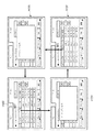
図9は、本実施形態に係るMFP100の操作部1008の表示部に表示される画面の一例を示す図である。尚、本実施形態に係るMFP100の操作部1008の表示部にはタッチパネルが用いられている。また、機能に応じてタブが分かれており、本実施形態では「コピー」、「ホールド」の各タブが存在する。
FIG. 9 is a diagram showing an example of a screen displayed on the display unit of the
900では、この内の「ホールド」タブがアクティブになっている状態を示している。この表示画面をホールドタブのメイン画面(ホールドジョブリスト画面)という。このホールドジョブリスト画面には、HDD1500内のHoldキュー1612に格納された各印刷ジョブのジョブ情報がリスト形式で表示されている。Holdキュー1612はMFP100に1つしか存在せず、印刷ジョブを一時溜め置いておく用途で使用される。また図9には、Holdキュー1612に格納されている印刷ジョブのジョブ情報として、ジョブ名、ユーザ名、日付/時刻(印刷ジョブが格納された日付と時刻)が表示されている。また、このHoldキュー1612に格納されている各印刷ジョブのジョブ情報が日付/時刻の昇順(日付け、時刻の古い順)で表示されている。
At 900, the “Hold” tab is active. This display screen is called a main screen (hold job list screen) of the hold tab. On the hold job list screen, job information of each print job stored in the
このホールドジョブリスト画面では、オペレータは、ジョブリストの項目にある「ジョブ名」ボタン901或いは「日付/時刻」ボタン902をタッチする。これにより、Holdキュー1612に格納されている各印刷ジョブのジョブ情報を、名前順、或いは日付/時刻に並べ替えて表示することができる。MFP制御部1000は、「ジョブ名」或いは「日付/時刻」ボタン901,902がタッチされたことを検出すると、Holdキュー1612に格納されている各印刷ジョブのジョブ情報を並べ替える。即ち、その指示された「ジョブ名」或いは「日付/時刻」の順に並べ替える。そして、その結果を操作部1008の表示画面に反映させる処理を行う。そして図9の画面上で各ジョブが表示されている行をタッチすることによって、処理対象の印刷ジョブを選択できる。また印刷ジョブを複数選択することが可能であり、複数の印刷ジョブを選択した場合は、印刷ジョブの左の番号で選択した順序が認識できる。複数の印刷ジョブを選択してプリント指示を行う場合には、印刷させようとするジョブを選択状態にした後、「プリント」ボタン903をタッチする。この結果、選択した順序に従って印刷処理が開始される。
On this hold job list screen, the operator touches a “job name”
またオペレータは、印刷ジョブを選択して画面下のボタンをタッチすることで、該当するジョブの操作が行える。この操作を指示するボタンには、「プレビュー」、「試しプリント」、「プリント」、「消去」、「編集」ボタンが存在する。「プレビュー」は、選択された印刷ジョブのプレビュー表示を行う。「試しプリント」は、選択された印刷ジョブの試しプリント設定を表示する。「プリント」は、選択された印刷ジョブの本印刷を行う。「消去」は選択された印刷ジョブをホールドジョブリスト画面から消去する(印刷ジョブの実体は残す)。「編集」は、選択された印刷ジョブの印刷設定を変更することができる。 The operator can select the print job and touch the button at the bottom of the screen to operate the corresponding job. Buttons for instructing this operation include “Preview”, “Trial Print”, “Print”, “Erase”, and “Edit” buttons. “Preview” displays a preview of the selected print job. “Test print” displays the test print setting of the selected print job. “Print” performs actual printing of the selected print job. “Delete” deletes the selected print job from the hold job list screen (the print job entity remains). “Edit” can change the print setting of the selected print job.
尚、MFP100を使用する際にユーザ名とパスワードを設定することが可能となっている。910は、MFP100にユーザ名とパスワードが設定されている場合に、MFP100の起動時に表示されるログイン画面の一例を示している。このログイン画面910で、ユーザ名と正しいパスワードが入力されると、「コピータブ」のメイン画面、或いは「ホールドタブ」のメイン画面に遷移する。尚、ここでも操作部1008の表示画面にタッチ式のキーボードを表示して、それを使用してユーザ名とパスワードを入力するものとする。
A user name and password can be set when using the
また、MFP100にユーザ名とパスワードが設定されている場合は、「ログアウト」ボタン904が表示される。MFP制御部1000は、この「ログアウト」ボタン904がタッチされたことを検出すると、910で示すログイン画面を表示する。ここでユーザ名と、対応するパスワードが入力されると認証に成功し、その画面は900で示すホールドジョブリスト画面に戻って、ユーザによる操作が可能となる。
In addition, when a user name and password are set in the
図10は、本実施形態に係るMFP100の操作部1008の表示部で、オペレータが「日付/時刻」ボタン902を繰り返しタッチした場合(項目の指示操作)に表示されるホールドタブの画面遷移の一例を示す図である。
FIG. 10 shows an example of screen transition of the hold tab displayed when the operator repeatedly touches the “Date / Time” button 902 (item instruction operation) on the display unit of the
図10において、10000は、図9の900で示すホールドジョブリスト画面に対応し、Holdキュー1612に格納されている各印刷ジョブのジョブ情報が日付/時刻の昇順で表示されている。ここでMFP制御部1000が、「日付/時刻」ボタン902がタッチされたことを検出すると、10001で示すように、ポップアップダイアログを表示して、各印刷ジョブのジョブ情報のソート中である旨を表示する。そして各印刷ジョブのジョブ情報の並べ替え処理が完了するのを待つ。こうして並べ替え処理が完了すると、MFP制御部1000は、10002で示すように、ホールドジョブリスト画面を表示する。ここでは、Holdキュー1612に格納されている各印刷ジョブのジョブ情報が日付/時刻の降順(最新のものから古い順に)で表示されている。更にこの状態で、MFP制御部1000が、「日付/時刻」ボタン902がタッチされたことを検出すると、10003で示すように、ソート中であることを示すポップアップダイアログを表示し、各印刷ジョブのジョブ情報の並べ替え処理が完了するのを待つ。並べ替え処理が完了した場合、MFP制御部1000は、10000で示すホールドジョブリスト画面を表示する。10000では、Holdキュー1612に格納されている各印刷ジョブのジョブ情報が日付/時刻の昇順(古いものから新しい順に)で表示されている。
In FIG. 10, 10000 corresponds to the hold job list screen indicated by 900 in FIG. 9, and the job information of each print job stored in the
図11は、本実施形態に係るMFP100の操作部1008の表示部で、オペレータが「ジョブ名」ボタン901を繰り返しタッチした場合に表示されるホールドタブの画面遷移の一例を示す図である。
FIG. 11 is a view showing an example of screen transition of the hold tab displayed when the operator repeatedly touches the “job name”
1100は、Holdキュー1612に格納されている各印刷ジョブのジョブ情報がジョブ名の昇順で表示されている場合を示す。ここではジョブ名の順(昇順)に印刷ジョブがリスト表示されている。この状態で、MFP制御部1000が、「ジョブ名」ボタン901がタッチされたことを検出すると、1101で示すようにソート中であることを示すポップアップダイアログを表示し、各印刷ジョブのジョブ情報の並べ替え処理が完了するのを待つ。並べ替え処理が完了すると、MFP制御部1000は、1102で示すように、ホールドジョブリスト画面を表示する。この1102では、Holdキュー1612に格納されている各印刷ジョブのジョブ情報が、ジョブ名の降順で表示されている。更に、1102で、MFP制御部1000が、「ジョブ名」ボタン901がタッチされたことを検出すると、1103で示すようにソート中であることを示すポップアップダイアログを表示し、各印刷ジョブのジョブ情報の並べ替え処理が完了するのを待つ。こうして並べ替え処理が完了すると、MFP制御部1000は、1100で示すような、ジョブ情報がジョブ名の昇順で表示されているホールドジョブリスト画面を表示する。
尚、この実施形態では、「ジョブ名」ボタン901或いは「日付/時刻」ボタン902による配列変更指示に応じて、その配列順を昇順と降順とで交互に切り替えているが、本発明はこれに限定されず、常に昇順或いは降順で表示しても良い。
In this embodiment, the arrangement order is alternately switched between ascending order and descending order in accordance with an instruction to change the arrangement by the “job name”
図12は、本実施形態に係るMFP100の操作部1008の表示部に表示される画面の一例を示す図である。ここではオペレータがホールドタブをタッチした場合に表示されるホールドジョブリスト画面の一例を示している。ここでは前述の図11の1100で示すように、ジョブ情報がジョブ名の昇順で表示されているホールドジョブリスト画面が表示されている。
FIG. 12 is a diagram showing an example of a screen displayed on the display unit of the
1200では、Holdキュー1612に格納されている各印刷ジョブのジョブ情報がジョブ名の昇順で表示され、ジョブ名「ドキュメント3」のジョブが選択された状態にある。この状態で、MFP制御部1000が、「試しプリント」ボタン1201がタッチされたことを検出すると、1202で示す画面を表示する。この画面では、「ドキュメント3」の印刷ジョブに対する試しプリントが設定された場合の表示例を示している。尚、この1202で示す画面には、「全ページ」、「指定ページ」、「開始ページ」、「終了ページ」、「キャンセル」、「プリント開始」ボタンが設けられている。
In 1200, the job information of each print job stored in the
オペレータが印刷ジョブの全ページを試しプリントする場合は「全ページ」ボタンをタッチする必要がある。一方、オペレータが印刷ジョブの一部のページだけを試しプリントする場合は、「指定ページ」ボタンをタッチする必要がある。「指定ページ」ボタンがタッチされた場合、オペレータが「開始ページ」ボタンをタッチすると、試しプリントの開始ページを操作部1008に設けられた数字キーで入力可能となる。また、オペレータが「終了ページ」ボタンをタッチすると、試しプリントの終了ページを操作部1008に設けられた数字キーで入力可能となる。図12の例では、開始ページが5ページで、終了ページが10ページである、5〜10ページの試し印刷が指示されている。
When the operator prints out all pages of the print job, it is necessary to touch the “all pages” button. On the other hand, when the operator trial prints only a part of the pages of the print job, it is necessary to touch the “specified page” button. When the “designated page” button is touched, when the operator touches the “start page” button, the test print start page can be input using the numeric keys provided on the
この状態で、オペレータが「プリント開始」ボタン1203をタッチすると、この印刷ジョブの試しプリント処理を開始する。換言すれば、MFP制御部1000は、「プリント開始」ボタン1203がタッチされたことを検出すると、その印刷ジョブを印刷実行キューへ登録する処理を行なう。またオペレータが「キャンセル」ボタン1204をタッチすると、1200で示す画面に戻る。このとき、1200で示すホールドジョブリスト画面では、試しプリント設定画面に遷移する前の表示形式、即ち、ジョブ名を昇順で表示する表示形式が保持された状態で、Holdキュー1612に格納されている印刷ジョブのジョブ情報が再表示される。
In this state, when the operator touches a “print start”
図13は、本実施形態に係るMFP100のジョブを管理するための各種テーブルを説明する図である。これらテーブルは、HDD1500に保持されている。
FIG. 13 is a diagram for explaining various tables for managing jobs of the
ジョブ管理テーブル1300は、ジョブID、属性情報管理テーブル1301へのポインタ、画像データ1302へのポインタを有している。尚、ジョブIDは、そのジョブを管理するため、MFP制御部1000が発行するものである。このジョブ管理テーブル1300には、アクティブジョブ用、ホールドジョブ用、ホールドジョブリスト表示用の各テーブル1300a,1300b,1300cが存在する。MFP制御部1000は、図9の900の「ジョブ名」或いは「日付/時刻」ボタン901,902がタッチされたことを検出すると、ホールドジョブリスト画面の表示形式を決定する。そしてホールドジョブのジョブ管理テーブル1300bを基に、ホールドジョブリスト表示用のジョブ管理テーブル1300cを再構築する。ここでは例えば、図12の1200で示すような表示順に対応して、ホールドジョブリスト表示用のジョブ管理テーブル1300cのジョブIDの配列順を変更する。従って、このホールドジョブリスト表示用のジョブ管理テーブル1300cの配列順に印刷ジョブを表示することにより、ユーザの最新の操作により変更された表示順で、ホールドされている印刷ジョブのリスト(一覧)を表示することができる。属性情報管理テーブル1301には、印刷ジョブの各属性が記憶されており、各印刷ジョブに対応する属性IDと、その属性IDに対応する設定値が登録されている。更に、画像データ1302は、各印刷ジョブ毎にページ単位で管理されている。
The job management table 1300 has a job ID, a pointer to the attribute information management table 1301, and a pointer to the
図14は、本実施形態に係るMFP100のユーザ情報を管理するためのユーザ情報管理テーブルを説明する図である。このユーザ情報管理テーブル(配列保持部)も、HDD1500に保持されている。
FIG. 14 is a diagram illustrating a user information management table for managing user information of the
このユーザ情報管理テーブルは、ユーザID、ユーザ名、パスワード、ジョブリストの表示形式を含んでいる。デフォルトでは、ユーザ名とパスワードの全ての領域に「null」が格納されており、ジョブリストの表示形式の領域には、「日付/時刻の昇順」、「日付/時刻の降順」、「ジョブ名の昇順」、或いは「ジョブ名の降順」のいずれかが格納されている。MFP制御部1000は、ユーザ名とパスワードの全ての領域に「null」が格納されている場合、MFP100にユーザ名とパスワードが設定されていないと判断する。一方、「null」以外のデータが格納されている場合は、ユーザ名とパスワードが設定されていると判断する。
The user information management table includes a user ID, a user name, a password, and a job list display format. By default, “null” is stored in all areas of the user name and password, and the display area of the job list includes “date / time ascending order”, “date / time descending order”, and “job name”. "Ascending order" or "Job name descending order" is stored. If “null” is stored in all areas of the user name and password, the
MFP制御部1000は、図9の910で示すログイン画面で、ユーザ名と正しいパスワードが入力されたと判断すると、そのユーザIDに関連付けられたジョブリストの表示形式をHDD1500から読み出す。そして図13に示すホールドジョブのジョブ管理テーブル1300bを基に、ホールドジョブリスト表示用のジョブ管理テーブル1300cを再構築する。
When the
次に、本実施形態に係るMFP制御部1000の処理手順を図15及び図16のフローチャートに従って説明する。
Next, the processing procedure of the
図15は、本発明の実施形態に係るMFP制御部1000による処理を説明するフローチャートである。この処理を実行するプログラムは、実行時にはRAM302に記憶されており、CPU301の制御の下に実行される。
FIG. 15 is a flowchart for explaining processing by the
MFP100に電源が投入されると、MFP制御部1000は、ステップS201で印刷データの受信を待つ。MFP制御部1000が、印刷データの受信を検出するとステップS202の処理に進み、その印刷データの入力処理を行なう。これらステップS201、S202の処理は、MFP制御部1000が実行するネットワークインタフェース制御部1601の処理でもある。
When the
次に、MFP制御部1000は、処理をステップS203に進め、ジョブチケット解析部1602の処理を実行して、入力した印刷データを解析する。MFP制御部1000は、解析の結果、印刷データ(PDLデータ)については、HDD1500の受信バッファ1610に格納する。またMFP制御部1000は、ジョブチケットを解析し、そのジョブがHoldキュー1612への格納か、通常印刷のいずれであるかを判定する。MFP制御部1000は、ジョブがHoldキュー1612への格納であれば、ホールドジョブのジョブ管理テーブル1300bに登録する処理を行う。一方、通常印刷の場合には、そのまま印刷実行キューに登録することになるので、MFP制御部1000は、アクティブジョブのジョブ管理テーブル1300aに登録する処理を行う。
Next, the
MFP制御部1000は、次にステップS204に処理を進め、受信バッファ1610に記憶されているPDLデータを解析する(PDLデータ解析処理の詳細は後述する)。次にステップS205に進み、MFP制御部1000は、コマンドがページクローズ命令であるか否か(1ページ分の終了を示す命令であるかのチェックも含む)を判定する。MFP制御部1000は、コマンドがページクローズ命令であると判断した場合はステップS206に処理を進め、ここまで生成した中間コードを1ページ分のデータとして認識する処理を行う。中間コードは前述のようにページ毎に管理される。
Next, the
またMFP制御部1000が、ステップS205において、コマンドがページクローズ命令以外であると判断した場合はステップS207に処理を進め、各コマンドに応じて内部処理に適した形式の中間コードを生成する。
If the
こうしてステップS206或いはステップS207を実行した後、MFP制御部1000はステップS208に処理を進め、解析すべきデータが受信バッファ1610に存在するか否かを判定する。ここでMFP制御部1000が解析すべきデータが存在すると判断した場合はステップS204へ戻り、PDLデータの解析処理を繰り返す。またMFP制御部1000が解析すべきデータが受信バッファ1610に無いと判断した場合は、処理をステップS209に進める。ステップS209では、MFP制御部1000は、1ページ分以上の中間コードが存在するか否かを判定する。ここで1ページ分以上の中間コードが存在しないと判断するとステップS201の受信処理に進む。MFP制御部1000が1ページ分以上の中間コードが存在すると判断した場合はステップS210に進み、1ページ分の中間コードを中間バッファ1611から読み出し、その中間コードから画像データを生成する処理を行なう。次にステップS211に進み、MFP制御部1000は、印刷ジョブがHoldキュー1612への格納が指定されたジョブであるか否かを判定する。Holdキュー1612への格納が指定されているジョブである場合は、MFP制御部1000はステップS212に処理を進め、生成した画像データをHDD1500に確保されたHoldキュー1612に格納する。
After executing step S206 or step S207 in this manner, the
一方、MFP制御部1000は、ジョブがHoldキュー1612への格納が指定されていないと判断した場合は、ステップS213に処理を進める。ステップS213では、MFP制御部1000は、1ページ分の画像データをイメージバッファ1613に格納する。次にステップS214に進み、MFP制御部1000は、そのイメージバッファ1613に格納したページが、通常印刷ジョブの先頭ページであれば、そのジョブIDを印刷実行キューに登録する。このとき、他のジョブの印刷処理を行なっていない場合、即ち、印刷実行キューの先頭に登録された場合には、イメージバッファ1613より1ページ分の画像データを読み出す。そしてそれをビデオ信号に変換し、プリンタ制御部1607に転送する処理を開始させる。これによりプリンタ制御部1607は、そのビデオ信号を基づいて実際に記録紙への印刷を行ない、印刷済みの記録紙を外部に排紙する処理を行なうことになる。
On the other hand, if the
尚、プリンタ制御部1607へのビデオ信号の転送と、イメージバッファ1613への格納処理は同期しない。通常は、プリンタ部160の印刷速度より、画像データへの変換が早いので、イメージバッファ1613には未印刷のページの画像データが徐々に増えていくことになる。
Note that the transfer of the video signal to the
こうしてステップS214の処理の後、MFP制御部1000はステップS209へ戻る。ステップS209で1ページ分の中間コードが完成していない場合は、更にステップS201に戻り、続きの入力データを待つ。
Thus, after the process of step S214, the
図16は、本実施形態に係るMFP制御部1000によるホールドジョブリストの表示処理と、オペレータによるタッチパネルへの入力に応じた処理を示すフローチャートである。MFP制御部1000は、図16のフローチャートで示す処理を、図15のメイン処理とは別タスクとして実行する。この処理を実行するプログラムは、実行時にはRAM302に記憶されており、CPU301の制御の下に実行される。
FIG. 16 is a flowchart showing a hold job list display process by the
まずステップS301で、MFP制御部1000は、HDD1500から図14に示すユーザ情報管理テーブルを読み出し、MFP100にユーザ名とパスワードが設定されているか否かを判定する。ここでMFP100に対してユーザ名とパスワードが設定されていないと判断した場合には、ユーザ名、パスワードの入力を省略してステップS304に処理を進める。
First, in step S <b> 301, the
一方、MFP制御部1000が、MFP100に対してユーザ名とパスワードが設定されていると判断した場合は、処理をステップS302に進め、図9の910で示すようなログイン画面を表示する。次にステップS303に進み、MFP制御部1000は、オペレータにより入力されたユーザ名とパスワードが正しいか否かを判定し、正しいと判定しするとステップS304に処理を進めるが、そうでないときはステップS302にもどる。
On the other hand, if the
ステップS304では、MFP制御部1000が、ユーザ情報管理テーブルのジョブリストの表示形式に従って、ホールドジョブのジョブ管理テーブル1300bを基に、ホールドジョブリスト表示用のジョブ管理テーブル1300cを再構築する。そしてステップS305に進み、MFP制御部1000は、ホールドジョブリスト表示用のジョブ管理テーブル1300cの情報に従ってホールドジョブのリストを表示する。
In step S304, the
次にMFP制御部1000は、ステップS306に処理を進め、キー入力を待つ。MFP制御部1000がキー入力を検出すると、処理をステップS307に進める。ステップS307では、MFP制御部1000は、操作部1008からのオペレータによるタッチ位置情報に基づき、「ジョブ名」ボタン901或いは「日付/時刻」ボタン902がタッチされたか否かを判別する。なお以下では、単に「MFP制御部1000は、「xxxx」ボタンがタッチされたか否かを判断する」と表現する。ここでMFP制御部1000が、「ジョブ名」ボタン901或いは「日付/時刻」ボタン902のいずれかのタッチを検出すると処理をステップS308に進め、図10の10001で示すようなポップアップダイアログを表示する。このポップアップダイアログでは、タッチされたボタンと、ホールドジョブリスト表示用のジョブ管理テーブル1300cとに基づいて、印刷ジョブのリスト表示の順番を並べ替えるソート処理の実行中であることを示すメッセージを表示する。次にステップS309に進み、MFP制御部1000は、タッチされたボタンの種類とユーザ情報管理テーブルに格納されているジョブリストの表示形式から新たなジョブリストの表示形式を決定し、その値をユーザ情報管理テーブルに格納する。ここでは例えば、「ジョブ名」ボタン901がタッチされた場合であって、該当するユーザ名のジョブリストの表示形式に「ジョブ名の降順」が登録されていると、それを「ジョブ名の昇順」に置き換える。また「日付/時刻」ボタン902がタッチされた場合であって、該当するユーザ名のジョブリストの表示形式に「日付/時刻の昇順」が登録されていると、それを「日付/時刻の降順」に置き換えるなどの処理を行う。
Next, the
そしてステップS310に進み、MFP制御部1000は、ユーザ情報管理テーブルのジョブリストの表示形式に従って、ホールドジョブのジョブ管理テーブル1300bを基にホールドジョブリスト表示用のジョブ管理テーブル1300cを再構築する。こうしてソート処理が完了するとMFP制御部1000は、ステップS311に処理を進め、ポップアップダイアログを閉じる。そしてステップS312に進み、MFP制御部1000は、ホールドジョブリスト表示用のジョブ管理テーブル1300cの情報に従って、ホールドジョブのリストを再表示してステップS313に進む。一方、ステップS307で、MFP制御部1000が、タッチされたボタンが「ジョブ名」ボタン901、「日付/時刻」ボタン902のいずれでもないと判断した場合も、処理をステップS313に進める。
In step S310, the
ステップS313では、MFP制御部1000が、印刷ジョブが選択されたか否かを判断する。MFP制御部1000は、印刷ジョブが選択されたと判断するとステップS314に処理を進める。ステップS314では、MFP制御部1000が、例えば図12の「プレビュー」ボタンがタッチされたか否かを判断する。MFP制御部1000が「プレビュー」ボタンがタッチされたと判断した場合はステップS315に処理を進め、選択されたジョブの先頭ページのプレビュー用の別画面を表示して、ユーザインタフェース画面の表示内容を変更する(表示変更)。そしてステップS316に処理を進め、そのプレビュー用の別画面を閉じるボタンがタッチされたか否かを判断する。MFP制御部1000が別画面を閉じるボタンがタッチされたと判断した場合、処理をステップS317に進める。ステップS317では、ユーザ情報管理テーブルのジョブリストの表示形式に従って、HDD1500に格納されたホールドジョブのジョブ管理テーブル1300bを基に、ホールドジョブリスト表示用のジョブ管理テーブル1300cを再構築する。そして、MFP制御部1000は、ステップS318に処理を進め、その別画面を閉じる。次に、MFP制御部1000はステップS319に処理を進め、ホールドジョブリスト表示用のジョブ管理テーブル1300cの情報に従って、ホールドジョブのリストを再表示してステップS329に進む。これによりユーザ操作によりユーザインタフェースの画面が切り替えられた後、そのユーザ操作による処理が完了すると、そのユーザ操作の前に設定されていた配列でジョブリスト画面が表示されるように表示制御される。
In step S313, the
一方、ステップS314で「プレビュー」ボタンがタッチされていないときはステップS320に処理を進め、MFP制御部1000は、「試しプリント」ボタンがタッチされたか否かを判断する。MFP制御部1000が「試しプリント」ボタンがタッチされたと判断した場合はステップS321に処理を進め、選択されたジョブの試しプリント設定用の別画面を表示する。そして、MFP制御部1000は、処理をステップS316に進め、その試しプリント設定用の別画面を閉じるボタンがタッチされたか否かを判断する。
On the other hand, if the “preview” button is not touched in step S314, the process proceeds to step S320, and the
一方、ステップS320で「試しプリント」ボタンがタッチされていないと判断した場合はステップS322に進み、MFP制御部1000は、「プリント」ボタン903がタッチされたか否かを判断する。MFP制御部1000が「プリント」ボタンがタッチされたと判断した場合はステップS323に処理を進め、選択されたジョブの印刷処理を開始する。次に、MFP制御部1000は、処理をステップS324に進め、アクティブジョブリスト用の別画面を表示する。そして、MFP制御部1000は、処理をステップS316に進め、アクティブジョブリスト用の別画面を閉じるボタンがタッチされたか否かを判断する。
On the other hand, if it is determined in step S320 that the “ trial print” button has not been touched, the process advances to step S322, and the
またステップS322でプリント」ボタン903がタッチされていないと判断するとステップS325に進み、MFP制御部1000は「編集」ボタンがタッチされたか否かを判断する。MFP制御部1000が「編集」ボタンがタッチされたと判断した場合はステップS326に処理を進め、ジョブチケット編集用の別画面を表示する。そして、MFP制御部1000は、処理をステップS316に進め、ジョブチケット編集用の別画面を閉じるボタンがタッチされたか否かを判断する。
If it is determined in step S322 that the “print”
更に、ステップS325で「編集」ボタンがタッチされていないと判断した場合はステップS327に進み、「消去」ボタンがタッチされたか否かを判断する。MFP制御部1000は、「消去」ボタンがタッチされたと判断した場合は処理をステップS328に進め、選択されたジョブを削除する。より詳細には、MFP制御部1000は、ホールドジョブ用のジョブ管理テーブルから該当するデータを削除すると共に、Holdキュー1612の画像データを消去する。
Further, when it is determined in step S325 that the “edit” button has not been touched, the process proceeds to step S327, and it is determined whether or not the “delete” button has been touched. If the
一方、ステップS313で、MFP制御部1000が印刷ジョブが選択されていないと判断した場合、或いはステップS327で「消去」ボタンがタッチされていないと判断した場合はステップS329に処理を進める。ステップS329では、MFP制御部1000は、「ログアウト」ボタンがタッチされたか否かを判断する。ここで「ログアウト」ボタンがタッチされたと判断した場合はステップS302の処理に戻る。一方、ステップS329で、MFP制御部1000が、「ログアウト」ボタンがタッチされていないと判断した場合はステップS306の処理に戻る。
On the other hand, if the
以上説明したように本実施形態によれば、ホールドジョブリスト画面とは異なる、例えば試しプリント設定画面等の別の画面にて印刷ジョブに関するユーザ操作が行われ、その後、ホールドジョブリスト画面に戻って再表示する場合に画面の整合性を維持できる。即ち、ジョブリストの表示形式をユーザ情報管理テーブルに格納しておくことにより、別の画面表示に切り替った後、元の画面に戻る際に、そのユーザ情報管理テーブルを参照して元のジョブリストの表示形式で表示することができる。これにより、オペレータは、そのジョブリスト表示から所望の印刷ジョブを容易に見つけることが可能となる。 As described above, according to the present embodiment, a user operation related to a print job is performed on another screen such as a test print setting screen that is different from the hold job list screen, and then the screen returns to the hold job list screen. Maintains screen consistency when redisplayed. That is, by storing the display format of the job list in the user information management table, when switching to another screen display and returning to the original screen, the user job management table is referred to the original job It can be displayed in the list display format. As a result, the operator can easily find a desired print job from the job list display.
また本実施形態によれば、印刷装置を複数の専任オペレータで共有して使用するような場合でも、ジョブリストの表示形式をユーザ情報管理テーブルに格納することで、各ユーザが所望する表示形式で印刷ジョブをリスト表示することが可能となる。 Further, according to the present embodiment, even when the printing apparatus is shared and used by a plurality of dedicated operators, the display format of the job list is stored in the user information management table, so that the display format desired by each user can be obtained. A list of print jobs can be displayed.
尚、本実施の形態では、配列変更指示は「ジョブ名」或いは「日付/時刻」ボタンを指示する場合で説明したが本発明はこれに限定されるものでなく、サイズ(データ量)やファイル種類などのボタンを設けて、それを指示するものでも良い。この場合は、サイズ或いはファイルの種類になどに応じて、印刷ジョブの配列順が変更されることになる。またこれら複数の項目ボタンを指示可能とし、これら指示されたボタンの項目を組合わせて表示順(配列)を変更するようにしても良い。 In this embodiment, the arrangement change instruction has been described in the case of instructing the “job name” or “date / time” button. However, the present invention is not limited to this, and the size (data amount) and file It is also possible to provide buttons such as type and instruct them. In this case, the print job arrangement order is changed according to the size or file type. It is also possible to designate these item buttons and change the display order (arrangement) by combining these designated button items.
以上、本発明に係る実施形態を説明したが、本実施形態では印刷装置としてMFP、即ち、複合機に適用した例を説明した。しかしながら、本実施形態で述べた操作部や大容量の記憶装置を有する単独の印刷装置であっても構わないのは明らかである。 The embodiment according to the present invention has been described above. However, in the present embodiment, an example in which the present invention is applied to an MFP, that is, a multifunction peripheral as a printing apparatus has been described. However, it is obvious that it may be a single printing apparatus having the operation unit and the large-capacity storage device described in the present embodiment.
また本実施形態では、ユーザを認証する手段として操作部1008からユーザ名とパスワードを入力させてパスワード認証する方法を例に説明した。しかしながら、ICカードをオペレータによりカードリーダにセットさせ、該ICカードの情報を読み取ってカード認証する方法等、他の認証処理を印刷装置に適用しても構わない。
In the present embodiment, as an example of a method for authenticating a user, a method for performing password authentication by inputting a user name and a password from the
(他の実施形態)
以上、本発明の実施形態について詳述したが、本発明は、複数の機器から構成されるシステムに適用しても良いし、また一つの機器からなる装置に適用しても良い。
(Other embodiments)
Although the embodiments of the present invention have been described in detail above, the present invention may be applied to a system constituted by a plurality of devices or may be applied to an apparatus constituted by one device.
なお、本発明は、前述した実施形態の機能を実現するソフトウェアのプログラムを、システム或いは装置に直接或いは遠隔から供給し、そのシステム或いは装置のコンピュータが該供給されたプログラムを読み出して実行することによっても達成され得る。その場合、プログラムの機能を有していれば、形態は、プログラムである必要はない。 In the present invention, a software program that implements the functions of the above-described embodiments is supplied directly or remotely to a system or apparatus, and the computer of the system or apparatus reads and executes the supplied program. Can also be achieved. In that case, as long as it has the function of a program, the form does not need to be a program.
従って、本発明の機能処理をコンピュータで実現するために、該コンピュータにインストールされるプログラムコード自体も本発明を実現するものである。つまり、本発明のクレームでは、本発明の機能処理を実現するためのコンピュータ実行可能なプログラム自体も含まれる。その場合、プログラムの機能を有していれば、オブジェクトコード、インタプリタにより実行されるプログラム、OSに供給するスクリプトデータ等、プログラムの形態を問わない。 Accordingly, since the functions of the present invention are implemented by computer, the program code installed in the computer also implements the present invention. In other words, the claims of the present invention include a computer-executable program itself for realizing the functional processing of the present invention. In this case, the program may be in any form as long as it has a program function, such as an object code, a program executed by an interpreter, or script data supplied to the OS.
プログラムを供給するための記録媒体としては、様々なものが使用できる。例えば、フロッピー(登録商標)ディスク、ハードディスク、光ディスク、光磁気ディスク、MO、CD−ROM、CD−R、CD−RW、磁気テープ、不揮発性のメモリカード、ROM、DVD(DVD−ROM,DVD−R)などである。 Various recording media for supplying the program can be used. For example, floppy (registered trademark) disk, hard disk, optical disk, magneto-optical disk, MO, CD-ROM, CD-R, CD-RW, magnetic tape, nonvolatile memory card, ROM, DVD (DVD-ROM, DVD- R).
その他、プログラムの供給方法としては、クライアントコンピュータのブラウザを用いてインターネットのホームページに接続し、該ホームページからハードディスク等の記録媒体にダウンロードすることによっても供給できる。その場合、ダウンロードされるのは、本発明のコンピュータプログラムそのもの、もしくは圧縮され自動インストール機能を含むファイルであってもよい。また、本発明のプログラムを構成するプログラムコードを複数のファイルに分割し、それぞれのファイルを異なるホームページからダウンロードすることによっても実現可能である。つまり、本発明の機能処理をコンピュータで実現するためのプログラムファイルを複数のユーザに対してダウンロードさせるWWWサーバも、本発明のクレームに含まれるものである。 As another program supply method, the program can be supplied by connecting to a home page on the Internet using a browser of a client computer and downloading the program from the home page to a recording medium such as a hard disk. In this case, the computer program itself of the present invention or a compressed file including an automatic installation function may be downloaded. It can also be realized by dividing the program code constituting the program of the present invention into a plurality of files and downloading each file from a different homepage. That is, a WWW server that allows a plurality of users to download a program file for realizing the functional processing of the present invention on a computer is also included in the claims of the present invention.
また、本発明のプログラムを暗号化してCD−ROM等の記憶媒体に格納してユーザに配布する形態としても良い。その場合、所定の条件をクリアしたユーザに対し、インターネットを介してホームページから暗号化を解く鍵情報をダウンロードさせ、その鍵情報を使用することにより暗号化されたプログラムが実行可能な形式でコンピュータにインストールされるようにする。 Further, the program of the present invention may be encrypted, stored in a storage medium such as a CD-ROM, and distributed to users. In that case, a user who has cleared a predetermined condition is allowed to download key information to be decrypted from a homepage via the Internet, and by using the key information, the encrypted program can be executed on a computer in a format that can be executed. To be installed.
また、コンピュータが、読み出したプログラムを実行することによって、前述した実施形態の機能が実現される形態以外の形態でも実現可能である。例えば、そのプログラムの指示に基づき、コンピュータ上で稼動しているOSなどが、実際の処理の一部または全部を行ない、その処理によっても前述した実施形態の機能が実現され得る。 Further, the present invention can be realized in a form other than the form in which the functions of the above-described embodiments are realized by the computer executing the read program. For example, based on the instructions of the program, an OS or the like running on the computer performs part or all of the actual processing, and the functions of the above-described embodiments can also be realized by the processing.
更に、記録媒体から読み出されたプログラムが、コンピュータに挿入された機能拡張ボードやコンピュータに接続された機能拡張ユニットに備わるメモリに書き込まれるようにしてもよい。この場合、その後で、そのプログラムの指示に基づき、その機能拡張ボードや機能拡張ユニットに備わるCPUなどが実際の処理の一部または全部を行ない、その処理によって前述した実施形態の機能が実現される。 Furthermore, the program read from the recording medium may be written in a memory provided in a function expansion board inserted into the computer or a function expansion unit connected to the computer. In this case, thereafter, based on the instructions of the program, the CPU or the like provided in the function expansion board or function expansion unit performs part or all of the actual processing, and the functions of the above-described embodiments are realized by the processing. .
100 MFP
110 スキャナ部
160 プリンタ部
170 制御部
200 クライアントコンピュータ
300 印刷管理サーバ
400 ネットワーク
1000 MFP制御部
1008 操作部
1300 ジョブ管理テーブル
1301 属性情報管理テーブル
1500 HDD
1612 Holdキュー
100 MFP
DESCRIPTION OF
1612 Hold queue
Claims (15)
前記ジョブリスト画面における前記複数のジョブ情報の配列を前記第1の配列とは異なる第2の配列に変更するための配列変更指示が前記ユーザインタフェースを介して入力されたかどうかを判別する判別手段と、
前記判別手段により前記配列変更指示が入力されたと判別されると、前記複数のジョブ情報の配列を前記第2の配列に変更したジョブリスト画面を表示するように制御する配列変更手段と、
前記配列変更手段によって表示された前記ジョブリスト画面に表示される印刷ジョブに対するユーザ操作に応じて前記ユーザインタフェースに表示されている前記ジョブリスト画面を前記印刷ジョブの設定を行うための設定画面に切り替える表示変更手段と、
前記表示変更手段により前記設定画面が表示された後、前記ジョブリスト画面を再表示するときに、前記ユーザ操作の前に前記配列変更指示が入力されていた場合、前記ジョブリスト画面を前記第2の配列で再表示し、前記ユーザ操作の前に前記配列変更指示が入力されていない場合は、前記ジョブリスト画面を前記第1の配列で再表示する表示制御手段と、
を有することを特徴とする印刷装置。 A printing apparatus that displays, on a user interface, a job list screen that displays a plurality of job information relating to a plurality of print jobs for which print settings have been made, in a first arrangement,
Determining means for determining whether an array change instruction for changing the array of the plurality of job information on the job list screen to a second array different from the first array is input via the user interface; ,
An array changing unit for controlling to display a job list screen in which the array of the plurality of job information is changed to the second array when it is determined that the array changing instruction is input by the determining unit;
Switching the job list screen Ru Tei displayed on the user interface in response to a user operation for the print job that is displayed on the job list screen displayed by the sequence changing means to the setting screen for setting of the print job Display changing means,
Wherein after the setting screen is displayed by the display change means, when re-displaying the job list screen, the user if the sequence change instruction Before operation has been inputted, said job list screen second Display control means for re-displaying the job list screen in the first array when the array change instruction is not input before the user operation,
A printing apparatus comprising:
前記認証手段によって認証されるユーザ情報に関連付けて前記第2の配列を保持する配列保持手段とを更に有し、
前記表示制御手段は、前記認証手段による認証が成功すると、前記配列保持手段に保持された前記第2の配列で前記複数のジョブ情報を表示するジョブリスト画面を表示するように制御することを特徴とする請求項1に記載の印刷装置。 An authentication means for authenticating the user;
Array holding means for holding the second array in association with user information authenticated by the authentication means;
When the authentication by the authentication unit is successful, the display control unit controls to display a job list screen that displays the plurality of job information in the second array held in the array holding unit. The printing apparatus according to claim 1.
前記ジョブリスト画面における前記複数のジョブ情報の配列を前記第1の配列とは異なる第2の配列に変更するための配列変更指示が前記ユーザインタフェースを介して入力されたかどうかを判別する判別工程と、
前記判別工程で前記配列変更指示が入力されたと判別されると、前記複数のジョブ情報の配列を前記第2の配列に変更したジョブリスト画面を表示するように制御する配列変更工程と、
前記配列変更工程で表示された前記ジョブリスト画面に表示される印刷ジョブに対するユーザ操作に応じて前記ユーザインタフェースに表示されている前記ジョブリスト画面を前記印刷ジョブの設定を行うための設定画面に切り替える表示変更工程と、
前記表示変更工程で前記設定画面が表示された後、前記ジョブリスト画面を再表示するときに、前記ユーザ操作の前に前記配列変更指示が入力されていた場合、前記ジョブリスト画面を前記第2の配列で再表示し、前記ユーザ操作の前に前記配列変更指示が入力されていない場合は、前記ジョブリスト画面を前記第1の配列で再表示する表示制御工程と、
を有することを特徴とする印刷装置の制御方法。 A control method of a printing apparatus for causing a user interface to display a job list screen for displaying a plurality of job information relating to a plurality of print jobs for which print settings have been made in a first arrangement,
A determining step of determining whether or not an array change instruction for changing the array of the plurality of job information on the job list screen to a second array different from the first array is input via the user interface; ,
An array changing step for controlling to display a job list screen in which the array of the plurality of job information is changed to the second array when it is determined that the array changing instruction is input in the determining step;
Switching the job list screen Ru Tei displayed on the user interface in response to user operation on the print job that is displayed on the job list screen displayed in the sequence changing step setting screen for setting of the print job Display change process,
After redisplaying the job list screen after the setting screen is displayed in the display change step, if the arrangement change instruction is input before the user operation, the job list screen is displayed as the second list. When the arrangement change instruction is not input before the user operation, a display control step for redisplaying the job list screen in the first arrangement;
A control method for a printing apparatus, comprising:
前記認証工程で認証されるユーザ情報に関連付けて前記第2の配列を保持する配列保持工程とを更に有し、
前記表示制御工程は、前記認証工程による認証が成功すると、前記配列保持工程に保持された前記第2の配列で前記複数のジョブ情報を表示するジョブリスト画面を表示するように制御することを特徴とする請求項8に記載の印刷装置の制御方法。 An authentication process for authenticating the user;
An array holding step of holding the second array in association with the user information authenticated in the authentication step;
The display control step controls to display a job list screen displaying the plurality of job information in the second array held in the array holding step when the authentication by the authentication step is successful. A method for controlling a printing apparatus according to claim 8.
Priority Applications (3)
| Application Number | Priority Date | Filing Date | Title |
|---|---|---|---|
| JP2008172646A JP5679624B2 (en) | 2008-07-01 | 2008-07-01 | Printing apparatus and control method and program therefor |
| US12/434,050 US8335003B2 (en) | 2008-07-01 | 2009-05-01 | Printing apparatus and control method thereof and program |
| US13/617,601 US8625142B2 (en) | 2008-07-01 | 2012-09-14 | Printing apparatus and control method thereof and program |
Applications Claiming Priority (1)
| Application Number | Priority Date | Filing Date | Title |
|---|---|---|---|
| JP2008172646A JP5679624B2 (en) | 2008-07-01 | 2008-07-01 | Printing apparatus and control method and program therefor |
Related Child Applications (1)
| Application Number | Title | Priority Date | Filing Date |
|---|---|---|---|
| JP2014041040A Division JP6071926B2 (en) | 2014-03-03 | 2014-03-03 | Printing apparatus and control method and program therefor |
Publications (3)
| Publication Number | Publication Date |
|---|---|
| JP2010012634A JP2010012634A (en) | 2010-01-21 |
| JP2010012634A5 JP2010012634A5 (en) | 2011-08-18 |
| JP5679624B2 true JP5679624B2 (en) | 2015-03-04 |
Family
ID=41464130
Family Applications (1)
| Application Number | Title | Priority Date | Filing Date |
|---|---|---|---|
| JP2008172646A Active JP5679624B2 (en) | 2008-07-01 | 2008-07-01 | Printing apparatus and control method and program therefor |
Country Status (2)
| Country | Link |
|---|---|
| US (2) | US8335003B2 (en) |
| JP (1) | JP5679624B2 (en) |
Families Citing this family (20)
| Publication number | Priority date | Publication date | Assignee | Title |
|---|---|---|---|---|
| JP5383344B2 (en) * | 2009-06-24 | 2014-01-08 | キヤノン株式会社 | Information processing apparatus, information processing apparatus control method, and program |
| JP5528075B2 (en) * | 2009-12-02 | 2014-06-25 | キヤノン株式会社 | Image processing apparatus, image processing apparatus control method, and program |
| JP5573132B2 (en) * | 2009-12-02 | 2014-08-20 | 株式会社リコー | Printing system, printing apparatus, program, and storage medium |
| JP5729903B2 (en) * | 2009-12-17 | 2015-06-03 | キヤノン株式会社 | Information processing apparatus, method and program thereof |
| JP2011160343A (en) * | 2010-02-03 | 2011-08-18 | Ricoh Co Ltd | Image processing system, image input apparatus, display management apparatus, and control method and control program of image processing system |
| JP2011232662A (en) * | 2010-04-30 | 2011-11-17 | Konica Minolta Business Technologies Inc | Image forming apparatus |
| US8610935B1 (en) * | 2010-05-20 | 2013-12-17 | Marvell International Ltd. | Printing and scanning using mobile devices |
| US9521277B1 (en) | 2010-05-20 | 2016-12-13 | Marvell International Ltd. | Method to associate mobile device with printer |
| JP2012086449A (en) * | 2010-10-19 | 2012-05-10 | Canon Inc | Image forming apparatus, job management method, and program |
| US9094547B2 (en) * | 2011-05-30 | 2015-07-28 | Kyocera Document Solutions Inc. | Image forming apparatus displaying information that is received from an external device and is directed to a user |
| JP5790176B2 (en) * | 2011-06-08 | 2015-10-07 | ブラザー工業株式会社 | Image processing apparatus and image processing program |
| JP5677705B2 (en) * | 2011-11-29 | 2015-02-25 | 京セラドキュメントソリューションズ株式会社 | Image forming apparatus |
| US9292246B1 (en) | 2013-01-04 | 2016-03-22 | Marvell International Ltd. | Method and apparatus for remotely rendering a file in a format appropriate for printing |
| JP6071926B2 (en) * | 2014-03-03 | 2017-02-01 | キヤノン株式会社 | Printing apparatus and control method and program therefor |
| JP6435141B2 (en) * | 2014-09-06 | 2018-12-05 | 株式会社東芝 | Image forming apparatus and image forming control program |
| JP6304497B2 (en) * | 2015-04-25 | 2018-04-04 | 京セラドキュメントソリューションズ株式会社 | Image forming system and augmented reality program |
| JP2017019197A (en) * | 2015-07-10 | 2017-01-26 | キヤノン株式会社 | Printer, and control method and program of printer |
| TWI621064B (en) * | 2017-02-10 | 2018-04-11 | 虹光精密工業股份有限公司 | Output method and output device |
| US10310776B2 (en) * | 2017-02-10 | 2019-06-04 | Avision Inc. | Output method and output device for cloud printing |
| JP7154982B2 (en) * | 2018-12-06 | 2022-10-18 | キヤノン株式会社 | Information processing device, control method, and program |
Family Cites Families (9)
| Publication number | Priority date | Publication date | Assignee | Title |
|---|---|---|---|---|
| JPH10322483A (en) * | 1997-05-14 | 1998-12-04 | Ricoh Co Ltd | Image forming device |
| JP4672909B2 (en) * | 2001-06-07 | 2011-04-20 | キヤノン株式会社 | Image forming apparatus and image forming control method |
| JP4019319B2 (en) * | 2003-02-28 | 2007-12-12 | コニカミノルタホールディングス株式会社 | Image processing device |
| JP4313653B2 (en) * | 2003-11-19 | 2009-08-12 | パナソニック株式会社 | Network system |
| JP4713098B2 (en) * | 2004-07-27 | 2011-06-29 | 株式会社ジャストシステム | Selection item display device, selection item display method, and selection item display program |
| JP2006345402A (en) * | 2005-06-10 | 2006-12-21 | Fujifilm Holdings Corp | Image file information display device with date sorting function, image file information display method and imaging apparatus |
| US8593653B2 (en) * | 2006-03-31 | 2013-11-26 | Konica Minolta Laboratory U.S.A., Inc. | Print management method and apparatus with multiple views |
| JP2008085402A (en) * | 2006-09-25 | 2008-04-10 | Kyocera Mita Corp | Image forming apparatus |
| JP2008085400A (en) * | 2006-09-25 | 2008-04-10 | Kyocera Mita Corp | Image forming apparatus |
-
2008
- 2008-07-01 JP JP2008172646A patent/JP5679624B2/en active Active
-
2009
- 2009-05-01 US US12/434,050 patent/US8335003B2/en active Active
-
2012
- 2012-09-14 US US13/617,601 patent/US8625142B2/en active Active
Also Published As
| Publication number | Publication date |
|---|---|
| US8625142B2 (en) | 2014-01-07 |
| JP2010012634A (en) | 2010-01-21 |
| US20130094052A1 (en) | 2013-04-18 |
| US20100002251A1 (en) | 2010-01-07 |
| US8335003B2 (en) | 2012-12-18 |
Similar Documents
| Publication | Publication Date | Title |
|---|---|---|
| JP5679624B2 (en) | Printing apparatus and control method and program therefor | |
| US8115940B2 (en) | Displaying uncompleted jobs in response to print request | |
| US8184309B2 (en) | Printing system and job processing method with inhibition and designation of function and deletion of associated jobs | |
| JP4766667B2 (en) | Display control apparatus, control method therefor, and program | |
| US7933029B2 (en) | Printing system and printing apparatus | |
| JP4693664B2 (en) | Printer apparatus, program, and printing method | |
| JP5523006B2 (en) | Image processing apparatus, job processing method, and program | |
| US6927865B1 (en) | Information processing apparatus and method utilizing print previews, and computer-readable storage medium | |
| US8059286B2 (en) | System and program product | |
| US7464335B2 (en) | Information processing apparatus, information processing method, and storage medium storing computer-readable program | |
| CN101473640B (en) | Image processing apparatus and control method thereof and image processing system | |
| JP2005309933A (en) | Enhancement control device, image processing system, method for displaying application icon, program, and storage medium | |
| JP4665992B2 (en) | Printing control apparatus and printing apparatus | |
| JP2007042023A (en) | Print management method, program therefor, and print management system | |
| JP4933302B2 (en) | Printing system, printing apparatus, and reprint control method | |
| JP5284322B2 (en) | Display control apparatus, control method therefor, and program | |
| JP2017081054A (en) | Image formation device, image formation system, control method therefor, and program | |
| JP2007122641A (en) | Image formation system | |
| US20100195145A1 (en) | Image processing apparatus, control method for image processing apparatus, and storage medium storing control program therefor | |
| JP2007007922A (en) | Image processor | |
| JP6071926B2 (en) | Printing apparatus and control method and program therefor | |
| JP5030178B2 (en) | Printing system, information processing apparatus, printing apparatus, printing method, control method, and program | |
| JP5442081B2 (en) | Display control apparatus, control method therefor, and program | |
| JP2003037700A (en) | Image output device, image output system, control method for the image output device, medium for providing control program and the control program | |
| JP2005149324A (en) | Image processing apparatus and image processing method |
Legal Events
| Date | Code | Title | Description |
|---|---|---|---|
| A521 | Request for written amendment filed |
Free format text: JAPANESE INTERMEDIATE CODE: A523 Effective date: 20110630 |
|
| A621 | Written request for application examination |
Free format text: JAPANESE INTERMEDIATE CODE: A621 Effective date: 20110630 |
|
| A977 | Report on retrieval |
Free format text: JAPANESE INTERMEDIATE CODE: A971007 Effective date: 20120928 |
|
| A131 | Notification of reasons for refusal |
Free format text: JAPANESE INTERMEDIATE CODE: A131 Effective date: 20121005 |
|
| A521 | Request for written amendment filed |
Free format text: JAPANESE INTERMEDIATE CODE: A523 Effective date: 20121204 |
|
| A131 | Notification of reasons for refusal |
Free format text: JAPANESE INTERMEDIATE CODE: A131 Effective date: 20130322 |
|
| A521 | Request for written amendment filed |
Free format text: JAPANESE INTERMEDIATE CODE: A523 Effective date: 20130514 |
|
| A02 | Decision of refusal |
Free format text: JAPANESE INTERMEDIATE CODE: A02 Effective date: 20131202 |
|
| A521 | Request for written amendment filed |
Free format text: JAPANESE INTERMEDIATE CODE: A523 Effective date: 20140303 |
|
| A911 | Transfer to examiner for re-examination before appeal (zenchi) |
Free format text: JAPANESE INTERMEDIATE CODE: A911 Effective date: 20140311 |
|
| A912 | Re-examination (zenchi) completed and case transferred to appeal board |
Free format text: JAPANESE INTERMEDIATE CODE: A912 Effective date: 20140516 |
|
| A61 | First payment of annual fees (during grant procedure) |
Free format text: JAPANESE INTERMEDIATE CODE: A61 Effective date: 20150106 |
|
| R151 | Written notification of patent or utility model registration |
Ref document number: 5679624 Country of ref document: JP Free format text: JAPANESE INTERMEDIATE CODE: R151 |