JP4884580B2 - Method for operating a lifting suction device - Google Patents
Method for operating a lifting suction device Download PDFInfo
- Publication number
- JP4884580B2 JP4884580B2 JP2000078050A JP2000078050A JP4884580B2 JP 4884580 B2 JP4884580 B2 JP 4884580B2 JP 2000078050 A JP2000078050 A JP 2000078050A JP 2000078050 A JP2000078050 A JP 2000078050A JP 4884580 B2 JP4884580 B2 JP 4884580B2
- Authority
- JP
- Japan
- Prior art keywords
- lifting
- suction device
- sheet
- negative pressure
- suction
- Prior art date
- Legal status (The legal status is an assumption and is not a legal conclusion. Google has not performed a legal analysis and makes no representation as to the accuracy of the status listed.)
- Expired - Fee Related
Links
- 238000000034 method Methods 0.000 title claims description 50
- 230000008569 process Effects 0.000 claims description 33
- 230000036962 time dependent Effects 0.000 claims description 3
- 230000008859 change Effects 0.000 claims description 2
- 230000001419 dependent effect Effects 0.000 claims 1
- 230000033001 locomotion Effects 0.000 description 28
- 238000012937 correction Methods 0.000 description 6
- 238000005259 measurement Methods 0.000 description 5
- XEEYBQQBJWHFJM-UHFFFAOYSA-N Iron Chemical compound [Fe] XEEYBQQBJWHFJM-UHFFFAOYSA-N 0.000 description 4
- 230000001133 acceleration Effects 0.000 description 4
- 238000007689 inspection Methods 0.000 description 4
- 230000007257 malfunction Effects 0.000 description 4
- 238000011161 development Methods 0.000 description 3
- 230000018109 developmental process Effects 0.000 description 3
- 238000001179 sorption measurement Methods 0.000 description 3
- 238000009530 blood pressure measurement Methods 0.000 description 2
- 238000001514 detection method Methods 0.000 description 2
- 238000011156 evaluation Methods 0.000 description 2
- 229910052742 iron Inorganic materials 0.000 description 2
- 238000004519 manufacturing process Methods 0.000 description 2
- 238000012545 processing Methods 0.000 description 2
- 230000003068 static effect Effects 0.000 description 2
- 230000008901 benefit Effects 0.000 description 1
- 230000015572 biosynthetic process Effects 0.000 description 1
- 230000003111 delayed effect Effects 0.000 description 1
- 230000026058 directional locomotion Effects 0.000 description 1
- 230000005611 electricity Effects 0.000 description 1
- 230000006870 function Effects 0.000 description 1
- 230000005484 gravity Effects 0.000 description 1
- 230000006872 improvement Effects 0.000 description 1
- 239000000463 material Substances 0.000 description 1
- 230000003071 parasitic effect Effects 0.000 description 1
- 238000004886 process control Methods 0.000 description 1
- 230000035484 reaction time Effects 0.000 description 1
- 230000035807 sensation Effects 0.000 description 1
- 238000012360 testing method Methods 0.000 description 1
Images


Classifications
-
- B—PERFORMING OPERATIONS; TRANSPORTING
- B65—CONVEYING; PACKING; STORING; HANDLING THIN OR FILAMENTARY MATERIAL
- B65H—HANDLING THIN OR FILAMENTARY MATERIAL, e.g. SHEETS, WEBS, CABLES
- B65H3/00—Separating articles from piles
- B65H3/08—Separating articles from piles using pneumatic force
- B65H3/0808—Suction grippers
- B65H3/0883—Construction of suction grippers or their holding devices
-
- B—PERFORMING OPERATIONS; TRANSPORTING
- B65—CONVEYING; PACKING; STORING; HANDLING THIN OR FILAMENTARY MATERIAL
- B65H—HANDLING THIN OR FILAMENTARY MATERIAL, e.g. SHEETS, WEBS, CABLES
- B65H2301/00—Handling processes for sheets or webs
- B65H2301/50—Auxiliary process performed during handling process
- B65H2301/53—Auxiliary process performed during handling process for acting on performance of handling machine
- B65H2301/533—Self-repair; Self-recovery; Automatic correction of errors
-
- B—PERFORMING OPERATIONS; TRANSPORTING
- B65—CONVEYING; PACKING; STORING; HANDLING THIN OR FILAMENTARY MATERIAL
- B65H—HANDLING THIN OR FILAMENTARY MATERIAL, e.g. SHEETS, WEBS, CABLES
- B65H2513/00—Dynamic entities; Timing aspects
- B65H2513/50—Timing
-
- B—PERFORMING OPERATIONS; TRANSPORTING
- B65—CONVEYING; PACKING; STORING; HANDLING THIN OR FILAMENTARY MATERIAL
- B65H—HANDLING THIN OR FILAMENTARY MATERIAL, e.g. SHEETS, WEBS, CABLES
- B65H2515/00—Physical entities not provided for in groups B65H2511/00 or B65H2513/00
- B65H2515/30—Forces; Stresses
- B65H2515/34—Pressure, e.g. fluid pressure
Landscapes
- Engineering & Computer Science (AREA)
- Mechanical Engineering (AREA)
- Sheets, Magazines, And Separation Thereof (AREA)
- Controlling Sheets Or Webs (AREA)
- Supply, Installation And Extraction Of Printed Sheets Or Plates (AREA)
- Inking, Control Or Cleaning Of Printing Machines (AREA)
Description
【0001】
【発明の属する技術分野】
本発明は、枚葉紙が吸着されて持上げられる、枚葉紙をパイルから取りだす持上げ吸引装置を作動させる方法に関する。
【0002】
本発明はさらに、吸引空気源と、持上げ運動を実施するための手段と、制御装置とを備えた上記の方法を実施するための持上げ吸引装置に関する。
【0003】
【従来の技術】
このような種類の持上げ吸引装置は、紙を加工する機械、特に印刷機において、パイルから枚葉紙を持上げてこれを機械に供給する役目を果たす。ドイツ特許明細書4012778C1より、冒頭に述べた種類の持上げ吸引装置が公知である。この持上げ吸引装置では、保持力と持上げ運動とがともに吸引空気によって生成される。枚葉紙は、吸引面が枚葉紙によって覆われたときに持上げられる。このような種類の吸引装置では、その都度利用する紙の種類に合わせた調整が必要であり、こうした調整は多大な指先の感覚とテスト走行とを必要とする。この調整が正しくできないと、枚葉紙が取りだされなかったり、あるいは二重枚葉紙ないし多重枚葉紙が持上げ吸引装置に捕らえられてしまうという結果につながる。いったん調整を行った後でも、特に特定の影響量が変化するような場合には、こうした誤機能につながる場合がある。このような影響量は紙の波打ち、温度、湿度、静電気、大気圧などである。部分的には枚葉紙も特に縁のところで互いにくっついてしまう。
【0004】
【発明が解決しようとする課題】
その対応策として従来、エラー時に紙の走行をストップし、それにより機械を停止させる二重枚葉紙点検装置を利用することが公知であった。しかしながら鱗状の枚葉紙の流れの中で二重枚葉紙を検出するのは困難である。従来公知の二重枚葉紙点検装置は機械に入る直前に配置されており、このことはエラー時に切換を行う安全部材が、プロセスをストップさせるために非常に少ない反応時間しか与えられないという結果を招いている。しかも少なからぬケースでは、特に特定の紙の種類の場合には、二重枚葉紙点検装置の適切な作動が保証されていない。この場合にはいわゆる束の形成につながることがあり、すなわち機械を故障させる恐れのある2枚または3枚以上の枚葉紙の付着につながることがある。たとえこのような種類の二重枚葉紙点検装置が機械の障害を防ぐことができた場合でも、製造プロセスは中断されてしまう。公知の持上げ吸引装置およびその作動様式のさらに別の欠点は、その機能の進行が不動に設定されていて、フレキシブルな調整や製造フローへの適合が可能でないという点である。
【0005】
本発明の目的は冒頭に述べた種類の方法および装置をさまざまな材料のために、特にさまざまな紙の種類のために、かつ周辺条件のその他の変化があったときでも、枚葉紙走行が自動的に安定化されて最善に調整され、二重枚葉紙が防止されるように改良することである。
【0006】
【課題を解決するための手段】
上述の目的は、持上げ工程を特徴づける物理量が少なくとも1つ検出され、これに割り当てられた目標値と比較され、目標値と異なっているときには、枚葉紙走行が自動的に安定化されて、二重枚葉紙が防止される対応策が開始され、物理量は持ち上げ吸引装置の駆動電流であることによって達成される。
【0008】
本発明の利点は、可能なかぎり早期の時点で枚葉紙走行の障害が検出されるという点である。このことは、持上げ吸引装置によって枚葉紙が取りだされなかった場合にも、一度に枚葉紙が2枚または3枚以上取りだされた場合にも当てはまる。本発明の方法および本発明の装置により、このような誤機能を即座に発見し、相応の対応策を開始することができる。誤機能にまったく至らないような早期の修正作業を実施することが可能であり、もしくはたとえば持上げ工程を中断し、調整値を修正して、紙の走行をすぐに続行することが可能である。それによって長時間の機械運転の中断を避けることができ、しかも持上げ吸引装置の作動を加速させることによって、場合によりロスした時間を取りもどし、それにより後続する機械、たとえば印刷機の連続した運転を確保することが可能である。何らかの理由から枚葉紙走行の修正が実施できないときに初めて、機械を停止させる。しかしながらこの場合でも、制御が早期にエラー信号を発して機械を緩やかに、つまり障害が起きないように停止させることが可能である。
【0009】
方法に関しても装置に関しても、さまざまな物理量を検出することが可能である。有利には持上げ工程を特徴づける物理量を検出する。負圧を、ただし有利には前述した物理量に加えて検出することもできる。持上げ工程は、持上げ力、持上げ時間、持上げ加速度、および持上げ速度によって特徴づけられる。持上げ時間を基礎においた場合には公知の持上げ力が前提となる。持上げ加速度を検出するときは、駆動部材の重量による力を考慮に入れるべきである。それ以外の可能性としては、持上げ吸引装置の工程を時間に依存して検出し、あるいは持上げ吸引装置の遅延エネルギーを上側のストッパで、すなわち持上げ運動の実施後で検出する。
【0010】
物理量を検出して目標値と比較して再調整する。物理量の検出は、通例、検出される枚葉紙の重量による力を確認することを目的とするので、通常よりも大きな差異は常に、できるだけ対応策によって修正しなければならない誤機能があるという徴候である。重量による力の、通常よりも大きな下方への差異がある場合には枚葉紙が捕らえられなかったと考えられ、通常よりも大きな上方への差異がある場合には2枚または3枚以上の枚葉紙が捕らえられている。相応の対応策としては工程を繰り返すことが可能であり、枚葉紙が捕らえられなかった場合には枚葉紙を捕らえることができるようにたとえば負圧を高める。複数の枚葉紙の場合には、これを再び下に降ろして負圧を下げてから、枚葉紙の持上げを繰り返すのが目的に適っている。当然ながら、工程を続行することができるように二重枚葉紙および多重枚葉紙を別のやり方で降ろすことも可能である。そのためにはたとえば電動モータによる持上げ吸引装置とその他の直線運動駆動装置との組合せを推進方向で設けるか、またはカム形状の直線運動駆動装置の使用を意図して、場合により的確な相対的な横方向運動を惹起するために多重枚葉紙を捕捉する装置を備えることも考えられる。
【0011】
検出した物理量を評価するには、この物理量を、入力されている目標値と比較するか、またはこれに先行する作業工程の物理量と比較することが可能である。差異がある場合には、たとえば上に負圧に関して述べたようなやり方で再調整を行わなくてはならない。こうした差異を早期に検出すると、たとえそれがわずかな差異であったとしても、障害を起すことなく再調整を行うことがしばしば可能である。障害が起きてこれを除去することができない場合には、工程を中断して繰り返さなくてはならない。物理量の修正は多くの場合、吸引力を枚葉紙の吸着に正確に対応させるための吸引力の修正である。持上げ工程を中断する代わりに、複数枚の枚葉紙の場合には、たとえば横方向運動で負荷することによってこれを除去することも可能である。後者の方法は、大きすぎる吸引力によってではなく枚葉紙が互いにくっついているせいで複数枚の枚葉紙が発生している場合には特に優先すべきである。修正に時間を要するときには、場合によって生じた時間的遅延を取りもどせるように枚葉紙の走行を制御することが可能である。
【0012】
本方法の上述した発展形は、持上げ吸引装置を相応に構成することによっても考慮に入れることができる。このような種類の発展形を、以下においてはあくまでも単なる例示として明確に説明する。
【0013】
持上げ吸引装置の目的に適った発展形では、持上げ吸引装置が、枚葉紙を吸着および持上げするための分離された装置を装備していることが意図されている。このことは両方の工程の的確な独立した検出と制御を可能にし、それにより、従来技術の持上げ吸引装置における不動に設定された作動様式の場合にくらべて、所期の結果に対する作動様式の大幅に改善された適合を可能にする。特にそれによって、持上げ工程を特徴づける物理量を、吸着工程を特徴づける物理量からよりうまく分離して検出し、制御することができる。枚葉紙を吸着および持上げするための分離された装置では、装置のそれぞれが物理量測定するための装置を少なくとも1つ有していることが目的に適っている。
【0014】
持上げ吸引装置の格別に有利な構成では、枚葉紙を持上げるための電磁式の直線運動駆動装置を装備することが意図されている。この電磁式の直線運動駆動装置またはその他の駆動装置には、物理量を測定する装置も内蔵されていてよい。一つの可能性の要諦は持上げ力を検出するという点にあり、このとき電流を測定することで格別にうまく持上げ力を求めることができる。また別の可能性の要諦は時間に依存して工程を検出するという点にあり、このことはたとえば駆動電流に信号を重ね合わせ、進んだ工程に相当するこの信号の変化を分離して別個に評価するための装置を設けることによって可能である。これに関してはF&M9/97中の論文「内蔵された工程測定システムを備えた小型駆動装置」(”Miniaturantriebe mit integriertem Wegmessystem”)を参照のこと。
【0015】
別の構成では、持上げのためのピエゾ駆動装置を持上げ吸引装置が装備することが意図されている。これ以外の駆動装置も考えられ、この場合には枚葉紙の持上げが斜めに、つまり推進の成分をもって行われるように駆動装置が配置または構成されていてもよい。当然ながらこのことは測定結果を評価するときに相応に考慮に入れなくてはならない。
【0016】
持上げ吸引装置に、吸引力を検出して調節するための装置が設けられていてもよい。吸引力とは無関係に持上げ運動を制御することもできる。さらに多重枚葉紙を除去するための手段を設けることも可能である。さらに持上げ吸引装置は持上げ運動のための別個の駆動装置によって、時間的遅延をある程度の範囲内で取りもどすことができるように枚葉紙の走行が制御装置によって加速されるように構成することもできる。
【0017】
【発明の実施の形態】
次に、本発明の実施の形態について図面を参照して説明する。
【0018】
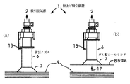
図1(a)と図1(b)は従来技術による持上げ吸引装置1の作動様式を示している。図1(a)では、持上げ吸引装置1は吸引ノズル6のゴム製シールリング7で枚葉紙8を枚葉紙パイル9から取る。そのために、吸引空気源2で生成される負圧を利用する。枚葉紙8を捕らえてから図1(b)に示す持上げ運動17が行われ、このときには吸引空気が枚葉紙8の吸着後に持上げ運動17を惹起する。このような種類の持上げ吸引装置1では、ゴム製シールリング7が枚葉紙を完全に覆わないと持上げ運動17が成立せず、これは紙が波打っているときに起こり得る。しかも重力による力の相応に正確な検出が不可能なので、二重枚葉紙または多重枚葉紙の持上げを持上げ吸引装置1のすぐ付近で確認することができない。
【0019】
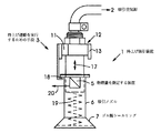
図2は本発明による持上げ吸引装置1の第1の実施形態を示している。この持上げ吸引装置では、吸着の工程が持上げの工程から分離されている。吸着は同様に、ホース15とホース止め輪16によってノズルガイド14に接続され、必要な負圧で吸引ノズル6を負荷する吸引空気源2によって行われる。しかしながら持上げ運動を実行するための手段3は、電磁式の直線運動駆動装置10によって別個に構成されている。この直線運動駆動装置は、吸引ノズル6に接続された永久磁石11からなっている。持上げ運動17は永久磁石11がコイル12を通る電流によって、磁気保持鉄13と協働しながら持上げ運動17のための相応の力で負荷されることによって惹起される。
【0020】
それと同時に電磁式の直線運動駆動装置10は、電流を測定してこれを持上げ力の目安として援用することによって、持上げ力を検出するためにも用いられる。しかしながら駆動のための電流を、永久磁石11の運動によって変化し、それによって経過した持上げ距離の検出に援用することができる信号と重ね合わせることも可能である。
【0021】
図3は第2の実施形態を示している。この実施形態では物理量を測定するための装置5が設けられている。この装置は、すでに上述した測定装置の1つであってもよいが、力センサまたは加速度センサであってもよい。測定信号20は目標値と比較されることによって評価され、対応策を開始させる。この評価は常時行ってもよく、あるいは静止摩擦といった寄生的効果をフィルタリングするために特定の時間範囲でのみ行ってもよい。この目的のために測定値をフィルタリングすることもできる。また負圧に関して、図示しない追加的な測定手段が設けられていてもよい。この実施形態はさらに吸引ノズルの下側の位置のためのストッパ18を有している。さらに重量に起因する吸引ノズル6の下降運動を支えて、持上げ運動17が負圧によってではなく持上げ運動を実行する手段3によってのみ行われるようにするためのばね19が配置されている。
【0022】
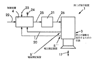
図4は、制御装置を備えた本発明の持上げ吸引装置を示している。持上げ運動17を実行するための手段3には、物理量を測定する装置5として電流測定装置5’と電圧測定装置5’’がある。測定信号20は制御装置4に供給され、制御装置はこれを1つまたは複数の入力された目標値23と比較し、もしくは先行する作業工程の目標値22と比較する。こうした目標値では多くの影響量を考慮することができ、たとえば紙の種類、紙型、紙の厚さ、あるいは使用する吸引装置の型式などを考慮することができる。たとえばボール紙を加工する場合のような極端な条件を考慮することも可能である。こうした目標値が測定した値と一致していないと、エラー信号24が発せられて制御電流25と吸引空気負荷によって修正を行い、たとえば持上げ工程が繰り返される。制御電流25は増幅器21に送られ、増幅器は相応の動作電流26を電磁式の直線運動駆動装置10のために準備する。
【0023】
図5は、本発明の方法の一例としてのフローチャートを示している。スタート27の後、第1のステップ28で、たとえば印刷されるべき紙の種類に対応する入力された目標値23としてパラメータがロードされる。ステップ29でこのパラメータに対応する負圧が送られ、枚葉紙8が吸着されて持上げ工程がスタートする。持上げ吸引装置1によって枚葉紙8を捕らえた後、負圧の測定30が行われる。この測定結果は制御装置4に伝えられ、制御装置は実際値と目標値との比較31を実行する。負圧が正確32か、過大33か、過少34かに応じて相応の次の作業ステップが実行される。正確な負圧32の場合にはステップ38で、持上げ工程がたとえばドラッグ式吸引装置への枚葉紙8の引き渡しまで続行される。ステップ39では枚葉紙の引き渡しまで待機し、次いで負圧をオフにする。それから持上げ吸引装置1は下側の位置へと移動する(ステップ40)。負圧が過大33のときは持上げ工程を終了させ、下側の位置へと移動する(ステップ35)。そして負圧を下げ(ステップ36)、ステップを繰り返す。負圧が過少のとき(矢印34)にはステップ35で同様に持上げ工程を終了させ、下側の位置へ移動する。それから負圧を高めて(ステップ37)、あらためてステップを繰り返す。
【0024】
持上げ吸引装置も方法もいずれも一例を述べたにすぎず、類似のやり方でさまざまなパラメータを検出することができ、負圧の代わりに加速度、速度、または駆動工程のその他のパラメータを検出して制御することができる。さまざまな可能性の組合せも考えられる。また相応の経験値を特性曲線としてファイルしておいて、工程の制御の基礎として役立てることも可能である。
【図面の簡単な説明】
【図1】従来技術による持上げ吸引装置とその作動様式である。
【図2】本発明による持上げ吸引装置の第1の実施形態の原理図である。
【図3】第2の実施形態である。
【図4】制御装置を備えた本発明による持上げ吸引装置である。
【図5】本発明の方法の一例としてのフローチャートである。
【符号の説明】
1 持上げ吸引装置
2 吸引空気源
3 持上げ運動を実行するための手段
4 制御装置
5 物理量を測定する装置
5’ 電流測定装置
5’’ 電圧測定装置
6 吸引ノズル
7 ゴム製シールリング
8 枚葉紙
9 枚葉紙パイル
10 電磁式の直線運動駆動装置
11 永久磁石
12 コイル
13 磁気保持鉄
14 ノズルガイド
15 ホース
16 ホース止め輪
17 持上げ運動
18 ストッパ
19 ばね
20 測定信号
21 増幅器
22 先行する作業工程の目標値
23 入力された目標値
24 エラー信号
25 制御電流
26 動作電流
27 スタート
28 パラメータがロードされるステップ
29 パラメータに対応する負圧が送られ、枚葉紙が吸着されて持上げ工程がスタートするステップ
30 負圧の測定
31 実際値と目標値との比較
32 負圧が正確
33 負圧が過大
34 負圧が過少
35 持上げ工程を終了させ、下側の位置へ移動するステップ
36 負圧を下げるステップ
37 負圧を高めるステップ
38 持上げ工程がたとえばドラッグ式吸引装置への枚葉紙の引き渡しまで続行されるステップ
39 枚葉紙の引き渡しまで待機し、次いで負圧をオフにするステップ
40 持上げ吸引装置は下側の位置へと移動するステップ[0001]
BACKGROUND OF THE INVENTION
The present invention relates to a method of operating a lifting suction device for picking up a sheet from a pile in which the sheet is adsorbed and lifted.
[0002]
The invention further relates to a lifting suction device for carrying out the above method comprising a suction air source, means for carrying out a lifting movement and a control device.
[0003]
[Prior art]
Such a lifting suction device serves to lift a sheet of paper from a pile and supply it to the machine in a paper processing machine, particularly a printing machine. From German patent specification 4012778 C1, lifting suction devices of the kind mentioned at the beginning are known. In this lifting suction device, both the holding force and the lifting motion are generated by suction air. The sheet is lifted when the suction surface is covered by the sheet. Such a type of suction device requires adjustment in accordance with the type of paper to be used each time, and such adjustment requires great fingertip sensation and test running. If this adjustment cannot be made correctly, the sheet will not be taken out, or double sheets or multiple sheets will be caught by the lifting suction device. Even after the adjustment has been made, it may lead to such a malfunction, particularly when the specific influence amount changes. Such influence amounts are waving paper, temperature, humidity, static electricity, atmospheric pressure, and the like. In part, the sheets also stick together, especially at the edges.
[0004]
[Problems to be solved by the invention]
Conventionally, as a countermeasure, it has been known to use a double-sheet inspection device that stops paper travel in the event of an error and thereby stops the machine. However, it is difficult to detect double sheets in the flow of scaly sheets. Previously known double sheet inspection devices are located just before entering the machine, which means that safety elements that switch in the event of an error give very little reaction time to stop the process. Is invited. Moreover, in many cases, the proper operation of the double sheet inspection device is not guaranteed, especially in the case of specific paper types. In this case, it may lead to the formation of a so-called bundle, that is, it may lead to the attachment of two or more sheets that may cause the machine to fail. Even if this type of double sheet inspection device can prevent machine failure, the manufacturing process will be interrupted. Yet another disadvantage of the known lifting suction device and its mode of operation is that its function progress is set stationary and cannot be flexibly adjusted or adapted to the production flow.
[0005]
It is an object of the present invention to provide a method and apparatus of the type described at the beginning for sheet feeding, for various materials, especially for various paper types, and even when there are other changes in ambient conditions. It is an improvement that is automatically stabilized and best adjusted to prevent double sheets.
[0006]
[Means for Solving the Problems]
The purpose described above is that at least one physical quantity characterizing the lifting process is detected and compared with a target value assigned to it, and when it differs from the target value, the sheet running is automatically stabilized, Countermeasures to prevent double sheets are initiated and the physical quantity is achieved by being the driving current of the lifting device.
[0008]
An advantage of the present invention is that faults in sheet travel are detected as early as possible. This is true both when the sheet is not taken out by the lifting suction device and when two or more sheets are taken at a time. With the method according to the invention and the device according to the invention, such malfunctions can be detected immediately and corresponding countermeasures can be initiated. It is possible to perform an early correction operation that does not lead to any malfunction, or it is possible to interrupt the lifting process, correct the adjustment value, and continue the paper travel immediately. This avoids interruptions in machine operation for long periods of time, and by accelerating the operation of the lifting suction device, in some cases, the lost time is recovered, so that the subsequent operation of the machine, for example the printing press, can be continued. It is possible to secure. The machine is stopped only when the sheet running correction cannot be implemented for some reason. However, even in this case, the control can generate an error signal early to stop the machine slowly, that is, without causing a failure.
[0009]
It is possible to detect various physical quantities both in terms of methods and devices. Advantageously, a physical quantity characterizing the lifting process is detected. The negative pressure can also be detected, but advantageously in addition to the physical quantities mentioned above. The lifting process is characterized by lifting force, lifting time, lifting acceleration, and lifting speed. When the lifting time is used as a basis, a known lifting force is assumed. When detecting lifting acceleration, the force due to the weight of the drive member should be taken into account. Other possibilities include detecting the lifting and sucking device process in a time-dependent manner, or detecting the delayed energy of the lifting and sucking device at the upper stopper, i.e. after carrying out the lifting movement.
[0010]
The physical quantity is detected and readjusted in comparison with the target value. The detection of physical quantities is usually aimed at confirming the force due to the weight of the detected sheet, so that larger differences than usual are always an indication that there is a malfunction that must be corrected by countermeasures as much as possible. It is. If the force due to weight has a greater downward difference than usual, it is considered that the sheet was not captured, and if there is a greater upward difference than usual, two or more sheets Leaf paper is caught. As a corresponding countermeasure, the process can be repeated. If the sheet is not caught, for example, the negative pressure is increased so that the sheet can be caught. In the case of a plurality of sheets, it is suitable for the purpose to lower the negative pressure again to lower the negative pressure and then repeat the lifting of the sheets. Of course, it is possible to take down the double and multiple sheets in different ways so that the process can continue. For this purpose, for example, a combination of a lifting suction device by an electric motor and another linear motion drive device is provided in the propulsion direction, or a cam-shaped linear motion drive device is intended to be used. It is also conceivable to provide a device for capturing multiple sheets to induce directional movement.
[0011]
In order to evaluate the detected physical quantity, it is possible to compare this physical quantity with the input target value or with the physical quantity of the work process preceding this. If there is a difference, it must be readjusted, for example, in the manner described above for negative pressure. If such a difference is detected early, it is often possible to readjust without causing a failure, even if it is a slight difference. If a failure occurs and cannot be removed, the process must be interrupted and repeated. In many cases, the correction of the physical quantity is a correction of the suction force so that the suction force accurately corresponds to the suction of the sheet. Instead of interrupting the lifting process, in the case of a plurality of sheets, it can also be removed, for example by loading with a lateral movement. The latter method should be given priority especially when a plurality of sheets are generated not because of an excessively large suction force but because the sheets are stuck together. When correction takes time, it is possible to control the travel of the sheet so that the time delay caused by the situation can be recovered.
[0012]
The aforementioned development of the method can also be taken into account by configuring the lifting suction device accordingly. These types of developments will be clearly described below by way of example only.
[0013]
In a development suitable for the purpose of the lifting suction device, it is intended that the lifting suction device is equipped with a separate device for sucking and lifting the sheets. This allows for precise and independent detection and control of both processes, thereby greatly increasing the mode of operation for the desired result compared to the mode of operation set to stationary in prior art lifting suction devices. Allows for improved fit. In particular, it makes it possible to detect and control the physical quantity characterizing the lifting process better separated from the physical quantity characterizing the adsorption process. In the separated devices for sucking and lifting sheets, it is suitable for the purpose that each device has at least one device for measuring physical quantities.
[0014]
In a particularly advantageous configuration of the lifting suction device, it is intended to be equipped with an electromagnetic linear motion drive device for lifting the sheet. This electromagnetic linear motion drive device or other drive device may also incorporate a device for measuring physical quantities. One important point is that the lifting force is detected. At this time, the lifting force can be obtained particularly well by measuring the current. Another possibility is that the process is detected in a time-dependent manner, for example by superimposing a signal on the drive current and separating this signal change corresponding to the advanced process separately. This is possible by providing a device for evaluation. In this regard, see the paper “Miniaturitremit Mitte Integre Weigmesstem” in F & M 9/97.
[0015]
In another configuration, it is intended that the lifting suction device is equipped with a piezo drive for lifting. Other drive devices are also conceivable. In this case, the drive device may be arranged or configured so that the sheet is lifted obliquely, that is, with a propulsion component. Of course, this must be taken into account accordingly when evaluating the measurement results.
[0016]
A device for detecting and adjusting the suction force may be provided in the lifting suction device. The lifting movement can be controlled independently of the suction force. It is also possible to provide means for removing multiple sheets. Furthermore, the lifting suction device can also be configured such that the travel of the sheet is accelerated by the control device so that the time delay can be recovered within a certain range by means of a separate drive device for the lifting movement. it can.
[0017]
DETAILED DESCRIPTION OF THE INVENTION
Next, embodiments of the present invention will be described with reference to the drawings.
[0018]
1 (a) and 1 (b) show the manner of operation of the lifting suction device 1 according to the prior art. In FIG. 1 (a), the lifting suction device 1 takes the sheet 8 from the sheet pile 9 with the
[0019]
FIG. 2 shows a first embodiment of the lifting suction device 1 according to the present invention. In this lifting suction device, the adsorption process is separated from the lifting process. Adsorption is likewise performed by the
[0020]
At the same time, the electromagnetic linear motion drive device 10 is also used to detect the lifting force by measuring the current and using this as a measure of the lifting force. However, it is also possible to superimpose the current for driving with a signal that is changed by the movement of the
[0021]
FIG. 3 shows a second embodiment. In this embodiment, an
[0022]
FIG. 4 shows the lifting suction device of the present invention provided with a control device. The
[0023]
FIG. 5 shows a flow chart as an example of the method of the present invention. After
[0024]
Both the lifting suction device and the method are just examples, and various parameters can be detected in a similar way, detecting acceleration, velocity or other parameters of the driving process instead of negative pressure Can be controlled. Various combinations of possibilities are also conceivable. It is also possible to file corresponding experience values as characteristic curves and use them as a basis for process control.
[Brief description of the drawings]
1 is a lifting suction device according to the prior art and its mode of operation.
FIG. 2 is a principle view of a first embodiment of the lifting suction device according to the present invention.
FIG. 3 is a second embodiment.
FIG. 4 is a lifting suction device according to the invention with a control device.
FIG. 5 is an exemplary flowchart of the method of the present invention.
[Explanation of symbols]
DESCRIPTION OF SYMBOLS 1
Claims (5)
持上げ工程を特徴づける物理量の少なくとも1つが検出されて、これに割り当てられた目標値と比較され、目標値と異なっているときには、枚葉紙走行が自動的に安定化されて、二重枚葉紙が防止される対応策が開始され、前記物理量は前記持ち上げ吸引装置の駆動電流であることを特徴とする持上げ吸引装置を作動させる方法。In a method of operating a lifting suction device that picks up a sheet of paper and picks it up from a pile,
At least one of the physical quantities characterizing the lifting process is detected and compared with a target value assigned to it, and when it is different from the target value, the sheet running is automatically stabilized and double sheets A method for operating a lifting suction device, characterized in that a countermeasure to prevent paper is started and the physical quantity is a drive current of the lifting suction device.
Applications Claiming Priority (2)
| Application Number | Priority Date | Filing Date | Title |
|---|---|---|---|
| DE19912538.4 | 1999-03-19 | ||
| DE19912538 | 1999-03-19 |
Publications (3)
| Publication Number | Publication Date |
|---|---|
| JP2000289887A JP2000289887A (en) | 2000-10-17 |
| JP2000289887A5 JP2000289887A5 (en) | 2007-03-01 |
| JP4884580B2 true JP4884580B2 (en) | 2012-02-29 |
Family
ID=7901724
Family Applications (1)
| Application Number | Title | Priority Date | Filing Date |
|---|---|---|---|
| JP2000078050A Expired - Fee Related JP4884580B2 (en) | 1999-03-19 | 2000-03-21 | Method for operating a lifting suction device |
Country Status (3)
| Country | Link |
|---|---|
| US (1) | US6349930B1 (en) |
| JP (1) | JP4884580B2 (en) |
| DE (1) | DE10009666A1 (en) |
Families Citing this family (17)
| Publication number | Priority date | Publication date | Assignee | Title |
|---|---|---|---|---|
| US6557845B2 (en) * | 2001-01-31 | 2003-05-06 | Heidelberger Druckmaschinen Ag | Sheet separating device |
| JP4673546B2 (en) * | 2002-10-25 | 2011-04-20 | ハイデルベルガー ドルツクマシーネン アクチエンゲゼルシヤフト | Flip-up mouthpiece |
| JP4000303B2 (en) * | 2003-03-25 | 2007-10-31 | 富士フイルム株式会社 | Adsorption single wafer method and adsorption single wafer apparatus |
| DE10346415A1 (en) * | 2003-10-07 | 2005-05-04 | Rovema Gmbh | Transfer device for flat objects, e.g. folded cartons, using suction head operated by drive with force control detecting contact between suction head and handled object |
| DE102005001516B4 (en) * | 2005-01-13 | 2013-04-18 | manroland sheetfed GmbH | sheet feeder |
| US7641185B2 (en) * | 2005-12-22 | 2010-01-05 | Ncr Corporation | Vacuum pick mechanisms |
| US7445205B2 (en) * | 2006-01-06 | 2008-11-04 | Xerox Corporation | Automatically variably heated airflow for separation of humid coated paper print media |
| DE102007005403A1 (en) * | 2007-02-03 | 2008-08-07 | Man Roland Druckmaschinen Ag | Sheet-separating suction device for feeder of sheet printing press, has drive device including stroke length adjusting device for fixing suction position by adjustment of length of stroke of cup along vertical running path |
| JP4691534B2 (en) * | 2007-09-07 | 2011-06-01 | アキヤマインターナショナル株式会社 | Soccer equipment for the sheet feeding section of a sheet-fed press |
| US8709332B2 (en) | 2011-07-20 | 2014-04-29 | Nike, Inc. | Thermoforming sheet loading apparatus and method |
| US8727336B2 (en) * | 2011-10-31 | 2014-05-20 | Ncr Corporation | Condition determining |
| JP6486720B2 (en) * | 2015-03-03 | 2019-03-20 | コマツ産機株式会社 | Material separation device and material separation method |
| CN105523402B (en) * | 2015-10-23 | 2017-12-22 | 苏州天裁纺织工艺品有限公司 | A kind of ear muff circle cladding travel mechanism |
| CN106808388A (en) * | 2017-03-01 | 2017-06-09 | 济南大学 | A kind of micro- curved surface sucking disk type fixing seat of portable minisize |
| CN107322552B (en) * | 2017-08-25 | 2020-10-16 | 芜湖腾飞信息科技有限公司 | Safety helmet containing box for construction |
| CN109720432A (en) * | 2019-03-04 | 2019-05-07 | 安徽理工大学 | A kind of adjustable Acetabula device of suction |
| DE102023122270B3 (en) * | 2023-08-21 | 2024-06-20 | Heidelberger Druckmaschinen Aktiengesellschaft | Suction head of a sheet feeder |
Family Cites Families (14)
| Publication number | Priority date | Publication date | Assignee | Title |
|---|---|---|---|---|
| US4585222A (en) | 1982-03-01 | 1986-04-29 | Sharp Kabushiki Kaisha | Sheet paper attracting system |
| US4591140A (en) | 1983-03-12 | 1986-05-27 | Agfa-Gevaert Aktiengesellschaft | Arrangement for separating and transporting uppermost sheets of a stack of sheets or sheet-like objects |
| JPS6478639A (en) * | 1988-08-30 | 1989-03-24 | Matsutani Seisakusho | Bending method for suture needle |
| US5033730A (en) * | 1990-02-28 | 1991-07-23 | Sri International | Variable position vacuum article pickup apparatus |
| DE4012778C1 (en) | 1990-04-21 | 1991-05-29 | Heidelberger Druckmaschinen Ag, 6900 Heidelberg, De | |
| JP2641595B2 (en) * | 1990-05-07 | 1997-08-13 | 富士写真フイルム株式会社 | Sheet-fed sheet method |
| JPH05116809A (en) * | 1991-10-29 | 1993-05-14 | Sharp Corp | Pneumatic paper feeder |
| JPH05178480A (en) * | 1991-12-25 | 1993-07-20 | Ricoh Co Ltd | Air adsorption separation device and separation method thereof |
| JPH06219578A (en) * | 1993-01-21 | 1994-08-09 | Sharp Corp | Air feeding device |
| JPH07187418A (en) * | 1993-12-27 | 1995-07-25 | T O P:Kk | Automatic supplyer for protection material for tile stacked on pallet |
| JP2887725B2 (en) * | 1994-03-04 | 1999-04-26 | 日産ディーゼル工業株式会社 | Automatic sheet material feeder |
| JP3819971B2 (en) * | 1996-08-26 | 2006-09-13 | 三菱重工業株式会社 | Feed adjustment device for printing press |
| JPH1077130A (en) * | 1996-09-04 | 1998-03-24 | Canon Inc | Sheet feeding apparatus and image forming apparatus |
| JPH10236677A (en) * | 1997-02-28 | 1998-09-08 | Canon Inc | Sheet feeding device and recording / reading device using the same |
-
2000
- 2000-02-29 DE DE10009666A patent/DE10009666A1/en not_active Withdrawn
- 2000-03-20 US US09/531,339 patent/US6349930B1/en not_active Expired - Fee Related
- 2000-03-21 JP JP2000078050A patent/JP4884580B2/en not_active Expired - Fee Related
Also Published As
| Publication number | Publication date |
|---|---|
| JP2000289887A (en) | 2000-10-17 |
| US6349930B1 (en) | 2002-02-26 |
| DE10009666A1 (en) | 2000-09-21 |
Similar Documents
| Publication | Publication Date | Title |
|---|---|---|
| JP4884580B2 (en) | Method for operating a lifting suction device | |
| US8210519B2 (en) | Sheet feeding apparatus and image forming apparatus | |
| US6561509B2 (en) | Monitoring apparatus for the sheet feed to a sheet-processing machine, and method of monitoring the sheet stream structure/the sheet stream | |
| JP2019531919A (en) | Horizontal registration of sheets | |
| CN205416688U (en) | Detect device of printing marker alignment | |
| CN112875354A (en) | Sheet feeding device and image forming apparatus | |
| JP5907853B2 (en) | Method and apparatus for forming auxiliary piles | |
| EP2402271A2 (en) | Sheet handling apparatus and sheet handling method | |
| US5348286A (en) | Device for controlling an individual separation of sheets incorrectly separated from a sheet pile | |
| CN101962128A (en) | Method and device for operating a stack lifting device | |
| US6418977B1 (en) | Yarn processing system with weft yarn tension regulation | |
| JP5192886B2 (en) | Method and apparatus for individualizing plates in a stack | |
| DE102012003270A1 (en) | Device for transporting and / or aligning a sheet | |
| US7478807B2 (en) | Method for conveying a sheet and apparatus for carrying out the method | |
| JP2007277008A (en) | Active sheet induction/sheet guide element | |
| JP7412147B2 (en) | How to replace piles formed from sheets in feeders | |
| JP3819971B2 (en) | Feed adjustment device for printing press | |
| JP5670636B2 (en) | Recording device | |
| JP2013023332A (en) | Sheet feeder and collator having the same | |
| CZ200852A3 (en) | Suction separation device for rotary printing presses | |
| JPS6228056B2 (en) | ||
| EP3122673B1 (en) | Device and method for feeding papers | |
| US7611143B2 (en) | Sheet separating apparatus and method | |
| JP4575840B2 (en) | Paper feeder | |
| US20190224961A1 (en) | Method of controlling the clamping of a plate in a printing press |
Legal Events
| Date | Code | Title | Description |
|---|---|---|---|
| A521 | Request for written amendment filed |
Free format text: JAPANESE INTERMEDIATE CODE: A523 Effective date: 20070111 |
|
| A621 | Written request for application examination |
Free format text: JAPANESE INTERMEDIATE CODE: A621 Effective date: 20070111 |
|
| RD03 | Notification of appointment of power of attorney |
Free format text: JAPANESE INTERMEDIATE CODE: A7423 Effective date: 20070111 |
|
| A131 | Notification of reasons for refusal |
Free format text: JAPANESE INTERMEDIATE CODE: A131 Effective date: 20090819 |
|
| A521 | Request for written amendment filed |
Free format text: JAPANESE INTERMEDIATE CODE: A523 Effective date: 20091119 |
|
| A131 | Notification of reasons for refusal |
Free format text: JAPANESE INTERMEDIATE CODE: A131 Effective date: 20100310 |
|
| A521 | Request for written amendment filed |
Free format text: JAPANESE INTERMEDIATE CODE: A523 Effective date: 20100525 |
|
| A131 | Notification of reasons for refusal |
Free format text: JAPANESE INTERMEDIATE CODE: A131 Effective date: 20101124 |
|
| A521 | Request for written amendment filed |
Free format text: JAPANESE INTERMEDIATE CODE: A523 Effective date: 20110217 |
|
| A131 | Notification of reasons for refusal |
Free format text: JAPANESE INTERMEDIATE CODE: A131 Effective date: 20110713 |
|
| A521 | Request for written amendment filed |
Free format text: JAPANESE INTERMEDIATE CODE: A523 Effective date: 20111012 |
|
| TRDD | Decision of grant or rejection written | ||
| A01 | Written decision to grant a patent or to grant a registration (utility model) |
Free format text: JAPANESE INTERMEDIATE CODE: A01 Effective date: 20111108 |
|
| A01 | Written decision to grant a patent or to grant a registration (utility model) |
Free format text: JAPANESE INTERMEDIATE CODE: A01 |
|
| A61 | First payment of annual fees (during grant procedure) |
Free format text: JAPANESE INTERMEDIATE CODE: A61 Effective date: 20111207 |
|
| FPAY | Renewal fee payment (event date is renewal date of database) |
Free format text: PAYMENT UNTIL: 20141216 Year of fee payment: 3 |
|
| R150 | Certificate of patent or registration of utility model |
Free format text: JAPANESE INTERMEDIATE CODE: R150 |
|
| R250 | Receipt of annual fees |
Free format text: JAPANESE INTERMEDIATE CODE: R250 |
|
| R250 | Receipt of annual fees |
Free format text: JAPANESE INTERMEDIATE CODE: R250 |
|
| R250 | Receipt of annual fees |
Free format text: JAPANESE INTERMEDIATE CODE: R250 |
|
| LAPS | Cancellation because of no payment of annual fees |