JP4879193B2 - System log management support apparatus and system log management support method - Google Patents
System log management support apparatus and system log management support method Download PDFInfo
- Publication number
- JP4879193B2 JP4879193B2 JP2008003647A JP2008003647A JP4879193B2 JP 4879193 B2 JP4879193 B2 JP 4879193B2 JP 2008003647 A JP2008003647 A JP 2008003647A JP 2008003647 A JP2008003647 A JP 2008003647A JP 4879193 B2 JP4879193 B2 JP 4879193B2
- Authority
- JP
- Japan
- Prior art keywords
- system log
- information
- data
- key
- record
- Prior art date
- Legal status (The legal status is an assumption and is not a legal conclusion. Google has not performed a legal analysis and makes no representation as to the accuracy of the status listed.)
- Expired - Fee Related
Links
Images


Landscapes
- Debugging And Monitoring (AREA)
Description
この発明は、ネットワークシステムのログ情報を管理するシステムログ管理支援装置およびシステムログ管理支援方法に関するものである。 The present invention relates to a system log management support apparatus and system log management support method for managing log information of a network system.
企業の内部統制によって、IT(Information Technology)システムの監査が重要となっている。内部統制では、ITシステムを用いたユーザによる業務プロセスの実行・操作履歴をシステムログとして記録し、このシステムログをセキュリティ事故発生時、障害対応時などの分析に利用する。そのため、企業では、システムログを記録・保管し、管理しなければならない。システムログの構成は、基本的に、「いつ、どこで、誰が、何を、どのような操作をしたか」という内容からなるものであり、ITシステムによって出力データは異なるものである。また、多くのユーザが利用するITシステムにおいては、膨大な量のシステムログが出力され、さらに、企業の内部統制の強化によって、システムログは、長期にわたって保管しなければならなくなっている。そのため、システムログを記録し、保管するための記憶装置の記憶容量がすぐにいっぱいになってしまうという問題点がある。 IT (Information Technology) system auditing is important due to internal control of companies. In internal control, the execution / operation history of a business process by a user using an IT system is recorded as a system log, and this system log is used for analysis when a security accident occurs or when a failure is dealt with. Therefore, companies must record, store, and manage system logs. The structure of the system log basically consists of the contents of “when, where, who, what, and what operation”, and the output data differs depending on the IT system. Further, in an IT system used by many users, an enormous amount of system logs are output, and further, system logs must be stored for a long time due to strengthening of internal control of a company. For this reason, there is a problem that the storage capacity of the storage device for recording and storing the system log becomes full immediately.
ところで、従来からログデータを編集するログデータ編集方法は提案されており、その中の一つのログデータ編集方法には、不要または古いシステムログを削除したり、時間ごとにシステムログを集約してその件数だけを表示したりするなど、システムログの効率的な編集によって、データ容量を抑える技術が開示されている(たとえば、特許文献1参照)。 By the way, a log data editing method for editing log data has been proposed, and one of the log data editing methods includes deleting unnecessary or old system logs or consolidating system logs every hour. A technique for reducing the data capacity by efficiently editing the system log such as displaying only the number of cases is disclosed (for example, see Patent Document 1).
しかしながら、上記従来の技術によれば、本来分析に必要なシステムログが削除されていたり、詳細データについての欠落が存在したりするため、完全な形のシステムログを必要とする内部統制を考慮したシステムログの容量削減方法ではない。また、従来の技術では、編集方法によっては、想定外のシステムログデータを編集してしまう可能性がある。つまり、従来の技術では、内部統制用のシステムログ分析時に不備が生じてしまうという問題点があった。 However, according to the above-mentioned conventional technology, since the system log originally required for analysis is deleted or there is a lack of detailed data, internal control that requires a complete system log is considered. It is not a method for reducing the system log capacity. Further, in the conventional technique, there is a possibility that unexpected system log data may be edited depending on the editing method. In other words, the conventional technology has a problem that deficiencies occur when analyzing the system log for internal control.
この発明は、上記に鑑みてなされたもので、ITシステムで記録・保管されるシステムログについて、その容量を削減して保存することができるとともに、元の完全な形のシステムログを再現することができるシステムログ管理支援装置およびシステムログ管理支援方法を得ることを目的とする。 The present invention has been made in view of the above, and it is possible to reduce the capacity of a system log recorded / stored in an IT system, and to reproduce the original complete system log. An object of the present invention is to obtain a system log management support apparatus and system log management support method capable of performing the above.
上記目的を達成するため、この発明にかかるシステムログ管理支援装置は、所定の出力キーからなるシステムログの複数の前記出力キーのうち、ユーザによって選択される所定の割合以上同じ内容のデータが出現する出力キーからなる冗長キー、および該冗長キーに対応するデータの組み合わせを識別する識別キーで構成される集約情報と、前記冗長キー以外の出力キー、および前記識別キーを用いて前記集約情報中のレコードと関連付けを行う関連付けキーで構成されるデータ情報とに、前記システムログ中のレコードを分割した正規化システムログ情報を生成して、前記システムログに記録されるデータ量を削減する正規化条件設定反映手段を備えることを特徴とする。 In order to achieve the above object, the system log management support apparatus according to the present invention has the appearance of data having the same content over a predetermined ratio selected by the user among the plurality of output keys of the system log composed of predetermined output keys. redundant key consisting output keys for, and該冗aggregated information consists of identifying key identifying a combination of data corresponding to length key, the aggregation by using the output key other than the redundant key, and the identification key Normalized system log information is generated by dividing the records in the system log into data information composed of association keys for associating with records in the information to reduce the amount of data recorded in the system log Normalization condition setting reflection means is provided.
この発明によれば、同じ内容が繰り返し出力される出力項目を集約して、システムログの内容を編集するようにしたので、システムログの容量を削減して保存することができるとともに、元の完全な形のシステムログを再現することができるという効果を有する。 According to the present invention, since the output items in which the same contents are repeatedly output are aggregated and the contents of the system log are edited, the capacity of the system log can be reduced and saved, and the original complete System log can be reproduced.
以下に添付図面を参照して、この発明にかかるシステムログ管理支援装置およびシステムログ管理支援方法の好適な実施の形態を詳細に説明する。なお、この実施の形態によりこの発明が限定されるものではない。 Exemplary embodiments of a system log management support apparatus and a system log management support method according to the present invention will be explained below in detail with reference to the accompanying drawings. Note that the present invention is not limited to the embodiments.
実施の形態.
図1は、この発明にかかるシステムログ管理支援装置が適用されるシステムの構成の一例を模式的に示す図である。このシステムは、組織が所有するITシステム10と、システムログ管理支援装置20と、がネットワーク30を介して接続され、システムログ管理支援装置20には、ネットワークなどの通信回線40を介してシステムログ退避用記憶装置50が接続される。
Embodiment.
FIG. 1 is a diagram schematically showing an example of a system configuration to which a system log management support apparatus according to the present invention is applied. In this system, an
ITシステム10は、たとえば企業などの組織内で構築された組織内ネットワークであり、図示しないが、組織内で管理する電子データや組織構成員に対して提供するサービスを格納したり、外部ネットワークへのアクセスを制御したりするサーバ装置と、組織構成員が所有する情報処理端末と、組織構成員による情報処理端末を介したサーバ装置へのアクセスなどのログ情報であるシステムログ11を記録し、管理するシステムログ収集装置と、を備える。
The
システムログ管理支援装置20は、ITシステム10のシステムログ収集装置で収集されたシステムログ11の管理を支援する。より詳しくは、ITシステム10で収集したシステムログ11について、そのサイズ(容量)を小さくするとともに、後にセキュリティ事故発生時や障害対応時などの分析の際に元の完全な形のシステムログ11に戻すことができるようにシステムログ11を正規化して正規化システムログとして保存する。また、システムログ退避用記憶装置50は、システムログ管理支援装置20で管理対象となっている正規化システムログを退避(バックアップ)するための装置である。
The system log
つぎに、システムログ管理支援装置20の詳細な構成について説明する。図2は、この発明にかかるシステムログ管理支援装置の機能構成を模式的に示すブロック図である。このシステムログ管理支援装置20は、システムログ取得部21と、表示部22と、表示処理部23と、入力部24と、正規化条件設定反映部25と、正規化システムログ情報格納部26と、検索部27と、退避部28と、これらの各処理部を制御する制御部29と、を備える。このシステムログ管理支援装置20は、たとえばパーソナルコンピュータなどの情報処理装置によって構成することができる。
Next, a detailed configuration of the system log
システムログ取得部21は、対象となるITシステム10からシステムログを取得し、一時的に記憶する。図1では、ITシステム10とシステムログ管理支援装置20とは、ネットワーク30を介して接続されているので、ITシステム10のシステムログ収集装置からネットワーク30を介してシステムログ11を受信して取得することができる。この場合には、システムログ取得部21は、通信機能と、通信機能で受信したシステムログ11を一時的に記憶する記憶機能と、によって構成されることになる。
The system log acquisition unit 21 acquires a system log from the
また、システムログをCD(Compact Disk)−R/RW(Recordable/Rewritable)、DVD(Digital Versatile Disk)−R/RW、DVD+R/RW、DVD−RAM(Random Access Memory)、メモリカードなどの記録媒体に記録したものを、読込むことも可能である。この場合には、システムログ取得部21は、記録媒体に記録されたシステムログを読取る記録媒体読取処理機能によって構成される。 The system log is recorded on a recording medium such as a CD (Compact Disk) -R / RW (Recordable / Rewritable), a DVD (Digital Versatile Disk) -R / RW, a DVD + R / RW, a DVD-RAM (Random Access Memory), or a memory card. It is also possible to read what is recorded in In this case, the system log acquisition unit 21 is configured by a recording medium reading processing function that reads the system log recorded on the recording medium.
表示部22は、液晶表示装置などの表示装置によって構成される。また、表示処理部23は、表示部22に所定の表示画面を表示する。表示処理部23は、たとえば、取得したシステムログを表示部22に表示したり、取得したシステムログの正規化を行う際の正規化設定画面を表示部22に表示したり、正規化されたシステムログ(以下、正規化システムログという)を用いて検索を行うための検索画面を表示部22に表示したりする処理を行う。
The
入力部24は、キーボードやマウスなどの入力装置によって構成され、該システムログ管理支援装置20のユーザ(管理者)との間の入力インタフェースである。この入力部24を介して、取得したシステムログの正規化を行う正規化条件、検索条件、システムログ退避用記憶装置50への正規化されたシステムログの退避命令などのユーザからの指示が入力される。
The input unit 24 includes an input device such as a keyboard and a mouse, and is an input interface with a user (administrator) of the system log
ここで、正規化条件は、表示部22に表示されたシステムログを閲覧しているユーザが重複して出現することが多い(所定の割合以上で出現する)データを有する項目を選択することによって、設定される。なお、この明細書で、正規化とは、システムログを、冗長となりやすいデータからなる集約テーブルと、それ以外のデータからなるデータテーブルとに分けることをいうものとする。以下に示す例では、正規化条件の設定は、システムログから集約テーブルとデータテーブルとを作成するための項目を設定することをいう。
Here, the normalization condition is obtained by selecting an item having data that frequently appears in duplicate (appears at a predetermined ratio or more) as a user browsing the system log displayed on the
正規化条件設定反映部25は、入力部24からユーザによって入力された正規化条件に基づいて、システムログ取得部21で取得したシステムログを編集して正規化システムログ情報を作成し、作成した正規化システム情報を正規化システムログ情報格納部26に格納する。具体的には、正規化条件設定反映部25は、システムログのレコードを順に読み込み、ユーザによって設定された正規化条件の内容に基づいた項目からなる集約テーブル(特許請求の範囲の集約情報に対応する)とデータテーブル(特許請求の範囲のデータ情報に対応する)とを作成し、データテーブルの各レコードを集約テーブルのいずれかのレコードと関連付けを行って、正規化システムログ情報を作成する。
The normalization condition setting reflection unit 25 creates the normalized system log information by editing the system log acquired by the system log acquisition unit 21 based on the normalization condition input by the user from the input unit 24 The normalized system information is stored in the normalized system log
検索部27は、入力部24からユーザによって入力された検索条件に基づいて、正規化システムログ情報から検索を行う。また、退避部28は、入力部24からユーザによって入力された退避命令に基づいて、正規化システムログ情報格納部26内の正規化システムログ情報をテキストファイル化して、システムログ退避用記憶装置50に退避する。なお、システムログ退避用記憶装置50へ退避する正規化システムログのファイル形式として、CSV(Comma Separated Value)形式を用いることができる。このCSV形式で退避することで、正規化システムログのシステムログ管理支援装置20への再度のインポートが可能となる。また、退避部28は、正規化システムログ情報格納部26中の退避された正規化システムログ情報のうち、対応するデータテーブルに含まれるレコードのみを削除する。これは、集約テーブルのレコードは、データテーブルのレコードが集約テーブルの識別子を用いて関連付けされている可能性が想定されるため、集約テーブルのレコードは削除しない方がよいためである。
The search unit 27 performs a search from the normalized system log information based on the search condition input by the user from the input unit 24. Further, the save unit 28 converts the normalized system log information in the normalized system log
つぎに、このような構成のシステムログ管理支援装置20におけるシステムログ管理支援方法について、より具体的には、正規化条件設定処理、正規化システムログ作成処理、検索処理および退避処理について、説明する。
Next, the system log management support method in the system log
(正規化条件設定処理)
システムログ管理支援装置のユーザは、システムログの正規化処理を実行する前に、取得したシステムログを閲覧し、集約テーブルに分類する項目と、データテーブルに分類する項目と、を分ける正規化条件の設定を行う。集約テーブルに分類する項目は、システムログ中に所定の頻度で同じ内容が出現する項目であり、データテーブルに分類する項目は、その他の項目である。この項目の分類は、ユーザの判断によって行われる。
(Normalization condition setting process)
The user of the system log management support apparatus browses the acquired system log before executing the normalization processing of the system log, and normalization conditions for separating the items classified into the aggregation table and the items classified into the data table Set up. Items classified in the aggregation table are items in which the same content appears in the system log at a predetermined frequency, and items classified in the data table are other items. The classification of this item is performed based on the user's judgment.
図3は、システムログとして収集する項目の一例を示す図である。このシステムログは、たとえば図1のITシステム10で、図示しないシステムログ収集装置が収集するシステムログ11の内容を示す項目である。ここでは、「ログの種類」、「イベントID」、ITシステム10の組織構成員が情報処理端末を介してアクセスしたサーバ装置である「マシン名」、マシン名に対応するサーバ装置にアクセスした組織構成員を示す「ユーザ名」、監査の結果を示す「監査」、操作の内容を示す「操作」、組織構成員がアクセスした日時を示す「日時」、および組織構成員がアクセスしたサーバ装置上のファイルの位置である「パス」を、システムログの項目として含むものとする。
FIG. 3 is a diagram illustrating an example of items collected as a system log. This system log is an item indicating the contents of the system log 11 collected by a system log collection device (not shown) in the
図4は、システムログデータの一例を示す図である。このシステムログデータは、1つの行がITシステム10で収集された1つのレコードを示しており、図3に示される項目に対応する内容がカンマで区切られて配置されている。
FIG. 4 is a diagram illustrating an example of system log data. In this system log data, one line indicates one record collected by the
管理者は、たとえば図4に示されるシステムログデータを表示部22上に表示させて、重複する内容が多いと判断される項目を冗長キーとして選択する。一般的には、あるキー(項目)に対応するデータが所定の割合以上出現する場合に、そのキーを冗長キーとして選択する。この図4では、データ「FILE」に対応する項目「ログの種類」と、データ「560」に対応する項目「イベントID」と、データ「Server-1」に対応する項目「マシン名」と、データ「成功の監査/失敗の監査」に対応する項目「監査」が繰り返し出現する頻度が高い。そのため、ここでは管理者が冗長キーとして、たとえば「ログの種類」、「イベントID」、「マシン名」および「監査」の各項目(キー)を入力部24を介して選択したものとする。
For example, the administrator displays the system log data shown in FIG. 4 on the
その後、正規化条件設定反映部25は、選択された冗長キーの内容と、選択されなかった冗長キー以外の内容とを取得し、冗長キーに基づいて集約テーブルを作成し、冗長キー以外のキーに基づいてデータテーブルを作成するSQL文を生成し、正規化システムログ情報格納部26に、集約テーブルとデータテーブルとを作成する。
Thereafter, the normalization condition setting reflection unit 25 acquires the content of the selected redundant key and the content other than the redundant key that was not selected, creates an aggregation table based on the redundant key, and generates a key other than the redundant key. An SQL statement for creating a data table is generated based on the above, and an aggregation table and a data table are created in the normalized system log
図5は、生成された集約テーブルの一例を示す図であり、図6は、生成されたデータテーブルの一例を示す図である。図5に示される集約テーブルは、ユーザが設定した冗長キーを項目とし、さらに、これらの項目に入力される内容の組み合わせ(レコード)を一意に識別するための識別子である「id」が項目として付加されている。なお、集約テーブルに格納されるレコードには、各項目の内容が全く同じものについては記録されない。また、以上のようにして、ユーザによって選択された図5の集約テーブルの項目が正規化条件となる。 FIG. 5 is a diagram illustrating an example of the generated aggregation table, and FIG. 6 is a diagram illustrating an example of the generated data table. In the aggregation table shown in FIG. 5, the redundant key set by the user is an item, and “id” that is an identifier for uniquely identifying a combination (record) of contents input to these items is an item. It has been added. In addition, the records stored in the aggregation table are not recorded when the contents of each item are exactly the same. Further, the items in the aggregation table of FIG. 5 selected by the user as described above become the normalization conditions.
また、図6に示されるデータテーブルは、冗長キーとして選択されなかったその他のキーである「ユーザ名」、「操作」、「日時」および「パス」を項目とし、さらに、これらの項目に入力される各レコードを、対応する集約テーブルのレコードと関連付けするための「集約テーブルのid」が項目として付加されている。以上によって、正規化条件設定処理が終了する。 In addition, the data table shown in FIG. 6 includes “user name”, “operation”, “date / time”, and “pass”, which are other keys not selected as redundant keys, as items, and inputs to these items. The “aggregation table id” for associating each record to the corresponding aggregation table record is added as an item. Thus, the normalization condition setting process ends.
(正規化システムログ作成処理)
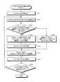
図7は、システムログの正規化処理手順の一例を示すフローチャートである。まず、ユーザによってシステムログの正規化処理の実行が入力部24を介して指示されると、システムログ取得部21は、ITシステム10からネットワーク30を介してまたは記録媒体からシステムログを取り込む(ステップS11)。ついで、正規化条件設定反映部25は、システムログ取得部21で取り込まれたシステムログ中の1行(1レコード)を読込む(ステップS12)。このレコードを以下では、元レコードという。ここでは、図4の行101に示される元レコードが選択されたものとする。
(Normalized system log creation process)
FIG. 7 is a flowchart illustrating an example of a normalization process procedure of the system log. First, when the execution of system log normalization processing is instructed by the user via the input unit 24, the system log acquisition unit 21 captures the system log from the
その後、正規化条件設定反映部25は、元レコード中の冗長キーすなわち集約テーブルの項目に対応する値が、集約テーブルに格納されているレコードに一致するものがあるか否かを判定する(ステップS13)。 Thereafter, the normalization condition setting reflection unit 25 determines whether or not there is a value corresponding to the redundant key in the original record, that is, the value corresponding to the item in the aggregation table, in the record stored in the aggregation table (Step S1). S13).
元レコード中の冗長キーに対応する値が、集約テーブルのレコードと一致しない場合(ステップS13でNoの場合)には、正規化条件設定反映部25は、冗長キーに対応するデータをレコードとして、このレコードを識別する「id」を付与して集約テーブルに格納する(ステップS14)。その後、ステップS12で読み込んだ元レコードに、ステップS14で集約テーブルに格納したidを付加する(ステップS15)。 When the value corresponding to the redundant key in the original record does not match the record in the aggregation table (in the case of No in step S13), the normalization condition setting reflecting unit 25 uses the data corresponding to the redundant key as a record. “Id” for identifying this record is assigned and stored in the aggregation table (step S14). Thereafter, the id stored in the aggregation table in step S14 is added to the original record read in step S12 (step S15).
たとえば、システムログ中の元レコードが最初の1行(1レコード)の場合、つまり図4の行101に示される元レコードが選択された場合には、図5に示されるように、集約テーブルにはレコードが格納されていない状態にある。そこで、正規化条件設定反映部25は、元レコード中から冗長キーに対応するデータを取得し、idを付して集約テーブルに格納する。図8−1は、図5の集約テーブルにデータが格納された状態の一例を示す図である。つまり、図4の行101の元レコード中のログの種類に対応する「FILE」、イベントIDに対応する「560」、マシン名に対応する「Server-1」、監査に対応する「成功の監査」からなるデータにidとして「001」を付して、集約テーブルに格納する。その後、図4の行101の元レコードにidを付加する。図8−2は、元レコードに、idが付与された状態を示す図である。ここでは、図4の行101の元レコードの末尾にid「001」が付されている。
For example, when the original record in the system log is the first line (one record), that is, when the original record shown in
また、正規化条件設定反映部25は、ステップS13で元レコード中の冗長キーに対応する値が、集約テーブルのレコードと一致する場合(ステップS13でYesの場合)には、一致した集約テーブル中のレコードに付されたidを、元レコードに付加する(ステップS16)。 In addition, when the value corresponding to the redundant key in the original record matches the record in the aggregation table in Step S13 (in the case of Yes in Step S13), the normalization condition setting reflection unit 25 The id attached to the record is added to the original record (step S16).
たとえば、集約テーブルが、図8−1のように既にレコードが登録されている場合を例に挙げると、図4の行101に示される元レコードの冗長キーは、ログの種類=「FILE」、イベントID-=「560」、マシン名=「Server-1」、監査=「成功の監査」であるので、図8−1の集約テーブル中の行111のレコードに対応する。そこで、正規化条件設定反映部25は、図8−2に示されるように、行111のレコードのid「001」を元レコードの末尾に付加する。
For example, in the case where the record is already registered in the aggregation table as shown in FIG. 8A, the redundant key of the original record shown in the
ステップS15またはステップS16の後、正規化条件設定反映部25は、元レコードから冗長キーに対応するデータを削除し(ステップS17)、データテーブルにレコードを格納する(ステップS18)。 After step S15 or step S16, the normalization condition setting reflection unit 25 deletes the data corresponding to the redundant key from the original record (step S17), and stores the record in the data table (step S18).
図8−3は、データテーブルにレコードを格納した状態の一例を示す図である。図8−2に示されるデータから冗長キーを削除した内容が、図8−3に示されるように、データテーブルに格納される。 FIG. 8C is a diagram illustrating an example of a state where records are stored in the data table. The contents obtained by deleting the redundant key from the data shown in FIG. 8-2 are stored in the data table as shown in FIG. 8-3.
そして、正規化条件設定反映部25は、システムログ中の元レコードをすべて読み込んだか否かを判定する(ステップS19)。システムログ中の元レコードをすべて読み込んでいない場合(ステップS19でNoの場合)には、ステップS12へと戻り、システムログ中の元レコードをすべて読込むまで上述した処理が繰り返し実行される。また、システムログ中の元レコードをすべて読み込んだ場合(ステップS19でYesの場合)には、正規化システムログ作成処理が終了する。 Then, the normalization condition setting reflection unit 25 determines whether all the original records in the system log have been read (step S19). If all the original records in the system log have not been read (No in step S19), the process returns to step S12, and the above-described processing is repeatedly executed until all the original records in the system log are read. When all the original records in the system log have been read (Yes in step S19), the normalized system log creation process ends.
図8−4は、図3から作成される集約テーブルの一例を示す図であり、図8−5は、図3から作成されるデータテーブルの一例を示す図である。図3に示されるシステムログから、図8−4のように2つのレコードを含む集約テーブルと、図8−5のように5つのレコードを含むデータテーブルと、からなる正規化システムログが作成される。 8-4 is a diagram illustrating an example of an aggregation table created from FIG. 3, and FIG. 8-5 is a diagram illustrating an example of a data table created from FIG. From the system log shown in FIG. 3, a normalized system log including an aggregate table including two records as shown in FIG. 8-4 and a data table including five records as shown in FIG. 8-5 is created. The
(システムログの検索処理)
正規化システムログ情報格納部26に格納された正規化システムログを用いて、ユーザからの検索指示によって、検索が行われる。図9は、検索画面の一例を示す図である。検索を行いたいときには、ユーザによる入力部24からの検索指示によって、表示処理部23は図9のような検索画面150を表示部22上に表示させる。この検索画面150は、検索キーを指定する検索キー指定領域151と、検索条件を入力する検索条件入力領域152と、検索の実行を指示する「検索」ボタン154と、を備える。
(System log search processing)
A search is performed according to a search instruction from the user using the normalized system log stored in the normalized system log
検索キー指定領域151は、たとえばリストボックスで構成され、この中にシステムログ(正規化システムログ情報)の項目が予めリスト形式で格納されており、ユーザがリスト中から検索したい項目を検索キーとして選択する。また、検索条件入力領域152は、たとえばテキストボックスで構成され、ユーザが入力部24を介して検索キーに対して検索したい条件(キーワード)が入力される領域である。これらの項目のうち未入力のものは、NULLとする。また、検索条件入力領域152内の各キーワード間のAND検索やOR検索を指定することもできるし、各条件間の検索方式として検索方式選択領域153でAND検索やOR検索を選択することも可能である。さらに、「検索」ボタン154は、検索キー指定領域151と検索条件入力領域152と検索方式選択領域153に入力された内容を、正規化システムログ情報を用いて検索する。
The search
つぎに、検索処理方法について説明する。ユーザによって入力された検索キーが、集約テーブルに含まれる項目か、データテーブルに含まれる項目かに分けた後、それぞれの検索キーにキーワードが含まれるレコードについて、分類されたテーブル内から検索する。その後、それぞれのテーブルの検索結果を結合して、集約テーブルのidが同じである列のみを残し、元の形のシステムログに復元する。 Next, a search processing method will be described. After the search key input by the user is classified into an item included in the aggregation table or an item included in the data table, a record including a keyword in each search key is searched from the classified table. Thereafter, the search results of the respective tables are combined to leave only the columns having the same id of the aggregate table, and are restored to the original system log.
さらに具体的な検索処理の方法について説明する。図10は、検索処理の手順の具体例を示す図である。ここでは、検索キーとして「日時」が選択され、キーワードとして「2007/09/30」が入力されたものとする。つまり、日時が「2007/09/30」であるシステムログを抽出するように検索指示が出されたものとする。 Further, a specific search processing method will be described. FIG. 10 is a diagram illustrating a specific example of the procedure of the search process. Here, “date and time” is selected as the search key, and “2007/09/30” is input as the keyword. That is, it is assumed that a search instruction is issued so as to extract a system log whose date is “2007/09/30”.
検索部27は、日時キーはデータテーブルに含まれるため、図8−5のデータテーブルを検索対象とし(ステップS101)、データテーブルの日時キーにキーワード「2007/09/30」が含まれるレコードを検索し、抽出する(ステップS102)。ついで、データテーブルを用いた検索結果と、集約テーブルとを結合し(ステップS103)、結合結果を取得する(ステップS104)。その後、結合結果中の集約テーブルのidが同じである行(レコード)を抽出し(ステップS105)、idを削除するとともに、所定の順序にレコード内の各データの並べ変えを行って成形を行い、元のシステムログの形式で検索結果が得られる(ステップS106)。検索部27は、この検索結果を表示処理部23に渡し、表示処理部23で表示部22に出力する。
Since the date / time key is included in the data table, the search unit 27 searches the data table in FIG. 8-5 (step S101), and records the date / time key in the data table including the keyword “2007/09/30”. Search and extract (step S102). Next, the search result using the data table and the aggregate table are combined (step S103), and the combined result is acquired (step S104). Thereafter, a row (record) having the same id in the aggregation table in the join result is extracted (step S105), the id is deleted, and each data in the record is rearranged in a predetermined order to perform shaping. The search result is obtained in the original system log format (step S106). The search unit 27 passes this search result to the display processing unit 23, and the display processing unit 23 outputs the search result to the
なお、ここで説明した検索処理では、集約テーブルとデータテーブルの個々のテーブルで検索キーのキーワードについて検索を行った後、両者を結合して元の形を有するシステムログの検索結果を得ていたが、最初に集約テーブルとデータテーブルの結合を行い、結合結果中の集約テーブルのidが同じである列のみを残し、元の形のシステムログに復元した後、ユーザによって入力された検索キーを用いて検索を行ってもよい。 In the search processing described here, after searching for the keyword of the search key in the individual tables of the aggregate table and the data table, the search result of the system log having the original form is obtained by combining the two. First, join the aggregate table and data table, leave only the columns with the same id of the aggregate table in the join result, restore to the original system log, and then enter the search key entered by the user You may search using.
(正規化システムログ情報の退避処理)
正規化システムログ情報を退避したい場合には、退避部28は、正規化システムログ情報を、テキストファイル化して、システムログ退避用記憶装置50に退避する。この場合、集約テーブルとデータテーブルそれぞれをCSV形式などのテキストファイルにして出力する。なお、このCSV形式には、所定の項目順に並べたデータをカンマ、コロン、セミコロン、タブなどで区切る形式を含むものとする。
(Normalized system log information backup process)
When the normalized system log information is to be saved, the saving unit 28 converts the normalized system log information into a text file and saves it in the system log saving
また、退避する内容としては、正規化システムログ情報全体だけでなく、正規化システムログ情報中の退避したいレコードでもよい。この場合には、上記した検索処理と同様に、退避したいレコードを検索し、検索にマッチしたデータテーブル中のデータログと、集約テーブルとをテキストファイル化してシステムログ退避用記憶装置50に退避する。
The contents to be saved may be not only the entire normalized system log information but also a record to be saved in the normalized system log information. In this case, similarly to the search process described above, the record to be saved is searched, the data log in the data table matching the search and the aggregate table are converted into a text file and saved in the system log saving
さらに、退避部28は、システムログ退避用記憶装置50に退避したデータテーブル中のレコードのみを、正規化システムログ情報格納部26中から削除する。これは、退避されないデータテーブル中のレコードが集約テーブル中のレコードを参照している可能性が高く、集約テーブルのデータを削除してしまうと、そのデータテーブル中のレコードを元の形のシステムログに復元することができなくなってしまうからである。
Further, the save unit 28 deletes only the records in the data table saved in the system log save
この実施の形態によれば、システムログの内容を改変せずに、システムログの容量を削減した正規化システムログ情報としてデータベース上で管理することができる。また、正規化システムログ情報から容易に元の形式のシステムログを復元することも可能である。その結果、膨大な量のログデータが出力されるITシステム10でのシステムログを効率的に管理することができるという効果を有する。
According to this embodiment, it is possible to manage on the database as normalized system log information in which the capacity of the system log is reduced without modifying the contents of the system log. It is also possible to easily restore the original system log from the normalized system log information. As a result, the system log in the
たとえば、レコード1行当り平均150bytesとし、冗長キーが平均25bytesとする。また、集約テーブルのidは2bytesとする。集約テーブルに15行、データテーブルに100,000行のデータが格納される場合を考える。集約化を行わない場合のシステムログの容量は、150×100,000=15,000,000bytesとなるが、この実施の形態1による正規化を行った場合の正規化システムログ情報の容量は、(150−25+2)×100,000+(25+2)×15=12,700,405bytesとなり、約16%の容量を削減することができるという効果を有する。 For example, an average of 150 bytes per line and a redundant key is an average of 25 bytes. Also, the id of the aggregation table is 2 bytes. Consider a case where 15 rows of data are stored in the aggregation table and 100,000 rows of data are stored in the data table. The capacity of the system log when the aggregation is not performed is 150 × 100,000 = 15,000,000 bytes. The capacity of the normalized system log information when the normalization according to the first embodiment is performed is as follows. (150−25 + 2) × 100,000 + (25 + 2) × 15 = 12,700,405 bytes, which has the effect of reducing the capacity by about 16%.
また、検索処理時に、集約テーブルとデータテーブルのそれぞれで検索を行うが、集約テーブルでキーワードを検索する場合には、集約テーブルのレコード数が少ないために、検索に通常使用するインデックスを用意し、集約テーブルに付加する必要性がないので、集約テーブルのさらなる容量削減を行うことができるという効果を有する。 Also, during the search process, search is performed in each of the aggregate table and data table, but when searching for keywords in the aggregate table, since the number of records in the aggregate table is small, prepare an index that is normally used for search, Since there is no need to add to the aggregate table, the capacity of the aggregate table can be further reduced.
以上のように、この発明にかかるシステムログ管理支援装置は、企業などの組織のITシステムにおける監査に有用である。 As described above, the system log management support apparatus according to the present invention is useful for auditing in an IT system of an organization such as a company.
10 ITシステム
20 システムログ管理支援装置
21 システムログ取得部
22 表示部
23 表示処理部
24 入力部
25 正規化条件設定反映部
26 正規化システムログ情報格納部
27 検索部
28 退避部
29 制御部
30 ネットワーク
40 通信回線
50 システムログ退避用記憶装置
DESCRIPTION OF
Claims (7)
Priority Applications (1)
| Application Number | Priority Date | Filing Date | Title |
|---|---|---|---|
| JP2008003647A JP4879193B2 (en) | 2008-01-10 | 2008-01-10 | System log management support apparatus and system log management support method |
Applications Claiming Priority (1)
| Application Number | Priority Date | Filing Date | Title |
|---|---|---|---|
| JP2008003647A JP4879193B2 (en) | 2008-01-10 | 2008-01-10 | System log management support apparatus and system log management support method |
Publications (2)
| Publication Number | Publication Date |
|---|---|
| JP2009169474A JP2009169474A (en) | 2009-07-30 |
| JP4879193B2 true JP4879193B2 (en) | 2012-02-22 |
Family
ID=40970608
Family Applications (1)
| Application Number | Title | Priority Date | Filing Date |
|---|---|---|---|
| JP2008003647A Expired - Fee Related JP4879193B2 (en) | 2008-01-10 | 2008-01-10 | System log management support apparatus and system log management support method |
Country Status (1)
| Country | Link |
|---|---|
| JP (1) | JP4879193B2 (en) |
Families Citing this family (5)
| Publication number | Priority date | Publication date | Assignee | Title |
|---|---|---|---|---|
| JP5560641B2 (en) * | 2009-09-30 | 2014-07-30 | 富士通株式会社 | Data management apparatus, data management program, and data management method |
| JP5430370B2 (en) * | 2009-11-30 | 2014-02-26 | 三菱電機株式会社 | Log compression apparatus, log collection system, computer program, and log compression method |
| JP5576834B2 (en) * | 2011-07-26 | 2014-08-20 | 日本電信電話株式会社 | Log file collection system, server, log file collection method, log output method and program |
| JP5866331B2 (en) * | 2013-12-03 | 2016-02-17 | ソフトバンク株式会社 | Management program and management server |
| JP6314629B2 (en) * | 2014-04-30 | 2018-04-25 | 富士ゼロックス株式会社 | History storage device, image forming apparatus, and program |
Family Cites Families (6)
| Publication number | Priority date | Publication date | Assignee | Title |
|---|---|---|---|---|
| JPH05152971A (en) * | 1991-11-29 | 1993-06-18 | Fujitsu Ltd | Data compressing/restoring method |
| JPH11212994A (en) * | 1998-01-27 | 1999-08-06 | Nec Corp | Retrieval system/method for composite data file and record medium recording retrieval program |
| JP2002333998A (en) * | 2001-05-09 | 2002-11-22 | Fujitsu Ltd | System for acquiring inside information of virtual machine |
| JP2004139483A (en) * | 2002-10-21 | 2004-05-13 | Hitachi Ltd | Method for outputting log information in event of failure |
| JP4491577B2 (en) * | 2004-01-26 | 2010-06-30 | 独立行政法人情報通信研究機構 | Log summarization device, log summarization program, and recording medium |
| JP4267633B2 (en) * | 2006-02-27 | 2009-05-27 | 株式会社日立製作所 | Network system and traffic information aggregating apparatus |
-
2008
- 2008-01-10 JP JP2008003647A patent/JP4879193B2/en not_active Expired - Fee Related
Also Published As
| Publication number | Publication date |
|---|---|
| JP2009169474A (en) | 2009-07-30 |
Similar Documents
| Publication | Publication Date | Title |
|---|---|---|
| CN110276002B (en) | Search application data processing method and device, computer equipment and storage medium | |
| AU2005200166B2 (en) | Searchable archive | |
| RU2427896C2 (en) | Annotation of documents in jointly operating applications by data in separated information systems | |
| US8452788B2 (en) | Information retrieval system, registration apparatus for indexes for information retrieval, information retrieval method and program | |
| US7720890B2 (en) | Ghosted synchronization | |
| JP2009129017A (en) | Document transfer support system, monitoring device, document transfer support device, method, and program | |
| JP4879193B2 (en) | System log management support apparatus and system log management support method | |
| US20080140608A1 (en) | Information Managing Apparatus, Method, and Program | |
| JPWO2004081794A1 (en) | Data processing device, data processing program and recording medium | |
| CN103530311A (en) | Method and apparatus for prioritizing metadata | |
| CN111176901B (en) | HDFS deleted file recovery method, terminal device and storage medium | |
| CN111045994A (en) | KV database-based file classification retrieval method and system | |
| JP2925042B2 (en) | Information link generation method | |
| JP3531344B2 (en) | Information retrieval device | |
| JP3364743B2 (en) | Procedure management system | |
| JP2002140218A (en) | Data processing method, computer-readable recording medium and data processing device | |
| JP3729776B2 (en) | File management method and content recording / playback apparatus | |
| JP5595957B2 (en) | Access log processing system and method, program, and access log storage / retrieval device | |
| JP2002269148A (en) | Device and method for managing document and information recording medium | |
| JP2000076358A (en) | System and method for document output management with re-outputting function | |
| JP4228267B2 (en) | Collective attribute search system, collective attribute search method, and collective attribute search program | |
| JP4365014B2 (en) | Document management system, document management method, and computer-readable recording medium | |
| JPH11327972A (en) | Inter-document difference reflection method and recording medium having recorded inter-document difference reflection program | |
| JP2012190311A (en) | File management device, file management method and program | |
| JP2003323419A (en) | File server document management system |
Legal Events
| Date | Code | Title | Description |
|---|---|---|---|
| A621 | Written request for application examination |
Free format text: JAPANESE INTERMEDIATE CODE: A621 Effective date: 20100709 |
|
| A131 | Notification of reasons for refusal |
Free format text: JAPANESE INTERMEDIATE CODE: A131 Effective date: 20110920 |
|
| A977 | Report on retrieval |
Free format text: JAPANESE INTERMEDIATE CODE: A971007 Effective date: 20110921 |
|
| A521 | Written amendment |
Free format text: JAPANESE INTERMEDIATE CODE: A523 Effective date: 20111013 |
|
| TRDD | Decision of grant or rejection written | ||
| A01 | Written decision to grant a patent or to grant a registration (utility model) |
Free format text: JAPANESE INTERMEDIATE CODE: A01 Effective date: 20111101 |
|
| A01 | Written decision to grant a patent or to grant a registration (utility model) |
Free format text: JAPANESE INTERMEDIATE CODE: A01 |
|
| A61 | First payment of annual fees (during grant procedure) |
Free format text: JAPANESE INTERMEDIATE CODE: A61 Effective date: 20111129 |
|
| R150 | Certificate of patent or registration of utility model |
Free format text: JAPANESE INTERMEDIATE CODE: R150 |
|
| FPAY | Renewal fee payment (event date is renewal date of database) |
Free format text: PAYMENT UNTIL: 20141209 Year of fee payment: 3 |
|
| LAPS | Cancellation because of no payment of annual fees |