JP4875463B2 - Optical fiber cable closure and optical fiber cable closure expansion / contraction method - Google Patents
Optical fiber cable closure and optical fiber cable closure expansion / contraction method Download PDFInfo
- Publication number
- JP4875463B2 JP4875463B2 JP2006304067A JP2006304067A JP4875463B2 JP 4875463 B2 JP4875463 B2 JP 4875463B2 JP 2006304067 A JP2006304067 A JP 2006304067A JP 2006304067 A JP2006304067 A JP 2006304067A JP 4875463 B2 JP4875463 B2 JP 4875463B2
- Authority
- JP
- Japan
- Prior art keywords
- sleeve
- optical fiber
- fiber cable
- closure
- basic
- Prior art date
- Legal status (The legal status is an assumption and is not a legal conclusion. Google has not performed a legal analysis and makes no representation as to the accuracy of the status listed.)
- Active
Links
- 239000013307 optical fiber Substances 0.000 title claims description 106
- 238000000034 method Methods 0.000 title claims description 18
- 230000008602 contraction Effects 0.000 title description 2
- XLYOFNOQVPJJNP-UHFFFAOYSA-N water Substances O XLYOFNOQVPJJNP-UHFFFAOYSA-N 0.000 claims description 3
- 230000004323 axial length Effects 0.000 description 3
- 230000000694 effects Effects 0.000 description 3
- 239000002352 surface water Substances 0.000 description 3
- 230000008878 coupling Effects 0.000 description 2
- 238000010168 coupling process Methods 0.000 description 2
- 238000005859 coupling reaction Methods 0.000 description 2
- 230000003247 decreasing effect Effects 0.000 description 2
- 238000010586 diagram Methods 0.000 description 2
- 238000004519 manufacturing process Methods 0.000 description 2
- 238000000465 moulding Methods 0.000 description 2
- 238000007789 sealing Methods 0.000 description 2
- 239000002699 waste material Substances 0.000 description 2
- 230000004308 accommodation Effects 0.000 description 1
- 238000005452 bending Methods 0.000 description 1
- 230000000903 blocking effect Effects 0.000 description 1
- 230000018109 developmental process Effects 0.000 description 1
- 239000000835 fiber Substances 0.000 description 1
- 230000003287 optical effect Effects 0.000 description 1
- 239000004033 plastic Substances 0.000 description 1
- 238000004804 winding Methods 0.000 description 1
Images


Description
本発明は、光ファイバケーブルの増設・撤去に応じてクロージャ容量を拡張・縮小することが可能な光ファイバケーブル用クロージャ及び光ファイバケーブル用クロージャの拡張・縮小方法に関するものである。 The present invention relates to an optical fiber cable closure and an optical fiber cable closure expansion / reduction method capable of expanding / reducing the closure capacity in accordance with the addition / removal of an optical fiber cable.
従来より、光ファイバケーブルの接続に光ファイバケーブル用クロージャが用いられている。光ファイバケーブル用クロージャは、外部から光ファイバケーブルを導入し、このケーブルから光ファイバを引き出して相互に接続し、これを収納する構造を有している。この光ファイバの接続部及び余長分の収納に光ファイバトレイが用いられており、これを光ファイバケーブル用クロージャの内部に複数枚収納可能な構造となっている。 Conventionally, optical fiber cable closures have been used to connect optical fiber cables. The optical fiber cable closure has a structure in which an optical fiber cable is introduced from the outside, the optical fibers are drawn from the cable, connected to each other, and stored. An optical fiber tray is used to store the optical fiber connection part and the extra length, and a plurality of optical fiber trays can be stored inside the optical fiber cable closure.
光ファイバケーブルの増設・撤去に応じて容量を拡張・縮小することが可能な光ファイバケーブル用クロージャの従来技術として、例えば特許文献1がある。この従来技術では、図18に示すような既設のクロージャ900に光ファイバケーブルを増設しようとするに際し、既設クロージャ900のケーブル導入条数や光ファイバ接続容量を超えてしまう場合に、既設クロージャに代えて図19に示すような大容量の増設用クロージャ910に取り替えて用いるようにしている。そして、増設用クロージャ910には、既設クロージャ900の内部ユニット901を収容可能な既設ユニット収容空間911が形成されている。クロージャスリーブの容量は、内部に収容するユニットの容量と1対1の対応となっており、クロージャ容量を拡張・縮小する都度に、それに合わせた容量のスリーブに交換する構造となっている。
As a prior art of an optical fiber cable closure capable of expanding / reducing the capacity according to the addition / removal of an optical fiber cable, there is, for example, Patent Document 1. In this prior art, when an optical fiber cable is to be added to an existing
上記のように、増設用クロージャ910に既設クロージャ900の内部ユニット901を収容できる既設ユニット収容空間911を形成したことにより、増設用クロージャ910に既設クロージャ900の内部ユニット901をそのまま収納することが可能となる。これにより、光ファイバケーブルを既設クロージャ900の内部ユニット901から取り外し、再び大容量の増設用クロージャ910に組み付け直すといった手間が不要となる。このように、現地作業で内部ユニットの連結作業以外の作業を廃止し、光ファイバトレイから光ファイバを取り出すことなくクロージャ容量を拡張させるという光ファイバ取扱い時の安全性向上を図るものとなっている。
As described above, since the existing
また特許文献2の従来技術では、図20に示すように、接続可能なケーブル条数は既設数のまま増設せず、クロージャ920内に収納可能な光ファイバトレイの積層枚数のみを増大させる構造としている。スリーブを上下に分離可能な二つ割れ構造とし、光ファイバトレイを既設の容量を超えて増設する場合に、上側スリーブを浅いスリーブ921から深いスリーブ920に交換する構造となっている。
しかしながら、従来の光ファイバケーブル用クロージャでは、以下のような課題があった。特許文献1及び特許文献2に記載の従来の光ファイバケーブル用クロージャでは、容量を増大させた後にそれまで使用していたスリーブの少なくとも一部が不要になってしまうといった欠点があった。不要となったスリーブには端面具やケーブル固定部材が無いため、クロージャの構成要素を満たしておらず、通常は廃棄せざるを得ないといった問題があった。 However, the conventional optical fiber cable closure has the following problems. The conventional closures for optical fiber cables described in Patent Document 1 and Patent Document 2 have a drawback in that at least a part of the sleeve that has been used up to now is unnecessary after the capacity is increased. Since the sleeve that is no longer needed has no end face tool or cable fixing member, it does not satisfy the components of the closure and usually has to be discarded.
そこで、本発明はこれらの問題を解決するためになされたものであり、スリーブを再利用して容量を拡張・縮小できる光ファイバケーブル用クロージャ及び光ファイバケーブル用クロージャの拡張・縮小方法を提供することを目的とする。 Accordingly, the present invention has been made to solve these problems, and provides a closure for an optical fiber cable and a method for expanding / reducing the closure for an optical fiber cable capable of expanding / reducing the capacity by reusing a sleeve. For the purpose.
本発明の光ファイバケーブル用クロージャの第1の態様は、光ファイバケーブルを外部から導入するための導入孔を有する端面具を少なくとも備えた内部ユニットと、前記内部ユニットを覆うスリーブで構成された光ファイバケーブル用クロージャであって、前記光ファイバケーブルの前記スリーブへの導入方向に垂直な方向を前記スリーブの縦方向としたとき、2以上のスリーブエレメントが前記スリーブの縦方向に屈曲可能に連結されて前記スリーブが構成されており、前記内部ユニットが1つだけ収納されているときの前記スリーブを基本スリーブとしたとき、前記内部ユニットがさらに増設された場合は、前記スリーブエレメントの屈曲可能な連結部分を利用して前記基本スリーブを拡張形状に変え、この拡張形状の基本スリーブに対して1または2以上の前記スリーブエレメントから構成される増設スリーブを連結して前記基本スリーブを閉じることにより、拡張された前記スリーブが構成可能とされていることを特徴とする。 According to a first aspect of the optical fiber cable closure of the present invention, there is provided an optical unit comprising at least an internal unit having an end face tool having an introduction hole for introducing an optical fiber cable from the outside, and a sleeve covering the internal unit. A closure for a fiber cable, wherein when a direction perpendicular to the introduction direction of the optical fiber cable into the sleeve is a longitudinal direction of the sleeve, two or more sleeve elements are connected to be bent in the longitudinal direction of the sleeve. When the sleeve is configured and the sleeve when only one internal unit is accommodated is used as a basic sleeve , the sleeve element can be bent when the internal unit is further expanded. Use the part to change the basic sleeve to an expanded shape, By closing the basic sleeve by connecting an expansion sleeve consists of one or more said sleeve element and, extended the sleeve is characterized in that there is a configurable.
本発明の光ファイバケーブル用クロージャの他の態様は、前記スリーブエレメントの縦方向の寸法が前記端面具の形状に基づいて決定されていることを特徴とする。 In another aspect of the optical fiber cable closure according to the present invention, the longitudinal dimension of the sleeve element is determined based on the shape of the end face tool.
本発明の光ファイバケーブル用クロージャの他の態様は、前記端面具の短辺又は短軸の長さをMとし、長辺又は長軸の長さをNとしたとき、前記基本スリーブが、前記縦寸法がMとNの前記スリーブエレメントを2枚ずつ交互にそれぞれ屈曲可能に連結して構成されており、前記増設スリーブが、2枚の前記縦寸法がMの前記スリーブエレメントを屈曲可能に連結して構成されていることを特徴とする。 According to another aspect of the optical fiber cable closure of the present invention, when the length of the short side or short axis of the end face tool is M and the length of the long side or long axis is N, the basic sleeve is The two sleeve elements with the vertical dimension M and N are alternately connected to bendable, and the additional sleeve is connected to bend the two sleeve elements with the vertical dimension M. It is characterized by being comprised.
本発明の光ファイバケーブル用クロージャの他の態様は、前記スリーブエレメントの連結部が、前記内部ユニットが2つ以上収納されたときの2以上の前記端面具で形成される端面の角部に相当する位置に形成されていることを特徴とする。 In another aspect of the optical fiber cable closure according to the present invention, the connecting portion of the sleeve element corresponds to a corner portion of an end face formed by two or more end face tools when two or more of the internal units are accommodated. It is formed in the position to be.
本発明の光ファイバケーブル用クロージャの他の態様は、端面止水部材をさらに備え、
前記内部ユニットを2以上収納したときに形成される前記端面具間が前記端面止水部材で防水可能に封止されていることを特徴とする。
Another aspect of the optical fiber cable closure of the present invention further comprises an end face water stop member,
A space between the end surface tools formed when two or more of the internal units are stored is sealed with the end surface water blocking member so as to be waterproof.
本発明の光ファイバケーブル用クロージャの拡張・縮小方法の第1の態様は、光ファイバケーブルを外部から導入するための導入孔を有する端面具を少なくとも備えた内部ユニットと、前記内部ユニットを覆うスリーブで構成された光ファイバケーブル用クロージャの拡張・縮小方法であって、前記光ファイバケーブルの前記スリーブへの導入方向に垂直な方向を前記スリーブの縦方向としたとき、2以上のスリーブエレメントが前記スリーブの縦方向に屈曲可能に連結されて前記スリーブが構成されており、前記内部ユニットが1つだけ収納されているときの前記スリーブを基本スリーブとしたとき、前記内部ユニットがさらに増設された場合は、前記スリーブエレメントの屈曲可能な連結部分を利用して前記基本スリーブを拡張形状に変え、この拡張形状の基本スリーブに対して1または2以上の前記スリーブエレメントから構成される増設スリーブを連結して前記基本スリーブを閉じることにより、拡張された前記スリーブを構成し、前記内部ユニットの増設または撤去に合わせて前記増設スリーブを追加または削減して前記スリーブを構成することを特徴とする。 According to a first aspect of the optical fiber cable closure expanding / reducing method of the present invention, there is provided an internal unit including at least an end face member having an introduction hole for introducing an optical fiber cable from the outside, and a sleeve covering the internal unit. An optical fiber cable closure expansion / contraction method comprising: when a direction perpendicular to the direction of introduction of the optical fiber cable into the sleeve is a longitudinal direction of the sleeve, two or more sleeve elements are When the sleeve is configured to be bent in the longitudinal direction of the sleeve and the sleeve is configured as a basic sleeve when only one internal unit is stored, the internal unit is further expanded It is varying the basic sleeve expanded shape by using the bendable connecting portion of the sleeve element By closing the basic sleeve by connecting an expansion sleeve consists of one or more the sleeve element against the base sleeve of the expanded configuration, constitute an extended said sleeve, expansion of the internal unit Alternatively, the sleeve is configured by adding or reducing the additional sleeve in accordance with the removal.
本発明の光ファイバケーブル用クロージャの拡張・縮小方法の他の態様は、前記スリーブエレメントの縦方向の寸法が前記端面具の形状に基づいて決定されていることを特徴とする。 In another aspect of the optical fiber cable closure expanding / reducing method according to the present invention, the longitudinal dimension of the sleeve element is determined based on the shape of the end face tool.
以上説明の通り本発明によれば、スリーブを再利用して容量を拡張・縮小できる光ファイバケーブル用クロージャ及び光ファイバケーブル用クロージャの拡張・縮小方法を提供することができる。本発明の光ファイバケーブル用クロージャでは、既設容量を超えて光ファイバケーブルないしは光ファイバトレイ枚数を増大させる場合に、既設クロージャに使用されているスリーブを大容量クロージャのスリーブの一部に組み込める構造としており、スリーブを再利用することが可能となっている。 As described above, according to the present invention, it is possible to provide a closure for an optical fiber cable and a method for expanding / reducing the closure for an optical fiber cable capable of expanding / reducing the capacity by reusing the sleeve. In the optical fiber cable closure according to the present invention, when the number of optical fiber cables or optical fiber trays is increased beyond the existing capacity, the sleeve used in the existing closure can be incorporated into a part of the sleeve of the large capacity closure. The sleeve can be reused.
また、光ファイバケーブルないしは光ファイバトレイ枚数を削減してクロージャの容量を縮小させる場合には、大容量クロージャに使用されているスリーブの一部を取り外して少容量化することが可能であり、取り外したスリーブは再利用することが可能である。 In addition, when reducing the number of optical fiber cables or optical fiber trays to reduce the capacity of the closure, it is possible to reduce the capacity by removing a part of the sleeve used for the large capacity closure. The sleeve can be reused.
本発明の好ましい実施の形態における光ファイバケーブル用クロージャ及び光ファイバケーブル用クロージャの拡張・縮小方法について、図面を参照して詳細に説明する。なお、同一機能を有する各構成部については、図示及び説明簡略化のため、同一符号を付して示す。 An optical fiber cable closure and a method for expanding / reducing an optical fiber cable closure according to a preferred embodiment of the present invention will be described in detail with reference to the drawings. In addition, about each structural part which has the same function, the same code | symbol is attached | subjected and shown for simplification of illustration and description.
図2は、本発明の第一の実施の形態に係る光ファイバケーブル用クロージャの構造を示す図であり、(a)は上断面図、(b)は横断面図、(c)は端面具130をそれぞれ示す。光ファイバケーブル用クロージャ100は、スリーブ110の内部に内部ユニット120が収納された構造となっている。
2A and 2B are diagrams showing the structure of the optical fiber cable closure according to the first embodiment of the present invention, wherein FIG. 2A is an upper cross-sectional view, FIG. 2B is a cross-sectional view, and FIG. 130 is shown. The optical
ここで、内部ユニット120とは、図2例示するような光ファイバケーブル用クロージャからスリーブ110のみを取り除いた部分を指し、少なくとも端面具130を備えている。本実施の形態においては、内部ユニット120は、端面具130に加えて、連結棒121とその中央部に光ファイバトレイ122を積層して収納可能な光ファイバトレイ収納具123を備えている。また、連結棒121の両側には光ファイバケーブル10の外被を固定するケーブル外被把持具124とテンションメンバ把持具125とが備えられている。光ファイバトレイ122は、光ファイバ同士を接続する接続部と光ファイバ余長部を収納するものである。また、テンションメンバ把持具125は、光ファイバケーブル10のシース以外のケーブルコア部を把持するものであって、テンションメンバ把持具125に代えてスロット把持具を用いてもよい。
Here, the
端面具130は、連結棒121の両端に設置されており、外部から光ファイバケーブル10を導入するためのケーブル導入孔131が1つ以上形成されている。図2(c)に示すように、端面具130にはヒンジ132が設けられており、ヒンジ132を中心に端面具130が2つに分割できるよう分割線133が形成されている。この分割線133は、ケーブル導入孔131の中心を通過するよう形成されており、ヒンジ132を中心に分割線133で分割することにより、光ファイバケーブル10をケーブル導入孔131に配置できる構造としている。
The
ケーブル導入孔131は、低硬度ゴムを利用した防水構造としており、光ファイバケーブル10をケーブル導入孔131に配置した後、端面具130を閉じることでケーブル導入孔131の低硬度ゴムが光ファイバケーブル10に密着するような構造としている。このように、端面具130は、光ファイバケーブル10をケーブル導入孔131に挟むだけで防水効果が得られる構造となっている。
The
図2(c)に示す実施例では、端面具130の形状を略長方形としている。すなわち、長方形の4つの頂点のみを丸くした形状としている。なお、本明細書においては、長方形の直線部分(辺)に多少の円弧もしくは凹凸が有るものも含めて略長方形とする。また、端面具130の形状が略正方形のものも、略長方形に含めるものとする。以下の説明のために、端面具130の短辺の長さをMとし、長辺の長さをNとする。MとNが等しい場合が、端面具130の形状が略正方形の場合である。
このように、端面具の形状を略長方形とすることにより、後述する内部ユニットが複数収納できるようにクロージャを拡張する場合に、小さな隙間で複数の端面具130を設置することができる。
In the embodiment shown in FIG. 2 (c), the shape of the
Thus, by making the shape of the end face tool substantially rectangular, a plurality of
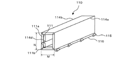
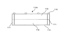
上記構成の内部ユニット120は、周囲をスリーブ110で覆われており、スリーブ110と2つの端面具130で防水可能に保護されている。スリーブ110の斜視図を図3に示す。スリーブ110の左右両端には、高さN、幅Mの開口部が形成され、ここに端面具130を嵌合させるための端面嵌合部111が備えられている。端面嵌合部111に端面具130を嵌合させて端面を封止することで、内蔵されている内部ユニット120を保護している。
The
光ファイバケーブルのスリーブ110への導入方向と垂直な方向をスリーブ110の縦方向としたとき、スリーブ110の縦寸法は端面具130の外周を取り巻く長さとなっており、横寸法は、2つの端面具130間の距離である連結棒121の軸方向長さにほぼ等しくなっている。スリーブ110の両端に設けられた端面嵌合部111は、外側リブ111aと内側リブ111bとで構成されており、外側リブ111aと内側リブ111bとの間に端面具130が設置される構成になっている。外側リブ111aと内側リブ111bの高さは、防水性を確保するために、端面具130を嵌合したときに隙間なく密閉できる高さとしている。端面嵌合部111はまた、端面具130の位置決めを行う役目も果たしている。
When the direction perpendicular to the direction in which the optical fiber cable is introduced into the
スリーブ110を展開して平板上にしたときの展開図を図4に示す。本実施形態のスリーブ110は、横寸法が連結棒121の軸方向長さにほぼ等しく、縦寸法が端面具130の短辺の長さMに等しいスリーブエレメント112と、同じく縦寸法が端面具130の長辺の長さNに等しいスリーブエレメント113とを連結して構成されている。本実施形態のクロージャ100では、2枚のスリーブエレメント112と2枚のスリーブエレメント113とを交互に連結したスリーブを基本スリーブ110aとしており、内部ユニット120を1つだけ収納する場合には基本スリーブ110aのみを用いてスリーブ110を構成している。
FIG. 4 shows a developed view when the
2枚のスリーブエレメント112と2枚のスリーブエレメント113とは、それぞれヒンジ114を用いて連結されている。ヒンジ114a、114b、及び114cでそれぞれ直角に折り曲げることにより、図3に示すような直方体のスリーブ110が形成される。なお、基本スリーブ110aには、さらにヒンジ114dが形成されているが、これは後述するように基本スリーブ110aを拡張して用いる場合に必要となるものである。
The two
また、スリーブ110aの縦方向の両端辺を閉じるために、1方の端辺には連結具115が設けられ、他方の端辺には連結具115と連結させるための連結受片116が設けられている。図4のように展開されたスリーブ110は、図5に示すように、ヒンジ114で順次直角に曲げられて直方体を形成し、最後に連結具115を連結受片116に連結して図3の状態にされる。
Further, in order to close both ends in the longitudinal direction of the
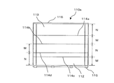
次に、本実施形態の光ファイバケーブル用クロージャ100を、2つの内部ユニット120が収納できるように拡張したときの実施例を図6に示す。図6(a)は、2つの内部ユニット120を収納するよう拡張された本実施形態のクロージャ101を示す上断面図であり、(b)は横断面図、(c)は2つの端面具130からなる端面を示す図である。
Next, FIG. 6 shows an example when the optical
本実施例では、既設の内部ユニット120に増設の内部ユニット120aが追加されており、2つの内部ユニット120、120aが2つの連結部材126で連結されている。連結棒121には、各々の連結部材126を取付けるためのボルト取付け用ネジ孔が設けられ、連結部材126にも相当する位置にボルト取付け用ネジ孔が空けられており、各ネジ孔にボルトを通して連結している。ここでは、連結部材126を連結棒121に取付けるようにしているが、端面具130や光ファイバトレイ収納具123等に取付けるようにしてもよい。
In this embodiment, an additional
2つの内部ユニット120、120aを収納するよう拡張されたクロージャ101では、2つの内部ユニット120、120aを一体に覆うようスリーブも拡張する必要がある。本実施形態では、スリーブ140として基本スリーブ110aに加えて増設スリーブ110bを連結して用いるようにしている。増設スリーブ110bの1実施例を図7に示す。図7に示す増設スリーブ110bは、横寸法が連結棒121の軸方向長さにほぼ等しく、縦寸法が端面具130の短辺の長さMに等しい2つのスリーブエレメント112を連結して構成したものであり、平板状に一体化してもよいし、ヒンジで屈曲可能に連結してもよい。また、増設スリーブ110bにも、基本スリーブ110aと同様の端面嵌合部111と、連結具115及び連結受片116が設けられている。
In the closure 101 expanded to accommodate the two
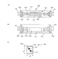
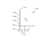
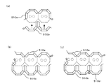
2つの内部ユニット120を収納できるよう、基本スリーブ110aと増設スリーブ110bを用いて形成されたスリーブ140を図1に示す。図1(a)は、スリーブ140の斜視図であり、(b)は基本スリーブ110aと増設スリーブ110bとの連結を説明するための断面図である。スリーブ140は、左右両端に高さN,幅2Mの開口部が形成されており、これは図6(c)に示す2つの端面具130を嵌合可能な大きさとなっている。
FIG. 1 shows a
スリーブ140を形成するために、基本スリーブ110aをヒンジ114b、114cで折り曲げる代わりに、ヒンジ114dで折り曲げるようにしている。図1(b)に示すように、ヒンジ114aとヒンジ114dで折り曲げられてコの字状に形成された基本スリーブ110aと増設スリーブ110bとを連結することにより、図1(a)に示すような直方体のスリーブ140を形成している。図6(c)において、2つの端面具130は密着されて防水可能な端面を形成しており、この端面を基本スリーブ110a及び増設スリーブ110bに備えられた端面嵌合部111で嵌合して密閉することで、内部に収納された2つの内部ユニット120、120aを防水可能に保護するクロージャ101を形成している。
In order to form the
上記の通り、本実施形態によれば、内部ユニット120を1つだけ収納する場合は、基本スリーブ110aだけで形成されたスリーブ110を備えたクロージャ100を用いることができ、増設の内部ユニット120aが追加されて2つの内部ユニット120、120aを収納する場合には、基本スリーブ110aと増設スリーブ110bとを連結して構成成されたスリーブ140を用いてクロージャ101を構成することができる。
As described above, according to the present embodiment, when only one
あるいは、スリーブ140を用いた2つの内部ユニット120、120aを収納したクロージャ101から1つの内部ユニット120aを撤去した場合には、基本スリーブ110aを再利用し、これだけでスリーブ110を形成してクロージャ100を形成することも可能である。このように、本実施形態の光ファイバケーブル用クロージャ100及び101では、収納する内部ユニットの増設・撤去に応じて、基本スリーブ110a及び増設スリーブ110bを無駄なく再利用して必要な大きさのスリーブを構成することが可能となる。
Alternatively, when one
上記の実施例では、内部ユニット120を2つまで収納するクロージャについて説明したが、内部ユニット120をさらに増設して3つ以上収納するクロージャを形成することも可能である。この場合、内部ユニット120を増減する毎に増設スリーブ110bを増減してスリーブを構成する。また、上記の実施例では、増設スリーブとして縦寸法が端面具130の短辺の長さMに等しい2つのスリーブエレメント112を連結して構成したものを用いたが、クロージャの形状に応じて縦寸法が端面具130の長辺の長さNに等しい2つのスリーブエレメント112を連結して構成したものを用いてもよい。また、収納する内部ユニットの個数に応じて、基本スリーブ110a及び増設スリーブ110bには、所定の位置にヒンジ114を事前に形成しておく。なお、上記実施例において、端面具130の短辺の長さMと長辺の長さNが等しい場合には、114d等の追加のヒンジは不要となる。
In the above-described embodiment, the closure for storing up to two
本発明の光ファイバケーブル用クロージャの第二の実施形態を、図8に示す実施例を用いて以下に説明する。図8は、本実施形態のクロージャで用いられるスリーブ210と端面具230のみを示している。本実施形態のスリーブ210は、端面具230の短辺の長さをPとし長辺の長さをQとしたとき、縦寸法がPのスリーブエレメント212と、縦寸法がQのスリーブエレメント213を所定の連結具(図示せず)で連結して構成されている。すなわち、本実施形態では、2以上のスリーブエレメント212、213が事前にヒンジで連結されておらず、それぞれのスリーブエレメント212、213を連結具で連結してスリーブを構成するようにしたものである。
A second embodiment of the optical fiber cable closure of the present invention will be described below using the example shown in FIG. FIG. 8 shows only the
図8に示す実施例では、クロージャに収納する内部ユニットが1つの場合を示したが、2以上の内部ユニットを収納するクロージャを構成する場合も同様に、収納する内部ユニットの個数に対応したスリーブエレメントを選択し、これを所定の連結具で連結してスリーブを構成することができる。あるいは、図8に示すスリーブエレメント212、213を連結具でさらに連結して構成することも可能である。
In the embodiment shown in FIG. 8, the case where there is one internal unit stored in the closure is shown. However, in the case of configuring a closure that stores two or more internal units, similarly, the sleeve corresponding to the number of internal units stored. A sleeve can be configured by selecting elements and connecting them with a predetermined connector. Alternatively, the
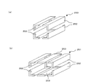
本発明の光ファイバケーブル用クロージャの第三の実施形態を、図9に示す実施例を用いて以下に説明する。図9では、本実施形態のクロージャで用いられるスリーブのみを示しており、(a)は1つの内部ユニットを収納するときに用いられる基本スリーブ250の構成を示す斜視図であり、(b)は内部ユニットを1つ増設したときのスリーブ251の構成を示す斜視図である。
A third embodiment of the optical fiber cable closure of the present invention will be described below using the example shown in FIG. In FIG. 9, only the sleeve used in the closure of the present embodiment is shown, (a) is a perspective view showing the configuration of a
図9(a)に示す基本スリーブ250は、角部を有するスリーブエレメント252を4つ用い、それぞれを所定の連結具(図示せず)で連結して構成されている。本実施形態で用いる基本スリーブ250は、1種類のスリーブエレメント252のみで構成されるようにしたものである。また図9(b)に示すスリーブ251は、基本スリーブ250に2つの増設スリーブ253を連結して構成されている。
The
本実施形態で用いる増設スリーブ253は、1つの平面状のスリーブエレメントで構成されており、内部ユニットを1つ追加した場合は、2枚の増設ユニット253を追加してスリーブを構成する。増設ユニット253は、2つのスリーブエレメント252の間に配置されて所定の連結具(図示せず)で連結される。上記の通り本実施形態のスリーブは、スリーブエレメント252と増設ユニット253の2種類のスリーブエレメントのみで構成することができる。また、角部を有するスリーブエレメント252を用いることで折り曲げ可能な可動部を形成する必要がなくなり、ヒンジ等が不要な低コストのスリーブを提供することが可能となる。
The
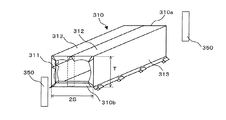
本発明の光ファイバケーブル用クロージャの第四の実施形態を、図面を用いて以下に説明する。図10は、本実施形態のクロージャの一実施例を示す図であり、2つの内部ユニット320、320aを収納するクロージャ300を示している。図10(a)はクロージャ300の上断面図であり、(b)は横断面図、(c)は端面具330を示している。図10(c)に示すように、本実施形態のクロージャ300は、略楕円形状の端面具330を備えている。また、クロージャ300に用いられるスリーブ310の斜視図を図11に示す。
A fourth embodiment of the optical fiber cable closure of the present invention will be described below with reference to the drawings. FIG. 10 is a diagram showing an example of the closure according to the present embodiment, and shows a
端面具330の短軸の長さをSとし、長軸の長さをTとしたとき、第一の実施形態と同様に、縦寸法がSとTの2種類のスリーブエレメント312,313を用いて、ヒンジでそれぞれ2つずつ交互に連結した基本スリーブ310aと、2つのスリーブエレメント312を一体化した増設スリーブ310bを形成することができる。そして、内部ユニット320を1つだけ収納する場合は、基本スリーブ310aだけでスリーブを形成し、2つの内部ユニット320、320aを収納するクロージャ300では、基本スリーブ310aと増設スリーブ310bとを連結してスリーブ310を構成することが可能となる。
When the length of the short axis of the
なお、本実施形態に用いられるスリーブエレメント312,313には、端面具330の形状に合わせて形成された円弧状のリブからなる端面嵌合部311が備えられている。これにより、端面嵌合部311に端面具330を隙間なく嵌合させることができる。しかしながら、端面嵌合部311を上記のように形成しても、端面具330が略楕円形状の場合には、2つの端面具330が接する位置に隙間が形成されてしまう。そこで、本実施形態では、2つの端面具330の接合部を密閉するために端面止水部材350を用いるようにしている。端面止水部材350を用いることにより、収納された内部ユニット320を防水可能に保護できるクロージャ300を構成することが可能となる。
The
本発明の光ファイバケーブル用クロージャの第五の実施形態を、図面を用いて以下に説明する。本実施形態では、図12(a)に示すようなスリーブ410を用いている。スリーブ410は、所定幅のスリーブエレメント413をヒンジ414で連結して形成されている。図12に示す実施例では、内部ユニットを1つだけ収納する場合に用いられる基本スリーブ410aを、複数のスリーブエレメント413で構成するようにしている。
A fifth embodiment of the optical fiber cable closure of the present invention will be described below with reference to the drawings. In the present embodiment, a
基本スリーブ410aは、複数個のスリーブエレメント413で端面具430の長辺と短辺に一致させて嵌合できるように、スリーブエレメント413の幅を決定しておく必要がある。このように形成されたスリーブエレメント413からなる基本スリーブ410aを用いて、内部ユニットを1つだけ収納する場合のスリーブ410を形成する方法を図12(b)に示している。基本スリーブ410aは、端面具430の角で折り曲げることが可能であり、端面具430の全周を取り巻いた後に、連結具415でスリーブ410を封止することができる。
The width of the
本実施形態において、内部ユニットを2以上収納する場合のスリーブの実施例を図13に示す。図13(a)は2つの内部ユニットを収納する場合の実施例であり、(b)と(c)は3つの内部ユニットを収納する実施例を示している。いずれの実施例においても、基本スリーブ410aと増設スリーブ410b、410c、410dを用いてスリーブを構成している。なお、図13(b)では、3つの内部ユニットに適合させた増設スリーブ410cを用いており、図13(c)では2つの内部ユニットに適合させた増設スリーブ410bとさらに別の増設スリーブ410dを組み合わせて用いている。
FIG. 13 shows an example of a sleeve when two or more internal units are accommodated in this embodiment. FIG. 13A shows an embodiment in which two internal units are accommodated, and FIGS. 13B and 13C show an embodiment in which three internal units are accommodated. In any embodiment, the
本実施形態の基本スリーブ410aでは、スリーブエレメント413を連結して構成されていることから、収納する内部ユニットの個数にかかわらず、複数の端面具430で構成された端面の角で折り曲げることが可能となる。そして、スリーブの不足部分を第一の実施形態と同様の増設スリーブで補うようにすることができる。(上記の段落に移動)
Since the
本実施形態のさらに別の実施例を図14に示す内部ユニットを2つ収納するスリーブを形成する方法を図14(a)、内部ユニットを3つ収納するスリーブを形成する方法を図14(b)に示している。同図に示す実施例では、増設スリーブ410e、410fもスリーブエレメント413を連結して構成している。増設スリーブ410e、410fをスリーブエレメント413を連結して構成することにより、収納する内部ユニットの個数によらずこれを用いることが可能となる。
FIG. 14 (a) shows a method of forming a sleeve that houses two internal units shown in FIG. 14, and FIG. 14 (b) shows a method of forming a sleeve that houses three internal units. ). In the embodiment shown in the figure, the
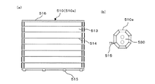
本発明の光ファイバケーブル用クロージャの第六の実施形態を、図15の実施例を用いて以下に説明する。本実施形態のクロージャは、多角形の形状を有している端面具530で構成されているのを特徴としている。また、本実施形態のクロージャを構成するスリーブとして、第四の実施形態と同様に、所定幅のスリーブエレメント513をヒンジ514で連結して構成されたスリーブ510を用いている。図15(a)に、スリーブ510の展開図を示す。
A sixth embodiment of the optical fiber cable closure of the present invention will be described below using the example of FIG. The closure of the present embodiment is characterized by being composed of an
基本スリーブ510aを1つの端面具530に取り付けた状態を図15(b)に示す。本実施例では、端面具530の形状を八角形としており、複数のスリーブエレメント513で形成されたスリーブ510を基本スリーブ510aとしている。スリーブエレメント513の幅は、端面具530の1辺の長さに等しくなるように形成されており、基本スリーブ510aを構成する各スリーブエレメント513の端面嵌合部が端面具530の各辺と嵌合されている。基本スリーブ510aを端面具530に巻付けた後、連結具515で基本スリーブ510aの両端を連結している。
A state where the
本実施形態において、複数の内部ユニットを収納する場合のスリーブの実施例を図16に示す。同図において、(a)は2つの内部ユニットを収納する場合の実施例であり、(b)と(c)は3つの内部ユニットを収納する実施例を示している。いずれの実施例においても、基本スリーブ510aと増設スリーブ510b、510c、510dを用いてスリーブを構成している。
FIG. 16 shows an example of a sleeve when a plurality of internal units are accommodated in this embodiment. In the figure, (a) shows an embodiment in which two internal units are accommodated, and (b) and (c) show an embodiment in which three internal units are accommodated. In any of the embodiments, the
本実施形態の基本スリーブ510aでは、スリーブエレメント513を連結して構成されていることから、収納する内部ユニットの個数にかかわらず、複数の端面具530で構成された端面の角で折り曲げることが可能となる。また、増設スリーブ510b、510c、510dも、基本スリーブ510aと同様にスリーブエレメント513を連結して構成されている。図16(b)では、3つの内部ユニットに適合させた個数のスリーブエレメント513を連結した増設スリーブ510cを用いており、図16(c)では2つの内部ユニットに適合させた増設スリーブ510bとさらに別の増設スリーブ510dを組み合わせて用いている。
Since the
なお、本実施形態の端面具530の形状は、長方形または正方形ではなく、楕円形に近い八角形を有しているが、図16に示すように、端面具530同士の接触部にも2つのスリーブ片513を背中合わせにして配設することができる。これにより、防水性をさらに高めることが可能となる。
In addition, although the shape of the
本発明の光ファイバケーブル用クロージャでは、スリーブを連結するために連結具を用いていた。連結具として種々の形状のものを用いることができ、例えば図17に示すようなものが利用可能である。図17(a)及び(b)は、連結具がファスナー式のものであり、図17(c)はラッチ式のものである。 In the optical fiber cable closure of the present invention, a connector is used to connect the sleeves. A connector having various shapes can be used. For example, a connector as shown in FIG. 17 can be used. 17 (a) and 17 (b), the coupling tool is a fastener type, and FIG. 17 (c) is a latch type.
図17(a)に示す連結具610は、連結受片611の端部から矢印A1のように挿入されて、スリーブエレメント601と602を連結している。また図16(b)では、連結具620を連結受片621の一部が欠落した位置622に移動させたときに、連結具620による連結から解除できるように形成されたものである。さらに、図16(c)に示すラッチ式では、連結具のラッチ630を連結受片631に嵌合させてスリーブ601と602を連結する。あるいは、矢印A2のようにラッチ630を引き上げて連結受片631から解除し、スリーブ601と602を分離する。
A
上記説明の通り、本発明の光ファイバケーブル用クロージャでは、既設容量を超えて光ファイバケーブルないしは光ファイバトレイ枚数を増大させる場合に、既設クロージャに使用されているスリーブを大容量クロージャのスリーブの一部に組み込める構造としており、スリーブを再利用することが可能となっている。これにより、既設クロージャのスリーブを廃棄する必要はなくなり、廃棄物を抑制し資源を有効利用できるといった優れた効果が得られる。 As described above, in the optical fiber cable closure of the present invention, when the number of optical fiber cables or optical fiber trays is increased beyond the existing capacity, the sleeve used for the existing closure is one of the sleeves of the large capacity closure. The sleeve can be incorporated, and the sleeve can be reused. Thereby, it is not necessary to discard the sleeve of the existing closure, and an excellent effect that the waste can be suppressed and resources can be effectively used is obtained.
また、複数個の内部ユニットを収納する大容量のクロージャから一部の内部ユニットを撤去して小型化する場合には、例えば増設用スリーブを取り外すことで小型のスリーブを容易に形成することが可能である。取り外された増設用スリーブは、廃棄することなくそのまま別途再利用することが可能である。 In addition, when some internal units are removed from a large-capacity closure that houses multiple internal units for downsizing, for example, a small sleeve can be easily formed by removing an expansion sleeve. It is. The removed expansion sleeve can be reused as it is without being discarded.
一般に、スリーブはプラスチック成形品として製造されているため、スリーブが大型化されると、その製造に用いられる成形金型や成形機等も大型化され、製造コストが上昇してしまう原因となっている。これに対し本発明のクロージャでは、スリーブエレメントを連結してスリーブを大型化することが可能なことから、低コストで製造可能な小型のスリーブエレメントを用い、収納する内部ユニットの個数に応じてスリーブエレメントを組み合わせてスリーブを構成できるといった優れた効果が得られる。 In general, since a sleeve is manufactured as a plastic molded product, when the sleeve is enlarged, a molding die, a molding machine, and the like used for the manufacture are also enlarged, which increases the manufacturing cost. Yes. On the other hand, in the closure of the present invention, since it is possible to increase the size of the sleeve by connecting the sleeve elements, a small sleeve element that can be manufactured at low cost is used, and the sleeve is selected according to the number of internal units to be accommodated. An excellent effect that a sleeve can be configured by combining elements is obtained.
なお、本実施の形態における記述は、本発明に係る光ファイバケーブル用クロージャの一例を示すものであり、これに限定されるものではない。本実施の形態における光ファイバケーブル用クロージャの細部構成及び詳細な動作等に関しては、本発明の趣旨を逸脱しない範囲で適宜変更可能である。 In addition, the description in this Embodiment shows an example of the closure for optical fiber cables which concerns on this invention, and is not limited to this. The detailed configuration and detailed operation of the optical fiber cable closure in the present embodiment can be changed as appropriate without departing from the spirit of the present invention.
10 光ファイバケーブル 100、101、300 クロージャ
110、140、210、250、251、310、410 スリーブ
110a、410a、510a 基本スリーブ
110b、410b、510b 増設スリーブ
111 端面嵌合部
112、113、212、213、252、253、412、512 スリーブエレメント
114、132、414、514 ヒンジ
115、415、515 連結具
116、416、516 連結受片
120、120a 内部ユニット
121 連結棒
122 光ファイバトレイ
123 光ファイバトレイ収納具
124 ケーブル外被把持具
125 テンションメンバ把持具
126 連結部材
130、230、330、430、530 端面具
131 ケーブル導入孔
133 分割線
350 端面止水部材
413、513 スリーブ片
601、602 スリーブエレメント
610、620 連結具
611、621、631 連結受片
630 ラッチ
10
Claims (7)
前記光ファイバケーブルの前記スリーブへの導入方向に垂直な方向を前記スリーブの縦方向としたとき、2以上のスリーブエレメントが前記スリーブの縦方向に屈曲可能に連結されて前記スリーブが構成されており、
前記内部ユニットが1つだけ収納されているときの前記スリーブを基本スリーブとしたとき、
前記内部ユニットがさらに増設された場合は、前記スリーブエレメントの屈曲可能な連結部分を利用して前記基本スリーブを拡張形状に変え、この拡張形状の基本スリーブに対して1または2以上の前記スリーブエレメントから構成される増設スリーブを連結して前記基本スリーブを閉じることにより、拡張された前記スリーブが構成可能とされていることを特徴とする光ファイバケーブル用クロージャ。 An optical fiber cable closure comprising an internal unit having at least an end face tool having an introduction hole for introducing an optical fiber cable from the outside, and a sleeve covering the internal unit,
When the direction perpendicular to the introduction direction of the optical fiber cable into the sleeve is defined as the longitudinal direction of the sleeve, two or more sleeve elements are connected to be able to bend in the longitudinal direction of the sleeve to constitute the sleeve. ,
When the sleeve when only one internal unit is accommodated is a basic sleeve,
When the internal unit is further expanded , the basic sleeve is changed to an expanded shape by using a bendable connecting portion of the sleeve element , and one or more sleeve elements are added to the expanded basic sleeve. An optical fiber cable closure characterized in that the expanded sleeve can be constructed by connecting an additional sleeve comprising: and closing the basic sleeve .
前記基本スリーブは、前記縦寸法がMとNの前記スリーブエレメントを2枚ずつ交互にそれぞれ屈曲可能に連結して構成されており、
前記増設スリーブは、2枚の前記縦寸法がMまたはNの前記スリーブエレメントを屈曲可能に連結して構成されていることを特徴とする請求項1または2に記載の光ファイバケーブル用クロージャ。 When the length of the short side or short axis of the end face tool is M and the length of the long side or long axis is N,
The basic sleeve is configured by connecting the sleeve elements having the longitudinal dimensions of M and N alternately to each other so that they can be bent two by two,
3. The optical fiber cable closure according to claim 1, wherein the additional sleeve is configured by connecting the two sleeve elements having a longitudinal dimension of M or N so as to be bendable. 4.
前記内部ユニットを2以上収納したときに形成される前記端面具間が前記端面止水部材で防水可能に封止されていることを特徴とする請求項1から請求項4のいずれか1項に記載の光ファイバケーブル用クロージャ。 An end face water stop member,
The space between the end face tools formed when two or more of the internal units are stored is sealed with the end face water-stopping member so as to be waterproof. An optical fiber cable closure as described.
前記光ファイバケーブルの前記スリーブへの導入方向に垂直な方向を前記スリーブの縦方向としたとき、2以上のスリーブエレメントが前記スリーブの縦方向に屈曲可能に連結されて前記スリーブが構成されており、
前記内部ユニットが1つだけ収納されているときの前記スリーブを基本スリーブとしたとき、
前記内部ユニットがさらに増設された場合は、前記スリーブエレメントの屈曲可能な連結部分を利用して前記基本スリーブを拡張形状に変え、この拡張形状の基本スリーブに対して1または2以上の前記スリーブエレメントから構成される増設スリーブを連結して前記基本スリーブを閉じることにより、拡張された前記スリーブを構成し、
前記内部ユニットの増設または撤去に合わせて前記増設スリーブを追加または削減して前記スリーブを構成することを特徴とする光ファイバケーブル用クロージャの拡張・縮小方法。 An expansion / reduction method for an optical fiber cable closure comprising at least an internal unit having an end surface tool having an introduction hole for introducing an optical fiber cable from the outside, and a sleeve covering the internal unit,
When the direction perpendicular to the introduction direction of the optical fiber cable into the sleeve is defined as the longitudinal direction of the sleeve, two or more sleeve elements are connected to be able to bend in the longitudinal direction of the sleeve to constitute the sleeve. ,
When the sleeve when only one internal unit is accommodated is a basic sleeve,
When the internal unit is further expanded , the basic sleeve is changed to an expanded shape by using a bendable connecting portion of the sleeve element , and one or more sleeve elements are added to the expanded basic sleeve. The expanded sleeve is connected to form the expanded sleeve by closing the basic sleeve .
A method for expanding / reducing a closure for an optical fiber cable, wherein the sleeve is configured by adding or reducing the expansion sleeve in accordance with expansion or removal of the internal unit.
Priority Applications (1)
| Application Number | Priority Date | Filing Date | Title |
|---|---|---|---|
| JP2006304067A JP4875463B2 (en) | 2006-11-09 | 2006-11-09 | Optical fiber cable closure and optical fiber cable closure expansion / contraction method |
Applications Claiming Priority (1)
| Application Number | Priority Date | Filing Date | Title |
|---|---|---|---|
| JP2006304067A JP4875463B2 (en) | 2006-11-09 | 2006-11-09 | Optical fiber cable closure and optical fiber cable closure expansion / contraction method |
Publications (2)
| Publication Number | Publication Date |
|---|---|
| JP2008122521A JP2008122521A (en) | 2008-05-29 |
| JP4875463B2 true JP4875463B2 (en) | 2012-02-15 |
Family
ID=39507358
Family Applications (1)
| Application Number | Title | Priority Date | Filing Date |
|---|---|---|---|
| JP2006304067A Active JP4875463B2 (en) | 2006-11-09 | 2006-11-09 | Optical fiber cable closure and optical fiber cable closure expansion / contraction method |
Country Status (1)
| Country | Link |
|---|---|
| JP (1) | JP4875463B2 (en) |
Families Citing this family (1)
| Publication number | Priority date | Publication date | Assignee | Title |
|---|---|---|---|---|
| JP2010243714A (en) * | 2009-04-03 | 2010-10-28 | Furukawa Electric Co Ltd:The | Closure for optical cable |
Family Cites Families (2)
| Publication number | Priority date | Publication date | Assignee | Title |
|---|---|---|---|---|
| JPH07245862A (en) * | 1994-03-01 | 1995-09-19 | Furukawa Electric Co Ltd:The | Cable connection box and method for extend cable by using the same |
| JP4073394B2 (en) * | 2003-12-05 | 2008-04-09 | 株式会社昭電 | closure |
-
2006
- 2006-11-09 JP JP2006304067A patent/JP4875463B2/en active Active
Also Published As
| Publication number | Publication date |
|---|---|
| JP2008122521A (en) | 2008-05-29 |
Similar Documents
| Publication | Publication Date | Title |
|---|---|---|
| JP2008025775A (en) | Collapsible cable protection guiding device | |
| BRPI0617063A2 (en) | housing for electrical conductor and connector assembly | |
| JP2012016204A (en) | Electrical junction box | |
| KR100659017B1 (en) | A waterproofing electric wire official for buildings | |
| JP4875463B2 (en) | Optical fiber cable closure and optical fiber cable closure expansion / contraction method | |
| JP2008221357A (en) | Multi-joint robot | |
| JP5265995B2 (en) | Wiring / pipe protection material | |
| KR100889841B1 (en) | The cable unit of arm robot | |
| JP4717599B2 (en) | Flexible cable duct | |
| JP2009198701A (en) | Optical fiber cable | |
| JP7028677B2 (en) | Protective equipment and manufacturing method of protective equipment | |
| JP4504855B2 (en) | Corrugated tube device, corrugated tube holder, and corrugated tube | |
| JP2008017544A (en) | Telescopical joint box | |
| KR20150002207U (en) | Curved piece and cover assembly coupled with the same | |
| JP5654097B2 (en) | Optical fiber storage case | |
| JP2010220361A (en) | Tube shape maintaining member and support structure of corrugated tube using the same | |
| JP2007252060A (en) | Harness armoring member | |
| JP2015162955A (en) | Corrugate tube and electric wire module | |
| JP2009098164A (en) | Optical closure | |
| JP5150322B2 (en) | Telescopic joint box | |
| JPH0943437A (en) | Cable wiring method and cable wiring means | |
| JP2005065399A (en) | Protector and method of manufacturing wire harness | |
| JP6307295B2 (en) | Wire harness fixing structure | |
| JP2007304163A (en) | End seal member of closure for cable connecting part and closure for cable connecting part | |
| JP2004311614A (en) | Fixed structure of electric supply cable protection member |
Legal Events
| Date | Code | Title | Description |
|---|---|---|---|
| A621 | Written request for application examination |
Free format text: JAPANESE INTERMEDIATE CODE: A621 Effective date: 20081204 |
|
| A977 | Report on retrieval |
Free format text: JAPANESE INTERMEDIATE CODE: A971007 Effective date: 20100708 |
|
| A131 | Notification of reasons for refusal |
Free format text: JAPANESE INTERMEDIATE CODE: A131 Effective date: 20110902 |
|
| A521 | Request for written amendment filed |
Free format text: JAPANESE INTERMEDIATE CODE: A523 Effective date: 20111028 |
|
| TRDD | Decision of grant or rejection written | ||
| A01 | Written decision to grant a patent or to grant a registration (utility model) |
Free format text: JAPANESE INTERMEDIATE CODE: A01 Effective date: 20111121 |
|
| A01 | Written decision to grant a patent or to grant a registration (utility model) |
Free format text: JAPANESE INTERMEDIATE CODE: A01 |
|
| A61 | First payment of annual fees (during grant procedure) |
Free format text: JAPANESE INTERMEDIATE CODE: A61 Effective date: 20111125 |
|
| FPAY | Renewal fee payment (event date is renewal date of database) |
Free format text: PAYMENT UNTIL: 20141202 Year of fee payment: 3 |
|
| R151 | Written notification of patent or utility model registration |
Ref document number: 4875463 Country of ref document: JP Free format text: JAPANESE INTERMEDIATE CODE: R151 |
|
| FPAY | Renewal fee payment (event date is renewal date of database) |
Free format text: PAYMENT UNTIL: 20141202 Year of fee payment: 3 |
|
| R250 | Receipt of annual fees |
Free format text: JAPANESE INTERMEDIATE CODE: R250 |
|
| R250 | Receipt of annual fees |
Free format text: JAPANESE INTERMEDIATE CODE: R250 |
|
| S533 | Written request for registration of change of name |
Free format text: JAPANESE INTERMEDIATE CODE: R313533 |
|
| R350 | Written notification of registration of transfer |
Free format text: JAPANESE INTERMEDIATE CODE: R350 |
|
| R250 | Receipt of annual fees |
Free format text: JAPANESE INTERMEDIATE CODE: R250 |
|
| R250 | Receipt of annual fees |
Free format text: JAPANESE INTERMEDIATE CODE: R250 |
|
| R250 | Receipt of annual fees |
Free format text: JAPANESE INTERMEDIATE CODE: R250 |
|
| R250 | Receipt of annual fees |
Free format text: JAPANESE INTERMEDIATE CODE: R250 |
|
| R250 | Receipt of annual fees |
Free format text: JAPANESE INTERMEDIATE CODE: R250 |
|
| S531 | Written request for registration of change of domicile |
Free format text: JAPANESE INTERMEDIATE CODE: R313531 |
|
| R350 | Written notification of registration of transfer |
Free format text: JAPANESE INTERMEDIATE CODE: R350 |
|
| R250 | Receipt of annual fees |
Free format text: JAPANESE INTERMEDIATE CODE: R250 |
|
| R250 | Receipt of annual fees |
Free format text: JAPANESE INTERMEDIATE CODE: R250 |
|
| R250 | Receipt of annual fees |
Free format text: JAPANESE INTERMEDIATE CODE: R250 |