JP4875246B2 - Solid oxide fuel cell system - Google Patents
Solid oxide fuel cell system Download PDFInfo
- Publication number
- JP4875246B2 JP4875246B2 JP2001103867A JP2001103867A JP4875246B2 JP 4875246 B2 JP4875246 B2 JP 4875246B2 JP 2001103867 A JP2001103867 A JP 2001103867A JP 2001103867 A JP2001103867 A JP 2001103867A JP 4875246 B2 JP4875246 B2 JP 4875246B2
- Authority
- JP
- Japan
- Prior art keywords
- gas
- fuel cell
- solid oxide
- supply
- oxide fuel
- Prior art date
- Legal status (The legal status is an assumption and is not a legal conclusion. Google has not performed a legal analysis and makes no representation as to the accuracy of the status listed.)
- Expired - Fee Related
Links
Images


Classifications
-
- Y—GENERAL TAGGING OF NEW TECHNOLOGICAL DEVELOPMENTS; GENERAL TAGGING OF CROSS-SECTIONAL TECHNOLOGIES SPANNING OVER SEVERAL SECTIONS OF THE IPC; TECHNICAL SUBJECTS COVERED BY FORMER USPC CROSS-REFERENCE ART COLLECTIONS [XRACs] AND DIGESTS
- Y02—TECHNOLOGIES OR APPLICATIONS FOR MITIGATION OR ADAPTATION AGAINST CLIMATE CHANGE
- Y02E—REDUCTION OF GREENHOUSE GAS [GHG] EMISSIONS, RELATED TO ENERGY GENERATION, TRANSMISSION OR DISTRIBUTION
- Y02E60/00—Enabling technologies; Technologies with a potential or indirect contribution to GHG emissions mitigation
- Y02E60/30—Hydrogen technology
- Y02E60/50—Fuel cells
Landscapes
- Fuel Cell (AREA)
Description
【0001】
【発明の属する技術分野】
本発明は、固体電解質型燃料電池システムに関する。
【0002】
【従来の技術】
高温固体電解質型燃料電池の構造の一例が特開平9−129256で知られている。高温固体電解質型燃料電池の動作温度は800℃から1000℃を想定している。この引例では、セルチューブ(燃料電池モジュール)は、上部管板と下部管板に固定されて、下部管板の下方に延びている。水分を含む燃料ガスは、天板と上部管板の間に供給されている。下部管板の下には酸化剤ガスが充満している。燃料ガスはセルチューブに供給され発電に使用される。発電後の排燃料ガスは、セルチューブから上部管板と下部管板との間に排出され、更に外部に排出される。
【0003】
高温固体電解質型燃料電池では、メタンガス等の炭化水素を含有するガス(都市ガス)を供給ガスとして使用することが検討されている。メタンガスを供給ガスとして使用する場合には、
CH4 + H2O → CO + 3H2 −Q (1)
で表される反応式に基づいて、メタンガスを水素ガスを含むガスに改質することが望ましい。なお、この反応は吸熱反応である。生成された水素ガスが燃料ガスとして酸化剤ガスとともに発電に使用される。発電の際の反応は
2H2 + O2 → 2H2O +Q
2CO + O2 → 2CO2 +Q (2)
である。この反応は、発熱反応である。
【0004】
この改質では、上記の反応式に示されるように、水分が必要である。水分が関与してメタンガスが一酸化炭素と水素に分解されている。従って、改質器を通った燃料ガスは、メタン、水分、一酸化炭素、二酸化炭素、水素を含むことになる。これらのガス成分のうち水素ガスだけ抽出して燃料電池に導入することは実際的ではないので、水分を含む燃料ガスが燃料電池に供給されることになる。
【0005】
水分を如何に供給するかが問題である。一般的には、ボイラにより蒸気という形で水分が補給されている。しかしながら、ボイラ等の付帯設備を設けることはシステムのコストを押し上げることになる。従って、ボイラの使用はできるだけさけるべきである。その場合、水分を如何に補給するかが問題となる。
【0006】
所定の条件における定格運転では、上記反応式(2)に従って水分は生成される。この水分を改質に使用することができる。しかしながら、発電当初は、その水分が無いのでボイラを使用せざるを得ない。そこで、ボイラを使用する必要のない固体電解質型燃料電池システムが要望されている。
【0007】
また、システムの停止時に、いきなり発電を停止すると、メタンガスがそのままセルチューブ入り、
CH4 → C+2H2
の反応式に従って熱分解されて炭素が付着することになる。この炭素はセルチューブの性能を低下させる。そのため、停止時にそれまでの燃料ガスをパージしなければならないが、余分な構成のシステムへの追加はさけるべきである。
【0008】
また、固体電解質型燃料電池から排出される排燃料ガスには可燃成分が含まれており、排燃料ガスの一部は循環されるが、残りは排出されている。これはエネルギー的には、効率がよくない。燃料の使用効率を高めた固体電解質型燃料電池システムが望まれている。
【0009】
【発明が解決しようとする課題】
従って、本発明の目的は、安定に電力を取り出すことができる固体電解質型燃料電池システムを提供することである。
【0010】
本発明の他の目的は、起動時に水蒸気を供給する必要が無く、ボイラーなどの付帯設備を設ける必要のない固体電解質型燃料電池システムを提供することである。
【0011】
本発明の他の目的は、起動時及び停止時に炭素による燃料電池モジュールの汚染を防止することができる固体電解質型燃料電池システムを提供することである。
【0012】
本発明の他の目的は、ガスタービンを用いて燃料ガスを有効に利用することにより発電効率を高めた固体電解質型燃料電池システムを提供することである。
【0013】
【課題を解決するための手段】
以下に、本発明の課題を解決するための手段を説明する。その説明中の技術的事項は、以下の実施の形態の説明における対応する技術的事項を説明するために使用される参照番号あるいは参照記号を添付して説明される。しかしながら、それらの参照番号あるいは参照記号を特許請求の範囲の記載の解釈に用いてはならない。
【0014】
本発明の観点を達成するために、本発明の固体電解質型燃料電池システムでは、第1の燃料供給部(6、8、14、16)は、水素ガスを含む第1の供給ガスを供給する。第2の燃料供給部(4、12)は、炭化水素ガスを含む第2の供給ガスを供給する。酸化剤ガス供給部(26)は、酸素ガスを含む酸化剤ガスを供給する。固体電解質型燃料電池(2)は、水分を含む第3の供給ガスを受け取り、前記第3の供給ガスが前記第2の供給ガスを含むとき、前記水分を用いて前記炭化水素ガスを水素ガスを含む燃料ガスに改質し、前記第3の供給ガスが前記第1の供給ガスを含むとき、そのまま前記燃料ガスとして使用し、前記燃料ガスと前記酸化剤ガスとから発電しながら水分を発生し、前記水分を含む排燃料ガスと排酸化剤ガスを排出する。循環部(22)は、前記排燃料ガスと前記第1の供給ガスまたは前記第2の供給ガスとが混合され前記第3の供給ガスとして前記固体電解質型燃料電池に供給されるように前記排燃料ガスを循環する。制御部(200)は、前記固体電解質型燃料電池の内部の圧力と温度に基づいて、前記第1の燃料供給部と前記第2の燃料供給部を制御して前記第1の供給ガスと前記第2の供給ガスの供給を制御する。
【0015】
本発明の他の観点を達成するために、固体電解質型燃料電池システムでは、第1の燃料供給部(6、8、14、16)は、水素ガスを含む第1の供給ガスを供給する。第2の燃料供給部(4、12)は、炭化水素ガスを含む第2の供給ガスを供給する。酸化剤ガス供給部(26)は、酸素ガスを含む酸化剤ガスを供給する。改質器(20、76)は、水分を含む第3の供給ガスを受け取り、前記第3の供給ガスが前記第2の供給ガスを含むとき、前記水分を用いて前記炭化水素ガスを水素ガスを含む燃料ガスに予備改質し、前記第3の供給ガスが前記第1の供給ガスを含むとき、そのまま前記燃料ガスとして出力する。固体電解質型燃料電池(2)は、前記水分を用いて前記炭化水素ガスを水素ガスを含む燃料ガスに改質し、前記燃料ガスと前記酸化剤ガスとから発電しながら前記水分を発生し、前記水分を含む排燃料ガスと排酸化剤ガスを排出する。循環部(22)は、前記排燃料ガスと前記第1の供給ガスまたは前記第2の供給ガスとが混合され前記第3の供給ガスとして前記改質器に供給されるように前記排燃料ガスを循環する。制御部(200)は、前記固体電解質型燃料電池の内部の圧力と温度に基づいて、前記第1の燃料供給部と前記第2の燃料供給部を制御して前記第1の供給ガスと前記第2の供給ガスの供給を制御する。
【0016】
ここにおいて、前記固体電解質型燃料電池(2)は、燃料ガス中の都市ガス成分を水素ガスを含むガス成分に改質する機能を有する。
【0017】
また、このとき、固体電解質型燃料電池システムは、前記固体電解質型燃料電池(2)に供給される前記酸化剤ガスを加熱して、前記固体電解質型燃料電池の内部温度を上げるための熱交換機(24、94)を更に具備してもよい。
【0018】
また、固体電解質型燃料電池システムは、前記固体電解質型燃料電池に設けられ、前記固体電解質型燃料電池の内部温度を上げるための加熱手段(78)を更に具備してもよい。
【0019】
前記制御部(200−8)は、前記燃料ガスの圧力が前記酸化剤ガスの圧力より所定値だけ高いように制御する。
【0020】
また、固体電解質型燃料電池システムは、前記第1の供給ガスまた第2の供給ガス及び前記排燃料ガスの一部を燃焼させ、燃焼ガスを用いてガスタービンを回転させて発電を行うガスタービン発電機(82、88)を更に具備してもよい。
この場合、前記ガスタービン発電機からの排ガスは前記酸化剤ガスを加熱するために使用されることが望ましい。
【0021】
また、前記制御部(200)は、システムの起動時から前記固体電解質型燃料電池内の圧力が定格値に達した後、前記固体電解質型燃料電池の内部温度が所定値に達して定格運転が始まるまで、前記第1の供給ガスを供給し、前記固体電解質型燃料電池内の圧力が定格値に達した後前記第2の供給ガスの供給を開始するように制御することが望ましい。このとき、前記制御部(200)は、システムの停止するために、前記第2の供給ガスの供給を停止し、代わって前記第1の供給ガスを供給し、前記固体電解質型燃料電池内の圧力及び温度が所定値に下がったとき、前記第1の供給ガスの供給を停止することが望ましい。
【0022】
本発明の他の観点を達成するために、固体電解質型燃料電池システムの運転方法は、起動時において、水素ガスを含み炭化水素ガスを含まない第1の供給ガスを燃料ガスとして固体電解質型燃料電池に供給するステップと、酸化剤ガスを含む酸化剤ガスを前記固体電解質型燃料電池に供給するステップと、前記固体電解質型燃料電池は、前記燃料ガスと前記酸化剤ガスにより発電し、水分を生成し、前記水分を含む排燃料ガスを出力し、前記固体電解質型燃料電池が定格条件に達したとき、前記第1の供給ガスの供給を停止するステップと、炭化水素ガスを含む第2の供給ガスを供給するステップと、前記第2の供給ガスを前記排燃料ガス中の水分を用いて改質して水素ガスを含む前記燃料ガスを生成するステップとを具備する。
【0023】
ここで、固体電解質型燃料電池システムの運転方法は、更に、停止時に前記第2の供給ガスの供給を停止するステップと、記第2の供給ガスに代えて、前記第1の供給ガスを供給するステップと、前記固体電解質型燃料電池内の温度と圧力が所定値まで下がったとき、前記第1の供給ガスの供給を停止するステップとを具備する事が望ましい。
【0024】
また、前記第2の供給ガスの供給量は前記排燃料ガス中の水分の量に基づいて制御されることが望ましい。
【0025】
【発明の実施の形態】
以下に添付図面を参照して、本発明の固体電解質型燃料電池システムについて詳細に説明する。
【0026】
図1は、本発明の第1の実施の形態による固体電解質型燃料電池システムの構成を示すブロック図である。図1を参照して、第1の実施の形態による固体電解質型燃料電池システムは、主に、固体電解質型燃料電池2、都市ガス供給ユニット4、水素ガス供給ユニット、6、窒素ガス供給ユニット8、置換ガス供給ユニット10、制御弁12−18、前処理器20、再循環ブロワ22、外部熱交換器24、エアーコンプレッサー26、及び制御ユニット200(図示せず)からなる。制御弁12−18は、それぞれ都市ガス供給ユニット4、水素ガス供給ユニット、6、窒素ガス供給ユニット8、置換ガス供給ユニット10に対して設けられている。
【0027】
制御ユニット200は、流量調整器200−2、温度調整器200−4、圧力制御器200−6、圧力差調整器200−8、流量調整器200−10を含んでいる。制御ユニット200は、固体電解質型燃料電池システムの全体の動作を制御する。
【0028】
都市ガス供給ユニット4から出力される都市ガスは制御弁12を介して配管100−1に燃料ガスとして供給される。制御弁12は、制御ユニット200により制御され、発電時に配管100−1を介して都市ガスを固体電解質型燃料電池2に供給する。
【0029】
水素ガス供給ユニット6から出力される水素ガスは制御弁14を介して配管100−1に燃料ガスとして供給される。制御弁14は、制御ユニット200により制御され、固体電解質型燃料電池2の起動時及び運転終了時に水素ガスを配管100−1に供給する。
【0030】
窒素ガス供給ユニット8から出力される窒素ガスは制御弁16を介して配管100−1に供給される。制御弁16は、制御ユニット200により制御され、固体電解質型燃料電池2の起動時及び運転終了時に窒素ガスを配管100−1に供給する。この窒素ガスは、水素ガス供給ユニット6から配管100−1に供給される水素ガスを希釈するために使用される。
【0031】
置換ガス供給ユニット10から出力される置換ガスは制御弁18を介して配管100−1に供給される。制御弁18は、制御ユニット200により制御され、固体電解質型燃料電池2に異常が発生したとき、あるいは固体電解質型燃料電池2の運転を停止するとき、固体電解質型燃料電池2内、及び関連する配管内の燃料ガスを排出するために使用される。窒素ガスまたは窒素ガスで希釈された水素ガスが置換ガスとして使用されるときには、この置換ガス供給ユニット10は不要となる。この場合には、制御ユニット200の制御動作が異なることになる。
【0032】
配管100−1に供給されたガスは、配管100−16内の循環ガスと共に配管100−4を介して前処理器20に供給される。
【0033】
前処理器20は、燃料ガスが固体電解質型燃料電池2に供給される前に、配管100−4内のガスに含まれるCmHn(m>=2)以上の燃料ガス成分の帯か異質を行う。例えば、
CH4 + H2O → CO + 3H2
C2H6 + 2H2O → 2CO + 5H2
C3H8 + 3H2O → 3CO + 7H2
C4H10 + 4H2O → 4CO + 9H2 反応式(1)
改質されたガスは配管100−6を介して固体電解質型燃料電池2に供給される。固体電解質型燃料電池2は、内部に改質機能を有していてもよい。例えば、反応式(1)に従って、都市ガス中に含まれるメタンガスを水素ガスを含むガスに改質することができる。また、前処理器20は、固体電解質型燃料電池2のモジュールと一体化可能である。
【0034】
エアーコンプレッサー26は、制御ユニット200の制御の下、空気を圧縮して酸化剤ガスとして配管110−2に供給する。配管110−2内の酸化剤ガスは、制御弁28とセンサー30を介して配管110−4、110−6を通して外部熱交換器24に供給される。制御ユニット200の流量調整器200−2は、センサー30により検出された空気圧に基づいて制御弁28の開閉度を制御する。
【0035】
外部熱交換器24は、制御ユニット200の制御の下、配管110−6を介して供給される酸化剤ガスを加熱して配管110−8を介して固体電解質型燃料電池2に供給する。固体電解質型燃料電池2は、高温動作型の燃料電池であり、動作温度は、約800℃から1000℃である。水素ガスと酸化剤ガスから以下の反応式(2)に従って電力を発生し、水を生成する。
2H2 + O2 → 2H2O + Q
2CO +O2 → 2CO + Q 反応式(2)
これらの反応は発熱反応であるが、固体電解質型燃料電池2の起動時には固体電解質型燃料電池2は常温にある。従って、起動時には固体電解質型燃料電池2を動作温度に保つための熱源として上記反応熱を利用することはできない。このため、起動時には電気ヒーターまたはバーナー等により加熱し、その熱を用いて固体電解質型燃料電池2を動作させることになる。
【0036】
外部熱交換器24は、固体電解質型燃料電池2から排出される高温の酸化剤ガスの熱を利用して、配管110−6を介して供給される酸化剤ガスを加熱する。こうして、固体電解質型燃料電池2から排出される高温の酸化剤ガスは冷却される。制御ユニット200の温度調整器200−4は、外部熱交換器24から固体電解質型燃料電池2に向けて出力される酸化剤ガスの温度を検出し、制御弁32の開閉度を制御する。これにより、加熱前の酸化剤ガスが加熱酸化剤ガスに混合されて温度がほぼ一定の酸化剤ガスが固体電解質型燃料電池2に供給されることになる。
【0037】
固体電解質型燃料電池2は、配管100−6を介して供給される燃料ガスと外部熱交換器24から供給される加熱酸化剤ガスとを用いて、上記反応式(2)に従って水素ガスと酸化剤ガスから電力を発生し、水を生成する。発生された電力は外部に取り出されるが、図示はしていない。上記反応式(2)に従う反応後の排燃料ガスは、配管100−8に出力される。また、上記反応式に従う反応後の排酸化剤ガスは、配管110−10に出力される。
【0038】
排酸化剤ガスは、外部熱交換器24を介して配管110−12に出力される。排酸化剤ガスもかなりの高温状態にあるので、この熱は配管110−6を介して外部熱交換器24に供給される酸化剤ガスを加熱するために使用される。従って、外部熱交換器24から配管110−12に出力される排酸化剤ガスは温度が下がっている。
【0039】
その後、排酸化剤ガスは、配管110−12を介してトラップ40を介して排気筒46から排気される。トラップ40は、排酸化剤ガスに含まれる蒸気などの成分を取り除くために設けられている。
【0040】
トラップ40と排気筒46の間には、制御弁42が設けられている。制御ユニット200の圧力調整器200−6は、固体電解質型燃料電池2内のガスの圧力を配管100−20を介して検出し、制御弁42の開閉度を制御する。こうして、固体電解質型燃料電池2内の圧力が一定に保たれることになる。
【0041】
また、反応後の排燃料ガスは、固体電解質型燃料電池2から配管100−8に出力される。排燃料ガスには、上記の反応により生成された水分としての蒸気と、改質器により生成されたが反応に使用されなかった水素ガス、改質により生成された一酸化炭素ガス、改質されないままの燃料ガスなどが含まれている。
【0042】
排燃料ガスは、配管100−10と配管110−12と配管100−18に供給される。配管100−10に供給された排燃料ガスは、冷却器34により冷却された後、トラップ36を介して排気筒44から排気される。トラップ34は、排燃料ガスに含まれている蒸気などを除去するために使用される。
【0043】
トラップ36と排気筒44の間には制御弁38が設けられている。制御ユニット200の圧力差調整器200−8は、配管100−18を介して得られる供給燃料ガスの圧力と配管100−20を介して得られる固体電解質型燃料電池2の内部圧力との差に基づいて制御弁38の開閉度を制御する。この結果、固体電解質型燃料電池2に供給される燃料ガスの圧力は、酸化剤ガスの圧力より所定値、この例では50mmAqだけ高い状態に保たれることができる。
【0044】
配管100−12に供給された排燃料ガスは、再循環ブロワ22により配管100−14を通して、センサ52を介して配管100−16に供給される。配管100−16内の燃料ガスは、制御弁12−16から供給される燃料ガスと共に前処理器20に供給される。
【0045】
制御弁50は、再循環ブロワ22をバイパスする経路に設けられている。制御ユニット200の流量調整器200−10は、制御弁50の開閉度を制御する。これにより、再循環ブロワ22の出力流量の一部は入力側に戻される。こうして、弁52、配管100−16を介して前処理器20に供給される流量を制御している。
【0046】
また、水道と純水処理器64、蒸気ボイラ62は必要な場合に設けられる。しかしながら、本発明では、必ずしも必要ではない。
【0047】
水道からの水は、純水処理器64により純水とされた後、蒸気ボイラ62に供給される。蒸気ボイラ62にはLPGガス60が供給され、それが焚かれて純水の蒸気を生成する。生成された蒸気は、配管100−2を介して前処理器20に供給される。
【0048】
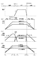
次に、本発明の第1実施の形態による固体電解質型燃料電池システムの動作を説明する。図2は固体電解質型燃料電池システムの動作状況を示すタイミング図である。図2(a)は、固体電解質型燃料電池2の負荷電流(a)を示す。図2(b)は、固体電解質型燃料電池2内の温度(b)と圧力(c)を示す。図2(c)は、燃料ガスの流量(d、e)と、制御弁38の開度を示す。また、蒸気ボイラ62が使用される場合の蒸気の供給量をfで示す。図2(d)は、制御弁42の開度(圧力調節弁)g、再循環ブロワ22の動作(再循環ガス)h、及び制御弁28の開度(供給空気(酸化剤ガス)量)iを示している。
【0049】
はじめに、起動時T0からT3までのうちの昇圧期間である時間T0からT1の間の動作について説明する。
【0050】
固体電解質型燃料電池2が起動されるときには、固体電解質型燃料電池2は常温にある。上記反応式(2)により電力の発生を達成するためには、800℃から1000℃の温度が必要である。また、メタンガスを水素ガスと一酸化炭素ガスに改質するためには水分が必要である。しかしながら、蒸気ボイラ62から水蒸気を供給しなければ、起動時にはシステム内に蒸気は存在しない。そこで、本発明では、メタンガスを改質するために必要な水分は固体電解質型燃料電池2での電力の発生時に生成される水分を用いている。
【0051】
時間T0からT1までの間において、固体電解質型燃料電池2内に設けられたヒーターで温度調節が行われている。また、図2(b)を参照して、時間T0からT1間での間、固体電解質型燃料電池2内の温度bと圧力cは増加し続ける。図2(c)を参照して、制御弁14と16が制御され、水素ガスと窒素ガスの混合ガスdは増加し続ける。図2(d)を参照して、制御弁42の状態gは開状態から閉状態に向かって徐々に閉じられる。しかしながら、完全に閉じられる訳ではない。また、制御弁28の状態iは、わずかに開いた状態が維持される。再循環ブロワ22による循環ガスが徐々に増加する。
【0052】
図2(d)に示されるように、時間T0では、制御弁42がほぼ全開となっているので、エアーコンプレッサー26からの酸化剤ガスは外部熱交換器24を介して固体電解質型燃料電池2に供給される。こうして、図2(b)に示されるように、固体電解質型燃料電池2内の温度bは上昇し、また圧力cも増加する。このとき、制御弁42は大きく開いているので、固体電解質型燃料電池2内の常温の空気は制御弁42を介して排出される。
【0053】
この状態で、制御ユニット200は、図2(c)に示されるように、時間T0において、水素ガス供給ユニット6と窒素ガス供給ユニット8からの水素ガスと窒素ガスを供給するように制御弁14と16を開ける。その後、水素ガスと窒素ガスの供給量が徐々に増加するように制御弁14と16を制御する。こうして、窒素ガスで希釈された水素ガスが燃料ガスとして供給される。水素ガスが供給されるので、前処理器20では改質の必要性はない。そのため、水素ガスを含む燃料ガスは、固体電解質型燃料電池2に供給される。
【0054】
固体電解質型燃料電池2は、燃料ガスと酸化剤ガスとを用いて上記の反応式(2)に基づいてわずかではあるが電力を生成し、また水分(蒸気)を生成する。結果として、生成された水分(蒸気)は配管100−12に供給される。このとき、図2(c)に示されるように、制御弁38は一定の開度であいているが、固体電解質型燃料電池2内の圧力が低いので配管100−12内の排燃料ガスはそれほど制御弁38を介しては外部に排出されない。即ち、配管100−12から固体電解質型燃料電池2の入口側に戻るガス量と弁38を通して系外に排出されるガス量がバランスする。
【0055】
再循環ブロワ22が徐々に循環量を増やすように動作するので、配管100−12内の水分を含む循環ガスは、水素ガスと窒素ガスの混合ガスと混合されて固体電解質型燃料電池2に再び供給されることになる。制御弁42は徐々に閉じる方向に制御されるので、固体電解質型燃料電池2内の圧力cが増加する。
【0056】
こうして、プロセスは、時間T1に進む。時間T1では、固体電解質型燃料電池2内の圧力が所定の値に達する。しかしながら、固体電解質型燃料電池2内の温度が十分にはあがっていないので、まだ定格運転は行われない。
【0057】
時間T1からT2間での間では、外部熱交換器24は動作状態を維持する。図2(c)に示されるように、水素ガスと窒素ガスの混合ガスの流量dは一定に保たれる。また、都市ガスeは供給されていない。図2(d)に示されるように、制御弁42は、閉じてはいないが、低い開度gで保たれる。制御弁28も低い開度で保たれ、固体電解質型燃料電池2に供給される酸化剤ガスの供給量iも一定に保たれる。再循環ブロワ22は、一定の循環ガスを循環させるように動作する。これにより、時間T2で都市ガス(またはメタンガス)での運転が開始されるまでの過渡的処理が行われる。
【0058】
時間T1からT2間での間では、制御弁の制御により、固体電解質型燃料電池2内の圧力は一定値に保たれる。しかしながら、固体電解質型燃料電池2内の温度bは上昇を続ける。
【0059】
時間T2では、固体電解質型燃料電池2内の温度が700℃に達する。言い換えれば、固体電解質型燃料電池2内の温度が700℃に達する時間がT2である。時間T2からT3まで、まだ固体電解質型燃料電池2の昇温期間が続く。
【0060】
時間T2に達すると、図2(c)に示されるように、都市ガスの供給eが始まり、その供給量が徐々に増やされる。また、水素ガスと窒素ガスの混合ガスの供給量は徐々に減らされる。更に、必要があれば、蒸気ボイラ62から蒸気fが供給される。なお、制御弁38は一定の開度jを保ったままである。また、図2(d)を参照して、固体電解質型燃料電池2への酸化剤ガスの供給量iが徐徐に増やされる。また、制御弁42の開度gは、制御ユニット200により制御される。こうして、固体電解質型燃料電池2内の圧力は調整されることができる。
【0061】
このとき、再循環経路内に水分がだいぶ含まれていることになる。しかしながら、その量は定格運転するには不十分な量である。そのため、都市ガスが徐々に供給され、前処理器20により改質されて固体電解質型燃料電池2に供給される。また、負荷電流aが徐々に増やされる。こうして、固体電解質型燃料電池2内では反応式(2)により電力が発生され、水分が生成される。反応式(2)は発熱反応なので、その反応熱により固体電解質型燃料電池2は加熱される。また、負荷電流aが増やされることで、生成水の量が増え、再循環にされる水の量も増加する。
【0062】
すなわち、時間T3にかけて固体電解質型燃料電池2の昇温が完了される。また、再循環ブロワ22は排燃料ガスを再循環している。この状態で、制御弁12が開けられ、都市ガスが燃料ガスとして供給され始める。都市ガスの供給量が徐々に増加するように制御弁12は制御される。一方、水素ガスと窒素ガスの供給量は、都市ガスの供給量が増えるにつれて減少される。
【0063】
このとき、再循環経路内に十分水分があれば、都市ガス(メタンガス)は、前処理器20により反応式(1)に従い水素ガスを含む燃料ガスに予備改質される。しかしながら、水分が不足している場合には、上記ボイラ62から水分を補充する必要がある。本発明では、都市ガスの供給量は当初押さえられている。これは、再循環経路内に存在する水分に見合う量の都市ガスを供給するためである。こうして、都市ガス(メタンガス)は、水素ガスを含む燃料ガスに改質されることができる。また、その水素ガスが電力発生に使用され、水分が生成される。生成された水分は、都市ガスの改質に使用されるという循環が始まることになる。また、固体電解質型燃料電池2の電気出力をアップするために負荷電流が徐々に増加されている。
【0064】
時間T3では、固体電解質型燃料電池2の内部温度は900℃に達する。言い換えれば、固体電解質型燃料電池2の内部温度は900℃に達する時間がT3である。このときには、上記のように、固体電解質型燃料電池2内の圧力cはすでに所定値に達しており、また、固体電解質型燃料電池2内の温度bも900℃に達するので定格運転が開始される。
【0065】
時間T3から時間T4の間では、固体電解質型燃料電池2内のヒーターは、オフされ、定格運転が始まる。図2(c)を参照して、都市ガスの供給量eは一定に保たれる。また、図2(d)に示されるように供給酸素量iも一定に保たれている。水素ガスと窒素ガスの混合ガスは供給されない。図2(d)を参照して、制御弁42は一定の開度gのまま保たれる。また、再循環ブロワ22の循環量hも一定に保たれる。
【0066】
こうして、都市ガスは前処理器20により水素ガスを含む燃料ガスに予備改質されて固体電解質型燃料電池2に供給される。固体電解質型燃料電池2の内部では、燃料ガスに含まれるメタンが水素に改質される。即ち、
CH4 + H2O → CO + 3H2 −Q
の反応が起きる。燃料ガス中の水素ガス及び一酸化炭素とエアーコンプレッサー26から供給される酸化剤ガスとに基づいて反応式(2)による反応が進行する。こうして、定格負荷電流aを取り出すことができる。換言すれば、定格負荷電流aを取り出すことにより、反応の進行を制御することができる。
【0067】
このとき、時間T4から時間T5の間でホットバンキングが起きたとする。ほっとバンキングとは、以上要因によるインターロック作動及び温度維持状態での発電停止等である。従って、図(a)に示されるように、負荷電流aの取り出しは停止される。時間T4からT5の間では、固体電解質型燃料電池2内のヒーターによる温度調節が開始される。また、図2(c)に示されるように、都市ガスの供給eは停止される。代わって、水素ガスと窒素ガスの混合ガスdが供給される。制御弁38は一定の開度jを維持する。また、図2(d)に示されるように、再循環ブロワ22は動作を続ける。また、制御弁42は一定の開度gを維持する。酸化剤ガスの供給iは停止される。
【0068】
時間T5でホットバンキングが終了すると、都市ガスの供給eが再開され、水素ガスと窒素ガスの混合ガスの供給dは停止される。また、制御弁28は、閉じられていたとしても元の開度に戻され、供給酸素量iは元の状態に戻される。こうして、システム全体として定格運転の状態に戻される。
【0069】
時間T6で、定格運転が終了される。このとき、直ちに電源が切られると、配管内に排燃料ガスと酸化剤ガスが残ったままになってしまう。また、都市ガスが残っていれば、改質が行われないので、都市ガスがそのまま燃料電池モジュールに入ることになる。都市ガスがそのまま燃料電池モジュールに入ると炭化水素ガスが熱分解されて炭素が燃料電池モジュールに付着することになる。この炭素は、燃料電池モジュールの効率を低下させることになる。そのため、運転終了時には、配管内の燃料ガスをすべて排気することが必要である。
【0070】
時間T6では、図2(c)に示されるように、制御弁12が制御され、都市ガスの供給eは急激に減少される。代わって、水素ガスと窒素ガスの混合ガスの供給dが開始される。この供給量は、時間T1からT2の間の供給量とほぼ同じである。図2(d)に示されるように、供給酸素量iも徐々に減らされる。図2(a)に示されるように、都市ガスが流れている間に負荷電流aが下げられる。また、制御弁42の開度も減らされる。一方、再循環ブロワ22の動作は定格運転の時と同じである。
【0071】
こうして、固体電解質型燃料電池2の内部温度bは徐々に下がり始める。また、このとき、都市ガスの供給が停止されると、固体電解質型燃料電池2内のヒーターは温度調整を開始する。
【0072】
こうして、固体電解質型燃料電池2の内部温度が700℃以下となると、時間T7で、降圧プロセスが始まる。固体電解質型燃料電池2内のヒーターは温度調整したままである。図2(c)に示されるように、水素ガスと窒素ガスの混合ガスの流量dが徐々に減るように制御弁14、16が制御される。同時に再循環ブロワ22の循環量が減らされる。一方、制御弁38は一定の低い開度jを保ったままである。また、図2(d)に示されるように、供給酸素量iは絞られる。一方、制御弁42の開度gは増加される。こうして、酸化剤ガスの圧力が下がり、固体電解質型燃料電池2内の燃料ガスは排出される。最終的に、固体電解質型燃料電池2の温度bが常温近くに戻り、また、内部圧力cが大気圧に戻ったとき(時間T8)、システムの運転は終了される。
【0073】
次に、本発明の第1実施の形態による固体電解質型燃料電池システムの第2の動作例を説明する。図3は固体電解質型燃料電池システムの第2の動作状況を示すタイミング図である。図3(a)は、固体電解質型燃料電池2の負荷電流oを示す。図3(b)は、固体電解質型燃料電池2内の温度pと圧力qを示す。図3(c)は、水素ガスと窒素ガスの混合ガスの流量rと都市ガスの流量sと、制御弁38の開度uを示す。また、蒸気ボイラ62が使用される場合の蒸気の供給量をtで示す。図3(d)は、制御弁42の開度(圧力調節弁)v、再循環ブロワ22の動作(再循環ガス)x、及び制御弁28の開度に対応する供給空気(酸化剤ガス)量)wを示している。
【0074】
はじめに、起動時T10からT11までの昇圧昇温期間の動作について説明する。
【0075】
時間T10からT11までの間において、固体電解質型燃料電池2内のヒーターにより温度調節が行われている。また、図3(c)を参照して、制御弁14と16が制御され、水素ガスと窒素ガスの混合ガスrは増加し続ける。図3(d)を参照して、制御弁42の開度vは一定に保たれる。また、制御弁28の状態wは、徐々に開度が増加され、供給酸素量wは増加する。再循環ブロワ22による循環ガスxも徐々に増加する。こうして、図3(b)に示されるように、時間T10からT11間での間、固体電解質型燃料電池2内の温度bと圧力cは増加し続ける。
【0076】
時間T10では、固体電解質型燃料電池2内のヒーターにより温度調節が行われているので、図3(b)に示されるように、固体電解質型燃料電池2内の温度bは上昇する。また、制御弁42の開度vは一定に保たれているので、エアーコンプレッサー26からの酸化剤ガスは外部熱交換器24を介して固体電解質型燃料電池2に供給される。更に、混合ガスrが供給されている。こうして、また圧力qも増加する。このとき、制御弁42は一定の開度vにあるので、固体電解質型燃料電池2内の常温の酸化剤ガスは制御弁42を介して排出される。
【0077】
この状態で、図3(c)に示されるように、制御ユニット200により水素ガスと窒素ガスの供給量が徐々に増加するように制御弁14と16が制御される。こうして、水素ガスと窒素ガスの混合ガス、即ち窒素ガスで希釈された水素ガスが燃料ガスとして供給される。水素ガスを含むガスが供給されるので、前処理器20では改質の必要性はない。そのため、水素ガスを含む燃料ガスは、そのまま固体電解質型燃料電池2に供給される。
【0078】
固体電解質型燃料電池2は、燃料ガスと酸化剤ガスとを用いて上記の反応式(2)に基づいてわずかではあるが電力を生成し、また水分(蒸気)を生成する。結果として、生成された水分(蒸気)は配管100−12に供給される。このとき、図3(c)に示されるように、制御弁38は一定の開度uであいているが、固体電解質型燃料電池2内の圧力が低いので配管100−12内の排燃料ガスはそれほど制御弁38を介しては外部に排出されない。
【0079】
再循環ブロワ22が徐々に循環量をx増やすように動作するので、配管100−12内の水分を含む循環ガスは循環され、水素ガスと窒素ガスの混合ガスと混合されて固体電解質型燃料電池2に再び供給されることになる。
【0080】
こうして、プロセスは、時間T11に進む。時間T11では、固体電解質型燃料電池2内の圧力qが所定の値(この例では3atg)に達する。また、固体電解質型燃料電池2の内部温度pも900に上昇する。しかしながら、この状態は都市ガスを使用する定格運転ではない。
【0081】
時間T11からT12間での間では、外部熱交換器24の出力は保たれる。図3(c)に示されるように、水素ガスと窒素ガスの混合ガスの流量rは一定に保たれる。また、都市ガスsは供給されていない。図3(d)に示されるように、制御弁42は、一定の開度uを保っている。また、図3(d)に示されるように、制御弁28は、大きい開度wで保たれ、大量の空気が供給されている。再循環ブロワ22は、一定の循環ガスを循環させるように動作する。これにより、時間T12で都市ガス(またはメタンガス)での運転が開始されるまでの過渡的処理(ホットスタンバイ処理)が行われる。こうして、時間T11からT12間での間では、図3(b)に示されるように、固体電解質型燃料電池2内の圧力qは一定値に保たれ、温度pも一定に保たれるホットスタンバイ状態が保たれる。
【0082】
時間T12から時間T13までの間に、燃料の切り替えが行われる。すなわち、時間T12に達すると、固体電解質型燃料電池2内のヒーターによる温度調整は停止される。また、図3(c)に示されるように、都市ガスの供給sが始まり、その供給量が徐々に増やされる。また、水素ガスと窒素ガスの混合ガスの供給量rは徐々に減らされる。更に、必要があれば、蒸気ボイラ62から蒸気tが供給される。なお、制御弁38は一定の開度jを保ったままである。また、図3(d)を参照して、制御弁28の開度wは、大きな開度で保たれる。こうして、固体電解質型燃料電池2へは十分に酸化剤ガスwが供給されることができる。また、制御弁42の開度vは、制御ユニット200により一定に保たれる。こうして、固体電解質型燃料電池2内の圧力は調整されることができる。
【0083】
時間T12では、再循環経路内に水分がだいぶ含まれていることになる。しかしながら、その量は定格運転するには不十分な量である。そのため、都市ガスsが徐々に供給され、前処理器20により予備改質されて固体電解質型燃料電池2に供給される。また、負荷電流oが徐々に増やされる。こうして、固体電解質型燃料電池2内では反応式(2)により電力が発生され、水分が生成される。反応式(2)は発熱反応なので、その反応熱により固体電解質型燃料電池2は加熱される。
【0084】
すなわち、時間T13にかけて再循環経路内の水分が十分に確保されることになる。すなわち、外部熱交換器24を介して酸化剤ガスwが固体電解質型燃料電池2に供給され続ける。また、再循環ブロワ22は排燃料ガスを再循環している。この状態で、制御弁12が開けられ、都市ガスsが燃料ガスとして供給され始める。都市ガスの供給量が徐々に増加するように制御弁12は制御される。一方、水素ガスと窒素ガスの混合ガスの供給量rは、都市ガスの供給量sが増えるにつれて減少される。
【0085】
このとき、再循環経路内に十分水分があれば、都市ガス(メタンガス)は、反応式(1)により水素ガスを含む燃料ガスが前処理器20により生成される。しかしながら、水分が不足している場合には、上記ボイラ62から水分tを補充する必要がある。本発明では、都市ガスの供給量は当初押さえられている。これは、再循環経路内に存在する水分に見合う量の都市ガスを供給するためである。こうして、都市ガス(メタンガス)は、水素ガスを含む燃料ガスに改質されることができる。また、その水素ガスが電力発生に使用され、水分が生成される。生成された水分は、都市ガスの改質に使用されるという循環が始まることになる。また、このとき、固体電解質型燃料電池2の負荷電流oが徐々に増加されている。これにより、固体電解質型燃料電池2での反応式(2)による反応の速度が制御される。
【0086】
時間T13では、固体電解質型燃料電池2の内部温度は900℃に達する。言い換えれば、固体電解質型燃料電池2の内部温度は900℃に達する時間がT13である。このときには、上記のように、固体電解質型燃料電池2内の圧力qはすでに所定値に達しており、また、固体電解質型燃料電池2内の温度pも900℃に達しているので、定格運転が開始される。
【0087】
時間T13から時間T14の間では、泥各運転が開始される。固体電解質型燃料電池2内のヒーターはオフされる。図3(c)を参照して、都市ガスの供給量sは一定に保たれる。制御弁38は一定の開度uを保つ。水素ガスと窒素ガスの混合ガスは供給されない。図3(d)を参照して、供給酸素量wも一定である。再循環ブロワ22の循環量xも一定に保たれる。なお、制御弁42の開度vは一定に保たれたままである。
【0088】
こうして、都市ガスは前処理器20により水素ガスを含む燃料ガスに予備改質されて固体電解質型燃料電池2に供給される。固体電解質型燃料電池2の内部では、燃料ガスに含まれる改質されていないメタンガスがさらに水素ガスに改質される。燃料ガス中の水素ガスと一酸化炭素ガスとエアーコンプレッサー26から供給される酸化剤ガスとに基づいて反応式(2)による反応が進行する。こうして、定格負荷電流oを取り出すことができる。換言すれば、定格負荷電流oを取り出すことにより、反応の進行を制御することができる。
【0089】
時間T14で、定格運転が終了される。このとき、直ちに電源が切られると、配管内に排燃料ガスと酸化剤ガスが残ったままになってしまう。また、都市ガスが残っていれば、改質が行われないので、都市ガスがそのまま燃料電池モジュールに入ることになる。都市ガスがそのまま燃料電池モジュールに入ると炭化水素ガスが熱分解されて炭素が燃料電池モジュールに付着することになる。この炭素は、燃料電池モジュールの効率を低下させることになる。そのため、運転終了時には、配管内の燃料ガスをすべて排気することが必要である。
【0090】
時間T14では、負荷電流0が減少される。こうして、図3(c)に示されるように、制御弁12が制御され、都市ガスの供給sは急激に減少される。代わって、水素ガスと窒素ガスの混合ガスの供給量rが急激に増加される。また、図3(d)に示されるように、制御弁28の開度wは一定に保たれる。制御弁42の開度vは一定に保たれたままである。再循環ブロワ22の動作は定格運転の時と同じである。このため、固体電解質型燃料電池2内の温度pと圧力qは変化しない。
【0091】
こうして、負荷電流oが無くなり、都市ガスの供給が無くなると、時間T15で図3(d)に示されるように、混合ガスの供給量rと酸素供給量wは徐々に減らされる。再循環ブロワ22の循環される排燃料ガスの量も徐々に減らされる。一方、制御弁42の開度vは一定に保たれたままである。また、固体電解質型燃料電池2内のヒーターによる温度調整が再開される。こうして、固体電解質型燃料電池2の内部温度pは徐々に下がり始める。こうして、最終的に、固体電解質型燃料電池2の温度pが常温近くに戻り、また、内部圧力qが大気圧に戻ったとき(時間T16)、システムの運転は終了される。
【0092】
図4は、本発明の第2の実施の形態による固体電解質型燃料電池システムの構成を示すブロック図である。この固体電解質型燃料電池システムは発電量は100KW級であり、燃料電池とガスタービン発電機とがコンバインドされている。なお、簡略化のため、図1に示された制御ユニット200内の一部のユニットは図面では省略されている。
【0093】
図4を参照して、第2の実施の形態による固体電解質型燃料電池システムは、主に、固体電解質型燃料電池2、都市ガス供給ユニット4、蒸気供給ユニット72、水素ガス供給ユニット6、窒素ガス供給ユニット6、置換ガス供給ユニット10、制御弁12−18、前処理器76、再循環ブロワ22、外部熱交換器94、エアーコンプレッサー26、制御ユニット200(図示せず)、燃焼器82,ガスタービン(G/T)88,温水ボイラ92からなる。第1の実施の形態におけるヒーターに代えて起動用バーナー78が固体電解質型燃料電池2には設けられている。都市ガス供給ユニット4、水素ガス供給ユニット、6、窒素ガス供給ユニット8、置換ガス供給ユニット10に対して制御ユニット200により制御される制御弁が設けられているが、図面では省略されている。制御ユニット200は、固体電解質型燃料電池システムの全体の動作を制御する。
【0094】
都市ガス供給ユニット4から出力される都市ガスは制御弁を介して配管100−1に燃料ガスとして供給される。水素ガス供給ユニット6から出力される水素ガスは制御弁を介して配管100−1に燃料ガスとして供給される。窒素ガス供給ユニット8から出力される窒素ガスは制御弁を介して配管100−1に供給される。この制御弁は、制御ユニット200により制御され、固体電解質型燃料電池2の起動時及び運転終了時に窒素ガスを配管100−1に供給する。この窒素ガスは、水素ガス供給ユニット6から配管100−1に供給される水素ガスを希釈するために使用される。置換ガス供給ユニット10から出力される置換ガスは制御弁を介して配管100−1に供給される。蒸気供給ユニット72から出力される蒸気は制御弁を介して配管100−1に供給される。
【0095】
水素供給ユニット6と窒素供給ユニット8の制御弁は、制御ユニット200により制御され、固体電解質型燃料電池2に異常が発生したとき、あるいは固体電解質型燃料電池2の運転を停止するとき、固体電解質型燃料電池2内、及び関連する配管内の燃料ガスを排出するために使用される。
【0096】
配管100−1に供給されたガスは、配管100−14内の循環ガスと共に配管100−4を介して前処理器76に供給される。前処理器76は、第1の実施の形態における前処理器20と同じ機能を有する。燃料ガスが固体電解質型燃料電池2に供給される前に、配管100−4内のガスに含まれる都市ガス(炭化水素ガス)を上記反応式(1)に従って予備改質する。改質されたガスは配管100−6を介して固体電解質型燃料電池2に供給される。
【0097】
起動用エアーコンプレッサ98は、空気を制御弁120を介して配管110−22,110−24を介して配管110−30に送る。エアーコンプレッサー(A/C)26、制御ユニット200の制御の下、空気を圧縮して酸化剤ガスとして配管110−30に供給する。配管110−30内の酸化剤ガスは、外部熱交換器(AH)94に供給される。外部熱交換器94は、制御ユニット200の制御の下、配管110−30を介して供給される酸化剤ガスを配管110−28から供給される高温ガスの熱により加熱して配管110−32に供給する。
【0098】
制御ユニット200は、温度制御を行い、外部熱交換器94からの酸化剤ガスの温度が高いときには、制御弁32を開けて加熱前の空気を配管110−32に供給する。こうして、固体電解質型燃料電池2に供給されるべき酸化剤ガスの温度を調整することができる。
【0099】
配管110−32内の空気は、制御ユニット200により制御される制御弁128を介して燃焼器82に供給される。また、配管110−32内の酸化剤ガスは、制御ユニット200により制御される流量調節弁(流調弁)28を介して固体電解質型燃料電池2に供給される。この例では、流調弁28と並列にバイパス弁122が設けられている。制御ユニット200の圧力調整器は、センサーにより検出された空気圧に基づいて制御弁28の開閉度を制御する。
【0100】
固体電解質型燃料電池2は、第1の実施の形態と同様に、内部に改質機能を有している。例えば、反応式(1)に従って、都市ガス中に含まれるメタンガスを水素ガスと一酸化炭素ガスを含むガスに改質することができる。固体電解質型燃料電池2は、高温動作型の燃料電池であり、動作温度は、約800℃から1000℃である。固体電解質型燃料電池2は、配管100−6を介して供給される燃料ガスと外部熱交換器94から供給される加熱酸化剤ガスとを用いて、上記反応式(2)に従って水素ガスと酸化剤ガスから電力を発生し、水を生成する。発生された電力は外部に取り出されるが、図示はしていない。
【0101】
この反応は発熱反応であるが、固体電解質型燃料電池2の起動時には固体電解質型燃料電池2は常温にある。従って、起動時には固体電解質型燃料電池2を動作温度に保つための熱源として上記反応熱を利用することはできない。このため、起動時にはバーナー78により固体電解質型燃料電池2を加熱している。外部熱交換器94で酸化剤ガスを加熱し、その熱を用いて固体電解質型燃料電池2の温度を維持する。同時に、反応式(2)の発熱反応による反応熱を利用して固体電解質型燃料電池2の温度を維持する。
【0102】
上記反応式(2)に従う反応後の排燃料ガスは、配管100−8に出力される。また、上記反応式に従う反応後の排酸化剤ガスは、配管110−40に出力される。
【0103】
排酸化剤ガスは、外部熱交換器94を介して配管110−40に出力される。排酸化剤ガスもかなりの高温状態にあるので、この排酸化剤ガスは外部熱交換器94に供給される酸化剤ガスを加熱するために使用される。従って、外部熱交換器94から出力される排酸化剤ガスは温度が下がっている。また、排酸化剤ガスは、制御ユニット200により制御される遮断弁126を介して燃焼器82に供給される。遮断弁126の開閉を制御することにより、燃焼器82とガスタービン88を通るラインと通らないバイパスラインとの切り替えが可能となる。従って、固体電解質型燃料電池2の起動とガスタービンの起動を別々に行う際に有効である。
【0104】
その後、排酸化剤ガスは、制御ユニット200により制御される圧力調節弁42を介して排気筒46から排気される。制御ユニット200の圧力調整器は、固体電解質型燃料電池2内のガスの圧力を検出し、圧力調節弁42の開閉度を制御する。こうして、固体電解質型燃料電池2内の圧力が一定に保たれることになる。
【0105】
また、反応後の排燃料ガスは、固体電解質型燃料電池2から配管100−8に出力される。排燃料ガスには、上記の反応により生成された水分としての蒸気と、改質器により生成されたが反応に使用されなかった水素ガス、改質により生成された一酸化炭素ガス、改質されないままの燃料ガスなどが含まれている。
【0106】
排燃料ガスは、配管100−12に供給され、また、制御ユニット200により制御される制御弁86と配管110−44を介して燃焼器82に供給される。更に、制御ユニット200により制御される制御弁84を介して冷却器34に供給され、冷却器34により冷却された後、トラップ36を介して排気筒44から排気される。トラップ34は、排燃料ガスに含まれている蒸気、及び可溶性のガスなどを除去するために使用される。こうして、制御弁86と84を切り換えることにより、燃焼器82とガスタービンG/T88を通るラインと通らないバイパスラインとの切り換えが可能となり、固体電解質型燃料電池2の起動とガスタービンG/T88の起動を別々に実行する際に有効である。
【0107】
トラップ36と排気筒44の間には制御ユニット200により制御される差圧調節弁38が設けられている。制御ユニット200の圧力差調整器は供給燃料ガスの圧力と固体電解質型燃料電池2の内部圧力との差に基づいて差圧調節弁38の開閉度を制御する。この結果、固体電解質型燃料電池2に供給される燃料ガスの圧力は、酸化剤ガスの圧力より所定値、この例では50っmAqだけ高い状態に保たれることができる。
【0108】
配管100−12に供給された排燃料ガスは、再循環ブロワ22により配管100−14と制御ユニット200により制御される制御弁132を介して配管100−4に供給される。配管100−4内の燃料ガスは、供給ユニット4,6,8,10,72から供給される燃料ガスと共に前処理器76に供給される。
【0109】
制御弁(図示せず)は、再循環ブロワ22をバイパスする経路に設けられている。制御ユニット200の圧力調整器は、この制御弁の開閉度を制御する。これにより、配管100−12内の燃料ガスは、流量制御されて配管100−4に供給されることになる。
【0110】
配管100−1内の水素ガスあるいは都市ガスは、固体電解質型燃料電池2のバーナー78に供給され、固体電解質型燃料電池2を加熱するために使用される。また、配管100−1内の水素ガスあるいは都市ガスは制御ユニット200により制御される制御弁80を介して燃焼器2に供給される。
【0111】
燃焼器82からの燃焼ガスはガスタービン88に供給され、発電のために使用される。ガスタービンG/T88には、エアーコンプレッサー26から圧縮空気も供給されている。ガスタービン88からの排ガスは外部熱交換器94に供給され、それに供給される空気を加熱するために使用される。熱交換器94を通過した排ガスは温水ボイラ92に供給される。温水ボイラ92は温水を生成する。温水ボイラに代えて蒸気ボイラを使用すれば、生成された蒸気により、蒸気タービンを回すことも可能である。まあ、その蒸気の一部を固体電解質型燃料電池2の入口側に供給すれば、改質よう蒸気として使用することもできる。
【0112】
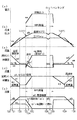
次に、本発明の第2実施の形態による固体電解質型燃料電池システムの動作を説明する。図5は固体電解質型燃料電池システムの動作状況を示すタイミング図である。図5(a)は、固体電解質型燃料電池2の負荷電流(aa)を示す。図5(b)は、固体電解質型燃料電池2内の温度(ab)と圧力(ac)を示す。図5(c)は、水素ガスと窒素ガスの混合ガスの流量aeと、都市ガス流量agと、差圧調節弁38の開度adと、蒸気供給ユニット72の供給量をafで示す。図5(d)は、ガスタービン88の出口空気量ah、酸化剤ガスのための圧力調節弁42の開度ai、及び流調弁28による供給空気(酸化剤ガス)量ajを示している。また、図5(e)は、再循環ブロワ22の動作(再循環ガス)al、ガスタービン88の燃焼器82に水素ガスまたは都市ガスを供給するための制御弁80、128の複合の開度ak、バーナー78に供給される水素ガスまたは都市ガスの流量amを示す。
【0113】
はじめに、起動時T20からT21まで期間の動作からシステムの動作を説明する。
【0114】
時間T20で固体電解質型燃料電池システムが起動されるときには、固体電解質型燃料電池2は常温常圧にある。上記反応式(2)により電力の発生を達成するためには、800℃から1000℃の温度が必要である。また、都市ガス(高水素ガス)を水素ガスと一酸化炭素ガスに改質するためには水分が必要である。しかしながら、水蒸気を供給しなければ、起動時にはシステム内に蒸気は存在しない。そこで、本発明では、都市ガスを改質するために必要な水分は固体電解質型燃料電池2での電力の発生時に生成される水分を用いている。
【0115】
時間T20では、図5(e)に示されるように制御弁80は開いており、図5(c)に示されるように、水素ガスと窒素ガスの混合ガスaeは、一定量が出力されていて、制御弁80を介して燃焼器82に供給されている。燃焼器には、起動用エアーコンプレッサー98からの空気が制御弁120、外部熱交換器94、制御弁128を介して燃焼器82に供給されている。燃焼器82の燃焼ガスはガスタービン88に供給される。こうして、ガスタービンによる発電は起動される。
【0116】
時間T20からT21までの間において、図5(c)を参照して、水素ガスと窒素ガスの混合ガスaeは一定量が供給され続けている。また、差圧調節弁38は開度adが徐々に減少されている。図5(d)を参照して、ガスタービン88の出口の空気ahは一定量が供給されている。また、圧力調節弁42の開度aiは徐々に減少される。一方、空気供給量ajで低いレベルで一定である。図5(e)に示されるように、再循環ブロワ22は再循環量を徐々に増やす。こうして、図5(b)を参照して、時間T20からT21間での間、固体電解質型燃料電池2内の温度abと圧力acは増加し続ける。
【0117】
次に、時間T21から時間T22までは、図5(c)に示されるように、差圧調節弁38の開度adは引き続き減少している。混合ガスaeの供給量は一定である。図5(d)を参照して、圧力調節弁42の開度aiは引き続き減少している。空気供給量ajは一定である。
【0118】
図5(e)を参照して、混合ガスaeの一部はバーナ燃料amとしてバーナー78に供給され、燃焼される。これにより固体電解質型燃料電池2の内部温度は上昇される。また、図5(d)に示されるように、時間T20からT22の間では、制御弁28は開いているので、エアーコンプレッサー98からの酸化剤ガスは外部熱交換器94で加温された後、固体電解質型燃料電池2に供給される。こうして、図5(b)に示されるように、固体電解質型燃料電池2内の温度abは上昇し、また圧力acも増加する。このとき、圧力調節弁42は大きく開いているので、固体電解質型燃料電池2内の常温の空気は圧力調節弁42を介して排出される。
【0119】
この状態で、水素ガスと窒素ガスの供給量aeは一定に保たれている。こうして、窒素ガスで希釈された水素ガスが燃料ガスとして供給される。水素ガスが供給されるので、前処理器76では改質の必要性はない。そのため、水素ガスを含む燃料ガスは、固体電解質型燃料電池2に供給される。
【0120】
固体電解質型燃料電池2は、燃料ガスと酸化剤ガスとを用いて上記の反応式(2)に基づいてわずかではあるが電力を生成し、また水分(蒸気)を生成する。結果として、生成された水分(蒸気)は配管100−12に供給される。このとき、図5(c)に示されるように、差圧調節弁38の開度adは下がっているが、固体電解質型燃料電池2内の圧力が低いので配管100−12内の排燃料ガスはそれほど差圧調節弁38を介しては外部に排出されない。
【0121】
再循環ブロワ22が徐々に循環量を増やすように動作しているので、配管100−12内の水分を含む循環ガスは、水素ガスと窒素ガスの混合ガスと混合されて固体電解質型燃料電池2に再び供給されることになる。圧力調節弁42は徐々に閉じる方向に制御されるので、固体電解質型燃料電池2内の圧力cが増加する。
【0122】
こうして、プロセスは、時間T22に進む。時間T22から時間T23では、固体電解質型燃料電池2内の圧力が所定の値に達する。しかしながら、固体電解質型燃料電池2内の温度が十分にはあがっていないので、まだ定格運転は行われない。
【0123】
時間T22からT23間での間では、外部熱交換器94は動作状態を維持する。また、図5(e)に示されるように、バーナー78は燃焼を続けている。このため、図5(b)に示されるように、固体電解質型燃料電池2内の温度abは徐々に上昇する。
【0124】
図5(c)に示されるように、水素ガスと窒素ガスの混合ガスの流量aeは一定に保たれている。また、都市ガスagは供給されていない。都市ガスagは、第1の実施の形態と同様に、定格運転が開始されるように供給される。図5(d)に示されるように、圧力調節弁42は、閉じられ、そのままの状態を運転停止まで保持する。制御弁28は期間T21からT22までのときより大きい開度ajを保つように制御される。再循環ブロワ22は、一定量の循環ガスを循環させるように動作する。これにより、時間T23で都市ガス(またはメタンガス)での運転が開始されるまでの過渡的処理が行われる。
【0125】
時間T22からT25の間では、制御弁の制御により、固体電解質型燃料電池2内の圧力は一定値に保たれる。時間T23では、固体電解質型燃料電池2内の温度が700℃に達する。言い換えれば、固体電解質型燃料電池2内の温度が700℃に達する時間がT23である。時間T23からT25まで、まだ固体電解質型燃料電池2の昇温期間が続く。
【0126】
時間T23に達すると、バーナー78による加熱は押さえられる。また、図5(c)に示されるように、都市ガスの供給agが始まり、その供給量が徐々に増やされる。また、水素ガスと窒素ガスの混合ガスの供給量は徐々に減らされる。更に、必要があれば、蒸気ボイラ62から蒸気afが供給される。なお、差圧調節弁38は時間T23で閉じられ、運転停止まで保持される。また、図5(d)を参照して、固体電解質型燃料電池2への空気供給量ajが徐々に増やされる。また、圧力調節弁42の開度aiは、時間T22から閉じられたままである。また、再循環ブロワ22は、時間T22から全開で運転されている。
【0127】
図5(e)を参照して、燃焼器82への燃料ガスと酸化剤ガスの供給は時間T23からT25の間で徐々に減らされる。また、制御ユニット200により制御弁80,84,86,122,126、128は連携して制御される。こうして固体電解質型燃料電池2に供給される酸化剤ガスの量ajの増加と同時に、バイパス経由での燃料ガスの供給は減少される。一方、別の経路での排燃料ガスの燃焼器82への供給量、及び排酸化剤ガスの燃焼器82への供給量が制御される。
こうして、固体電解質型燃料電池2内の圧力は調整されることができる。
【0128】
このとき、時間T23以後バーナー78での燃焼は徐々に減らされ、時間T23とT25の間のT24でバーナー78は停止される。これにより、固体電解質型燃料電池2の外的な加温は止まり、反応熱により加温され、また保たれることになる。
【0129】
すなわち、再循環経路内に水分がだいぶ含まれていることになる。しかしながら、その量は定格運転するには不十分な量である。そのため、都市ガスが徐々に供給され、前処理器76により予備改質されて固体電解質型燃料電池2に供給される。また、負荷電流aaが徐々に増やされる。こうして、固体電解質型燃料電池2内では反応式(2)により電力が発生され、水分が生成される。反応式(2)は発熱反応なので、その反応熱により固体電解質型燃料電池2は加熱される。
【0130】
T25にかけて固体電解質型燃料電池2の昇温が完了される。また、再循環ブロワ22は排燃料ガスを再循環している。時間時間T23からT25にかけて都市ガスagが供給され始める。都市ガスの供給量が徐々に増加するように制御される。一方、水素ガスと窒素ガスの混合ガスaeの供給量は、都市ガスの供給量agが増えるにつれて減少される。
【0131】
このとき、再循環経路内に十分水分があれば、都市ガス(メタンガス)は、反応式(1)により水素ガスを含む燃料ガスが前処理器76により生成される。しかしながら、水分が不足している場合には、蒸気供給ユニット72から水分を補充する必要がある。本発明では、都市ガスの供給量は当初押さえられている。これは、再循環経路内に存在する水分に見合う量の都市ガスを供給するためである。こうして、都市ガスは、水素ガスと一酸化炭素ガスを含む燃料ガスに改質されることができる。また、その水素ガスと一酸化炭素ガスが電力発生に使用され、水分が生成される。生成された水分は、都市ガスの改質に使用されるという循環が始まることになる。また、このとき、固体電解質型燃料電池2の負荷電流が徐々に増加されている。
【0132】
時間T25では、固体電解質型燃料電池2の内部温度は900℃に達する。言い換えれば、固体電解質型燃料電池2の内部温度は900℃に達する時間がT25である。このときには、上記のように、固体電解質型燃料電池2内の圧力acはすでに所定値に達しており、また、固体電解質型燃料電池2内の温度bも900℃に達するので定格運転が開始される。
【0133】
時間T25から時間T28の間では、バーナー78は、オフされる。図5(c)を参照して、都市ガスの供給量agは一定に保たれる。差圧調節弁38は閉じられたままである。水素ガスと窒素ガスの混合ガスaeは供給されない。図5(d)を参照して、圧力調節弁42は閉じられたままである。酸素供給量aj一定にに保たれる。図5(e)に示されるように、再循環ブロワ22の循環量alも一定に保たれる。
【0134】
こうして、都市ガスは前処理器76により水素ガスを含む燃料ガスに予備改質されて固体電解質型燃料電池2に供給される。固体電解質型燃料電池2の内部では、燃料ガスに含まれる改質されていない都市ガス成分(メタンガス)がさらに水素ガスに改質される。燃料ガス中の水素ガス、一酸化炭素ガスとエアーコンプレッサー98から供給される酸化剤ガスとに基づいて反応式(2)による反応が進行する。
【0135】
このとき、時間T26から時間T27の間でホットバンキングが起きたとする。時間T26からT27の間では、図5(c)に示されるように、都市ガスの供給agは停止される。代わって、水素ガスと窒素ガスの混合ガスaeが一定量供給される。差圧調節弁38は一定の開度adを維持するように制御される。このとき、弁38が使用されるときは、弁86と84との間で切り換えが必要である。また、図5(d)に示されるように、圧力調節弁42は閉じられたままである。供給空気量ajは一定のままである。図5(e)を参照して、制御弁80と128が開けられ、燃焼ガスが燃焼器82に供給される。また、再循環ブロワ22は動作を続ける。
【0136】
時間T27でホットバンキングが終了すると、図5(c)に示されるように、都市ガスの供給agが再開され、水素ガスと窒素ガスの混合ガスの供給aeは停止される。また、差圧調節弁38は、閉じられる。こうして、システム全体として定格運転の状態に戻される。
【0137】
時間T28で、定格運転が終了される。このとき、直ちに電源が切られると、配管内に排燃料ガスと酸化剤ガスが残ったままになってしまう。また、都市ガスが残っていれば、改質が行われないので、都市ガスがそのまま燃料電池モジュールに入ることになる。都市ガスがそのまま燃料電池モジュールに入ると炭化水素ガスが熱分解されて炭素が燃料電池モジュールに付着することになる。この炭素は、燃料電池モジュールの効率を低下させることになる。そのため、運転終了時には、配管内の燃料ガスをすべて排気することが必要である。
【0138】
時間T28では、図5(a)に示されるように、負荷電流aaは当然減少される。図5(c)に示されるように、都市ガス4の供給agは急激に減少される。代わって、水素ガスと窒素ガスの混合ガスaeは一定量供給される。この供給量は、時間T20からT23の間の供給量とほぼ同じである。また、都市ガスの供給が止まると、差圧調節弁38はT22とT23の期間とほぼ同じ開度を持って開けられる。また、図5(d)に示されるように、空気供給量ajが徐々に減らされるように、制御弁28が制御され、同時に制御弁128も制御される。また、圧力調節弁42は閉じられたままである。図5(e)を参照して、再循環ブロワ22の動作は定格運転の時と同じである。また、制御弁80が開けられる。
【0139】
こうして、固体電解質型燃料電池2の内部温度が700℃以下となると、時間T29で、降圧プロセスが始まる。図5(c)に示されるように、水素ガスと窒素ガスの混合ガスの流量aeは一定のままである。同時に差圧調節弁38の開度adは所定の開度に向かって増加される。また、図5(d)を参照して、圧力調節弁42の開度aiも所定の開度に向かって増加される。こうして、燃料ガスと酸化剤ガスは排出され、固体電解質型燃料電池2内の圧力が下がる。最終的に、固体電解質型燃料電池2の温度bが常温近くに戻り、また、内部圧力cが大気圧に戻ったとき(時間T30)、システムの運転は終了される。この結果、混合ガスaeの供給は停止される。制御弁80も閉じられる。
【0140】
【発明の効果】
以上説明したように、本発明の固体電解質型燃料電池システムによれば、安定に電力を取り出すことができる。また、起動時に水蒸気を供給する必要が無く、ボイラーなどの付帯設備を設ける必要がない。更に、起動時及び停止時に炭素による燃料電池モジュールの汚染を防止することができる。
【0141】
また、最小限のシステム構成でガスタービンを用いて燃料ガスを有効に利用することにより発電効率を高めることができる。
【図面の簡単な説明】
【図1】図1は、本発明の第1の実施の形態による10KW級固体電解質型燃料電池システムの構成を示すブロック図である。
【図2】図2は、本発明の第1の実施の形態による固体電解質型燃料電池システムの第1の動作例を示すタイミング図である。
【図3】図3は、本発明の第1の実施の形態による固体電解質型燃料電池システムの第2の動作例を示すタイミング図である。
【図4】図4は、本発明の第2の実施の形態による100KW級固体電解質型燃料電池システムの構成を示すブロック図である。
【図5】図5は、本発明の第2の実施の形態による固体電解質型燃料電池システムの動作例を示すタイミング図である。
【符号の説明】
2:固体電解質型燃料電池
4:都市ガス
6:水素ガス
8:窒素ガス
20:前処理器
22:再循環ブロワ
24、94:外部熱交換器
26:エアーコンプレッサー
82:燃焼器
88:ガスタービン
92:温水ボイラ[0001]
BACKGROUND OF THE INVENTION
The present invention relates to a solid oxide fuel cell system.
[0002]
[Prior art]
An example of the structure of a high-temperature solid electrolyte fuel cell is known from Japanese Patent Laid-Open No. 9-129256. The operating temperature of the high temperature solid oxide fuel cell is assumed to be 800 ° C to 1000 ° C. In this reference, the cell tube (fuel cell module) is fixed to the upper tube plate and the lower tube plate and extends below the lower tube plate. The fuel gas containing moisture is supplied between the top plate and the upper tube plate. The lower tube sheet is filled with oxidant gas. The fuel gas is supplied to the cell tube and used for power generation. The exhausted fuel gas after power generation is discharged from the cell tube between the upper tube sheet and the lower tube sheet, and further discharged to the outside.
[0003]
In high-temperature solid electrolyte fuel cells, it has been studied to use a gas (city gas) containing hydrocarbons such as methane gas as a supply gas. When using methane gas as the supply gas,
CH4 + H2O → CO + 3H2 -Q (1)
It is desirable to reform methane gas to a gas containing hydrogen gas based on the reaction formula represented by This reaction is an endothermic reaction. The generated hydrogen gas is used for power generation as an oxidant gas as a fuel gas. The reaction during power generation is
2H2 + O2 → 2H2O + Q
2CO + O2 → 2CO2 + Q (2)
It is. This reaction is an exothermic reaction.
[0004]
In this reforming, moisture is required as shown in the above reaction formula. Moisture is involved and methane gas is decomposed into carbon monoxide and hydrogen. Therefore, the fuel gas that has passed through the reformer contains methane, moisture, carbon monoxide, carbon dioxide, and hydrogen. Since it is not practical to extract only hydrogen gas from these gas components and introduce it into the fuel cell, fuel gas containing moisture is supplied to the fuel cell.
[0005]
The problem is how to supply moisture. In general, moisture is replenished in the form of steam by a boiler. However, providing additional equipment such as a boiler increases the cost of the system. Therefore, the use of boilers should be avoided as much as possible. In that case, the problem is how to supply water.
[0006]
In the rated operation under a predetermined condition, moisture is generated according to the above reaction formula (2). This moisture can be used for modification. However, at the beginning of power generation, there is no moisture, so a boiler must be used. Therefore, a solid oxide fuel cell system that does not require the use of a boiler is desired.
[0007]
In addition, when power generation is suddenly stopped when the system is stopped, methane gas enters the cell tube as it is,
CH4 → C + 2H2
In accordance with the reaction formula, carbon is deposited by thermal decomposition. This carbon reduces the performance of the cell tube. For this reason, the previous fuel gas must be purged at the time of stoppage, but addition of an extra configuration to the system should be avoided.
[0008]
Further, the exhaust fuel gas discharged from the solid oxide fuel cell contains a combustible component, and a part of the exhaust fuel gas is circulated, but the rest is discharged. This is not efficient in terms of energy. There is a demand for a solid oxide fuel cell system with improved fuel use efficiency.
[0009]
[Problems to be solved by the invention]
Accordingly, an object of the present invention is to provide a solid oxide fuel cell system that can stably extract electric power.
[0010]
Another object of the present invention is to provide a solid oxide fuel cell system that does not require the supply of water vapor at the time of startup and does not require an auxiliary facility such as a boiler.
[0011]
Another object of the present invention is to provide a solid oxide fuel cell system capable of preventing the fuel cell module from being contaminated by carbon during startup and shutdown.
[0012]
Another object of the present invention is to provide a solid oxide fuel cell system in which power generation efficiency is improved by effectively using fuel gas using a gas turbine.
[0013]
[Means for Solving the Problems]
Hereinafter, means for solving the problems of the present invention will be described. The technical matters in the description will be described with reference numerals or reference symbols used for explaining the corresponding technical matters in the description of the embodiments below. However, those reference numbers or reference symbols should not be used to interpret the claims.
[0014]
In order to achieve an aspect of the present invention, in the solid oxide fuel cell system of the present invention, the first fuel supply unit (6, 8, 14, 16) supplies a first supply gas containing hydrogen gas. . The second fuel supply unit (4, 12) supplies a second supply gas containing a hydrocarbon gas. The oxidant gas supply unit (26) supplies an oxidant gas containing oxygen gas. The solid oxide fuel cell (2) receives a third supply gas containing moisture, and when the third supply gas contains the second supply gas, the hydrocarbon gas is converted into hydrogen gas using the moisture. When the third supply gas contains the first supply gas, it is used as the fuel gas as it is, and generates moisture while generating power from the fuel gas and the oxidant gas. Then, the exhaust fuel gas and the exhaust oxidant gas containing the moisture are discharged. The circulation section (22) is configured to mix the exhaust fuel gas with the first supply gas or the second supply gas and supply the mixture to the solid oxide fuel cell as the third supply gas. Circulate fuel gas. The control unit (200) controls the first fuel supply unit and the second fuel supply unit based on the pressure and temperature inside the solid oxide fuel cell to control the first supply gas and the Control the supply of the second supply gas.
[0015]
In order to achieve another aspect of the present invention, in the solid oxide fuel cell system, the first fuel supply unit (6, 8, 14, 16) supplies a first supply gas containing hydrogen gas. The second fuel supply unit (4, 12) supplies a second supply gas containing a hydrocarbon gas. The oxidant gas supply unit (26) supplies an oxidant gas containing oxygen gas. The reformer (20, 76) receives a third supply gas containing moisture, and when the third supply gas contains the second supply gas, the hydrocarbon gas is converted into hydrogen gas using the moisture. When the third supply gas includes the first supply gas, the fuel gas is output as it is as the fuel gas. The solid oxide fuel cell (2) uses the moisture to reform the hydrocarbon gas into a fuel gas containing hydrogen gas, and generates the moisture while generating power from the fuel gas and the oxidant gas, Exhaust fuel gas and exhaust oxidant gas containing moisture are discharged. The circulation unit (22) is configured to mix the exhaust fuel gas with the first supply gas or the second supply gas and supply the mixture to the reformer as the third supply gas. Circulate. The control unit (200) controls the first fuel supply unit and the second fuel supply unit based on the pressure and temperature inside the solid oxide fuel cell to control the first supply gas and the Control the supply of the second supply gas.
[0016]
Here, the solid oxide fuel cell (2) has a function of reforming a city gas component in the fuel gas into a gas component containing hydrogen gas.
[0017]
At this time, the solid oxide fuel cell system heats the oxidant gas supplied to the solid oxide fuel cell (2) to increase the internal temperature of the solid oxide fuel cell. (24, 94) may further be provided.
[0018]
The solid oxide fuel cell system may further include heating means (78) provided in the solid oxide fuel cell and for raising the internal temperature of the solid oxide fuel cell.
[0019]
The control unit (200-8) controls the pressure of the fuel gas to be higher than the pressure of the oxidant gas by a predetermined value.
[0020]
In addition, the solid oxide fuel cell system includes a gas turbine that generates power by burning a part of the first supply gas or the second supply gas and the exhaust fuel gas, and rotating the gas turbine using the combustion gas. You may further provide a generator (82, 88).
In this case, the exhaust gas from the gas turbine generator is preferably used for heating the oxidant gas.
[0021]
In addition, the control unit (200) may perform rated operation after the internal pressure of the solid oxide fuel cell reaches a predetermined value after the pressure in the solid oxide fuel cell reaches a rated value from the start of the system. It is desirable that the first supply gas is supplied until the start, and control is performed so that the supply of the second supply gas is started after the pressure in the solid oxide fuel cell reaches a rated value. At this time, in order to stop the system, the control unit (200) stops supplying the second supply gas, supplies the first supply gas instead, and supplies the first supply gas in the solid oxide fuel cell. When the pressure and temperature drop to predetermined values, it is desirable to stop the supply of the first supply gas.
[0022]
In order to achieve another aspect of the present invention, an operation method of a solid oxide fuel cell system includes a solid electrolyte fuel cell using, as a fuel gas, a first supply gas that contains hydrogen gas and does not contain hydrocarbon gas at the time of startup. A step of supplying the battery, a step of supplying an oxidant gas containing an oxidant gas to the solid oxide fuel cell, and the solid oxide fuel cell generates electric power from the fuel gas and the oxidant gas to generate moisture. Generating and outputting an exhaust fuel gas containing moisture, and stopping the supply of the first supply gas when the solid oxide fuel cell reaches a rated condition; and a second containing a hydrocarbon gas Supplying a supply gas; and reforming the second supply gas with moisture in the exhaust fuel gas to generate the fuel gas containing hydrogen gas.
[0023]
Here, the operation method of the solid oxide fuel cell system further includes the step of stopping the supply of the second supply gas when stopped, and the supply of the first supply gas instead of the second supply gas And a step of stopping the supply of the first supply gas when the temperature and pressure in the solid oxide fuel cell are reduced to predetermined values.
[0024]
The supply amount of the second supply gas is preferably controlled based on the amount of moisture in the exhaust fuel gas.
[0025]
DETAILED DESCRIPTION OF THE INVENTION
Hereinafter, a solid oxide fuel cell system of the present invention will be described in detail with reference to the accompanying drawings.
[0026]
FIG. 1 is a block diagram showing a configuration of a solid oxide fuel cell system according to a first embodiment of the present invention. Referring to FIG. 1, the solid oxide fuel cell system according to the first embodiment mainly includes a solid
[0027]
The control unit 200 includes a flow rate regulator 200-2, a temperature regulator 200-4, a pressure controller 200-6, a pressure difference regulator 200-8, and a flow rate regulator 200-10. The control unit 200 controls the overall operation of the solid oxide fuel cell system.
[0028]
The city gas output from the city
[0029]
Hydrogen gas output from the hydrogen
[0030]
Nitrogen gas output from the nitrogen
[0031]
The replacement gas output from the replacement
[0032]
The gas supplied to the pipe 100-1 is supplied to the pretreatment device 20 through the pipe 100-4 together with the circulating gas in the pipe 100-16.
[0033]
Before the fuel gas is supplied to the solid
CH4 + H2O → CO + 3H2
C2H6 + 2H2O → 2CO + 5H2
C3H8 + 3H2O → 3CO + 7H2
C4H10 + 4H2O → 4CO + 9H2 Reaction formula (1)
The reformed gas is supplied to the solid
[0034]
The
[0035]
Under the control of the control unit 200, the
2H2 + O2 → 2H2O + Q
2CO + O2 → 2CO + Q Reaction formula (2)
Although these reactions are exothermic reactions, the solid
[0036]
The
[0037]
The solid
[0038]
The exhaust oxidant gas is output to the pipe 110-12 via the
[0039]
Thereafter, the exhaust oxidant gas is exhausted from the
[0040]
A
[0041]
Further, the exhausted fuel gas after the reaction is output from the solid
[0042]
The exhaust fuel gas is supplied to the pipe 100-10, the pipe 110-12, and the pipe 100-18. The exhaust fuel gas supplied to the pipe 100-10 is cooled by the cooler 34 and then exhausted from the
[0043]
A control valve 38 is provided between the
[0044]
The exhaust fuel gas supplied to the pipe 100-12 is supplied to the pipe 100-16 through the
[0045]
The control valve 50 is provided in a path that bypasses the recirculation blower 22. The flow rate regulator 200-10 of the control unit 200 controls the degree of opening and closing of the control valve 50. Thereby, a part of the output flow rate of the recirculation blower 22 is returned to the input side. Thus, the flow rate supplied to the pretreatment device 20 via the
[0046]
Further, the water supply and pure
[0047]
The water from the tap water is made pure water by the pure
[0048]
Next, the operation of the solid oxide fuel cell system according to the first embodiment of the present invention will be described. FIG. 2 is a timing chart showing the operation status of the solid oxide fuel cell system. FIG. 2A shows the load current (a) of the solid
[0049]
First, the operation during the time T0 to T1, which is the boosting period from the start time T0 to T3, will be described.
[0050]
When the solid
[0051]
Between time T0 and time T1, the temperature is adjusted by a heater provided in the solid
[0052]
As shown in FIG. 2 (d), at time T 0, the
[0053]
In this state, as shown in FIG. 2C, the control unit 200 supplies the hydrogen gas and the nitrogen gas from the hydrogen
[0054]
The solid
[0055]
Since the recirculation blower 22 operates so as to gradually increase the circulation amount, the circulation gas containing moisture in the pipe 100-12 is mixed with the mixed gas of hydrogen gas and nitrogen gas, and again supplied to the solid
[0056]
Thus, the process proceeds to time T1. At time T1, the pressure in the solid
[0057]
Between the time T1 and T2, the
[0058]
Between times T1 and T2, the pressure in the solid
[0059]
At time T2, the temperature in the solid
[0060]
When time T2 is reached, as shown in FIG. 2 (c), the supply e of city gas starts, and the supply amount is gradually increased. Further, the supply amount of the mixed gas of hydrogen gas and nitrogen gas is gradually reduced. Furthermore, if necessary, the steam f is supplied from the steam boiler 62. Note that the control valve 38 maintains a constant opening degree j. In addition, referring to FIG. 2D, the supply amount i of the oxidant gas to the solid
[0061]
At this time, water is contained in the recirculation path. However, the amount is insufficient for rated operation. Therefore, the city gas is gradually supplied, reformed by the pretreatment device 20 and supplied to the solid
[0062]
That is, the temperature increase of the solid
[0063]
At this time, if there is sufficient moisture in the recirculation path, the city gas (methane gas) is preliminarily reformed by the pretreatment device 20 into a fuel gas containing hydrogen gas according to the reaction formula (1). However, when moisture is insufficient, it is necessary to replenish moisture from the boiler 62. In the present invention, the supply amount of city gas is initially suppressed. This is to supply an amount of city gas commensurate with the moisture present in the recirculation path. Thus, city gas (methane gas) can be reformed into fuel gas containing hydrogen gas. In addition, the hydrogen gas is used for power generation, and moisture is generated. The generated water starts to be used for reforming city gas. Further, the load current is gradually increased in order to increase the electric output of the solid
[0064]
At time T3, the internal temperature of the solid
[0065]
Between time T3 and time T4, the heater in the solid
[0066]
Thus, the city gas is pre-reformed into a fuel gas containing hydrogen gas by the pre-processor 20 and supplied to the solid
CH4 + H2O → CO + 3H2 -Q
The reaction occurs. The reaction according to the reaction formula (2) proceeds based on the hydrogen gas and carbon monoxide in the fuel gas and the oxidant gas supplied from the
[0067]
At this time, it is assumed that hot banking occurs between time T4 and time T5. Hot banking is the interlock operation due to the above factors and the stoppage of power generation in the temperature maintained state. Accordingly, as shown in FIG. 5A, the extraction of the load current a is stopped. Between times T4 and T5, temperature adjustment by the heater in the solid
[0068]
When hot banking ends at time T5, the supply e of city gas is resumed, and the supply d of mixed gas of hydrogen gas and nitrogen gas is stopped. Further, even if the
[0069]
The rated operation is terminated at time T6. At this time, if the power is turned off immediately, the exhaust fuel gas and the oxidant gas remain in the pipe. Further, if the city gas remains, reforming is not performed, so the city gas enters the fuel cell module as it is. When the city gas enters the fuel cell module as it is, the hydrocarbon gas is thermally decomposed, and carbon adheres to the fuel cell module. This carbon will reduce the efficiency of the fuel cell module. Therefore, it is necessary to exhaust all the fuel gas in the piping at the end of the operation.
[0070]
At time T6, as shown in FIG. 2C, the
[0071]
Thus, the internal temperature b of the solid
[0072]
Thus, when the internal temperature of the solid
[0073]
Next, a second operation example of the solid oxide fuel cell system according to the first embodiment of the present invention will be described. FIG. 3 is a timing chart showing a second operation state of the solid oxide fuel cell system. FIG. 3A shows the load current o of the solid
[0074]
First, the operation in the boosting temperature raising period from the start time T10 to T11 will be described.
[0075]
Between time T10 and T11, temperature adjustment is performed by the heater in the solid
[0076]
At time T10, since the temperature is adjusted by the heater in the solid
[0077]
In this state, as shown in FIG. 3C, the control valves 14 and 16 are controlled by the control unit 200 so that the supply amounts of hydrogen gas and nitrogen gas gradually increase. Thus, a mixed gas of hydrogen gas and nitrogen gas, that is, hydrogen gas diluted with nitrogen gas is supplied as fuel gas. Since a gas containing hydrogen gas is supplied, there is no need for reforming in the pretreatment device 20. Therefore, the fuel gas containing hydrogen gas is supplied to the solid
[0078]
The solid
[0079]
Since the recirculation blower 22 operates so as to gradually increase the circulation amount x, the circulation gas containing moisture in the pipe 100-12 is circulated and mixed with a mixed gas of hydrogen gas and nitrogen gas to be a solid oxide fuel cell. 2 will be supplied again.
[0080]
Thus, the process proceeds to time T11. At time T11, the pressure q in the solid
[0081]
Between the times T11 and T12, the output of the
[0082]
The fuel is switched between time T12 and time T13. That is, when the time T12 is reached, the temperature adjustment by the heater in the solid
[0083]
At time T12, a great deal of moisture is contained in the recirculation path. However, the amount is insufficient for rated operation. Therefore, the city gas s is gradually supplied, preliminarily reformed by the pre-processor 20 and supplied to the solid
[0084]
That is, sufficient moisture in the recirculation path is secured over time T13. That is, the oxidant gas w is continuously supplied to the solid
[0085]
At this time, if there is sufficient moisture in the recirculation path, the city gas (methane gas) is generated by the pretreatment device 20 as fuel gas containing hydrogen gas according to the reaction formula (1). However, when moisture is insufficient, it is necessary to replenish moisture t from the boiler 62. In the present invention, the supply amount of city gas is initially suppressed. This is to supply an amount of city gas commensurate with the moisture present in the recirculation path. Thus, city gas (methane gas) can be reformed into fuel gas containing hydrogen gas. In addition, the hydrogen gas is used for power generation, and moisture is generated. The generated water starts to be used for reforming city gas. At this time, the load current o of the solid
[0086]
At time T13, the internal temperature of the solid
[0087]
Each mud operation is started between time T13 and time T14. The heater in the solid
[0088]
Thus, the city gas is pre-reformed into a fuel gas containing hydrogen gas by the pre-processor 20 and supplied to the solid
[0089]
The rated operation is terminated at time T14. At this time, if the power is turned off immediately, the exhaust fuel gas and the oxidant gas remain in the pipe. Further, if the city gas remains, reforming is not performed, so the city gas enters the fuel cell module as it is. When the city gas enters the fuel cell module as it is, the hydrocarbon gas is thermally decomposed, and carbon adheres to the fuel cell module. This carbon will reduce the efficiency of the fuel cell module. Therefore, it is necessary to exhaust all the fuel gas in the piping at the end of the operation.
[0090]
At time T14, the load current 0 is decreased. Thus, as shown in FIG. 3C, the
[0091]
Thus, when the load current o disappears and the city gas is no longer supplied, the supply amount r and the oxygen supply amount w of the mixed gas are gradually reduced as shown in FIG. 3D at time T15. The amount of exhaust fuel gas circulated by the recirculation blower 22 is also gradually reduced. On the other hand, the opening degree v of the
[0092]
FIG. 4 is a block diagram showing a configuration of a solid oxide fuel cell system according to the second embodiment of the present invention. This solid oxide fuel cell system has a power generation amount of 100 KW class, and a fuel cell and a gas turbine generator are combined. For simplification, some units in the control unit 200 shown in FIG. 1 are omitted in the drawing.
[0093]
Referring to FIG. 4, the solid oxide fuel cell system according to the second embodiment mainly includes a solid
[0094]
The city gas output from the city
[0095]
The control valves of the
[0096]
The gas supplied to the pipe 100-1 is supplied to the
[0097]
The start-up
[0098]
The control unit 200 performs temperature control. When the temperature of the oxidant gas from the
[0099]
The air in the pipe 110-32 is supplied to the
[0100]
The solid
[0101]
This reaction is an exothermic reaction, but the solid
[0102]
The exhausted fuel gas after the reaction according to the reaction formula (2) is output to the pipe 100-8. Moreover, the exhausted oxidant gas after the reaction according to the above reaction formula is output to the pipe 110-40.
[0103]
The exhaust oxidant gas is output to the pipe 110-40 through the
[0104]
Thereafter, the exhaust oxidant gas is exhausted from the
[0105]
Further, the exhausted fuel gas after the reaction is output from the solid
[0106]
The exhaust fuel gas is supplied to the pipe 100-12, and is supplied to the
[0107]
A differential pressure regulating valve 38 controlled by the control unit 200 is provided between the
[0108]
The exhaust fuel gas supplied to the pipe 100-12 is supplied to the pipe 100-4 via the pipe 100-14 and the
[0109]
A control valve (not shown) is provided in a path that bypasses the recirculation blower 22. The pressure regulator of the control unit 200 controls the degree of opening and closing of the control valve. As a result, the fuel gas in the pipe 100-12 is supplied to the pipe 100-4 with the flow rate controlled.
[0110]
Hydrogen gas or city gas in the pipe 100-1 is supplied to the burner 78 of the solid
[0111]
Combustion gas from the
[0112]
Next, the operation of the solid oxide fuel cell system according to the second embodiment of the present invention will be described. FIG. 5 is a timing chart showing the operation status of the solid oxide fuel cell system. FIG. 5A shows the load current (aa) of the solid
[0113]
First, the operation of the system will be described from the operation during the period from the startup T20 to T21.
[0114]
When the solid oxide fuel cell system is activated at time T20, the solid
[0115]
At time T20, the
[0116]
Between time T20 and T21, with reference to FIG.5 (c), the mixed gas ae of hydrogen gas and nitrogen gas continues supplying a fixed quantity. Further, the opening degree ad of the differential pressure regulating valve 38 is gradually reduced. Referring to FIG. 5D, a constant amount of air ah at the outlet of the
[0117]
Next, from time T21 to time T22, as shown in FIG. 5C, the opening degree ad of the differential pressure regulating valve 38 continues to decrease. The supply amount of the mixed gas ae is constant. Referring to FIG. 5D, the opening degree ai of the
[0118]
Referring to FIG. 5 (e), a part of the mixed gas ae is supplied to the burner 78 as burner fuel am and burned. Thereby, the internal temperature of the solid
[0119]
In this state, the supply amount ae of hydrogen gas and nitrogen gas is kept constant. Thus, hydrogen gas diluted with nitrogen gas is supplied as fuel gas. Since hydrogen gas is supplied, there is no need for reforming in the
[0120]
The solid
[0121]
Since the recirculation blower 22 operates so as to gradually increase the circulation amount, the circulation gas containing moisture in the pipe 100-12 is mixed with a mixed gas of hydrogen gas and nitrogen gas, and the solid
[0122]
Thus, the process proceeds to time T22. From time T22 to time T23, the pressure in the solid
[0123]
Between the times T22 and T23, the
[0124]
As shown in FIG. 5C, the flow rate ae of the mixed gas of hydrogen gas and nitrogen gas is kept constant. Moreover, city gas ag is not supplied. The city gas ag is supplied so that the rated operation is started, as in the first embodiment. As shown in FIG. 5D, the
[0125]
Between times T22 and T25, the pressure in the solid
[0126]
When time T23 is reached, heating by the burner 78 is suppressed. Further, as shown in FIG. 5C, the supply ag of city gas starts, and the supply amount is gradually increased. Further, the supply amount of the mixed gas of hydrogen gas and nitrogen gas is gradually reduced. Further, if necessary, the steam af is supplied from the steam boiler 62. The differential pressure adjustment valve 38 is closed at time T23 and is held until the operation is stopped. In addition, referring to FIG. 5D, the air supply amount aj to the solid
[0127]
Referring to FIG. 5 (e), the supply of fuel gas and oxidant gas to
Thus, the pressure in the solid
[0128]
At this time, the combustion in the burner 78 is gradually reduced after the time T23, and the burner 78 is stopped at T24 between the times T23 and T25. As a result, the external heating of the solid
[0129]
That is, a great amount of moisture is contained in the recirculation path. However, the amount is insufficient for rated operation. Therefore, the city gas is gradually supplied, preliminarily reformed by the
[0130]
The temperature rise of the solid
[0131]
At this time, if there is sufficient moisture in the recirculation path, the city gas (methane gas) is generated by the
[0132]
At time T25, the internal temperature of the solid
[0133]
Between time T25 and time T28, the burner 78 is turned off. With reference to FIG.5 (c), the supply amount ag of city gas is kept constant. The differential pressure regulating valve 38 remains closed. The mixed gas ae of hydrogen gas and nitrogen gas is not supplied. Referring to FIG. 5 (d), the
[0134]
Thus, the city gas is pre-reformed into a fuel gas containing hydrogen gas by the
[0135]
At this time, it is assumed that hot banking occurs between time T26 and time T27. Between times T26 and T27, as shown in FIG. 5C, the city gas supply ag is stopped. Instead, a fixed amount of a mixed gas ae of hydrogen gas and nitrogen gas is supplied. The differential pressure regulating valve 38 is controlled so as to maintain a constant opening degree ad. At this time, when the valve 38 is used, it is necessary to switch between the
[0136]
When hot banking ends at time T27, as shown in FIG. 5C, the supply ag of city gas is resumed, and the supply ae of the mixed gas of hydrogen gas and nitrogen gas is stopped. Further, the differential pressure adjustment valve 38 is closed. Thus, the entire system is returned to the rated operation state.
[0137]
The rated operation is terminated at time T28. At this time, if the power is turned off immediately, the exhaust fuel gas and the oxidant gas remain in the pipe. Further, if the city gas remains, reforming is not performed, so the city gas enters the fuel cell module as it is. When the city gas enters the fuel cell module as it is, the hydrocarbon gas is thermally decomposed, and carbon adheres to the fuel cell module. This carbon will reduce the efficiency of the fuel cell module. Therefore, it is necessary to exhaust all the fuel gas in the piping at the end of the operation.
[0138]
At time T28, as shown in FIG. 5A, the load current aa is naturally reduced. As shown in FIG. 5C, the supply ag of the
[0139]
Thus, when the internal temperature of the solid
[0140]
【The invention's effect】
As described above, according to the solid oxide fuel cell system of the present invention, electric power can be stably taken out. Moreover, it is not necessary to supply water vapor at the time of starting, and it is not necessary to provide incidental facilities such as a boiler. Further, it is possible to prevent the fuel cell module from being contaminated by carbon at the time of starting and stopping.
[0141]
In addition, power generation efficiency can be improved by effectively using fuel gas using a gas turbine with a minimum system configuration.
[Brief description of the drawings]
FIG. 1 is a block diagram showing a configuration of a 10 KW class solid oxide fuel cell system according to a first embodiment of the present invention.
FIG. 2 is a timing diagram showing a first operation example of the solid oxide fuel cell system according to the first embodiment of the present invention.
FIG. 3 is a timing chart showing a second operation example of the solid oxide fuel cell system according to the first embodiment of the present invention.
FIG. 4 is a block diagram showing a configuration of a 100 KW class solid oxide fuel cell system according to a second embodiment of the present invention.
FIG. 5 is a timing diagram showing an operation example of a solid oxide fuel cell system according to a second embodiment of the present invention.
[Explanation of symbols]
2: Solid oxide fuel cell
4: City gas
6: Hydrogen gas
8: Nitrogen gas
20: Pretreatment device
22: Recirculation blower
24, 94: External heat exchanger
26: Air compressor
82: Combustor
88: Gas turbine
92: Hot water boiler
Claims (11)
炭化水素ガスを含む第2の供給ガスを供給するための第2の燃料供給部と、
酸素ガスを含む酸化剤ガスを供給する酸化剤ガス供給部と、
水分を含む第3の供給ガスを受け取り、前記第3の供給ガスが前記第2の供給ガスを含むとき、前記水分を用いて前記炭化水素ガスを水素ガスを含む燃料ガスに改質し、前記第3の供給ガスが前記第1の供給ガスを含むとき、そのまま前記燃料ガスとして使用し、前記燃料ガスと前記酸化剤ガスとから発電しながら前記水分を発生し、前記水分を含む排燃料ガスと排酸化剤ガスを排出する固体電解質型燃料電池と、
前記排燃料ガスと前記第1の供給ガスまたは前記第2の供給ガスとが混合され前記第3の供給ガスとして前記固体電解質型燃料電池に供給されるように前記排燃料ガスを循環する循環部と、
前記固体電解質型燃料電池の内部の圧力と温度に基づいて、前記第1の燃料供給部と前記第2の燃料供給部を制御して前記第1の供給ガスと前記第2の供給ガスの供給を制御する制御部と
を具備し、
前記制御部は、システムの起動時から前記固体電解質型燃料電池内の圧力が定格値に達した後、前記固体電解質型燃料電池の内部温度が所定値に達して定格運転が始まるまで、前記第1の供給ガスを供給し、前記固体電解質型燃料電池内の圧力が定格値に達した後前記第2の供給ガスの供給を開始するように制御する
固体電解質型燃料電池システム。A first fuel supply unit for supplying a first supply gas containing hydrogen gas;
A second fuel supply for supplying a second supply gas containing hydrocarbon gas;
An oxidant gas supply unit for supplying an oxidant gas containing oxygen gas;
Receiving a third supply gas containing moisture and reforming the hydrocarbon gas into a fuel gas containing hydrogen gas using the moisture when the third supply gas contains the second supply gas; When the third supply gas contains the first supply gas, it is used as the fuel gas as it is, and the moisture is generated while generating power from the fuel gas and the oxidant gas, and the exhaust fuel gas contains the moisture. And a solid oxide fuel cell that discharges exhaust oxidant gas,
A circulation unit that circulates the exhaust fuel gas so that the exhaust fuel gas and the first supply gas or the second supply gas are mixed and supplied to the solid oxide fuel cell as the third supply gas. When,
Supplying the first supply gas and the second supply gas by controlling the first fuel supply unit and the second fuel supply unit based on the pressure and temperature inside the solid oxide fuel cell Control unit to control
Comprising
The controller is configured to start the rated operation until the internal temperature of the solid oxide fuel cell reaches a predetermined value after the pressure in the solid oxide fuel cell reaches a rated value from the start of the system. The solid oxide fuel cell system is configured to supply one supply gas and start supplying the second supply gas after the pressure in the solid oxide fuel cell reaches a rated value .
炭化水素ガスを含む第2の供給ガスを供給するための第2の燃料供給部と、
酸素ガスを含む酸化剤ガスを供給する酸化剤ガス供給部と、
水分を含む第3の供給ガスを受け取り、前記第3の供給ガスが前記第2の供給ガスを含むとき、前記水分を用いて前記炭化水素ガスを水素ガスを含む燃料ガスに予備改質し、前記第3の供給ガスが前記第1の供給ガスを含むとき、そのまま前記燃料ガスとして出力する予備改質器と、
前記水分を用いて前記燃料ガスに更に改質し、前記燃料ガスと前記酸化剤ガスとから発電しながら水分を発生し、前記水分を含む排燃料ガスと排酸化剤ガスを排出する固体電解質型燃料電池と、
前記排燃料ガスと前記第1の供給ガスまたは前記第2の供給ガスとが混合され前記第3の供給ガスとして前記改質器に供給されるように前記排燃料ガスを循環する循環部と、
前記固体電解質型燃料電池の内部の圧力と温度に基づいて、前記第1の燃料供給部と前記第2の燃料供給部を制御して前記第1の供給ガスと前記第2の供給ガスの供給を制御する制御部と
を具備し、
前記制御部は、システムの起動時から前記固体電解質型燃料電池内の圧力が定格値に達した後、前記固体電解質型燃料電池の内部温度が所定値に達して定格運転が始まるまで、前記第1の供給ガスを供給し、前記固体電解質型燃料電池内の圧力が定格値に達した後前記第2の供給ガスの供給を開始するように制御する
固体電解質型燃料電池システム。A first fuel supply unit for supplying a first supply gas containing hydrogen gas;
A second fuel supply for supplying a second supply gas containing hydrocarbon gas;
An oxidant gas supply unit for supplying an oxidant gas containing oxygen gas;
Receiving a third feed gas containing moisture and pre-reforming the hydrocarbon gas into a fuel gas containing hydrogen gas using the moisture when the third feed gas contains the second feed gas; A prereformer that outputs the fuel gas as it is when the third supply gas includes the first supply gas;
A solid electrolyte type that further reforms the fuel gas using the moisture, generates moisture while generating power from the fuel gas and the oxidant gas, and discharges the exhaust fuel gas and the exhaust oxidant gas containing the moisture A fuel cell;
A circulation section for circulating the exhaust fuel gas so that the exhaust fuel gas and the first supply gas or the second supply gas are mixed and supplied to the reformer as the third supply gas;
Supplying the first supply gas and the second supply gas by controlling the first fuel supply unit and the second fuel supply unit based on the pressure and temperature inside the solid oxide fuel cell Control unit to control
Comprising
The controller is configured to start the rated operation until the internal temperature of the solid oxide fuel cell reaches a predetermined value after the pressure in the solid oxide fuel cell reaches a rated value from the start of the system. The solid oxide fuel cell system is configured to supply one supply gas and start supplying the second supply gas after the pressure in the solid oxide fuel cell reaches a rated value .
前記固体電解質型燃料電池は、燃料ガス中の都市ガス成分を水素ガスを含むガス成分に改質する機能を有する固体電解質型燃料電池システム。The solid oxide fuel cell system according to claim 2,
The solid oxide fuel cell system is a solid oxide fuel cell system having a function of reforming a city gas component in fuel gas into a gas component containing hydrogen gas.
前記固体電解質型燃料電池に供給される前記酸化剤ガスを加熱して、前記固体電解質型燃料電池の前記内部温度を上げる熱交換器を更に具備する固体電解質型燃料電池システム。The solid oxide fuel cell system according to any one of claims 1 to 3,
A solid oxide fuel cell system further comprising a heat exchanger that heats the oxidant gas supplied to the solid oxide fuel cell and raises the internal temperature of the solid electrolyte fuel cell.
前記固体電解質型燃料電池に設けられ、前記固体電解質型燃料電池の内部温度を上げるための加熱手段を更に具備する固体電解質型燃料電池システム。The solid oxide fuel cell system according to any one of claims 1 to 4,
A solid oxide fuel cell system further comprising a heating means provided in the solid oxide fuel cell for raising the internal temperature of the solid oxide fuel cell.
前記制御部は、前記燃料ガスの圧力が前記酸化剤ガスの圧力より所定値だけ高いように制御する固体電解質型燃料電池システム。The solid oxide fuel cell system according to any one of claims 1 to 5,
The controller is a solid oxide fuel cell system that controls the pressure of the fuel gas to be higher than the pressure of the oxidant gas by a predetermined value.
前記第1の供給ガスまた第2の供給ガス及び前記排燃料ガスの一部を燃焼させ、燃焼ガスを用いてガスタービンを回転させて発電を行うガスタービン発電機を更に具備する固体電解質型燃料電池システム。The solid oxide fuel cell system according to any one of claims 1 to 6,
A solid oxide fuel further comprising a gas turbine generator for generating electricity by burning part of the first supply gas or the second supply gas and the exhaust fuel gas and rotating the gas turbine using the combustion gas Battery system.
前記ガスタービン発電機からの排ガスは前記酸化剤ガスを加熱するために使用される固体電解質型燃料電池システム。The solid oxide fuel cell system according to claim 7, wherein
The exhaust gas from the gas turbine generator is a solid oxide fuel cell system used to heat the oxidant gas.
前記制御部は、システムを停止するために、前記第2の供給ガスの供給を停止し、代わって前記第1の供給ガスを供給し、前記固体電解質型燃料電池内の圧力及び温度が所定値に下がったとき、前記第1の供給ガスの供給を停止する固体電解質型燃料電池システム。The solid oxide fuel cell system according to any one of claims 1 to 8 ,
In order to stop the system, the control unit stops the supply of the second supply gas, supplies the first supply gas instead, and the pressure and temperature in the solid oxide fuel cell are predetermined values. A solid oxide fuel cell system that stops the supply of the first supply gas when the pressure decreases.
酸素ガスを含む酸化剤ガスを前記固体電解質型燃料電池に供給するステップと、前記固体電解質型燃料電池は、前記燃料ガスと前記酸化剤ガスにより発電し、水分を生成し、前記水分を含む排燃料ガスを出力し、
前記固体電解質型燃料電池内の圧力が定格値に達した後、前記固体電解質型燃料電池の内部温度が所定値に達して定格運転が始まるとき、前記第1の供給ガスの供給を停止するステップと、
炭化水素ガスを含む第2の供給ガスを供給するステップと、
前記第2の供給ガスを前記排燃料ガス中の水分を用いて改質して水素ガスを含む前記燃料ガスを生成するステップと、
停止時に前記第2の供給ガスの供給を停止するステップと、
前記第2の供給ガスに代えて、前記第1の供給ガスを供給するステップと、
を具備する固体電解質型燃料電池システムの運転方法。Supplying a first supply gas containing hydrogen gas and no hydrocarbon gas as a fuel gas to the solid oxide fuel cell at startup;
Supplying an oxidant gas containing oxygen gas to the solid oxide fuel cell; and the solid oxide fuel cell generates electric power using the fuel gas and the oxidant gas to generate moisture, and to discharge the moisture containing the moisture. Output fuel gas,
After the pressure in the solid oxide fuel cell reaches a rated value, when the internal temperature of the solid oxide fuel cell reaches a predetermined value and the rated operation starts, the step of stopping the supply of the first supply gas When,
Supplying a second supply gas comprising a hydrocarbon gas;
Reforming the second supply gas with moisture in the exhaust fuel gas to produce the fuel gas containing hydrogen gas ;
Stopping the supply of the second supply gas when stopping;
Supplying the first supply gas instead of the second supply gas;
A method for operating a solid oxide fuel cell system comprising:
前記第2の供給ガスの供給量は前記排燃料ガス中の水分の量に基づいて制御される固体電解質型燃料電池システムの運転方法。Method of operating a solid oxide fuel cell system according to claim 1 0,
The method of operating a solid oxide fuel cell system, wherein the supply amount of the second supply gas is controlled based on the amount of moisture in the exhaust fuel gas.
Priority Applications (1)
| Application Number | Priority Date | Filing Date | Title |
|---|---|---|---|
| JP2001103867A JP4875246B2 (en) | 2001-04-02 | 2001-04-02 | Solid oxide fuel cell system |
Applications Claiming Priority (1)
| Application Number | Priority Date | Filing Date | Title |
|---|---|---|---|
| JP2001103867A JP4875246B2 (en) | 2001-04-02 | 2001-04-02 | Solid oxide fuel cell system |
Publications (2)
| Publication Number | Publication Date |
|---|---|
| JP2002298889A JP2002298889A (en) | 2002-10-11 |
| JP4875246B2 true JP4875246B2 (en) | 2012-02-15 |
Family
ID=18956852
Family Applications (1)
| Application Number | Title | Priority Date | Filing Date |
|---|---|---|---|
| JP2001103867A Expired - Fee Related JP4875246B2 (en) | 2001-04-02 | 2001-04-02 | Solid oxide fuel cell system |
Country Status (1)
| Country | Link |
|---|---|
| JP (1) | JP4875246B2 (en) |
Families Citing this family (18)
| Publication number | Priority date | Publication date | Assignee | Title |
|---|---|---|---|---|
| US8007943B2 (en) * | 2005-11-03 | 2011-08-30 | GM Global Technology Operations LLC | Cascaded stack with gas flow recycle in the first stage |
| JP4979952B2 (en) * | 2006-01-30 | 2012-07-18 | 三菱マテリアル株式会社 | Fuel cell power generator, control program, and control method |
| JP5148168B2 (en) * | 2007-05-25 | 2013-02-20 | 三菱重工業株式会社 | Combined power generation system and control method of combined power generation system |
| JP2009076273A (en) * | 2007-09-19 | 2009-04-09 | Nippon Telegr & Teleph Corp <Ntt> | Fuel cell system |
| JP5214230B2 (en) * | 2007-12-04 | 2013-06-19 | Jx日鉱日石エネルギー株式会社 | Starting method of fuel cell system |
| JP2012160465A (en) * | 2012-04-09 | 2012-08-23 | Nippon Telegr & Teleph Corp <Ntt> | Fuel cell system |
| JP6167477B2 (en) | 2012-06-13 | 2017-07-26 | 日産自動車株式会社 | Fuel cell system |
| JP6071430B2 (en) * | 2012-10-31 | 2017-02-01 | 三菱日立パワーシステムズ株式会社 | Power generation system and method for operating power generation system |
| DE112013005226T5 (en) | 2012-10-31 | 2015-08-06 | Mitsubishi Hitachi Power Systems, Ltd. | A power generation system and method for activating fuel cells in power generation systems |
| JP6087585B2 (en) * | 2012-10-31 | 2017-03-01 | 三菱日立パワーシステムズ株式会社 | Power generation system and method for starting fuel cell in power generation system |
| CN104756296B (en) | 2012-10-31 | 2017-03-08 | 三菱日立电力系统株式会社 | The startup method of the fuel cell in electricity generation system and electricity generation system and operation method |
| JP6239229B2 (en) * | 2012-12-04 | 2017-11-29 | 三菱日立パワーシステムズ株式会社 | Fuel cell system and fuel cell operating method |
| JP6290558B2 (en) | 2013-09-03 | 2018-03-07 | 三菱日立パワーシステムズ株式会社 | Control apparatus and method, and combined power generation system including the same |
| JP6843531B2 (en) * | 2016-06-27 | 2021-03-17 | 三菱パワー株式会社 | Fuel cell control device and control method and power generation system |
| KR102012365B1 (en) * | 2018-06-29 | 2019-08-20 | 서울대학교산학협력단 | Fuel cell-Engine hybrid power generation system having a couple of throttle valves for controlling temperature of inlet gas of engine |
| JP7064070B1 (en) | 2021-02-26 | 2022-05-10 | 三菱重工業株式会社 | Fuel cell fuel gas supply device |
| JP2023070602A (en) * | 2021-11-09 | 2023-05-19 | 国立大学法人 東京大学 | power generation system |
| CN119315063B (en) * | 2024-12-13 | 2025-07-08 | 中国石油大学(华东) | SOFC cogeneration system design method adopting one-key start-stop control strategy |
Family Cites Families (4)
| Publication number | Priority date | Publication date | Assignee | Title |
|---|---|---|---|---|
| JPH0426070A (en) * | 1990-05-18 | 1992-01-29 | Fuji Electric Co Ltd | Operation of fuel cell generator |
| JPH08183603A (en) * | 1994-12-28 | 1996-07-16 | Osaka Gas Co Ltd | Reformer for fuel cell power generator and fuel cell power generator |
| JPH09237635A (en) * | 1996-02-28 | 1997-09-09 | Mitsubishi Heavy Ind Ltd | Solid electrolyte fuel cell |
| JP2000331700A (en) * | 1999-05-24 | 2000-11-30 | Toshiba Corp | Operating method of fuel cell power plant |
-
2001
- 2001-04-02 JP JP2001103867A patent/JP4875246B2/en not_active Expired - Fee Related
Also Published As
| Publication number | Publication date |
|---|---|
| JP2002298889A (en) | 2002-10-11 |
Similar Documents
| Publication | Publication Date | Title |
|---|---|---|
| JP4875246B2 (en) | Solid oxide fuel cell system | |
| CN105580178B (en) | Recirculation device and method for high-temperature battery system | |
| JP5331819B2 (en) | MCFC power generation system | |
| JP6228752B2 (en) | Power generation system and method for starting power generation system | |
| WO2010058750A1 (en) | Hydrogen-recycling mcfc power-generating system | |
| JP2003197243A (en) | Integrated fuel processor for rapid start-up and operational control. | |
| JP2008300251A (en) | Fuel cell cogeneration system | |
| JP4578787B2 (en) | Hybrid fuel cell system | |
| JP3331576B2 (en) | Fuel cell power generation equipment | |
| GB2448089A (en) | Steam Reformng Method for Fuel Cells | |
| JPH09161832A (en) | Fuel cell power generation device, operation method and operation control method thereof | |
| JP4212322B2 (en) | Combined power generation facilities for fuel cells and micro gas turbines and their startup methods | |
| JP2002305009A (en) | Fuel cell combined power generation system | |
| JP3679792B2 (en) | Solid polymer fuel cell power generator | |
| JP4357819B2 (en) | Method for changing the thermoelectric ratio of combined power generation facilities for fuel cells and micro gas turbines | |
| JP3573239B2 (en) | Fuel cell power generator | |
| JP2002063924A (en) | Heat and electric supply fuel cell generator and its operation method | |
| JP4660910B2 (en) | Fuel cell power generation apparatus and starting method thereof | |
| JP4049526B2 (en) | Method for starting reformer for fuel cell | |
| JPH0963608A (en) | Fuel cell power generation equipment | |
| JP4158131B2 (en) | Fuel cell power generator | |
| JP2006040607A (en) | Fuel cell system | |
| JP2006100197A (en) | Combined power generation system using solid oxide fuel cell | |
| JP2000340243A (en) | Fuel cell power generating system | |
| JPH10302820A (en) | Fuel cell power generation equipment |
Legal Events
| Date | Code | Title | Description |
|---|---|---|---|
| A711 | Notification of change in applicant |
Free format text: JAPANESE INTERMEDIATE CODE: A711 Effective date: 20040624 |
|
| A621 | Written request for application examination |
Free format text: JAPANESE INTERMEDIATE CODE: A621 Effective date: 20080215 |
|
| A131 | Notification of reasons for refusal |
Free format text: JAPANESE INTERMEDIATE CODE: A131 Effective date: 20110428 |
|
| A521 | Written amendment |
Free format text: JAPANESE INTERMEDIATE CODE: A523 Effective date: 20110621 |
|
| TRDD | Decision of grant or rejection written | ||
| A01 | Written decision to grant a patent or to grant a registration (utility model) |
Free format text: JAPANESE INTERMEDIATE CODE: A01 Effective date: 20111101 |
|
| A01 | Written decision to grant a patent or to grant a registration (utility model) |
Free format text: JAPANESE INTERMEDIATE CODE: A01 |
|
| A61 | First payment of annual fees (during grant procedure) |
Free format text: JAPANESE INTERMEDIATE CODE: A61 Effective date: 20111125 |
|
| FPAY | Renewal fee payment (event date is renewal date of database) |
Free format text: PAYMENT UNTIL: 20141202 Year of fee payment: 3 |
|
| R150 | Certificate of patent or registration of utility model |
Ref document number: 4875246 Country of ref document: JP Free format text: JAPANESE INTERMEDIATE CODE: R150 Free format text: JAPANESE INTERMEDIATE CODE: R150 |
|
| S111 | Request for change of ownership or part of ownership |
Free format text: JAPANESE INTERMEDIATE CODE: R313115 |
|
| R350 | Written notification of registration of transfer |
Free format text: JAPANESE INTERMEDIATE CODE: R350 |
|
| LAPS | Cancellation because of no payment of annual fees |