JP4873164B2 - Antireflection film and polarizing plate - Google Patents
Antireflection film and polarizing plate Download PDFInfo
- Publication number
- JP4873164B2 JP4873164B2 JP2007075218A JP2007075218A JP4873164B2 JP 4873164 B2 JP4873164 B2 JP 4873164B2 JP 2007075218 A JP2007075218 A JP 2007075218A JP 2007075218 A JP2007075218 A JP 2007075218A JP 4873164 B2 JP4873164 B2 JP 4873164B2
- Authority
- JP
- Japan
- Prior art keywords
- layer
- antireflection
- film
- primer
- antireflection film
- Prior art date
- Legal status (The legal status is an assumption and is not a legal conclusion. Google has not performed a legal analysis and makes no representation as to the accuracy of the status listed.)
- Expired - Fee Related
Links
Images


Landscapes
- Polarising Elements (AREA)
- Surface Treatment Of Optical Elements (AREA)
- Laminated Bodies (AREA)
- Physical Vapour Deposition (AREA)
Description
本発明は、高密度で機械強度が強く、更に偏光板保護フィルムの加水分解等の劣化の少ない高耐久性の反射防止フィルムおよびこれを用いた偏光板に関する。 The present invention relates to a highly durable antireflection film having high density and high mechanical strength and less degradation such as hydrolysis of a polarizing plate protective film, and a polarizing plate using the same.
LCDやCRT、プラズマデイスプレイパネル等の光学表示装置においては、太陽光や蛍光灯等の外光の写り込みを防止する反射防止フィルムが使用されることが多い。最近では、屋内での使用のみではなく、デジカメや携帯電話、デジタルビデオカメラ等のモバイル機器やカーナビゲーションの普及により、屋外での使用も増えてきている。 In an optical display device such as an LCD, CRT, or plasma display panel, an antireflection film that prevents reflection of external light such as sunlight or a fluorescent lamp is often used. Recently, not only indoor use but also outdoor use is increasing due to the spread of mobile devices such as digital cameras, mobile phones, digital video cameras, and car navigation.
屋外の使用においては、外光の写り込みはより大きく、限りなくゼロに近い反射率を有する反射防止フィルムすなわちARフィルムが求められている。一般的に、ARフィルムは、数nmレベルの薄膜の多層成膜が可能なドライコーティング技術が用いられる。中でも、スパッタリング法は、蒸着法やイオンプレーティング法、CVD法などの他のドライコーティング方法に比べて、膜厚均一性が高く、ピンホール等の欠陥が少ないため、より視認性に優れた薄膜の形成が可能である。また、緻密な膜の形成が可能であることから、機械特性に非常に優れた薄膜の形成が可能である。 For outdoor use, reflection of outside light is larger, and an antireflection film, that is, an AR film, having a reflectance close to zero is required. In general, the AR film uses a dry coating technique capable of forming a thin film having a thickness of several nanometers. Among these, the sputtering method is a thin film with higher visibility than other dry coating methods such as vapor deposition, ion plating, and CVD because it has higher film thickness uniformity and fewer defects such as pinholes. Can be formed. In addition, since a dense film can be formed, it is possible to form a thin film with extremely excellent mechanical properties.
一方、LCD用途では、偏光板の保護フィルムに積層した構成の反射防止膜層が多く使用されている。近年、偏光板あるいは、反射防止フィルムは、車載や屋外環境などでの使用の増加に伴い、より高い要求耐久性能が求められている。一般的に、トリアセチルセルロース(TAC)フィルムが、その吸湿性の高さから、偏光板の保護フィルムとして使用される。しかし、高温あるいは高温高湿の過酷条件下においては、TACフィルムの加水分解を起こしてしまうことから、耐久性に欠けることが問題となっている。 On the other hand, in LCD applications, an antireflection film layer having a structure laminated on a protective film of a polarizing plate is often used. In recent years, a polarizing plate or an antireflection film has been required to have higher required durability performance with an increase in use in a vehicle or an outdoor environment. Generally, a triacetyl cellulose (TAC) film is used as a protective film for a polarizing plate because of its high hygroscopicity. However, under severe conditions of high temperature or high temperature and high humidity, the TAC film is hydrolyzed, so that it lacks durability.
そこで、様々な水蒸気バリア性を付与した反射防止膜層が開発されており、特許文献1の特開2004−53797号公報によれば、基材の半分以下のバリア性を有した反射防止膜層を形成している。特許文献2の特開平10−10317号公報によれば、プラスチックフィルムの片面に300〜1000g/m2/dayの光線透過性無機薄膜層を、もう片面に0〜10g/m2/dayのバリア性薄膜層を形成している。
Accordingly, antireflection film layers having various water vapor barrier properties have been developed. According to Japanese Patent Application Laid-Open No. 2004-53797 of
一方、現在の屋外環境下での使用頻度の上昇により、特に車載用途などでは、100℃近い極めて高い温度での耐久性が要求されている。このとき、水蒸気バリア性が高すぎると、外部からの水分の浸入はほとんどないものの、特に、高温環境化においては、偏光板やTACフィルムそのものから発生した水分が膜中に滞ることから、むしろ耐久性に欠けるという問題がわかってきた。そのため、内部発生した水蒸気の外部への透過性が適度に高い反射防止フィルムの開発が望まれている。
上記の通り、スパッタリング法においては、膜厚の均一制御性に優れ、ピンホール等の欠陥が少ないため、視認性が高く、生産段階においては収率が高い利点を有する。更に、非常に緻密な膜を形成できるため、耐擦傷性等の機械特性に優れた反射防止膜層の形成が可能であるという大きな利点を有する。 As described above, the sputtering method has the advantages of excellent uniformity in film thickness control and few defects such as pinholes, and thus has high visibility and high yield in the production stage. Further, since a very dense film can be formed, there is a great advantage that an antireflection film layer having excellent mechanical properties such as scratch resistance can be formed.
一方で、このスパッタリング成膜で形成した薄膜は、その膜の高密度性から、他の成膜方法に比べて、水蒸気のバリア性能が高いという特徴を持つ。従って、本発明は、緻密かつ耐擦傷性機械特性が強く、さらに透湿度が高く、高湿熱耐久性の高い反射防止フィルムおよびこれを有する偏光板の提供を目的とする。 On the other hand, a thin film formed by this sputtering film formation has a feature that the barrier performance of water vapor is higher than other film formation methods because of the high density of the film. Accordingly, an object of the present invention is to provide an antireflection film having high density and strong scratch-resistant mechanical properties, high moisture permeability, and high high-humidity heat durability, and a polarizing plate having the antireflection film.
請求項1に記載の発明は、透明基材フィルム上に、ハードコート層、2層以上のプライマー層、反射防止層を順次積層した反射防止フィルムであって、該2層以上のプライマー層が、前記ハードコート層と接する第一プライマー層と前記反射防止層と接する第二プライマー層とを有し、該第一プライマー層および該第二プライマー層が、金属あるいは金属化合物単体もしくは混合物よりなり、該第一プライマー層および該第二プライマー層が、異なる組成であり、かつ、前記第二プライマー層の膜厚が10nm以下であり、かつ、前記第一プライマー層の膜厚が前記第二プライマー層の膜厚よりも薄いことを特徴とする反射防止フィルムである。
請求項2に記載の発明は、前記反射防止層が、屈折率の異なる光学薄膜層を複数積層してなることを特徴とする請求項1に記載の反射防止フィルムである。
請求項3に記載の発明は、前記反射防止層が、スパッタリング法を用いて形成されたことを特徴とする請求項1または2に記載の反射防止フィルムである。
請求項4に記載の発明は、前記ハードコート層と接する第一プライマー層が、表面に微小な凹凸を有しており、前記反射防止層と接する第二プライマー層と前記第一プライマー層の組成が異なる、ことを特徴とする請求項1〜3のいずれかに記載の反射防止フィルムである。
請求項5に記載の発明は、前記透明基材フィルムが、トリアセチルセルロースフィルムであることを特徴とする請求項1〜4のいずれかに記載の反射防止フィルムであるである。
請求項6に記載の発明は、前記2層以上のプライマー層を形成する前に、前記ハードコート層を設けた透明基材フィルムにアルカリ鹸化処理を施したことを特徴とする請求項1〜5のいずれかに記載の反射防止フィルムである。
請求項7に記載の発明は、前記アルカリ鹸化処理を施した後に、前記ハードコート層表面に低温プラズマ表面処理を施したことを特徴とする請求項6に記載の反射防止フィルムである。
請求項8に記載の発明は、前記反射防止層上に防汚層を積層したことを特徴とする請求項1〜7のいずれかに記載の反射防止フィルムである。
請求項9に記載の発明は、温度40℃、相対湿度90%RHにおける水蒸気透過度が、20g/m2/day以上であることを特徴とする請求項1〜8のいずれかに記載の反射防止フィルムである。
請求項10に記載の発明は、請求項1〜9のいずれかに記載の反射防止フィルムを有することを特徴とする偏光板である。
The invention according to
The invention according to
The invention according to
According to a fourth aspect of the present invention, the first primer layer in contact with the hard coat layer has fine irregularities on the surface, and the composition of the second primer layer and the first primer layer in contact with the antireflection layer The antireflection film according to
The invention according to
The invention described in claim 6 is characterized in that an alkali saponification treatment is performed on the transparent substrate film provided with the hard coat layer before forming the two or more primer layers. The antireflection film according to any one of the above.
The invention according to claim 7 is the antireflection film according to claim 6, wherein the surface of the hard coat layer is subjected to a low-temperature plasma surface treatment after the alkali saponification treatment.
The invention according to claim 8 is the antireflection film according to any one of
The invention according to claim 9, temperature 40 ° C., water vapor permeability at a relative humidity of 90% RH is reflected according to
A tenth aspect of the present invention is a polarizing plate having the antireflection film according to any one of the first to ninth aspects.
本発明によれば、耐擦傷性などの機械特性に優れ、高湿熱耐久性の高い反射防止フィルムおよびこれを有する偏光板が提供される。 According to the present invention, an antireflection film having excellent mechanical properties such as scratch resistance and high high-humidity heat durability and a polarizing plate having the same are provided.
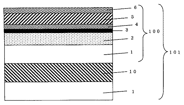
以下、本発明の実施の形態について説明する。図1は、本発明の反射防止フィルムの一実施形態の断面図である。
図1において、本発明の反射防止フィルム100は、透明基材フィルム1上に、ハードコート層2、第一プライマー層3、第2プライマー層4、反射防止層5が順次積層されている。さらに反射防止層5上に防汚層6が積層されている。
透明基材フィルム1としては、偏光子を吸着させたポリビニルアルコールフィルムの表面保護層となる基材を適用する。透明基材フィルム1としては、本発明の効果を奏すれば、材料に限りはないが、一般的に、トリアセチルセルロースなどのセルロースアセテート系樹脂などが挙げられる。更に、これらを使用する場合、その酢化度は問わない。透明基材フィルム1の厚さは、目的の用途に応じて、適宜選択すればよく、通常25〜300μm程度のものを使用する。また、この透明基材フィルム1には、可塑剤や紫外線吸収剤、劣化防止剤等の添加物が含まれても良い。
Embodiments of the present invention will be described below. FIG. 1 is a cross-sectional view of an embodiment of the antireflection film of the present invention.
In FIG. 1, an
As the
透明基材フィルム1上に、反射防止層5の機械強度を十分に発揮させるためのハードコート層2を設けてもよい。このハードコート層2としては、電離線や紫外線硬化型の樹脂あるいは、熱硬化性樹脂が使用され、紫外線硬化型のアクリル酸エステル類、アクリルアミド類、メタクリル酸エステル類、メタクリルアミド等のアクリル系樹脂や有機珪素系樹脂やポリシロキサン樹脂が最適である。これらの材料の中には、硬化性を向上させるために、重合開始剤を添加してもよい。ハードコート層2の厚みとしては、物理膜厚0.5μm以上、好ましくは、3〜20μmである。また、ハードコート層2には、平均粒子0.01〜3μmの透明微粒子を分散させて、防眩処理を施しても良い。
A
透明基材フィルム1にハードコート層2を設けたのち、アルカリ鹸化処理が施されていることが好ましい。特に、トリアセチルセルロース基材においては、エステル基を加水分解し、水酸基を付与するアルカリ鹸化処理が好ましく、これにより、後工程である、ポリビニルアルコール層10との貼り合わせの密着性が著しく向上する。また、鹸化処理は液中の処理であるため、侵食・浸透性が高く、ハードコート層2においても、その後の層との密着性が高い。
It is preferable that after the
また、鹸化工程の後、ハードコート層2側には、さらに、表面処理を施しても良い。このとき、表面処理方法としては、コロナ放電処理や電子ビーム処理、火炎処理、グロー放電処理、大気圧プラズマ処理等の処理が挙げられる。本発明では、低温プラズマ表面処理を施すのがとくに好ましい。
Further, after the saponification step, surface treatment may be further performed on the
この後、ハードコート層2に、第一プライマー層3、第二プライマー層4を順番に設ける。プライマー層の材料としては、例えば、シリコン、ニッケル、クロム、錫、金、銀、白金、亜鉛、チタン、タングステン、ジルコニウム、パラジウム等の金属、あるいは、これら金属の2種類以上からなる合金、これらの酸化物、弗化物、硫化物、窒化物などの金属化合物が挙げられ、これは混合物であってもよい。このとき、第一プライマー層3と第二プライマー層4は異なる組成の膜を形成することが望ましい。
Thereafter, the
第一プライマー層3は、微小な凹凸表面を形成することにより、その後に積層させる成長方向を不規則な方向に形成させるための層である。基材表面に、極微量の粒子が付いてあれば良く、その膜は、粒子状や島状で構わない。その厚みは、物理膜厚で、5nm以下程度であり、更に、2nm以下であることが好ましい。また、その後の膜を不規則性に成膜するために、ジグザグ構造や波上構造に薄膜を形成しても良いが、透明性に影響を及ぼさない程度の膜厚と、材料を選択する必要がある。このような層の成膜条件としては、例えば成膜時間が極めて短いスパッタリングが挙げられ、装置条件によって異なるが数秒程度の照射が挙げられる。
第一プライマー層3は、アルミナ、シリカ、酸化ニオブ、酸化チタンなどから形成されることが好ましい。
The
The
第二プライマー層4は、密着性を向上させるために用いる。その厚みは、基材の透明性を損なわない程度あればよく、好ましくは、物理膜厚で、10nm以下、例えば1〜10nm程度であり、第一プライマー層3よりも厚い方が良い。
第二プライマー層4は、例えばSiOのような結合手が一本余った状態のもの、あるいは、市販のシランカップリング剤などを使用してもよい。
The
For the
これらのプライマー層は、スパッタリング法、反応性スパッタリング法、蒸着法、イオンプレーティング法、化学蒸着(CVD)法などのドライコーティング方法を用いることが好ましい。スパッタリング法がとくに好ましい。 These primer layers are preferably formed by a dry coating method such as a sputtering method, a reactive sputtering method, a vapor deposition method, an ion plating method, or a chemical vapor deposition (CVD) method. Sputtering is particularly preferred.
反射防止層5としては、波長550nmにおける光の屈折率が1.6未満でかつ波長550nmにおける光の消衰係数が0.5以下の低屈折率透明薄膜層からなるものや、波長550nmにおける光の屈折率が1.9以上の高屈折率透明薄膜層、光の屈折率1.6未満の低屈折率透明薄膜層、光の屈折率1.6〜1.9程度の中屈折率透明薄膜層などの屈折率の異なる光学薄膜を複数積層した物などが挙げられる。例えば、高屈折率透明薄膜層、低屈折率透明薄膜層を交互に積層したものとして、基材側より順番に、高屈折率透明薄膜層、低屈折率透明薄膜層、高屈折率透明薄膜層、低屈折率透明薄膜層と構成したものが挙げられる。
The
高屈折率透明薄膜層の材料としては、インジウム、錫、チタン、シリコン、亜鉛、ジルコニウム、ニオブ、マグネシウム、ビスマス、セリウム、タンタル、アルミニウム、ゲルマニウム、カリウム、アンチモン、ネオジウム、ランタン、トリウム、ハフニウム無等の金属、あるいは、これら金属の2種類以上からなる合金、これらの酸化物、弗化物、硫化物、窒化物などが挙げられる。具体的には、酸化チタン、酸化ニオブ、酸化ジルコニウム、酸化タンタル、酸化亜鉛、酸化インジウム、酸化セリウム等が挙げられるがこれに限られるものではない。また、複数積層する場合、必ずしも同じ材料を選択する必要なく、目的にあわせて、適宜選択すればよい。 High refractive index transparent thin film layer materials include indium, tin, titanium, silicon, zinc, zirconium, niobium, magnesium, bismuth, cerium, tantalum, aluminum, germanium, potassium, antimony, neodymium, lanthanum, thorium, hafnium, etc. Or an alloy composed of two or more of these metals, oxides thereof, fluorides, sulfides, nitrides, and the like. Specific examples include titanium oxide, niobium oxide, zirconium oxide, tantalum oxide, zinc oxide, indium oxide, and cerium oxide, but are not limited thereto. Moreover, when laminating | stacking two or more, it is not necessary to select the same material necessarily, According to the objective, it should just select suitably.
低屈折率透明薄膜層の材料としては、例えば、酸化シリコン、窒化チタン、弗化マグネシウム、弗化バリウム、弗化カルシウム、弗化ハフニウム、弗化ランタン等の材料が、挙げられるがこれに限られるものでなく、更に、複数積層する場合、必ずしも同じ材料を選択する必要なく、目的にあわせて、適宜選択すればよい。 Examples of the material for the low refractive index transparent thin film layer include, but are not limited to, materials such as silicon oxide, titanium nitride, magnesium fluoride, barium fluoride, calcium fluoride, hafnium fluoride, and lanthanum fluoride. In addition, when a plurality of layers are stacked, it is not always necessary to select the same material, and it may be appropriately selected according to the purpose.
中屈折率透明薄膜層としては、例えば、酸化アルミニウム、弗化セリウムなどが挙げられる。 Examples of the medium refractive index transparent thin film layer include aluminum oxide and cerium fluoride.
これらの光学薄膜層からなる反射防止層5は、スパッタリング法、反応性スパッタリング法、蒸着法、イオンプレーティング法、化学蒸着(CVD)法などのドライコーティング方法で形成できる。膜厚均一性が高く、ピンホール等の欠陥が少ないため、より視認性に優れた薄膜の形成が可能であり、緻密な膜の形成が可能であることから、耐擦傷性などの機械特性に優れた薄膜の形成が可能であることからスパッタリング法を用いることが好ましい。中でも、より高い成膜速度と高い放電安定性により高生産性を得ることができることから、中周波領域の電圧印加により成膜を行うデュアル・マグネトロン・スパッタリング(DMS)法が最適である。
The
必要に応じて、反射防止層5の上、最表面層に防汚層6を設けても良い。防汚層6は、反応性官能基と結合している珪素原子を2つ以上有するフッ素含有珪素化合物から得られた層である。本発明における反応性官能基とは、反射防止層の最上層と反応し、結合しうる基を意味する。また、フッ素含有珪素化合物の反応性官能基同士を反応させることにより形成される層である。これにより、表面に汚れが付きにくく、更に、汚れが付いた場合でも拭き取り性能を上げることができる。
If necessary, an antifouling layer 6 may be provided on the outermost surface layer on the
ところで、これらの反射防止フィルムの水蒸気透過度を測定する際には、基材や機能層の材質、厚み、更には温湿度の影響を受けて変化する。透湿率の温度依存性はアレニウス式で表される。
P=P0e−E/RT
P:透湿率(単位厚さ、単位水蒸気圧差あたりの水蒸気透過度)
P0:絶対零度の透湿率
E:透湿率の活性化エネルギー
R:気体定数
T:絶対温度
By the way, when measuring the water vapor transmission rate of these antireflection films, it changes under the influence of the material and thickness of the base material and the functional layer, and further the temperature and humidity. The temperature dependence of moisture permeability is expressed by the Arrhenius equation.
P = P0e-E / RT
P: moisture permeability (water vapor permeability per unit thickness, unit water vapor pressure difference)
P0: Moisture permeability of absolute zero E: Activation energy of moisture permeability
R: Gas constant
T: Absolute temperature
偏光板の表面保護膜として汎用されているトリアセチルセルロースフィルムの場合、厚さ100μmの水蒸気透過度は温度25℃相対湿度90%で120〜160g/m2/day、温度40℃相対湿度90%で380g/m2/dayとなる。この基材上に、様々な層を積層することで、水蒸気は、フィルムを透過しにくくなる。特に、優れた機械特性を有した緻密な膜により形成された反射防止層の水蒸気透過度は、ほぼゼロに近く、優れた水蒸気バリア性能を示す。 In the case of a triacetyl cellulose film that is widely used as a surface protective film for polarizing plates, the water vapor permeability with a thickness of 100 μm is 120 to 160 g / m 2 / day at a temperature of 25 ° C. and a relative humidity of 90%, and a temperature of 40 ° C. and a relative humidity of 90%. 380 g / m 2 / day. By laminating various layers on this substrate, water vapor hardly penetrates the film. In particular, the water vapor permeability of the antireflection layer formed of a dense film having excellent mechanical properties is almost zero, and exhibits excellent water vapor barrier performance.
反射防止層5は複数の無機化合物を積層させているが、少なくともどれか1層が優れた水蒸気バリア性があると、そのフィルム全体の水蒸気バリア性能は高くなる。どれか一層フィルム内部からの水分の抜けは少なくなるため、全体の水蒸気透過度が速くなるように性能を改善する必要がある。
The
すなわち、本発明においては、反射防止層5の水蒸気透過度を調整するとともに、ハードコート層2と反射防止層5との間に、薄膜成長方向を不規則にする第一プライマー層3、密着性を付与する第二プライマー層4を挟む事で、例えばスパッタリング法の大きな利点である緻密な膜の形成が可能な特徴を有したまま、緻密な膜ゆえの特徴であった低い透湿性を改善し、適度な透湿性かつ密着性が良い高耐久性能を有した反射防止膜の形成が可能とした。
That is, in the present invention, the water vapor permeability of the
本発明の反射防止フィルムは、温度40℃、相対湿度90%RHにおける水蒸気透過度が、20g/m2/day以上が好ましく、40〜250g/m2/dayがさらに好ましい。
The antireflection film of the present invention, the temperature 40 ° C., water vapor permeability at a relative humidity of 90% RH is preferably at least 20g /
次に、図2を参照して、反射防止フィルム100を有する偏光板101について説明する。この偏光板101は、上記反射防止フィルム100と、ヨウ素により染色したポリビニルアルコールフィルム10、反対面の透明基材フィルム1と同じ材質のフィルム1、をこの順に積層し、貼り合わせることにより作成することができる。なお、反射防止フィルム以外の層構成については、これに限らず、公知の技術を採用できる。
Next, the polarizing plate 101 having the
以下、本発明を実施例および比較例によりさらに説明するが、本発明は下記例に限定されるものではない。 EXAMPLES Hereinafter, although an Example and a comparative example further demonstrate this invention, this invention is not limited to the following example.
[実施例1]
透明基材フィルム1に厚さ80μmのトリアセチルセルロースを用い、紫外線硬化型アクリル系樹脂を塗布し、乾燥・紫外線硬化させて5μmのハードコート層2を設けた後、40℃の1.5N−NaOH溶液にフィルムを2分間浸漬し、水洗し乾燥させた。
[Example 1]
The
鹸化処理を施したハードコート層2上に、グロープラズマ処理を施し、第一プライマー層3として、Al2O3膜を、スパッタリング法により成膜した。成膜は、電力7kW、アルゴンガス流量1300sccmの条件で2秒間成膜した。第二プライマー層4として、SiO層を、電力2.0kW、アルゴンガス流量300sccmの条件で、光学膜厚6nm成膜した。その後、反射防止層5として、成膜順に、TiO2/SiO2/TiO2/SiO2の4層設けた。TiO2の成膜は、電力2.5kW、アルゴンガス流量300sccm、酸素ガス流量40sccm、SiO2の成膜は、電力2.0kW、アルゴンガス流量300sccm、酸素ガス流量20sccm、それぞれ成膜中の真空層内の圧力は、0.5Paで行った。
A glow plasma treatment was performed on the saponified
反射防止層各層の光学膜厚は、光学式の膜厚モニターにより、光量値を監視し、反射防止層の光学膜厚が、高屈折率透明薄膜層(TiO2)、低屈折率透明薄膜層(SiO2)、高屈折率透明薄膜層(TiO2)、低屈折率透明薄膜層(SiO2)として、それぞれ60nm/44nm/105nm/145nmとなるように成膜時間を設定した。 The optical film thickness of each antireflection layer is monitored by an optical film thickness monitor, and the optical film thickness of the antireflection layer is a high refractive index transparent thin film layer (TiO 2 ) or a low refractive index transparent thin film layer. The film formation time was set to 60 nm / 44 nm / 105 nm / 145 nm for (SiO 2 ), high refractive index transparent thin film layer (TiO 2 ), and low refractive index transparent thin film layer (SiO 2 ), respectively.
このように、作成した反射防止フィルム100の裏面に、図2に示したように、ヨウ素により染色した厚さ25μmのポリビニルアルコールフィルム10、厚さ80μmのトリアセチルセルロース1を貼り合わせ、反射防止機能付きの偏光板101を作成した。
Thus, as shown in FIG. 2, the 25 μm-thick
[実施例2]
第一プライマー層3として、SiO2膜を用いた以外は、実施例1と同じ条件で反射防止機能付きの偏光板を形成した。
[Example 2]
A polarizing plate with an antireflection function was formed under the same conditions as in Example 1 except that an SiO 2 film was used as the
[比較例1]
ハードコート層に鹸化処理を施した後、直接、反射防止層を設けた以外は、実施例1と同様の条件にて、反射防止機能付きの偏光板を作成した。
[Comparative Example 1]
A polarizing plate with an antireflection function was prepared under the same conditions as in Example 1 except that the hard coat layer was saponified and then directly provided with an antireflection layer.
[比較例2]
プラズマ処理を施した後、第二プライマー層を設けずに第一プライマー層のみ設けた以外は、実施例1同様の条件にて、反射防止層を形成した偏光板を作成した。
[Comparative Example 2]
After the plasma treatment, a polarizing plate having an antireflection layer was prepared under the same conditions as in Example 1 except that only the first primer layer was provided without providing the second primer layer.
[比較例3]
プラズマ処理を施した後、第一プライマー層を設けずに第二プライマー層のみ設けた以外は、実施例1同様の条件にて、反射防止層を形成した偏光板を作成した。
[Comparative Example 3]
After performing the plasma treatment, a polarizing plate having an antireflection layer was prepared under the same conditions as in Example 1 except that only the second primer layer was provided without providing the first primer layer.
[比較例4]
トリアセチルセルロースフィルムにハードコート層を設けた後、反射防止層は設けずに、偏光板と貼り合わせた。
[Comparative Example 4]
After providing the hard coat layer on the triacetyl cellulose film, it was bonded to the polarizing plate without providing the antireflection layer.
[評価]
実施例、比較例で得られたサンプルを以下の方法で評価した。結果は表1に示す。
[Evaluation]
Samples obtained in Examples and Comparative Examples were evaluated by the following methods. The results are shown in Table 1.
(1)スチールウール擦傷試験
スチールウール#0000を擦傷試験機に固定し、500gfの荷重をかけて、10往復の擦傷試験を各サンプルの反射防止層に対して行い、サンプルの磨耗状態(傷本数)を目視で観測した。
(1) Steel Wool Abrasion Test Steel wool # 0000 is fixed to an abrasion tester, a load of 500 gf is applied, and a 10-reciprocal abrasion test is performed on the antireflection layer of each sample. ) Was observed visually.
(2)耐熱性試験
実施例および比較例で作成した偏光板を、粘着フィルムを介して、ガラスに貼り付け、温度95℃のドライ環境の条件下に設定した恒温恒湿槽内に保持し、耐久性の評価を行った。セルロースフィルムの加水分解などの劣化の有無を、目視にて及び酢酸臭の確認、及び赤外分光測定におけるカルボニル基の吸収スペクトルの変化により判断した。
(2) Heat resistance test The polarizing plate created in the Examples and Comparative Examples was attached to glass via an adhesive film, and held in a constant temperature and humidity chamber set at a dry environment temperature of 95 ° C. Durability was evaluated. The presence or absence of degradation such as hydrolysis of the cellulose film was judged by visual observation, confirmation of acetic acid odor, and change in absorption spectrum of carbonyl group in infrared spectroscopic measurement.
(3)耐湿熱性試験
実施例および比較例で作成した偏光板を、粘着フィルムを介して、ガラスに貼り付け、温度60℃、相対湿度95%のドライ環境の条件下に設定した恒温恒湿槽内に保持し、耐久性の評価を行った。セルロースフィルムの加水分解などの劣化の有無を、目視にて及び酢酸臭の確認、及び赤外分光測定におけるカルボニル基の吸収スペクトルの変化により判断した。
(3) Moisture and heat resistance test The polarizing plate created in the examples and comparative examples was attached to glass via an adhesive film, and the temperature and humidity chamber was set under conditions of a dry environment at a temperature of 60 ° C and a relative humidity of 95%. The durability was evaluated. The presence or absence of degradation such as hydrolysis of the cellulose film was judged by visual observation, confirmation of acetic acid odor, and change in absorption spectrum of carbonyl group in infrared spectroscopic measurement.
(4)水蒸気透過度
それぞれ、偏光板を貼り付ける前の、反射防止フィルムにおいて、温度40℃、相対湿度90%Rhの環境下における、水蒸気透過度を測定した。水蒸気透過度の測定は、JIS Z0208に順ずる方法を用いて測定した。
(4) Water vapor transmission rate Each of the water vapor transmission rates in an environment of a temperature of 40 ° C. and a relative humidity of 90% Rh was measured in the antireflection film before the polarizing plate was attached. The water vapor permeability was measured using a method according to JIS Z0208.
実施例1から2で作成した反射防止フィルムを備えた偏光板においては、耐擦傷性性能が良好なことから、密着性が良く、さらに、耐熱性および耐湿熱性において、1000時間以上偏光板や偏光板の保護フィルムに変質のない優れた耐久性を有していることが確認できる。一方、比較例1の第一プライマー層のみでは、密着性が弱いことが、比較例2の第二プライマー層のみでは、密着性は良いものの、耐熱および耐湿熱試験、特に耐熱試験においては、250時間程度で加水分解反応が起こっていることが確認できた。 In the polarizing plate provided with the antireflection film prepared in Examples 1 and 2, since the scratch resistance performance is good, the adhesiveness is good. Further, in the heat resistance and moist heat resistance, the polarizing plate and the polarization are not less than 1000 hours. It can be confirmed that the protective film of the plate has excellent durability without deterioration. On the other hand, the adhesion of the first primer layer of Comparative Example 1 is weak, but the adhesion of the second primer layer of Comparative Example 2 is good. It was confirmed that hydrolysis reaction occurred in about time.
本発明の反射防止フィルムおよび偏光板は、LCDやCRT、プラズマデイスプレイパネル等の光学表示装置に有用である。 The antireflection film and polarizing plate of the present invention are useful for optical display devices such as LCDs, CRTs, and plasma display panels.
1 透明基材フィルム
2 ハードコート層
3 第一プライマー層
4 第二プライマー層
5 反射防止層
6 防汚層
10 偏光膜(ポリビニルアルコール)
100 本発明により作成された反射防止フィルム
101 本発明により作成された反射防止フィルムを有する偏光板
DESCRIPTION OF
100 Antireflective film 101 made by the present invention 101 Polarizing plate having an antireflective film made by the present invention
Claims (10)
該2層以上のプライマー層が、前記ハードコート層と接する第一プライマー層と前記反射防止層と接する第二プライマー層とを有し、該第一プライマー層および該第二プライマー層が、金属あるいは金属化合物単体もしくは混合物よりなり、
該第一プライマー層および該第二プライマー層が、異なる組成であり、
かつ、前記第二プライマー層の膜厚が10nm以下であり、かつ、前記第一プライマー層の膜厚が前記第二プライマー層の膜厚よりも薄い
ことを特徴とする反射防止フィルム。 An antireflection film in which a hard coat layer, two or more primer layers, and an antireflection layer are sequentially laminated on a transparent substrate film,
The two or more primer layers have a first primer layer in contact with the hard coat layer and a second primer layer in contact with the antireflection layer, and the first primer layer and the second primer layer are made of metal or It consists of a single metal compound or a mixture,
It said first primer layer and said second primer layer, Ri different composition der,
An antireflection film, wherein the second primer layer has a thickness of 10 nm or less, and the first primer layer has a thickness smaller than that of the second primer layer. .
前記反射防止層と接する第二プライマー層と前記第一プライマー層の組成が異なる、
ことを特徴とする請求項1〜3のいずれかに記載の反射防止フィルム。 The first primer layer in contact with the hard coat layer has fine irregularities on the surface,
The composition of the second primer layer in contact with the antireflection layer and the first primer layer are different.
The antireflection film according to any one of claims 1 to 3.
Priority Applications (1)
| Application Number | Priority Date | Filing Date | Title |
|---|---|---|---|
| JP2007075218A JP4873164B2 (en) | 2007-03-22 | 2007-03-22 | Antireflection film and polarizing plate |
Applications Claiming Priority (1)
| Application Number | Priority Date | Filing Date | Title |
|---|---|---|---|
| JP2007075218A JP4873164B2 (en) | 2007-03-22 | 2007-03-22 | Antireflection film and polarizing plate |
Publications (2)
| Publication Number | Publication Date |
|---|---|
| JP2008233667A JP2008233667A (en) | 2008-10-02 |
| JP4873164B2 true JP4873164B2 (en) | 2012-02-08 |
Family
ID=39906497
Family Applications (1)
| Application Number | Title | Priority Date | Filing Date |
|---|---|---|---|
| JP2007075218A Expired - Fee Related JP4873164B2 (en) | 2007-03-22 | 2007-03-22 | Antireflection film and polarizing plate |
Country Status (1)
| Country | Link |
|---|---|
| JP (1) | JP4873164B2 (en) |
Families Citing this family (10)
| Publication number | Priority date | Publication date | Assignee | Title |
|---|---|---|---|---|
| EP2378374B1 (en) | 2010-04-01 | 2019-09-25 | Ricoh Company, Ltd. | Powder container, powder supply assembly, and image forming apparatus |
| CN106646984A (en) * | 2015-07-22 | 2017-05-10 | 琦芯科技股份有限公司 | Macromolecular dispersed liquid crystal light-dimming structure |
| JP6096847B2 (en) * | 2015-08-07 | 2017-03-15 | ▲き▼芯科技股▲ふん▼有限公司 | Polymer dispersed liquid crystal dimming configuration |
| TWI744339B (en) * | 2016-06-17 | 2021-11-01 | 日商日東電工股份有限公司 | Anti-reflection film and manufacturing method thereof, and polarizing plate with anti-reflection layer |
| JP6774383B2 (en) | 2016-06-17 | 2020-10-21 | 日東電工株式会社 | Antireflection film and its manufacturing method, and polarizing plate with antireflection layer |
| KR102602238B1 (en) * | 2016-08-29 | 2023-11-15 | 삼성디스플레이 주식회사 | Array substrate, display panel having the same and method of manufacturing the same |
| KR101963005B1 (en) | 2016-10-31 | 2019-03-27 | 삼성에스디아이 주식회사 | Polarizing plate and liquid crystal display apparatus comprising the same |
| CN114761834B (en) * | 2019-11-26 | 2023-05-30 | 日东电工株式会社 | Antireflection film, method for producing the same, and image display device |
| CN114249546B (en) * | 2021-12-14 | 2023-11-28 | 佛山华国光学器材有限公司 | Carbon film-plated infrared chalcogenide glass lens and preparation method and application thereof |
| CN115343787B (en) * | 2022-06-27 | 2024-05-28 | 四川虹基光玻新材料科技有限公司 | AR film and preparation method and application thereof |
Family Cites Families (8)
| Publication number | Priority date | Publication date | Assignee | Title |
|---|---|---|---|---|
| JPH07329244A (en) * | 1994-06-13 | 1995-12-19 | Sumitomo Metal Ind Ltd | Polyolefin resin coated steel material |
| JP3375793B2 (en) * | 1994-07-29 | 2003-02-10 | Hoya株式会社 | Plastic lens with hard coat layer |
| JPH10282685A (en) * | 1997-04-09 | 1998-10-23 | Brother Ind Ltd | Photosensitive recording medium and its production |
| JP3027955B2 (en) * | 1997-05-02 | 2000-04-04 | 富士ゼロックス株式会社 | Heating member, method for producing the same, and primer composition used therefor |
| JP2000338303A (en) * | 1999-05-27 | 2000-12-08 | Dainippon Printing Co Ltd | Antireflection film |
| JP3825327B2 (en) * | 2002-01-22 | 2006-09-27 | バンドー化学株式会社 | Decorative sheet for wood board edge |
| JP2004345223A (en) * | 2003-05-22 | 2004-12-09 | Dainippon Printing Co Ltd | Functional optical film and image display |
| JP2005017707A (en) * | 2003-06-26 | 2005-01-20 | Nitto Denko Corp | Antireflection film, polarizing plate, optical element, and image display device |
-
2007
- 2007-03-22 JP JP2007075218A patent/JP4873164B2/en not_active Expired - Fee Related
Also Published As
| Publication number | Publication date |
|---|---|
| JP2008233667A (en) | 2008-10-02 |
Similar Documents
| Publication | Publication Date | Title |
|---|---|---|
| JP5262066B2 (en) | Manufacturing method of antireflection film and manufacturing method of polarizing plate including the same | |
| JP4873164B2 (en) | Antireflection film and polarizing plate | |
| JP5076729B2 (en) | Antireflection film and polarizing plate using the same | |
| JP5066989B2 (en) | Method for producing antireflection film | |
| KR102413741B1 (en) | Antireflection film, manufacturing method thereof, and polarizing plate with antireflection layer | |
| CN111183373B (en) | Antireflection film, method for producing same, and polarizing plate with antireflection layer | |
| WO2017217526A1 (en) | Reflection preventing film and method for manufacturing same, and reflection preventing layer-attached polarization plate | |
| JP2010191144A (en) | Antireflection film | |
| JP5369494B2 (en) | Antireflection film and polarizing plate having antireflection film | |
| JP2006327098A (en) | Transparent film and its manufacturing method | |
| TWI657929B (en) | Laminate, transparent conductive laminate, and touch panel | |
| JP2008268418A (en) | Reflection preventing film | |
| JP2007206146A (en) | Antireflection film, method of manufacturing the same and display equipped with the antireflection film | |
| JP2009075325A (en) | Antireflection film | |
| JP2010092003A (en) | Antireflection film | |
| KR20240014563A (en) | Optical laminate, article and image display device | |
| JP2009075417A (en) | Antireflection film, and polarizing plate using the same | |
| JP2009222851A (en) | Conductive antireflection film | |
| JP2002243902A (en) | Antireflection film | |
| JP7420700B2 (en) | Optical laminates and display devices | |
| WO2022080137A1 (en) | Polarizing plate provided with antireflective layer, and image display device | |
| JP7213323B2 (en) | optical laminate, article | |
| WO2023054420A1 (en) | Optical laminate and anti-reflection film | |
| JP2022179511A (en) | Optical laminate and display | |
| KR20230024434A (en) | optical stacks, articles |
Legal Events
| Date | Code | Title | Description |
|---|---|---|---|
| A621 | Written request for application examination |
Free format text: JAPANESE INTERMEDIATE CODE: A621 Effective date: 20100223 |
|
| A521 | Written amendment |
Free format text: JAPANESE INTERMEDIATE CODE: A523 Effective date: 20110223 |
|
| A977 | Report on retrieval |
Free format text: JAPANESE INTERMEDIATE CODE: A971007 Effective date: 20110810 |
|
| A131 | Notification of reasons for refusal |
Free format text: JAPANESE INTERMEDIATE CODE: A131 Effective date: 20110818 |
|
| A521 | Written amendment |
Free format text: JAPANESE INTERMEDIATE CODE: A523 Effective date: 20111007 |
|
| TRDD | Decision of grant or rejection written | ||
| A01 | Written decision to grant a patent or to grant a registration (utility model) |
Free format text: JAPANESE INTERMEDIATE CODE: A01 Effective date: 20111026 |
|
| A01 | Written decision to grant a patent or to grant a registration (utility model) |
Free format text: JAPANESE INTERMEDIATE CODE: A01 |
|
| A61 | First payment of annual fees (during grant procedure) |
Free format text: JAPANESE INTERMEDIATE CODE: A61 Effective date: 20111108 |
|
| FPAY | Renewal fee payment (event date is renewal date of database) |
Free format text: PAYMENT UNTIL: 20141202 Year of fee payment: 3 |
|
| R150 | Certificate of patent or registration of utility model |
Free format text: JAPANESE INTERMEDIATE CODE: R150 |
|
| LAPS | Cancellation because of no payment of annual fees |