JP4871237B2 - Pants-type absorbent article - Google Patents

Pants-type absorbent article Download PDF

Info

Publication number
JP4871237B2
JP4871237B2 JP2007246863A JP2007246863A JP4871237B2 JP 4871237 B2 JP4871237 B2 JP 4871237B2 JP 2007246863 A JP2007246863 A JP 2007246863A JP 2007246863 A JP2007246863 A JP 2007246863A JP 4871237 B2 JP4871237 B2 JP 4871237B2
Authority
JP
Japan
Prior art keywords
layer sheet
inner layer
composite stretchable
elastic member
packaging material
Prior art date
Legal status (The legal status is an assumption and is not a legal conclusion. Google has not performed a legal analysis and makes no representation as to the accuracy of the status listed.)
Active
Application number
JP2007246863A
Other languages
Japanese (ja)
Other versions
JP2009072532A (en
Inventor
賢司 小林
賢治 安藤
拓郎 梁島
Current Assignee (The listed assignees may be inaccurate. Google has not performed a legal analysis and makes no representation or warranty as to the accuracy of the list.)
Kao Corp
Original Assignee
Kao Corp
Priority date (The priority date is an assumption and is not a legal conclusion. Google has not performed a legal analysis and makes no representation as to the accuracy of the date listed.)
Filing date
Publication date
Application filed by Kao Corp filed Critical Kao Corp
Priority to JP2007246863A priority Critical patent/JP4871237B2/en
Publication of JP2009072532A publication Critical patent/JP2009072532A/en
Application granted granted Critical
Publication of JP4871237B2 publication Critical patent/JP4871237B2/en
Active legal-status Critical Current
Anticipated expiration legal-status Critical

Links

Images

Description

本発明は、パンツ型使い捨ておむつやパンツ型生理用ナプキン等のパンツ型吸収性物品に関する。   The present invention relates to a pants-type absorbent article such as a pants-type disposable diaper and a pants-type sanitary napkin.

従来より、吸収性コアを含む吸収性本体と該吸収性本体の非肌当接面側に接合された外包材とを備えたパンツ型使い捨ておむつにおいて、着用者へのフィット性を向上させること等を目的に、外包材のウエスト部にウエストギャザーを設けたものが知られている(例えば、下記特許文献1参照)。特許文献1記載のパンツ型使い捨ておむつにおいては、外包材は、外層シート、内層シート及び両シート間に配設された複数本の弾性部材から形成されており、ウエストギャザーは、ウエスト部において該弾性部材が外層シート及び内層シートに間欠的に接合されて形成されている。   Conventionally, in a pants-type disposable diaper comprising an absorbent main body including an absorbent core and an outer packaging material joined to the non-skin-contacting surface side of the absorbent main body, improving fit to the wearer, etc. For this purpose, there is known one in which a waist gather is provided in the waist portion of the outer packaging material (for example, see Patent Document 1 below). In the pants-type disposable diaper described in Patent Document 1, the outer packaging material is formed from an outer layer sheet, an inner layer sheet, and a plurality of elastic members disposed between the two sheets, and the waist gather is elastic at the waist portion. The member is formed by intermittently joining the outer layer sheet and the inner layer sheet.

特開2004−89403号公報JP 2004-89403 A

特許文献1記載のパンツ型使い捨ておむつのような、吸収性本体とその非肌当接面側に接合された外包材とを備えたパンツ型使い捨ておむつにおいては、吸収性本体の長手方向端部をシート(以下「押さえ付けシート」という)で覆い、押さえ付けシートを外包材に接合した構成を採用することが望ましい。その理由は、外包材に接合された押さえ付けシートによって、吸収性本体の長手方向両端部からの吸収性コアの吸収性ポリマーの漏れを防止するためである。   In a pants-type disposable diaper having an absorbent main body and an outer packaging material bonded to the non-skin contact surface side, such as a pants-type disposable diaper described in Patent Document 1, a longitudinal end portion of the absorbent main body is provided. It is desirable to employ a configuration in which the sheet is covered with a sheet (hereinafter referred to as “pressing sheet”) and the pressing sheet is joined to the outer packaging material. The reason is to prevent leakage of the absorbent polymer of the absorbent core from both longitudinal ends of the absorbent main body by the pressing sheet bonded to the outer packaging material.

押さえ付けシートと外包材とを別体で構成した場合には、構成がシンプルであるという利点があるが、その反面、製造時において、押さえ付けシートと外包材との位置合わせの必要があり、製造が容易ではなく、また、外包材とは別体の押さえ付けシートでは、押さえ付けシートと外包材とを接合する接着剤を十分に塗工する必要があるため、ウエスト部が硬くなりやすく、良好なウエスト部の肌触りが得られにくい。   When the pressing sheet and the outer packaging material are configured separately, there is an advantage that the configuration is simple, but at the time of manufacturing, it is necessary to align the pressing sheet and the outer packaging material, It is not easy to manufacture, and in the pressing sheet separate from the outer packaging material, it is necessary to sufficiently apply an adhesive that joins the pressing sheet and the outer packaging material, so the waist part tends to become hard, It is difficult to obtain a good waist feel.

また、外包材において外層シート及び内層シートを吸収性本体側よりも延出するように構成し、延出した両シートの延出領域を吸収性本体側に折り返して、吸収性本体の長手方向端部を覆うことも考えられるが、このような構成では、外包材の長手方向端部からの通気性が低下する。
このような点は、パンツ型使い捨ておむつ以外のパンツ型吸収性物品においても同様である。
Further, in the outer packaging material, the outer layer sheet and the inner layer sheet are configured to extend from the absorbent main body side, the extended regions of both the extended sheets are folded back to the absorbent main body side, and the longitudinal end of the absorbent main body Although it is conceivable to cover the portion, in such a configuration, the air permeability from the longitudinal end portion of the outer packaging material is lowered.
The same applies to pants-type absorbent articles other than pants-type disposable diapers.

従って、本発明の目的は、吸収性コアを含む吸収性本体と吸収性本体の非肌当接面側に接合された外包材とを備えたパンツ型吸収性物品において、吸収性本体の長手方向端部をシートで覆った形態を採用した場合でも、製造が容易であると共に、外包材の長手方向端部からの通気性に優れたパンツ型吸収性物品を提供することにある。   Accordingly, an object of the present invention is to provide a pants-type absorbent article comprising an absorbent main body including an absorbent core and an outer packaging material bonded to the non-skin contact surface side of the absorbent main body. Even when a form in which the end portion is covered with a sheet is employed, it is an object of the present invention to provide a pant-type absorbent article that is easy to manufacture and excellent in air permeability from the end portion in the longitudinal direction of the outer packaging material.

本発明は、吸収性コアを含む吸収性本体と吸収性本体の非肌当接面側に接合された外包材とを備え、長手方向に腹側部、股下部及び背側部に区分されており、腹側部及び背側部の両側縁部同士が接合されて一対のサイドシール部、ウエスト開口部及び一対のレッグ開口部が形成されているパンツ型吸収性物品であって、外包材は、外面を形成する外層シート、吸収性本体側に位置する内層シート及び両シート間に配設された複数本の弾性部材から形成されており、外包材における外層シートの長手方向端部近傍には、複合伸縮部から形成された端部近傍ギャザーが設けられており、前記複合伸縮部は、外層シート及び内層シートが複合伸縮部の伸縮方向に間欠的で且つそれに直交する方向において間欠的又は連続的な接合部により互いに接合され、外層シート及び内層シートそれぞれが各々複数本の弾性部材に亘って連続して延びる複数本の襞を形成することにより構成されており、内層シートは、外層シートの長手方向端部よりも更に延出する長さを有し、外層シートよりも延出した延出領域が吸収性本体側に折り返されており、折り返された内層シートの延出領域によって、吸収性本体の長手方向端部における肌当接面側が覆われているパンツ型吸収性物品を提供することにより前記目的を達成したものである。   The present invention includes an absorbent main body including an absorbent core and an outer packaging material bonded to the non-skin contact surface side of the absorbent main body, and is divided into a ventral part, a crotch part, and a dorsal part in the longitudinal direction. A pants-type absorbent article in which a pair of side seal parts, a waist opening part, and a pair of leg opening parts are formed by joining both side edges of the abdominal part and the back part, The outer layer sheet forming the outer surface, the inner layer sheet located on the absorbent main body side, and a plurality of elastic members disposed between the two sheets, in the vicinity of the longitudinal end of the outer layer sheet in the outer packaging material An end vicinity gather formed from a composite stretchable part is provided, the composite stretchable part being intermittent or continuous in a direction in which the outer layer sheet and the inner layer sheet are intermittent in the direction of expansion and contraction of the composite stretchable part and perpendicular thereto. To each other by a typical joint Each of the outer layer sheet and the inner layer sheet is formed by forming a plurality of ridges that continuously extend over a plurality of elastic members, and the inner layer sheet is further formed in the longitudinal direction of the outer layer sheet. The extending region having an extending length and extending from the outer layer sheet is folded back to the absorbent main body side, and the extended region of the folded inner layer sheet is used at the longitudinal end portion of the absorbent main body. The object is achieved by providing a pants-type absorbent article having a skin contact surface side covered.

本発明のパンツ型吸収性物品によれば、吸収性コアを含む吸収性本体と吸収性本体の非肌当接面側に接合された外包材とを備えたパンツ型吸収性物品において、吸収性本体の長手方向端部をシートで覆った形態を採用した場合でも、製造が容易であると共に、外包材の長手方向端部からの通気性に優れている。   According to the pant-type absorbent article of the present invention, in the pant-type absorbent article comprising the absorbent main body including the absorbent core and the outer packaging material joined to the non-skin contact surface side of the absorbent main body, Even when a configuration in which the longitudinal end portion of the main body is covered with a sheet is adopted, the manufacturing is easy and the air permeability from the longitudinal end portion of the outer packaging material is excellent.

以下、本発明のパンツ型吸収性物品について、その好ましい一実施形態である第1実施形態に基づき図面を参照しながら説明する。
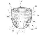
第1実施形態は、本発明のパンツ型吸収性物品をパンツ型使い捨ておむつに適用したもので、図1〜図4に示すように、吸収性コア34を含む吸収性本体3と吸収性本体3の非肌当接面側に接合された外包材2とを備え、長手方向に腹側部A、股下部C及び背側部Bに区分されており、腹側部A及び背側部Bの両側縁部同士が接合されて一対のサイドシール部11、ウエスト開口部12及び一対のレッグ開口部13が形成されているパンツ型使い捨ておむつである。
Hereinafter, the underpants type absorbent article of the present invention will be described with reference to the drawings based on the first embodiment which is a preferred embodiment thereof.
In the first embodiment, the pant-type absorbent article of the present invention is applied to a pants-type disposable diaper. As shown in FIGS. 1 to 4, the absorbent main body 3 including the absorbent core 34 and the absorbent main body 3. And the outer packaging material 2 joined to the non-skin contact surface side, and is divided in the longitudinal direction into an abdominal part A, a crotch part C, and a dorsal part B. A pants-type disposable diaper in which both side edges are joined to each other to form a pair of side seal portions 11, a waist opening portion 12, and a pair of leg opening portions 13.

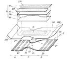
また、外包材2は、図1〜図5に示すように、外面を形成する外層シート21、吸収性本体3側に位置する内層シート22及び両シート21,22間に配設された複数本の弾性部材23,24,25,26から形成されている。外包材2における外層シート21の長手方向端部近傍には、複合伸縮部4(図10参照)から形成された端部近傍ギャザーが設けられている。第1実施形態における端部近傍ギャザーは、外包材2のウエスト開口部12近傍に設けられたウエストギャザーG2である   Moreover, as shown in FIGS. 1-5, the outer packaging material 2 has the outer layer sheet | seat 21 which forms an outer surface, the inner layer sheet | seat 22 located in the absorptive main body 3 side, and multiple sheets arrange | positioned between both sheets 21 and 22 These elastic members 23, 24, 25, and 26 are formed. Near the end in the longitudinal direction of the outer layer sheet 21 in the outer packaging material 2, an end vicinity gather formed from the composite stretchable part 4 (see FIG. 10) is provided. The edge vicinity gathers in 1st Embodiment are the waist gathers G2 provided in the waist opening part 12 vicinity of the outer packaging material 2. FIG.

詳述すると、第1実施形態の使い捨ておむつ1は、図1〜図4に示すように、液透過性の表面シート32、液不透過性又は撥水性の裏面シート33及び両シート32、33間に介在配置された液保持性の吸収性コア34を有する実質的に縦長の吸収性本体3と、吸収性本体3の裏面シート33側(非肌当接面側)に接合された外包材2とを備えている。吸収性本体3は、外包材2の腹側部Aから背側部Bに跨って配設されているが、吸収性本体3の長手方向端部は、外包材2の長手方向端部よりも長手方向内方に後退している。吸収性本体3は、接着剤、ヒートシール、超音波シール等による本体接合部15によって外包材2の内層シート22に接合されている。   Specifically, the disposable diaper 1 according to the first embodiment includes a liquid-permeable top sheet 32, a liquid-impermeable or water-repellent back sheet 33, and both sheets 32 and 33, as shown in FIGS. A substantially vertically long absorbent main body 3 having a liquid-retaining absorbent core 34 interposed between and the outer packaging material 2 joined to the back sheet 33 side (non-skin contact surface side) of the absorbent main body 3. And. The absorbent main body 3 is disposed across the ventral side A to the back side B of the outer packaging material 2, but the longitudinal end of the absorbent main body 3 is more than the longitudinal end of the outer packaging 2. Retreats inward in the longitudinal direction. The absorptive main body 3 is joined to the inner layer sheet 22 of the outer packaging material 2 by a main body joining portion 15 such as an adhesive, a heat seal, and an ultrasonic seal.

尚、使い捨ておむつ(吸収性物品)全体の長手方向、外包材2の長手方向及び吸収性本体3の長手方向は一致しており、従って、使い捨ておむつ(吸収性物品)全体の幅方向、外包材2の幅方向及び吸収性本体3の幅方向も一致している。また、「長手方向端部」とは、長手方向に延びる方向の端部であり、「側縁部」とは、幅方向に延びる方向の端部である。   In addition, the longitudinal direction of the whole disposable diaper (absorbent article), the longitudinal direction of the outer packaging material 2 and the longitudinal direction of the absorbent main body 3 are the same, and accordingly, the width direction of the entire disposable diaper (absorbent article), the outer packaging material. The width direction of 2 and the width direction of the absorptive main body 3 also correspond. The “longitudinal end portion” is an end portion in the direction extending in the longitudinal direction, and the “side edge portion” is an end portion in the direction extending in the width direction.

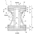
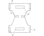
外包材2は、図2に示すように、その両側縁部が、長手方向中央部において内方に括れた砂時計形の形状を有しており、おむつの輪郭を画成している。外包材2は、その長手方向に、着用者の腹側に配される腹側部A、背側に配される背側部B及びその間に位置する股下部Cに区分される。腹側部A及び背側部Bは、それぞれ外包材2の長手方向前後部に相当し、股下部Cは外包材2の長手方向中央部に相当する。外包材2は、その腹側部Aの両側縁部と背側部Bの両側縁部とが互いに接合され、使い捨ておむつ1にはウエスト開口部12及び一対のレッグ開口部13が形成されている。この接合によって、使い捨ておむつ1の左右両側縁部には一対のサイドシール部11,11が形成され、パンツ型を形成している。この接合には、ヒートシール、高周波シール、超音波シール、接着剤等が用いられる。   As shown in FIG. 2, the outer wrapping material 2 has an hourglass shape in which both side edges are bound inward in the central portion in the longitudinal direction, thereby defining the outline of the diaper. The outer packaging material 2 is divided in the longitudinal direction into an abdominal side A disposed on the abdomen side of the wearer, a back side B disposed on the back side, and a crotch C positioned therebetween. The ventral side A and the back side B correspond to the longitudinal front and rear portions of the outer packaging material 2, respectively, and the crotch portion C corresponds to the longitudinal central portion of the outer packaging material 2. As for the outer packaging material 2, the both-sides edge part of the ventral | abdominal side part A and the both-sides edge part of the back side part B are mutually joined, and the waist opening part 12 and a pair of leg opening part 13 are formed in the disposable diaper 1. . By this joining, a pair of side seal parts 11 and 11 are formed on the left and right side edges of the disposable diaper 1 to form a pant-type. For this joining, a heat seal, a high frequency seal, an ultrasonic seal, an adhesive or the like is used.

表面シート32、裏面シート33及び吸収性コア34は、それぞれ矩形状で、一体化されて、縦長の吸収性本体3を形成している。表面シート32、裏面シート33及び吸収性コア34としては、それぞれ、従来からこの種のおむつに用いられているものと同様のものを用いることができる。例えば、吸収性コア34としては、吸収性ポリマーの粒子及び繊維材料から構成され、ティッシュペーパ(図示せず)によって被覆されているものを用いることができる。   The top sheet 32, the back sheet 33, and the absorbent core 34 are each rectangular and integrated to form a vertically long absorbent main body 3. As the surface sheet 32, the back surface sheet 33, and the absorptive core 34, the thing similar to what was conventionally used for this kind of diaper can be used, respectively. For example, the absorbent core 34 may be made of absorbent polymer particles and a fiber material and covered with tissue paper (not shown).

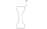
本実施形態における吸収性コア34は、図6に示すように、平面視で砂時計型である。吸収性コア34の平面視形状は、図6に示す形状に制限されず、矩形状等であっても良い。   As shown in FIG. 6, the absorbent core 34 in the present embodiment has an hourglass shape in plan view. The shape of the absorbent core 34 in plan view is not limited to the shape shown in FIG. 6 and may be a rectangular shape or the like.

吸収性本体3の長手方向両側部には、図2〜図4に示すように、液抵抗性又は撥水性で且つ通気性の素材から構成された側方カフス35、35が設けられている。尚、図5においては、側方カフス35の図示を省略している。各側方カフス35の自由端部近傍には、側方カフス弾性部材36が伸長状態で配されている。これにより、使い捨ておむつ1を着用させる際に、側方カフス弾性部材36が収縮することによって側方カフス35が起立して、吸収性本体3の幅方向への液の流出が阻止される。側方カフス35の形成用の側方カフス形成シート37は、図3及び図4に示すように、おむつの状態において、吸収性本体3の幅方向外側の所定幅の部分37Aが、裏面シート33の肌当接面側に巻き下げられ、吸収性コア34と裏面シート33との間に固定されている。   As shown in FIGS. 2 to 4, side cuffs 35 and 35 made of a liquid-resistant or water-repellent and breathable material are provided on both sides in the longitudinal direction of the absorbent main body 3. In FIG. 5, the illustration of the side cuffs 35 is omitted. In the vicinity of the free end of each side cuff 35, a side cuff elastic member 36 is disposed in an expanded state. Accordingly, when the disposable diaper 1 is worn, the side cuff elastic member 36 contracts, whereby the side cuff 35 stands up, and the outflow of the liquid in the width direction of the absorbent main body 3 is prevented. As shown in FIGS. 3 and 4, the side cuff forming sheet 37 for forming the side cuff 35 has a back surface sheet 33 with a portion 37 </ b> A having a predetermined width outside the width direction of the absorbent main body 3 in the diaper state. And is fixed between the absorbent core 34 and the back sheet 33.

外包材2は、図2、図3、図5及び図7に示すように、外層シート21、内層シート22及び両シート21,22間に配設された複数本の弾性部材23,24,25,26から形成されている。尚、図7は、外包材2を、仮想的に内層シート22を除去した状態で外層シート21の内面側から視た展開平面図である。外層シート21はおむつの外面を形成し、内層シート22は外層シート21の内面側(吸収性本体3側)に配されている。   As shown in FIGS. 2, 3, 5, and 7, the outer packaging material 2 includes an outer layer sheet 21, an inner layer sheet 22, and a plurality of elastic members 23, 24, 25 disposed between both sheets 21, 22. , 26. 7 is a developed plan view of the outer packaging material 2 viewed from the inner surface side of the outer layer sheet 21 in a state where the inner layer sheet 22 is virtually removed. The outer layer sheet 21 forms the outer surface of the diaper, and the inner layer sheet 22 is disposed on the inner surface side (the absorbent main body 3 side) of the outer layer sheet 21.

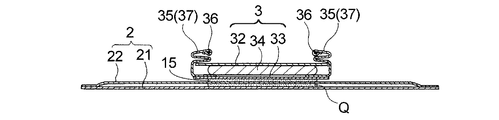
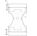
内層シート22は、図2、図3及び図5に示すように、外層シート21の長手方向端部よりも更に延出する長さを有し、外層シート21よりも延出した延出領域22Bが吸収性本体3側に折り返されている。折り返された内層シート22の延出領域22Bによって、吸収性本体3の長手方向端部における肌当接面側が覆われている。尚、内層シート22における延出領域22B以外の領域を非延出領域22Aという。
図5に示すように、内層シート22における折り返し部22Cと外層シート21の長手方向端部とは長手方向位置が略一致している。従って、外層シート21は、内層シート22の非延出領域22Aと同形である。
As shown in FIGS. 2, 3, and 5, the inner layer sheet 22 has a length that extends further than the end portion in the longitudinal direction of the outer layer sheet 21, and an extension region 22 </ b> B that extends beyond the outer layer sheet 21. Is folded back to the absorbent main body 3 side. The skin contact surface side of the end portion in the longitudinal direction of the absorbent main body 3 is covered with the extended region 22 </ b> B of the folded inner layer sheet 22. The region other than the extension region 22B in the inner layer sheet 22 is referred to as a non-extension region 22A.
As shown in FIG. 5, the position in the longitudinal direction of the folded portion 22 </ b> C of the inner layer sheet 22 and the longitudinal end of the outer layer sheet 21 are substantially the same. Accordingly, the outer layer sheet 21 has the same shape as the non-extending region 22 </ b> A of the inner layer sheet 22.

内層シート22の延出領域22Bは、吸収性本体3の長手方向両端部と重なる部分が、吸収性本体3の略全幅に亘って接着剤(図示せず)を介して接着されており、これにより、吸収性本体3の長手方向両端部が外包材2に固定される。
吸収性本体3の長手方向両端部における肌当接面側が、折り返された内層シート22の延出領域22Bによって覆われていることで、吸収性本体3の長手方向両端部が着用者に直接接触することを防止し、吸収性本体3の長手方向両端部からの吸収性コア34の吸収性ポリマーの漏れを防止することができる。
In the extension region 22B of the inner layer sheet 22, the portion overlapping the both ends in the longitudinal direction of the absorbent main body 3 is bonded via an adhesive (not shown) over substantially the entire width of the absorbent main body 3, Thus, both ends in the longitudinal direction of the absorbent main body 3 are fixed to the outer packaging material 2.
The skin contact surface side at both longitudinal ends of the absorbent main body 3 is covered with the extended region 22B of the folded inner layer sheet 22, so that both longitudinal ends of the absorbent main body 3 are in direct contact with the wearer. It is possible to prevent the leakage of the absorbent polymer of the absorbent core 34 from both longitudinal ends of the absorbent main body 3.

折り返された内層シート22の延出領域22Bと非延出領域22Aとの貼り合わせ面に用いるホットメルト型接着剤の塗工量は、複合伸縮部4の襞43(後述)の成形性や、完成後の使い捨ておむつの柔らかさ、通気性の観点から、少ないことが好ましい。同様に、塗工方法も襞の成形性に影響する。
複合伸縮部4の襞43は、見た目の美しさ、襞43の柔らかさ、クッション性及び素材本来の柔らかさを発現する点から、規則正しく形成されていることが好ましい。
The application amount of the hot melt adhesive used for the bonding surface of the extended region 22B and the non-extended region 22A of the folded inner layer sheet 22 is the formability of the ridge 43 (described later) of the composite stretchable part 4, From the viewpoint of softness and breathability of the disposable diaper after completion, it is preferable that the amount is small. Similarly, the coating method also affects the moldability of the wrinkles.
It is preferable that the ridges 43 of the composite stretchable part 4 are regularly formed from the viewpoint of appearance beauty, softness of the ridges 43, cushioning properties, and original softness of the material.

貼り合わせ用のホットメルト型接着剤の塗工量は、好ましくは0.5〜10g/m2、特に好ましくは0.5〜5g/m2、最も好ましくは0.5〜3g/m2である。塗工量が少なすぎると、接着強度を確保することが難しい。
塗工方法としては、従来から公知の塗工方法を用いることができるが、好適には、スパイラルノズルを用いた塗工方法が挙げられる。また、別の塗工方法としては、オメガノズル(ITW−DYNATEC社)、シュアラップノズル(NORDSON社)を用いた塗工方法も挙げられる。塗工パターンは通気性を阻害したり、素材が硬くなったりしないように、粗い方が好ましい。
更に、必要な部分だけにホットメルト型接着剤の塗工量を多くするような方法を採ることもできる。例えば、内層シート22の延出領域22Bの両側縁部に、ホットメルト型接着剤の塗工量を多くする方法がある。この方法は、スパイラルノズル、オメガノズル、シュアラップノズルや、カーテンスプレー、スロットコーター等を用いることにより、実施することができる。
The coating amount of the hot-melt adhesive for bonding is preferably 0.5 to 10 g / m 2 , particularly preferably 0.5 to 5 g / m 2 , and most preferably 0.5 to 3 g / m 2 . is there. If the coating amount is too small, it is difficult to ensure adhesive strength.
As a coating method, a conventionally known coating method can be used, and a coating method using a spiral nozzle is preferable. Moreover, as another coating method, the coating method using an omega nozzle (ITW-DYNATEC company) and a sure wrap nozzle (NORDSON company) is also mentioned. The coating pattern is preferably rough so as not to impair air permeability or harden the material.
Furthermore, it is possible to adopt a method that increases the amount of hot-melt adhesive applied to only the necessary portions. For example, there is a method of increasing the amount of hot-melt adhesive applied to both side edges of the extension region 22B of the inner layer sheet 22. This method can be carried out by using a spiral nozzle, an omega nozzle, a sure wrap nozzle, a curtain spray, a slot coater or the like.

外層シート21の内面(内層シート22との対向面)には、図8に示す塗工形状で、ホットメルト型接着剤等の接着剤Qが塗工されている。接着剤Qは、図8に示すように、サイドシール部11に対応する領域のほぼ全域、胴回り弾性部材23の非機能化領域51(後述)に対応する領域、レッグ弾性部材切断領域52(後述)に対応する領域に塗工されている。
一方、接着剤Qは、複合伸縮部4に対応する領域のほぼ全域及び股下部Cに対応する領域のほぼ全域には、塗工されていない。
The inner surface of the outer layer sheet 21 (the surface facing the inner layer sheet 22) is coated with an adhesive Q such as a hot melt adhesive in the coating shape shown in FIG. As shown in FIG. 8, the adhesive Q includes almost the entire region corresponding to the side seal portion 11, the region corresponding to the non-functionalized region 51 (described later) of the waistline elastic member 23, and the leg elastic member cutting region 52 (described later). ) Is applied to the area corresponding to.
On the other hand, the adhesive Q is not applied to almost the entire region corresponding to the composite stretchable part 4 and almost the entire region corresponding to the crotch C.

内層シート22における外層シート21との対向面には、図9に示す塗工形状で、ホットメルト型接着剤等の接着剤Qが塗工されている。接着剤Qは、図9に示すように、複合伸縮部4に対応する領域以外の領域のほぼ全域に塗工されている。
一方、接着剤Qは、外層シート21の内面と同様に、複合伸縮部4に対応する領域のほぼ全域には、塗工されていない。
On the surface of the inner layer sheet 22 facing the outer layer sheet 21, an adhesive Q such as a hot-melt adhesive is applied in the coating shape shown in FIG. As shown in FIG. 9, the adhesive Q is applied to almost the entire region other than the region corresponding to the composite stretchable portion 4.
On the other hand, the adhesive Q is not applied to almost the entire region corresponding to the composite stretchable portion 4, similarly to the inner surface of the outer layer sheet 21.

このように、内層シート22における外層シート21との対向面の接着剤Qの塗工形状は、外層シート21の内面における接着剤Qの塗工形状を包含している。そのため、外層シート21と内層シート22とを貼り合わせると、外層シート21の内面にも、内層シート22における外層シート21との対向面に塗工された接着剤Qが配され、結果的に、外層シート21の内面にも、内層シート22における外層シート21との対向面の塗工形状で、接着剤Qが塗工されることになる。   Thus, the coating shape of the adhesive Q on the surface facing the outer layer sheet 21 in the inner layer sheet 22 includes the coating shape of the adhesive Q on the inner surface of the outer layer sheet 21. Therefore, when the outer layer sheet 21 and the inner layer sheet 22 are bonded together, the adhesive Q applied to the inner surface of the outer layer sheet 21 on the surface facing the outer layer sheet 21 is also disposed on the inner layer sheet 21, The adhesive Q is also applied to the inner surface of the outer layer sheet 21 in the coating shape of the inner layer sheet 22 facing the outer layer sheet 21.

このとき、内層シート22に塗工した接着剤Qの塗工量と、外層シート21に塗工した接着剤Qの塗工量とを変えることができる。このように塗工量の変えることは、接着する目的に合わせて必要な接着保持力を確保するために、任意に設定することができ、非常に有効な方法である。また、塗工量だけでなく、塗工パターンも、同様に任意に設定することができる。接着剤Qは、1種類だけを用いるのではなく、複数の種類を任意に用いることもできる。   At this time, the coating amount of the adhesive Q applied to the inner layer sheet 22 and the coating amount of the adhesive Q applied to the outer layer sheet 21 can be changed. In this way, changing the coating amount can be arbitrarily set in order to ensure the necessary adhesion holding force in accordance with the purpose of bonding, and is a very effective method. Further, not only the coating amount but also the coating pattern can be set arbitrarily. As the adhesive Q, not only one type but also a plurality of types can be arbitrarily used.

本実施形態の使い捨ておむつ1においては、図3及び図4に示すように、腹側部A及び背側部Bのそれぞれにおける外層シート21と内層シート22との間は、サイドシール部11において、ヒートシール、高周波シール、超音波シール、接着剤等により互いに接合されている。   In the disposable diaper 1 of this embodiment, as shown in FIG.3 and FIG.4, between the outer-layer sheet | seat 21 and the inner-layer sheet | seat 22 in each of the ventral | abdominal part A and the back | dorsal part B, in the side seal part 11, They are joined to each other by heat sealing, high frequency sealing, ultrasonic sealing, adhesive, or the like.

また、外包材2の腹側部A及び背側部Bにおけるウエスト部FにはそれぞれウエストギャザーG2が設けられている。ウエスト部Fとは、ウエスト開口部12の周縁端から下方に30mm離間した位置までの領域をいい、例えば、腹側のウエスト開口部12の周縁端の位置と、背側のウエスト開口部12の周縁端の位置とがずれている場合(図示せず)においては、ずれて延出している領域がないものと仮定した上で、ウエスト部Fの範囲を定める。
ウエスト部Fについて詳述すると、腹側部A及び背側部Bそれぞれにおけるウエスト部Fには、ウエスト開口部12の周縁部に沿って、複数本のウエスト弾性部材24が配されている。そして、外層シート21、内層シート22及びウエスト弾性部材24を主体として複合伸縮部4(詳細は後述)が形成されており、この複合伸縮部4により、一対のサイドシール部11の間に亘って(ウエスト部Fの全周に亘って)ウエストギャザーG2が形成されている。
Further, waist gathers G <b> 2 are provided on the waist portions F in the ventral side portion A and the back side portion B of the outer packaging material 2. The waist portion F refers to a region from the peripheral edge of the waist opening 12 to a position spaced 30 mm downward, for example, the position of the peripheral edge of the abdominal waist opening 12 and the waist opening 12 on the back side. In the case where the position of the peripheral edge is shifted (not shown), the range of the waist portion F is determined on the assumption that there is no shifted and extended region.
The waist part F will be described in detail. A plurality of waist elastic members 24 are arranged along the peripheral edge of the waist opening 12 in the waist part F in each of the ventral part A and the back part B. A composite stretchable part 4 (details will be described later) is formed mainly of the outer layer sheet 21, the inner layer sheet 22 and the waist elastic member 24. The composite stretchable part 4 extends between the pair of side seal parts 11. A waist gather G2 is formed (over the entire circumference of the waist portion F).

外包材2には一対のレッグ開口部13に沿ってレッグギャザーG3が設けられている。詳述すると、股下部Cにおいて湾曲したレッグ開口部13には、各周縁部に沿って、複数本のレッグ弾性部材25が配されている。レッグ弾性部材25は、前記接着剤Qを介して外層シート21と内層シート22との間に伸長状態で固定されている。これにより、レッグ開口部13に沿ってレッグギャザーG3が形成されている。   The outer packaging material 2 is provided with a leg gather G3 along a pair of leg openings 13. More specifically, a plurality of leg elastic members 25 are arranged along each peripheral edge of the leg opening 13 curved in the crotch part C. The leg elastic member 25 is fixed in an expanded state between the outer layer sheet 21 and the inner layer sheet 22 via the adhesive Q. Thereby, a leg gather G3 is formed along the leg opening 13.

尚、本実施形態においては、後述の製造方法との関係で、レッグ弾性部材25は、レッグ開口部13の周縁部の腹側部A寄りの半分に亘って配設された部材と、背側部B寄りの半分に亘って配設された部材とを組み合わせることで、レッグ開口部13の周縁部の全域に亘るように配設してあるが、製造方法によっては、レッグ弾性部材25は、1本でレッグ開口部13の周縁部の全域に亘って配設することができる。   In the present embodiment, the leg elastic member 25 includes a member disposed over the half of the peripheral edge of the leg opening 13 near the ventral side A and the back side in relation to the manufacturing method described later. By combining with a member arranged over half of the part B, it is arranged so as to extend over the entire peripheral edge of the leg opening 13, but depending on the manufacturing method, the leg elastic member 25 is One can be disposed over the entire periphery of the leg opening 13.

外包材2の腹側部A及び背側部Bにおける胴回り部Dには、複合伸縮部4(詳細は後述)から形成された胴回りギャザーG1が設けられている。胴回り部Dとは、ウエスト部Fの下方からレッグ開口部13の上端までの領域をいう。胴回り部Dについて詳述すると、胴回り部Dには、幅方向に沿って複数本の胴回り弾性部材23が配されている。胴回り弾性部材23は、吸収性本体3の側縁部近傍とサイドシール部11との間に亘っており、吸収性本体3の側縁部近傍同士の間には配されていない。   A waistline gather D1 formed of a composite stretchable part 4 (details will be described later) is provided on the waistline part D of the abdomen A and back side B of the outer packaging material 2. The waistline portion D is a region from the lower portion of the waist portion F to the upper end of the leg opening 13. The waistline portion D will be described in detail. The waistline portion D is provided with a plurality of waistline elastic members 23 along the width direction. The waistline elastic member 23 extends between the vicinity of the side edge of the absorbent main body 3 and the side seal portion 11, and is not disposed between the vicinity of the side edge of the absorbent main body 3.

そして、外層シート21、内層シート22及び胴回り弾性部材23を主体として複合伸縮部4が形成されており、この複合伸縮部4により、吸収性本体3の側縁部近傍とサイドシール部11との間に亘って幅方向に配された胴回りギャザーG1が、幅方向に一対形成されている。胴回りギャザーG1は、吸収性本体3の側縁部近傍同士の間には配されていない。
尚、「吸収性本体3の側縁部近傍」とは、ベビー用のパンツ型おむつを例にとると、吸収性本体3の側縁部から幅方向内方に60mm以内、幅方向外方に50mm以内の領域をいう。
And the composite elastic part 4 is formed mainly by the outer layer sheet 21, the inner layer sheet 22, and the waistline elastic member 23. By this composite elastic part 4, the vicinity of the side edge part of the absorbent main body 3 and the side seal part 11 are formed. A pair of waistline gathers G1 arranged in the width direction is formed in the width direction. The waistline gather G1 is not disposed between the side edge portions of the absorbent main body 3.
The “near side edge of the absorbent main body 3” means, for example, a baby pants-type diaper, within 60 mm inward in the width direction from the side edge of the absorbent main body 3 and outward in the width direction. An area within 50 mm.

前股間部E(股下部Cを長手方向に3〜4分したときにおける最も腹側の領域)には、複数本の前股間弾性部材26が幅方向全域に亘って配されている。前股間弾性部材26は、前記接着剤Qを介して外層シート21と内層シート22との間に伸長状態で固定されている。これにより、前股間部Eに前股間ギャザーG4が形成されている。   In the front crotch portion E (the most ventral region when the crotch portion C is divided into 3 to 4 minutes in the longitudinal direction), a plurality of front crotch elastic members 26 are arranged over the entire width direction. The front crotch elastic member 26 is fixed in an expanded state between the outer layer sheet 21 and the inner layer sheet 22 with the adhesive Q interposed therebetween. Thus, a front crotch gather G4 is formed in the front crotch part E.

外包材2における吸収性本体3との対向領域には、弾性部材の収縮力を発現させなくしてなる非機能化領域51が形成されている。本実施形態における非機能化領域51は、胴回り弾性部材23及び前股間弾性部材26の収縮力を発現させなくして形成されている。非機能化領域51は、後述の製造方法の説明において詳述するように、素材状態では外包材2の幅方向全域に亘って配設されている胴回り弾性部材23の連続体23S及び前股間弾性部材26の連続体26Sについて、部分的に収縮力を発現させなくして形成される領域である。収縮力を発現させなくするには、例えば、弾性部材を2つに又は多数に分断する凸部やカッター刃、弾性部材を熱シールによって硬化させる多数のエンボスピン等が用いられる。弾性部材は、分断等されることにより、伸長状態が緩和され、収縮した状態で外包材2に介在するため、非機能化される。   A non-functionalized region 51 that prevents the elastic member from contracting is formed in a region of the outer packaging material 2 facing the absorbent main body 3. The non-functionalized region 51 in the present embodiment is formed without expressing the contraction force of the waistline elastic member 23 and the front crotch elastic member 26. As described in detail in the description of the manufacturing method described later, the non-functionalized region 51 is a continuous body 23S of the waistline elastic member 23 and the front crotch elasticity which are disposed across the entire width direction of the outer packaging material 2 in the raw material state. The continuous body 26S of the member 26 is a region formed without partially expressing the contraction force. In order to prevent the contraction force from appearing, for example, a convex portion or a cutter blade that divides the elastic member into two or a large number, a number of emboss pins that harden the elastic member by heat sealing, or the like is used. When the elastic member is divided, the stretched state is relaxed and is interposed in the outer packaging material 2 in a contracted state, so that the elastic member is rendered non-functional.

非機能化領域51が形成されることにより、外包材2の幅方向全域に亘って配設されている胴回り弾性部材連続体23S及び前股間弾性部材連続体26Sから、幅方向に分離した一対の胴回りギャザーG1及び前股間ギャザーG4が形成される。
幅方向に一対の胴回りギャザーG1の間に位置する非機能化領域51は、外層シート21及び内層シート22に接合されている胴回り弾性部材連続体23Sについて、収縮力を発現させなくして形成されるものであり、これに対し、幅方向に一対の前股間ギャザーG4の間に位置する非機能化領域51は、外層シート21及び内層シート22に接合されている前股間弾性部材連続体26Sについて、収縮力を発現させなくして形成されるものである。
By forming the non-functionalized region 51, a pair of members separated in the width direction from the waistline elastic member continuous body 23S and the front crotch elastic member continuous body 26S disposed over the entire width direction of the outer packaging material 2 are formed. A waistline gather G1 and a front crotch gather G4 are formed.
The non-functionalized region 51 located between the pair of waistline gathers G1 in the width direction is formed without causing the contraction force to be exerted on the waistline elastic member continuous body 23S joined to the outer layer sheet 21 and the inner layer sheet 22. On the other hand, the non-functionalized region 51 located between the pair of front crotch gathers G4 in the width direction is the front crotch elastic member continuous body 26S joined to the outer layer sheet 21 and the inner layer sheet 22. It is formed without developing the contractile force.

股下部Cの幅方向中央部となる位置には、レッグ弾性部材切断領域52が形成されている。レッグ弾性部材切断領域52は、後述の製造方法の説明において詳述するように、素材状態では外包材2の幅方向全域に湾曲状に亘って配設されているレッグ弾性部材25の連続体25Sについて、股下部Cの幅方向中央部となる位置で切断した領域である。レッグ弾性部材切断領域52を形成するには、例えば、弾性部材を分断する凸部やカッター刃が用いられる。
レッグ弾性部材切断領域52が形成されることにより、外包材2の幅方向全域に湾曲状に亘って配設されているレッグ弾性部材連続体25Sから、股下部Cの幅方向中央において幅方向に分離した一対のレッグ弾性部材25,25が形成される。
A leg elastic member cutting region 52 is formed at a position that is the center of the crotch C in the width direction. The leg elastic member cutting region 52 is a continuous body 25S of leg elastic members 25 arranged in a curved shape in the entire width direction of the outer packaging material 2 in the raw material state, as will be described in detail in the description of the manufacturing method described later. Is a region cut at a position that is the central portion in the width direction of the crotch portion C. In order to form the leg elastic member cutting region 52, for example, a convex portion or a cutter blade for dividing the elastic member is used.
By forming the leg elastic member cutting region 52, the leg elastic member continuous body 25 </ b> S disposed in a curved shape in the entire width direction of the outer packaging material 2, in the width direction center of the crotch C in the width direction. A pair of separated leg elastic members 25, 25 are formed.

本実施形態においては、外包材2の股下部Cには複合伸縮部4が設けられていない。
レッグ弾性部材25及び前股間弾性部材26としては、それぞれ、天然ゴム、ポリウレタン系樹脂、発泡ウレタン系樹脂、ホットメルト系伸縮部材等の伸縮性素材を糸状(糸ゴム)又は帯状(平ゴム)に形成したものが好ましく用いられる。
In the present embodiment, the composite stretchable part 4 is not provided in the crotch part C of the outer packaging material 2.
As the leg elastic member 25 and the front crotch elastic member 26, elastic materials such as natural rubber, polyurethane resin, foamed urethane resin, and hot-melt elastic member are formed into a thread shape (thread rubber) or a belt shape (flat rubber), respectively. Those formed are preferably used.

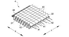
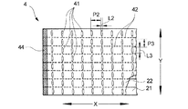
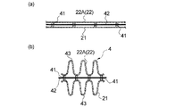
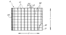
次に、本実施形態において胴回りギャザーG1及びウエストギャザーG2を形成する複合伸縮部4について詳述する。複合伸縮部4は、図10及び図11に示すように、下記(1)〜(3)の構成を具備している。
(1)外層シート21及び内層シート22は、複合伸縮部4の伸縮方向(X方向)及びそれに直交する方向(Y方向)において間欠的な接合部41により互いに接合されている。
(2)弾性部材42は、接合部41を通らないように配されると共に、弾性部材42の両端部において外層シート21及び内層シート22に固定されている。
(3)外層シート21及び内層シート22それぞれは、各々複数本の弾性部材42に亘って連続して延びる複数本の襞43を形成している。
Next, the composite elastic part 4 which forms the waistline gather G1 and the waist gather G2 in this embodiment is explained in full detail. As shown in FIGS. 10 and 11, the composite stretchable part 4 has the following configurations (1) to (3).
(1) The outer layer sheet 21 and the inner layer sheet 22 are joined to each other by an intermittent joining portion 41 in the stretching direction (X direction) of the composite stretchable portion 4 and the direction (Y direction) perpendicular thereto.
(2) The elastic member 42 is disposed so as not to pass through the joint portion 41, and is fixed to the outer layer sheet 21 and the inner layer sheet 22 at both ends of the elastic member 42.
(3) Each of the outer layer sheet 21 and the inner layer sheet 22 forms a plurality of ridges 43 extending continuously over a plurality of elastic members 42.

複合伸縮部4から形成された胴回りギャザーG1は、外層シート21、内層シート22及び胴回り弾性部材23を主体として構成されており、複合伸縮部4から形成されたウエストギャザーG2は、外層シート21、内層シート22及びウエスト弾性部材24を主体として構成されている。このように、ギャザーによってそれを構成する弾性部材が異なるが、以下の複合伸縮部4の説明においては、複合伸縮部4を構成する弾性部材を「弾性部材42」として説明する。
尚、図1、図2、図13等においては、接合部41の図示を省略している。
The waistline gather G1 formed from the composite stretchable part 4 is mainly composed of the outer layer sheet 21, the inner layer sheet 22, and the waistline elastic member 23. The waist gather G2 formed from the composite stretchable part 4 is composed of the outer layer sheet 21, The inner layer sheet 22 and the waist elastic member 24 are mainly configured. Thus, although the elastic member which comprises it changes with gathers, in the following description of the composite expansion-contraction part 4, the elastic member which comprises the composite expansion-contraction part 4 is demonstrated as the "elastic member 42".
In addition, in FIG.1, FIG.2, FIG.13 etc., illustration of the junction part 41 is abbreviate | omitted.

本実施形態の複合伸縮部4においては、弾性部材42の伸縮力を充分に生かすため、全ての弾性部材42が全ての接合部41を通らないように構成されていることが好ましいが、例えば、製造誤差上、若干の弾性部材42が一部の接合部41を通ってしまうことがある。弾性部材42の伸縮力を阻害しない範囲で、若干の弾性部材42が一部〔例えば30%以下(個/個)〕の接合部41を通ってもよい。
接合部41には、外層シート21と内層シート22との接合を達成するために、接合方法によって大きな加圧力が加わることがある。このような接合方法においては、弾性部材42が接合部41を通る場合には、弾性部材42を切断する可能性が大きいため、弾性部材42が接合部41を通らないように構成することが好ましい。
In the composite elastic part 4 of this embodiment, in order to make full use of the elastic force of the elastic member 42, it is preferable that all the elastic members 42 do not pass through all the joint parts 41. Some elastic members 42 may pass through some of the joints 41 due to manufacturing errors. Some elastic members 42 may pass through a part [for example, 30% or less (pieces / pieces)] of the joint portions 41 as long as the elastic force of the elastic members 42 is not hindered.
In order to achieve the joining of the outer layer sheet 21 and the inner layer sheet 22, a large pressing force may be applied to the joining portion 41 depending on the joining method. In such a joining method, when the elastic member 42 passes through the joint portion 41, it is highly possible that the elastic member 42 is cut. Therefore, the elastic member 42 is preferably configured not to pass through the joint portion 41. .

複合伸縮部4を構成する外層シート21及び内層シート22は、図10及び図11に示すように、複合伸縮部4の伸縮方向(X方向)及びそれに直交する方向(Y方向)のそれぞれにおいて、接合部41により間欠的に互いに接合されている。接合部41は、好ましくは外層シート21と内層シート22との熱融着により形成される。
複数本の弾性部材42は、互いに平行に配されており、それぞれ複合伸縮部4の長手方向に沿って延びるように配されている。本実施形態のように複数本の弾性部材42が互いに平行に配されている場合においては、複合伸縮部4の伸縮方向は、弾性部材42が延びる方向と同じ方向である。複数本の弾性部材42が互いに平行に配されていない場合においては、複合伸縮部4の伸縮方向は、複数本の弾性部材42に亘って延びる襞43(後述)における襞43が延びる方向に直交する方向とする。
As shown in FIGS. 10 and 11, the outer layer sheet 21 and the inner layer sheet 22 constituting the composite stretchable part 4 are respectively in the stretch direction (X direction) of the composite stretchable part 4 and the direction (Y direction) perpendicular thereto. The joints 41 are intermittently joined together. The joining portion 41 is preferably formed by thermal fusion between the outer layer sheet 21 and the inner layer sheet 22.
The plurality of elastic members 42 are arranged in parallel to each other, and are arranged so as to extend along the longitudinal direction of the composite stretchable part 4. When a plurality of elastic members 42 are arranged in parallel to each other as in the present embodiment, the expansion / contraction direction of the composite expansion / contraction part 4 is the same direction as the direction in which the elastic member 42 extends. In the case where the plurality of elastic members 42 are not arranged in parallel to each other, the expansion / contraction direction of the composite expansion / contraction part 4 is orthogonal to the direction in which the flanges 43 (described later) extending over the plurality of elastic members 42 extend. Direction.

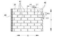
図11は、接合部41の配列パターンを示す図である。接合部41は、複合伸縮部4の伸縮方向(X方向)及びそれに直交する方向(Y方向)にそれぞれ列をなすように形成されており、該直交する方向の列を構成する接合部41が各弾性部材42同士の間毎に形成されている。そして、自然状態(外力を加えない状態)において、弾性部材42が収縮して、外層シート21及び内層シート22のそれぞれが、各々複数本の弾性部材42に亘って連続して延びる複数本の襞(ギャザー)43を形成している。本実施形態においては、複合伸縮部4の伸縮方向(X方向)において相隣接する接合部41,41間に、それぞれ一本の襞43が形成されている。   FIG. 11 is a diagram illustrating an arrangement pattern of the joint portions 41. The joint portions 41 are formed so as to form rows in the stretching direction (X direction) of the composite stretchable portion 4 and the direction (Y direction) perpendicular thereto, and the joint portions 41 constituting the row in the perpendicular direction are formed. It is formed between each elastic member 42. In a natural state (a state in which no external force is applied), the elastic member 42 contracts, and each of the outer layer sheet 21 and the inner layer sheet 22 continuously extends over the plurality of elastic members 42. (Gather) 43 is formed. In the present embodiment, a single collar 43 is formed between the joint portions 41, 41 adjacent to each other in the stretching direction (X direction) of the composite stretchable portion 4.

複数本の弾性部材42に亘って連続して延びる襞43を確実に形成させる観点から、複合伸縮部4の伸長時において、複合伸縮部4の伸縮方向(X方向)における接合部41のピッチP2(図11参照)は、1〜20mm、特に3〜12mmであることが好ましく、各接合部41の長さL2(図11参照)は、0.1〜5mm、特に0.2〜2.0mmであることが好ましい。前記ピッチP2と前記長さL2の比(P2/L2)は、1.1〜200、特に2〜50であることが好ましい。そうすることによって、ピッチP2だけ離間する隣り合う接合部41の間に、前記弾性部材42の収縮力が働き、襞43の成形性を高めることができる。   From the viewpoint of reliably forming the flanges 43 extending continuously over the plurality of elastic members 42, the pitch P <b> 2 of the joint portions 41 in the expansion / contraction direction (X direction) of the composite expansion / contraction portion 4 when the composite expansion / contraction portion 4 extends. (See FIG. 11) is preferably 1 to 20 mm, particularly 3 to 12 mm, and the length L2 (see FIG. 11) of each joint 41 is 0.1 to 5 mm, particularly 0.2 to 2.0 mm. It is preferable that The ratio (P2 / L2) between the pitch P2 and the length L2 is preferably 1.1 to 200, particularly 2 to 50. By doing so, the contraction force of the elastic member 42 works between the adjacent joint portions 41 separated by the pitch P2, and the formability of the flange 43 can be improved.

複合伸縮部4において、その伸縮方向に直交する方向(Y方向)における接合部41のピッチP3(図11参照)は、1〜40mm、特に2〜15mmであることが好ましく、各接合部41の長さL3(図11参照)は、0.5〜20mm、特に1〜10mmであることが好ましい。また、前記ピッチP3と前記長さL3の比(P3/L3)は、1.05〜80、特に1.05〜15であることが好ましい。   In the composite stretchable part 4, the pitch P3 (see FIG. 11) of the joints 41 in the direction (Y direction) orthogonal to the stretch direction is preferably 1 to 40 mm, particularly 2 to 15 mm. The length L3 (see FIG. 11) is preferably 0.5 to 20 mm, particularly 1 to 10 mm. Moreover, it is preferable that ratio (P3 / L3) of the said pitch P3 and the said length L3 is 1.05-80, especially 1.05-15.

前記ピッチと前記長さとの差(P2−L2)及び(P3−L3)は、どちらも襞43の均一な成形性を高める上で重要な数値である。前記差(P2−L2)が小さすぎず、大きすぎない数値を採ることで、外層シート21及び内層シート22が均一に座屈しやすくなる。また、前記差(P3−L3)が小さな値を採ることで、外層シート21及び内層シート22の座屈の起点を作ることとなり、成形性を高めることができる。
また、複数本の弾性部材42は、外層シート21及び内層シート22を配列方向に均一に収縮させ、成形性を確保する観点から、等間隔で配列されていることが好ましい。
The difference (P2-L2) and (P3-L3) between the pitch and the length are both important numerical values for improving the uniform formability of the flange 43. By taking a numerical value in which the difference (P2−L2) is not too small and not too large, the outer layer sheet 21 and the inner layer sheet 22 are likely to buckle uniformly. Moreover, since the difference (P3-L3) takes a small value, the starting point of buckling of the outer layer sheet 21 and the inner layer sheet 22 is made, and the moldability can be improved.
The plurality of elastic members 42 are preferably arranged at equal intervals from the viewpoint of uniformly shrinking the outer layer sheet 21 and the inner layer sheet 22 in the arrangement direction and ensuring formability.

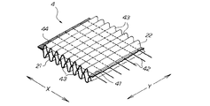
複合伸縮部4において、外層シート21及び内層シート22は、接合部41以外の部位においては互いに接合されていないことが好ましい。各弾性部材42は、外層シート21及び内層シート22同士の接合部41を通らないように複合伸縮部4に配されており、弾性部材42の両端部においてのみ、外層シート21及び内層シート22に固定されている。
弾性部材42の両端部は、複合伸縮部4の両端部44(一方のみ図示)において、外層シート21及び内層シート22に挟まれた状態で外層シート21と内層シート22との間に固定されている。複合伸縮部4の両端部44は、それによって形成されるギャザーによって異なる。第1実施形態においては、胴回りギャザーG1を形成する複合伸縮部4の両端部44は、吸収性本体3の側縁部近傍及びサイドシール部11であり、ウエストギャザーG2を形成する複合伸縮部4の両端部44は、両サイドシール部11,11である。
尚、複合伸縮部4の両端部44は伸縮可能に形成してもよい。
In the composite stretchable part 4, the outer layer sheet 21 and the inner layer sheet 22 are preferably not joined to each other at a part other than the joint part 41. Each elastic member 42 is arranged in the composite stretchable portion 4 so as not to pass through the joint portion 41 between the outer layer sheet 21 and the inner layer sheet 22, and only the both end portions of the elastic member 42 are connected to the outer layer sheet 21 and the inner layer sheet 22. It is fixed.
Both end portions of the elastic member 42 are fixed between the outer layer sheet 21 and the inner layer sheet 22 in a state sandwiched between the outer layer sheet 21 and the inner layer sheet 22 at both end portions 44 (only one is shown) of the composite stretchable portion 4. Yes. Both end portions 44 of the composite stretchable portion 4 differ depending on the gathers formed thereby. In 1st Embodiment, the both ends 44 of the composite expansion-contraction part 4 which forms the waistline gather G1 are the side edge part vicinity and the side seal part 11 of the absorptive main body 3, and the composite expansion-contraction part 4 which forms waist gathers G2 Both end portions 44 are both side seal portions 11, 11.
In addition, you may form the both ends 44 of the composite expansion-contraction part 4 so that expansion-contraction is possible.

外層シート21及び内層シート22における各襞43は、複合伸縮部4の両面それぞれに突出するように形成されており、各襞43の突出方向の先端部には、断面円弧状の凸曲面が形成されている。この凸曲面は、複合伸縮部4の伸縮方向に直交する方向(Y方向)に連続的に延びている。本実施形態においては、複合伸縮部4の伸縮方向(X方向)において相隣接する接合部41,41間に、それぞれ1本の襞43が形成されており、それらの襞43は、弾性部材42と重なる箇所において分断されることなく、複合伸縮部4の伸縮方向に直交する方向(Y方向)に連続的に延びている。   Each ridge 43 in the outer layer sheet 21 and the inner layer sheet 22 is formed so as to protrude from both surfaces of the composite stretchable portion 4, and a convex curved surface having an arcuate cross section is formed at the tip in the protruding direction of each ridge 43. Has been. The convex curved surface continuously extends in a direction (Y direction) orthogonal to the expansion / contraction direction of the composite expansion / contraction part 4. In the present embodiment, one ridge 43 is formed between the joint portions 41, 41 adjacent to each other in the expansion / contraction direction (X direction) of the composite expansion / contraction portion 4, and these ridges 43 are elastic members 42. Without being divided at the overlapping portion, and continuously extending in the direction (Y direction) orthogonal to the expansion / contraction direction of the composite expansion / contraction part 4.

本実施形態における複合伸縮部4は、弾性部材42の収縮により形成された多数の襞43,43のそれぞれが、複合伸縮部4の伸縮方向に直交する方向(Y方向)に連続的に延びているため、見た目に非常に美しい。   In the composite stretchable part 4 in this embodiment, each of a large number of ridges 43, 43 formed by contraction of the elastic member 42 extends continuously in a direction (Y direction) perpendicular to the stretchable direction of the composite stretchable part 4. So it looks very beautiful.

また、本実施形態における複合伸縮部4は、剛性の増加を防止できると共に、外力に対する襞43の変形自由度が向上している。この剛性の増加の防止及び襞43の変形自由度の向上は、弾性部材42が、外層シート21における襞43と襞43との間の谷部と、内層シート22における襞43と襞43との間の谷部との間に挟まれた状態で存在し、それらの谷部同士間に挟まれた部分を含めて、外層シート21及び内層シート22の何れにも接合されていない状態で存在すること、並びに複合伸縮部4における外層シート21及び内層シート22が複合伸縮部4の伸縮方向(X方向)及びそれに直交する方向(Y方向)の何れの方向においても連続的に接合されていないことに基づいている。
更に、襞43の先端が凸曲面を形成していることとの相乗効果により、外層シート21及び内層シート22の厚み方向にボリュームが出ると共に、複合伸縮部4の表面に触れたときの感触が極めて柔らかく、肌触りが極めて良好である。
Moreover, the composite elastic part 4 in this embodiment can prevent the increase in rigidity, and the degree of freedom of deformation of the flange 43 with respect to external force is improved. The prevention of the increase in rigidity and the improvement of the degree of freedom of deformation of the flange 43 are such that the elastic member 42 is formed between the valley between the flange 43 and the flange 43 in the outer layer sheet 21 and the flange 43 and the flange 43 in the inner layer sheet 22. It exists in a state of being sandwiched between the valleys between them, and is present in a state where it is not joined to any of the outer layer sheet 21 and the inner layer sheet 22 including the portion sandwiched between those valleys. In addition, the outer layer sheet 21 and the inner layer sheet 22 in the composite stretchable part 4 are not continuously joined in any of the stretchable direction (X direction) of the composite stretchable part 4 and the direction (Y direction) perpendicular thereto. Based on.
Furthermore, due to a synergistic effect with the tip of the collar 43 forming a convex curved surface, a volume appears in the thickness direction of the outer layer sheet 21 and the inner layer sheet 22 and the touch when touching the surface of the composite stretchable part 4 is felt. It is very soft and feels very good.

また、複合伸縮部4における弾性部材42が、外層シート21及び内層シート22に接合されていない状態で存在するため、ホットメルト型接着剤の使用量をゼロ又は少量に抑制することができる。特に本実施形態のように、外層シート21及び内層シート22同士の接合部41による接合を熱融着によって行なった場合には、接着剤の使用量の低減効果は一層顕著である。ホットメルト型接着剤の使用量が少ないので、通気性や透湿性を損なうこともない。   Moreover, since the elastic member 42 in the composite stretchable part 4 is present in a state where it is not joined to the outer layer sheet 21 and the inner layer sheet 22, the amount of hot melt adhesive used can be suppressed to zero or a small amount. In particular, as in the present embodiment, when the outer layer sheet 21 and the inner layer sheet 22 are joined to each other by the joining portion 41 by heat fusion, the effect of reducing the amount of adhesive used is more remarkable. Since the amount of hot-melt adhesive used is small, air permeability and moisture permeability are not impaired.

本実施形態における複合伸縮部4の形成材料について説明する。
外層シート21及び内層シート22としては、見た目に美しく、感触の良い柔軟な襞43を形成させる観点から、エアースルー不織布、ヒートロール不織布、スパンレース不織布、スパンボンド不織布、メルトブローン不織布、又はこれらの製法を組み合わせた多層からなる不織布等であることが好ましい。特に、感触及びコストの面からはエアスルー不織布が好ましく、その他の不織布を2次加工して柔らかくして使用することも可能である。
The material for forming the composite stretchable part 4 in this embodiment will be described.
As the outer layer sheet 21 and the inner layer sheet 22, from the viewpoint of forming a flexible ridge 43 that is beautiful to the eye and feels good, an air-through nonwoven fabric, a heat roll nonwoven fabric, a spunlace nonwoven fabric, a spunbond nonwoven fabric, a meltblown nonwoven fabric, or a production method thereof. It is preferable that it is the nonwoven fabric etc. which consist of a multilayer which combined these. In particular, an air-through nonwoven fabric is preferable from the viewpoint of feel and cost, and other nonwoven fabrics can be used after being secondarily processed.

複合伸縮部4においては、外層シート21及び内層シート22が弾性部材42の収縮に対して変形することにより襞43を形成する。つまり、外層シート21及び内層シート22の剛性が複合伸縮部4の襞43の成形性及びクッション性を決める要素の一つとなる。各シートの剛性はその座屈強度によって表すことができる。複合伸縮部4に用いられるシートの座屈強度は、100cN以下、特に70cN以下とすることが好ましい。ここで、座屈強度は、下記に示すように、テンシロン万能試験装置(株式会社オリエンテック製)の圧縮試験モードにより測定される。   In the composite stretchable part 4, the outer layer sheet 21 and the inner layer sheet 22 are deformed by the contraction of the elastic member 42 to form the flange 43. That is, the rigidity of the outer layer sheet 21 and the inner layer sheet 22 is one of the factors that determine the formability and cushioning properties of the collar 43 of the composite stretchable part 4. The rigidity of each sheet can be expressed by its buckling strength. The buckling strength of the sheet used for the composite stretchable part 4 is preferably 100 cN or less, particularly preferably 70 cN or less. Here, the buckling strength is measured by a compression test mode of a Tensilon universal testing device (manufactured by Orientec Co., Ltd.) as shown below.

座屈強度試験法(CD):
機械流れ方向(MD)の長さが150mm、機械流れ方向と直交する方向(CD)の長さ30mmの長方形状の試験片を丸めて、直径45mmの円筒を作成し、重なり合った部分の上端と下端とをホッチキス等で止め、測定サンプルとする。これを、テンシロン万能試験装置の圧縮試験モードにより、20℃、65%RHの測定環境において、圧縮速度10mm/min、測定距離20mmの測定条件で測定を行う。測定サンプルを20mm圧縮したときの最大強度を各測定サンプル毎に測定し、その平均値を求め、これを座屈強度とする。
Buckling strength test method (CD):
A rectangular test piece having a length of 150 mm in the machine flow direction (MD) and a length of 30 mm in the direction orthogonal to the machine flow direction (CD) is rounded to create a cylinder having a diameter of 45 mm. The lower end is stopped with a stapler or the like to obtain a measurement sample. This is measured by the compression test mode of the Tensilon universal testing apparatus in a measurement environment of 20 ° C. and 65% RH under measurement conditions of a compression speed of 10 mm / min and a measurement distance of 20 mm. The maximum strength when the measurement sample is compressed by 20 mm is measured for each measurement sample, the average value is obtained, and this is taken as the buckling strength.

前述したように、外層シート21及び内層シート22としては不繊布が好ましく用いられる。不織布の坪量は、好ましくは5〜50g/m2、特に好ましくは18〜30g/m2である。このような坪量を有する不織布の座屈強度は、CD方向において、好ましくは50cN以下、特に好ましくは30cN以下であり、また、MD方向において、好ましくは70cN以下、特に好ましくは50cN以下である。 As described above, non-woven cloth is preferably used as the outer layer sheet 21 and the inner layer sheet 22. The basis weight of the nonwoven fabric is preferably 5 to 50 g / m 2 , particularly preferably 18 to 30 g / m 2 . The buckling strength of the nonwoven fabric having such a basis weight is preferably 50 cN or less, particularly preferably 30 cN or less in the CD direction, and preferably 70 cN or less, particularly preferably 50 cN or less in the MD direction.

また、外層シート21及び内層シート22は、熱融着による接合(接合部41の形成)を容易にする観点から、その形成素材(不織布の場合は繊維)が熱融着性の樹脂からなることが好ましい。熱融着性の樹脂としては、ポリエチレン、ポリプロピレン等が挙げられる。繊維は、鞘が熱融着性の樹脂からなる芯鞘型の複合繊維等であってもよい。
外層シート21と内層シート22とは、形成材料が同一であってもよく、異なっていてもよい。
In addition, the outer layer sheet 21 and the inner layer sheet 22 are made of a heat-fusible resin from the viewpoint of facilitating joining by heat-sealing (formation of the joining portion 41). Is preferred. Examples of the heat-fusible resin include polyethylene and polypropylene. The fiber may be a core-sheath type composite fiber whose sheath is made of a heat-fusible resin.
The outer layer sheet 21 and the inner layer sheet 22 may be formed of the same material or different materials.

本発明における外層シート21及び内層シート22は、別体の2枚のシートに限られるものではなく、一枚のシートを折り曲げて相対向する2面を形成し、一方の面を構成する部分を外層シート21、他方の面を構成する部分を内層シート22とすることもできる。   The outer layer sheet 21 and the inner layer sheet 22 in the present invention are not limited to two separate sheets, but two sheets facing each other are formed by bending one sheet, and a portion constituting one surface is formed. The outer layer sheet 21 and the portion constituting the other surface can also be used as the inner layer sheet 22.

複合伸縮部4における弾性部材42の形成材料としては、使い捨ておむつや生理用ナプキン等の吸収性物品に用いられる各種公知の弾性材料を特に制限なく用いることができる。弾性材料としては、例えば、スチレン−ブタジエン、ブタジエン、イソプレン、ネオプレン等の合成ゴム、天然ゴム、EVA、伸縮性ポリオレフィン、ポリウレタン等を挙げることができる。弾性部材42の形態としては、断面が矩形、正方形、円形、多角形状等の糸状若しくは紐状(平ゴム等)のもの、又はマルチフィラメントタイプの糸状のもの等を用いることができる。   As a material for forming the elastic member 42 in the composite stretchable part 4, various known elastic materials used for absorbent articles such as disposable diapers and sanitary napkins can be used without particular limitation. Examples of the elastic material include synthetic rubber such as styrene-butadiene, butadiene, isoprene, and neoprene, natural rubber, EVA, stretchable polyolefin, and polyurethane. As the form of the elastic member 42, a cross-sectionally rectangular, square, circular, polygonal or other thread-like or string-like (flat rubber etc.) or multifilament-type thread-like one can be used.

複合伸縮部4の襞43の成形性を決めるもう一つの要素は、弾性部材42の伸長倍率及び伸縮応力である。襞43の断面形状を凸形状にするためには、所要の弾性部材42の伸長倍率及び伸縮応力が必要となる。弾性部材42は、好ましくは20〜1000%、特に好ましくは50〜400%の伸長状態にて外層シート21及び内層シート22に接合される。そして、弾性部材42が収縮し、収縮した部分の外層シート21及び内層シート22が余り、余った外層シート21及び内層シート22が、接合部41の貼り合わせ面とは反対側の方向に(外側に)断面凸形状に変形することによって襞43が形成される。   Another factor that determines the formability of the collar 43 of the composite stretchable part 4 is the stretch ratio and stretch stress of the elastic member 42. In order to make the cross-sectional shape of the flange 43 convex, the required expansion ratio and expansion / contraction stress of the elastic member 42 are required. The elastic member 42 is preferably bonded to the outer layer sheet 21 and the inner layer sheet 22 in a stretched state of 20 to 1000%, particularly preferably 50 to 400%. Then, the elastic member 42 contracts, the contracted portions of the outer layer sheet 21 and the inner layer sheet 22 remain, and the remaining outer layer sheet 21 and inner layer sheet 22 extend in the direction opposite to the bonding surface of the joint portion 41 (outside). (Ii) The ridge 43 is formed by deforming into a convex cross section.

以上のように、襞43の高さは、成形性及びクッション性に関連する重要な要素であり、接合部41の配列パターン及び間隔、外層シート21及び内層シート22の材料並びに弾性部材等の選択により、任意に設計することができる。この襞43の高さは,好ましくは片側1〜15mm程度である。襞43を高くするためには、相隣接する接合部41の間隔が詰まる程度に弾性部材42を収縮させて、凸形状の襞43を形成させることで、ボリューム感のある柔らかい複合伸縮部4を形成することができる。片側の高さがhの襞43を形成するときには、接合部41の間隔は最低でも2×hとすることが必要であり、接合部41の間隔が2×hの場合には、弾性部材42は、相隣接する接合部41が隣接する程度に収縮することが必要である。   As described above, the height of the flange 43 is an important element related to the moldability and cushioning properties, and the selection of the arrangement pattern and interval of the joint portions 41, the material of the outer layer sheet 21 and the inner layer sheet 22, the elastic member, and the like. Thus, it can be arbitrarily designed. The height of the flange 43 is preferably about 1 to 15 mm on one side. In order to increase the height of the flange 43, the elastic member 42 is contracted to the extent that the interval between the adjacent joint portions 41 is narrowed to form the convex flange 43, so that the soft composite stretchable portion 4 with a sense of volume is formed. Can be formed. When forming the flange 43 having a height on one side, the distance between the joint portions 41 needs to be at least 2 × h. When the distance between the joint portions 41 is 2 × h, the elastic member 42 is required. Needs to shrink to such an extent that adjacent joints 41 are adjacent.

好ましい弾性部材42の一つに、天然ゴム(又は合成ゴム)がある。天然ゴム(合成ゴム)としては、厚みが0.05〜1.5mm、幅が0.2〜5mmの低モジュラスの弾性部材が挙げられる。この弾性部材においては、単糸での100%伸長時の応力は、好ましくは1〜70gfであり、更に好ましくは1〜40gfであり、特に好ましくは1〜30gfである。上記低モジュラスの弾性部材の単糸を、好ましくは100%以上、特に好ましくは200%以上の高伸長倍率で複数本配することにより、柔らかく伸縮する美しい襞43を有する複合伸縮部4を得ることができる。   One of the preferable elastic members 42 is natural rubber (or synthetic rubber). Examples of natural rubber (synthetic rubber) include low modulus elastic members having a thickness of 0.05 to 1.5 mm and a width of 0.2 to 5 mm. In this elastic member, the stress at 100% elongation in a single yarn is preferably 1 to 70 gf, more preferably 1 to 40 gf, and particularly preferably 1 to 30 gf. By providing a plurality of single yarns of the elastic member having a low modulus at a high elongation ratio of preferably 100% or more, particularly preferably 200% or more, a composite stretchable part 4 having a beautiful heel 43 that stretches softly is obtained. Can do.

他の好ましい弾性部材としては、ポリウレタンのスパンデックス弾性繊維が挙げられる。この弾性繊維としては、単糸のサイズが10〜3360デニールのもの、特に好ましくは70〜1120デニールのものが用いられる。デニールは糸の太さを表す単位であり、9000mで1gある糸を1デニールと呼ぶ。このスパンデックス弾性繊維を30〜500%に伸長させて用いることが好ましい。   Other preferred elastic members include polyurethane spandex elastic fibers. As the elastic fiber, one having a single yarn size of 10 to 3360 denier, particularly preferably 70 to 1120 denier is used. Denier is a unit representing the thickness of a yarn, and a yarn of 1 g at 9000 m is called 1 denier. It is preferable to use the spandex elastic fiber by stretching it to 30 to 500%.

以上の構成を有する第1実施形態のパンツ型使い捨ておむつによれば、内層シート22は、外層シート21の長手方向端部よりも更に延出する長さを有し、外層シート21よりも延出した延出領域22Bが吸収性本体3側に折り返されており、折り返された内層シート22の延出領域22Bによって、吸収性本体3の長手方向端部における肌当接面側が覆われている。そのため、内層シート22の延出領域22Bを折り返すだけで、格別な位置合わせをしなくても、吸収性本体3の長手方向端部における肌当接面側を覆うことができ、おむつの長手方向端部近傍の形成が容易である。
また、端部近傍ギャザーであるウエストギャザーG2を形成する複合伸縮部4は、複合伸縮部4の収縮時に、外層シート21(外包材2)の長手方向端部において襞43の断面に開口部が形成されるため、排尿後、吸収体本体から非肌当接面側へ抜ける湿気が複合伸縮部内部の空洞を通り抜け、外層シート21(外包材2)の長手方向端部から湿気が放出される事で通気性に優れていると共に、優れた通気性を想起させる外観を呈することになる。外層シート21の長手方向端部からの通気性を向上させるため、吸収性本体の裏面シート33は透湿性があることが好ましい。
According to the pants-type disposable diaper of the first embodiment having the above-described configuration, the inner layer sheet 22 has a length that extends further than the longitudinal end portion of the outer layer sheet 21 and extends more than the outer layer sheet 21. The extended region 22 </ b> B is folded back toward the absorbent main body 3, and the skin contact surface side at the end in the longitudinal direction of the absorbent main body 3 is covered with the extended region 22 </ b> B of the folded inner layer sheet 22. Therefore, it is possible to cover the skin contact surface side at the end in the longitudinal direction of the absorbent main body 3 without remarkably aligning only by folding the extension region 22B of the inner layer sheet 22, and the longitudinal direction of the diaper. Formation near the end is easy.
Further, the composite stretchable part 4 forming the waist gather G2, which is a gather near the end, has an opening in the cross section of the flange 43 at the longitudinal end of the outer layer sheet 21 (outer packaging material 2) when the composite stretchable part 4 contracts. Therefore, after urination, moisture that passes from the absorbent body to the non-skin contact surface side passes through the cavity inside the composite stretchable part, and moisture is released from the longitudinal end of the outer layer sheet 21 (outer packaging material 2). In addition to being excellent in breathability, it has an appearance reminiscent of excellent breathability. In order to improve the air permeability from the end in the longitudinal direction of the outer layer sheet 21, the back sheet 33 of the absorbent main body is preferably moisture permeable.

また、胴回りギャザーG1及びウエストギャザーG2が、複合伸縮部4から形成されていることによって伸縮性が発現されるため、腹側部A及び背側部Bにおける通気性に優れている。また、外包材2の外層シート21及び内層シート22の素材本来の質感を活かすことができ、柔らかでゴワゴワしない。   In addition, since the waistline gather G1 and the waist gather G2 are formed from the composite stretchable part 4, stretchability is exhibited, and therefore, the ventilating part A and the backside part B have excellent air permeability. Moreover, the raw material original texture of the outer-layer sheet 21 and the inner-layer sheet 22 of the outer packaging material 2 can be utilized, and it is soft and not stiff.

複合伸縮部4においては、弾性部材42の収縮力が全く(又はほとんど)阻害されないため、収縮力が最大限活用される。従って、収縮力が高いため、着用者に優しくフィットし、ずれ落ちにくい。また、おむつ全体として最大限収縮するため、コンパクトに見えるという利点がある。同様の理由により、着用者のサイズ適用範囲が大きくなる。また、弾性部材42の収縮力が阻害されないということは、同じ伸長倍率としたときに弾性部材のサイズを小さくすることができるということであり、弾性部材42の使用量を削減できるので、コスト面でも有利である。   In the composite stretchable portion 4, the contraction force of the elastic member 42 is not (or hardly) inhibited, so that the contraction force is utilized to the maximum extent. Therefore, since the shrinkage force is high, it fits gently to the wearer and is difficult to slip off. Moreover, since the whole diaper shrinks to the maximum extent, there is an advantage that it looks compact. For the same reason, the size application range of the wearer is increased. Further, the fact that the contraction force of the elastic member 42 is not hindered means that the size of the elastic member can be reduced when the expansion ratio is the same, and the amount of use of the elastic member 42 can be reduced. But it is advantageous.

複合伸縮部4の外面に襞43が形成されており、襞43が着用者との接触面となるため、着用時に複合伸縮部4のクッション性が高く、優しくフィットし、着用者の肌へのダメージが少ない。また、襞43は外包材2の外面(着用時の外面)にも配されるため、外面の触感にも優れる。   Since the heel 43 is formed on the outer surface of the composite stretchable portion 4 and the heel 43 is a contact surface with the wearer, the composite stretchable portion 4 has a high cushioning property when worn and fits gently to the wearer's skin. Less damage. Moreover, since the collar 43 is also arranged on the outer surface of the outer packaging material 2 (the outer surface when worn), the outer surface feels excellent.

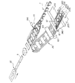
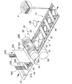
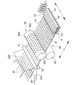
次に、第1実施形態のパンツ型使い捨ておむつの一製造方法について説明する。本製造方法は、第1実施形態のパンツ型使い捨ておむつ1を連続的に生産する方法である。図12は、本製造方法の全容を示す斜視図である。図13は、本製造方法のうち、複合伸縮部、非機能化領域及びレッグ弾性部材切断領域を形成する工程を中心として示す概念図である。図14は、本製造方法のうち、複合伸縮部を形成する工程を中心として示す概念図である。   Next, one manufacturing method of the underpants type disposable diaper of 1st Embodiment is demonstrated. This manufacturing method is a method for continuously producing the pants-type disposable diaper 1 of the first embodiment. FIG. 12 is a perspective view showing the entire manufacturing method. FIG. 13: is a conceptual diagram which mainly shows the process of forming a composite expansion-contraction part, a non-functionalization area | region, and a leg elastic member cutting area | region among this manufacturing methods. FIG. 14 is a conceptual diagram showing mainly the process of forming the composite stretchable part in the present manufacturing method.

本製造方法は、図12〜図14に示すように、外層シート21と内層シート22とを接合部41により接合して複合伸縮部4を形成する工程と、弾性部材23,26の収縮力を発現させなくして非機能化領域51を形成する工程とを、同一のロール62を用いて行っている。
本製造方法は、図12に示すように、外層シート21の連続体21Sと内層シート22の連続体22Sとをその間に各弾性部材23,24,25,26の各連続体23S,24S,25S,26Sを挟持接合して、外包材2の連続体2Sを形成し、次に、外包材連続体2Sにおける内層シート連続体22S側に吸収性本体3を本体接合部15(図4参照)によって接合して、おむつ連続体1Sを形成し、次いで、おむつ連続体1Sを分断して個々のおむつ1を形成するパンツ型使い捨ておむつの製造方法である。
In this manufacturing method, as shown in FIGS. 12 to 14, the outer layer sheet 21 and the inner layer sheet 22 are joined by the joining part 41 to form the composite stretchable part 4, and the contraction force of the elastic members 23 and 26 is applied. The same roll 62 is used for the step of forming the non-functionalized region 51 without making it appear.
In this manufacturing method, as shown in FIG. 12, the continuous body 21S of the outer layer sheet 21 and the continuous body 22S of the inner layer sheet 22 are interposed between the continuous bodies 23S, 24S, 25S of the elastic members 23, 24, 25, 26. , 26S are sandwiched and joined to form a continuous body 2S of the outer packaging material 2, and the absorbent main body 3 is then attached to the inner layer sheet continuous body 22S side of the outer packaging material continuous body 2S by the main body joining portion 15 (see FIG. 4). It is the manufacturing method of the underpants type disposable diaper which joins and forms the diaper continuous body 1S, and then divides the diaper continuous body 1S and forms each diaper 1.

本製造方法について詳述する。外層シート21の原反として外層シート連続体21Sを使用し、内層シート22の原反として内層シート連続体22Sを使用する。
各弾性部材23,24,25,26の各連続体23S,24S,25S,26Sは、伸長された状態で、外層シート連続体21Sと内層シート連続体22Sとの間に導入される。尚、図13においては、前股間弾性部材26の連続体26Sの図示を省略している。外層シート連続体21Sと内層シート連続体22Sとが合流する前には、それぞれの対向面側に、接着剤塗工装置64(図13参照)等によって、図8及び図9に示す塗工位置にホットメルト型接着剤Qが塗工される。また、レッグ弾性部材25の連続体25Sは、揺動ガイド65(図13参照)によりレッグ開口部13の形状に沿うように揺動されながら、外層シート連続体21Sと内層シート連続体22Sとの間に導入される。
This manufacturing method will be described in detail. The outer layer sheet continuous body 21 </ b> S is used as the original sheet of the outer layer sheet 21, and the inner layer sheet continuous body 22 </ b> S is used as the original sheet of the inner layer sheet 22.
Each continuous body 23S, 24S, 25S, 26S of each elastic member 23, 24, 25, 26 is introduced between the outer layer sheet continuous body 21S and the inner layer sheet continuous body 22S in an expanded state. In addition, in FIG. 13, illustration of the continuous body 26S of the front crotch elastic member 26 is abbreviate | omitted. Before the outer layer sheet continuous body 21S and the inner layer sheet continuous body 22S merge, the coating positions shown in FIGS. 8 and 9 are formed on the respective facing surfaces by the adhesive coating device 64 (see FIG. 13) or the like. The hot melt adhesive Q is applied to the surface. Further, the continuum 25S of the leg elastic member 25 is swung along the shape of the leg opening 13 by the swing guide 65 (see FIG. 13), while the outer layer sheet continuum 21S and the inner layer sheet continuum 22S. Introduced between.

両シート連続体21S,22Sは、各弾性部材連続体23S,24S,25S,26Sを挟んだ状態で、一対のニップロール61,61間で狭圧される。その結果、両シート連続体21S,22S間に各弾性部材連続体23S,24S,25S,26Sが挟持接合されてなる外包材連続体2Sが得られる。ここで、胴回り弾性部材23は、吸収性本体3の側縁部近傍とサイドシール部11との間となる領域においては、ホットメルト型接着剤Qによって接合されていない。同様に、ウエスト弾性部材24は、一対のサイドシール部11の間となる領域においては、ホットメルト型接着剤Qによって接合されていない。
この時点では、外包材連続体2Sには、複合伸縮部4、非機能化領域51及びレッグ弾性部材切断領域52は形成されていない。
Both sheet continuums 21S and 22S are compressed between the pair of nip rolls 61 and 61 with the elastic member continuums 23S, 24S, 25S, and 26S sandwiched therebetween. As a result, an outer packaging material continuum 2S is obtained in which the elastic member continuums 23S, 24S, 25S, and 26S are sandwiched and joined between the sheet continuums 21S and 22S. Here, the waistline elastic member 23 is not joined by the hot-melt adhesive Q in a region between the side edge portion of the absorbent main body 3 and the side seal portion 11. Similarly, the waist elastic member 24 is not joined by the hot melt adhesive Q in a region between the pair of side seal portions 11.
At this time, the composite stretchable part 4, the non-functionalized region 51, and the leg elastic member cutting region 52 are not formed in the outer packaging material continuous body 2S.

次に、複合伸縮部4等が形成されていない外包材連続体2Sは、複合伸縮部形成ロール62とアンビルロール63との間に導入される。複合伸縮部形成ロール62は、その周面に、複合伸縮部4を形成する複合伸縮部形成部62Aを備えると共に、非機能化領域51を形成する非機能化領域形成部62B及びレッグ弾性部材切断領域52を形成するレッグ弾性部材切断領域形成部62Cを備えている。尚、図13においては、胴回りギャザーG1の複合伸縮部4を形成する複合伸縮部形成部62Aを図示してあるが、ウエストギャザーG2の複合伸縮部4を形成する複合伸縮部形成部の図示を省略している。
アンビルロール63は複合伸縮部形成ロール62の受けロールであり、その周面は平滑面となっている。
Next, the outer wrapping material continuous body 2 </ b> S in which the composite stretchable part 4 or the like is not formed is introduced between the composite stretchable part forming roll 62 and the anvil roll 63. The composite stretchable part forming roll 62 includes a composite stretchable part forming part 62A that forms the composite stretchable part 4 on its peripheral surface, and a non-functionalized region forming part 62B that forms the nonfunctionalized region 51 and leg elastic member cutting. A leg elastic member cutting region forming part 62 </ b> C that forms the region 52 is provided. In FIG. 13, the composite stretchable part forming part 62A that forms the composite stretchable part 4 of the waistline gather G1 is illustrated, but the composite stretchable part forming part that forms the composite stretchable part 4 of the waist gather G2 is illustrated. Omitted.
The anvil roll 63 is a receiving roll for the composite stretchable part forming roll 62, and its peripheral surface is a smooth surface.

複合伸縮部形成ロール62の複合伸縮部形成部62Aには、複合伸縮部4の接合部41に対応して多数のエンボスピン62D(図14参照。図13では図示省略)が設けられており、複合伸縮部形成部62Aによれば、複合伸縮部4が形成されていない外包材連続体2Sにおける複合伸縮部4に対応する領域に、接合部41を形成することができる。エンボスピン62Dは、ヒートエンボスピンでもよく、超音波エンボスピンでもよい。尚、図14は、複合伸縮部4を形成する工程に密接した要素のみを抜き出して示す概念図である。従って、例えば、複合伸縮部形成ロール62の周面には複合伸縮部形成部62Aのみを図示してあり、外包材連続体2Sについては複合伸縮部4のみを図示してある。   A plurality of embossed pins 62D (see FIG. 14; not shown in FIG. 13) are provided in the composite stretchable part forming part 62A of the composite stretchable part forming roll 62 corresponding to the joint part 41 of the composite stretchable part 4. According to the composite stretchable part forming part 62A, the joint part 41 can be formed in a region corresponding to the composite stretchable part 4 in the outer packaging material continuous body 2S in which the composite stretchable part 4 is not formed. The emboss spin 62D may be a heat emboss spin or an ultrasonic emboss spin. FIG. 14 is a conceptual diagram showing only elements closely related to the process of forming the composite stretchable part 4. Therefore, for example, only the composite stretchable part forming part 62A is illustrated on the peripheral surface of the composite stretchable part forming roll 62, and only the composite stretchable part 4 is illustrated for the outer packaging material continuous body 2S.

本製造方法においては、外層シート21及び内層シート22に接合部41を弾性部材23,24に干渉させずに形成して、複合伸縮部4を形成することが好ましい。つまり、複合伸縮部4の形成の際には、接合部41と弾性部材連続体23S,24Sとが干渉しないようにすることが好ましい。接合部41を熱融着により形成する場合には、接合させる部分に大きな加圧力が加わるため、弾性部材連続体23S,24Sに接合部41が干渉すると、弾性部材連続体23S,24Sが切断される可能性が高い。そのために、両シート連続体21S,22Sの間に導入される弾性部材連続体23S、24Sを、その導入位置を正確にコントロールしながら、複合伸縮部形成ロール62とアンビルロール63との間に導入する。これらの搬送系においては、各連続材料21S,22S,23S,24Sのテンションなどが安定した状態にあることが必須である。   In the present manufacturing method, it is preferable to form the composite stretchable part 4 by forming the joining part 41 in the outer layer sheet 21 and the inner layer sheet 22 without interfering with the elastic members 23 and 24. In other words, it is preferable that the joint 41 and the elastic member continuous bodies 23S and 24S do not interfere with each other when the composite stretchable part 4 is formed. When the joining portion 41 is formed by thermal fusion, a large pressing force is applied to the joined portions. Therefore, if the joining portion 41 interferes with the elastic member continuous bodies 23S and 24S, the elastic member continuous bodies 23S and 24S are cut. There is a high possibility. Therefore, the elastic member continuous bodies 23S and 24S introduced between the two sheet continuous bodies 21S and 22S are introduced between the composite stretchable part forming roll 62 and the anvil roll 63 while accurately controlling the introduction position. To do. In these transport systems, it is essential that the tension of each continuous material 21S, 22S, 23S, 24S is in a stable state.

そして、接合部41と弾性部材連続体23S,24Sとを干渉させない方法としては、各工程間の距離をできるだけ短く配置することが好ましい。特に重要なのは、弾性部材連続体23S,24Sの(弾性部材)導入ロール66と、一対のニップロール61、61と、一対の複合伸縮部形成ロール62及びアンビルロール63との3者間の距離である。各工程間の距離は、物理的に可能な範囲で最短距離とすることが好ましい。   And as a method which does not make the junction part 41 and elastic member continuous body 23S, 24S interfere, it is preferable to arrange | position the distance between each process as short as possible. Of particular importance is the distance between the three members of the elastic member continuum 23S, 24S (elastic member) introduction roll 66, the pair of nip rolls 61, 61, the pair of composite stretchable part forming rolls 62 and the anvil roll 63. . The distance between the steps is preferably the shortest distance within a physically possible range.

弾性部材連続体23S,24Sの導入ロール66から一対のニップロール61、61の挟圧点までの距離は、好ましくは10〜1,000mm、特に好ましくは、10〜300mmである。同様に、一対のニップロール61、61の挟圧点から一対の複合伸縮部形成ロール62とアンビルロール63との接点までの距離は、好ましくは10mm〜1,000mm、特に好ましくは10〜500mmである。
また、弾性部材導入ロール66においては、ロール自体のスラスト方向のガタがないこと、及び蛇行の要因となるロール溝の幅が狭く設計されていることが必要である。例えば、ロール溝の形状は、U字状断面ではなく、遊びの少ないV字状断面であることが好ましい。
The distance from the introduction roll 66 of the elastic member continuous body 23S, 24S to the pinching point of the pair of nip rolls 61, 61 is preferably 10 to 1,000 mm, and particularly preferably 10 to 300 mm. Similarly, the distance from the pinching point of the pair of nip rolls 61, 61 to the contact point between the pair of composite stretchable part forming rolls 62 and the anvil roll 63 is preferably 10 mm to 1,000 mm, particularly preferably 10 to 500 mm. .
Further, the elastic member introduction roll 66 needs to be designed so that there is no backlash in the thrust direction of the roll itself and that the width of the roll groove that causes meandering is narrow. For example, the shape of the roll groove is preferably not a U-shaped cross section but a V-shaped cross section with little play.

そして、図15及び図16に示すように、弾性部材42(本実施態様では胴回り弾性部材23、ウエスト弾性部材24が該当する)を収縮させて両シート連続体21S,22Sのそれぞれに複数本の襞43を形成させることにより、外包材連続体2Sの所定領域には、胴回りギャザーG1及びウエストギャザーG2を形成する複合伸縮部4が得られる。内層シート22の延出領域22Bが存在する領域においては、図16に示すように、延出領域22Bも襞形状となる。
尚、図15は、内層シート22の延出領域22Bが存在しない領域における複合伸縮部4を示す断面図であり、図16は、延出領域22Bが存在する領域における複合伸縮部4を示す断面図である。
As shown in FIGS. 15 and 16, the elastic member 42 (corresponding to the waistline elastic member 23 and the waist elastic member 24 in this embodiment) is contracted, and a plurality of sheets are provided on each of the two sheet continuous bodies 21S and 22S. By forming the collar 43, the composite stretchable part 4 that forms the waistline gather G1 and the waist gather G2 is obtained in a predetermined region of the outer packaging material continuous body 2S. In the region where the extension region 22B of the inner layer sheet 22 exists, the extension region 22B also has a hook shape as shown in FIG.
15 is a cross-sectional view showing the composite stretchable part 4 in the area where the extension region 22B of the inner layer sheet 22 does not exist, and FIG. 16 is a cross-section showing the composite stretchable part 4 in the area where the extension region 22B exists. FIG.

複合伸縮部形成ロール62の非機能化領域形成部62Bは、弾性部材の収縮力を発現させなくする部位であり、外包材連続体2Sに非機能化領域51を形成することができる。非機能化領域形成部62Bは、弾性部材を2つに又は多数に分断する凸部やカッター刃、弾性部材を熱シールによって硬化させる多数のエンボスピン等から構成されている。   The non-functionalized region forming part 62B of the composite stretchable part forming roll 62 is a part that prevents the contractive force of the elastic member from being expressed, and can form the non-functionalized region 51 in the outer packaging material continuous body 2S. The non-functionalized region forming portion 62B is configured by a convex portion or a cutter blade that divides the elastic member into two or a large number, a large number of emboss pins that harden the elastic member by heat sealing, and the like.

複合伸縮部形成ロール62のレッグ弾性部材切断領域形成部62Cは、股下部Cの幅方向中央部となる位置に存するレッグ弾性部材連続体25Sを切断する部位であり、レッグ弾性部材切断領域52を形成することができる。レッグ弾性部材切断領域形成部62Cは、例えば凸部やカッター刃から構成されている。レッグ弾性部材切断領域形成部62Cによれば、レッグ弾性部材連続体25Sを切断することにより、股下部Cの幅方向中央において幅方向に分離したレッグ弾性部材25,25を得ることができる。   The leg elastic member cutting region forming part 62C of the composite stretchable part forming roll 62 is a part for cutting the leg elastic member continuous body 25S existing at the position of the crotch part C in the center in the width direction. Can be formed. The leg elastic member cutting region forming part 62C is composed of, for example, a convex part or a cutter blade. According to the leg elastic member cutting region forming portion 62C, the leg elastic members 25, 25 separated in the width direction at the center in the width direction of the crotch C can be obtained by cutting the leg elastic member continuous body 25S.

以上の構成を有する複合伸縮部形成ロール62と、アンビルロール63との間に、複合伸縮部4、非機能化領域51及びレッグ弾性部材切断領域52が形成されていない外包材連続体2Sを挿通させることにより、所定領域に複合伸縮部4、非機能化領域51及びレッグ弾性部材切断領域52が形成された外包材連続体2Sが得られる。   Between the composite stretchable part forming roll 62 having the above configuration and the anvil roll 63, the outer envelope material continuous body 2S in which the composite stretchable part 4, the non-functionalized area 51, and the leg elastic member cutting area 52 are not formed is inserted. By doing so, the outer packaging material continuous body 2S in which the composite stretchable part 4, the non-functionalized region 51, and the leg elastic member cutting region 52 are formed in a predetermined region is obtained.

前記実施形態のパンツ型使い捨ておむつ1は、複合伸縮部4、非機能化領域51及びレッグ弾性部材切断領域52が形成された外包材連続体2Sを用いて、それ以降の各工程を、従来のいわゆる横流れ方式のパンツ型使い捨ておむつの製造方法における各工程と同様に行うことにより、製造することができる。
例えば、図12に示すように、外包材連続体2S上に、吸収性本体連続体3Sを切断して得た吸収性本体3を、それぞれ流れ方向に対して90度回転させた後、本体接合部15(図4参照)により間欠的に接合固定する。吸収性本体3の外包材連続体2Sへの固定は、外包材連続体2Sの伸長状態を維持したままで行う。換言すれば、外包材連続体2Sが複合伸縮部4等の収縮力により縮まないように維持しながら、吸収性本体3を固定する。吸収性本体3にもその長手方向に収縮する弾性部材(前記実施形態においては、側方カフス弾性部材36)が配設されていることが一般的であるが、そのような場合にも、吸収性本体3を、収縮しないように維持しながら外包材連続体2Sに対して固定する。
The pants-type disposable diaper 1 of the above embodiment uses the outer packaging material continuum 2S in which the composite stretchable part 4, the non-functionalized region 51, and the leg elastic member cutting region 52 are formed. It can manufacture by performing similarly to each process in the manufacturing method of what is called a cross-flow type underpants type disposable diaper.
For example, as shown in FIG. 12, after the absorbent main body 3 obtained by cutting the absorbent main body continuous body 3S on the outer packaging material continuous body 2S is rotated by 90 degrees with respect to the flow direction, the main body bonding is performed. The parts 15 (see FIG. 4) are joined and fixed intermittently. The absorbent main body 3 is fixed to the outer packaging material continuum 2S while maintaining the extended state of the outer packaging material continuum 2S. In other words, the absorbent main body 3 is fixed while maintaining the outer wrapping material continuous body 2 </ b> S so as not to shrink due to the shrinkage force of the composite stretchable part 4 or the like. The absorbent main body 3 is also generally provided with an elastic member that contracts in the longitudinal direction (in the embodiment, the side cuff elastic member 36). The sex main body 3 is fixed to the outer packaging material continuum 2S while keeping it from shrinking.

次に、図12に示すように、内層シート連続体22Sの両側部(延出領域22Bに対応する領域)を、吸収性本体3の両端部を覆うように折り返して、吸収性本体3の両端部に固定した後、外包材連続体2Sを吸収性本体3と共に2つ折りする。内層シート連続体22Sにおける延出領域22Bの内面側、それに対向する非延出領域22A、吸収性本体3等の所定位置には、予め接着剤Qを塗工しておく。
また、図12及び図13に示すように、ロータリーカッター、レーザーカッター等により、外包材連続体2Sからレッグ開口部形成用のトリム13Sを除去して、おむつ連続体1Sを得る。
Next, as shown in FIG. 12, both side portions (regions corresponding to the extension region 22 </ b> B) of the inner layer continuous sheet 22 </ b> S are folded back so as to cover both end portions of the absorbent main body 3. After fixing to the part, the outer packaging material continuous body 2 </ b> S is folded in two together with the absorbent main body 3. The adhesive Q is applied in advance to predetermined positions of the inner surface side of the extension region 22B in the inner layer continuous sheet 22S, the non-extension region 22A facing the extension region 22A, the absorbent main body 3, and the like.
Moreover, as shown in FIG.12 and FIG.13, the trim 13S for leg opening part formation is removed from the outer packaging material continuous body 2S with a rotary cutter, a laser cutter, etc., and the diaper continuous body 1S is obtained.

その後、おむつ連続体1Sをその幅方向(使い捨ておむつ1の長手方向)に折り返して2つ折りする。次いで、サイドシール部11,11を、ヒートシール、超音波シール、高周波シール等により形成した後、又はサイドシール部11,11を形成すると同時に、個々のおむつに分断することにより、前記実施形態のパンツ型使い捨ておむつ1を得ることができる。   Then, the diaper continuous body 1S is folded back in the width direction (longitudinal direction of the disposable diaper 1) and folded in two. Next, after forming the side seal portions 11 and 11 by heat sealing, ultrasonic sealing, high frequency sealing or the like, or simultaneously with the formation of the side seal portions 11 and 11, the side seal portions 11 and 11 are divided into individual diapers. A pants-type disposable diaper 1 can be obtained.

吸収性本体3を90度回転して外包材連続体2S上に間欠固定する方法としては、例えば、特開平4−166150号公報に記載の方法を用いることができる。また、吸収性本体3を外包材連続体2Sに固定する本体接合部15(図4参照)は、吸収性本体3及び外包材連続体2Sの何れか一方又は両方に塗工しておくことができる。また、レッグ開口部形成用のトリム13Sの除去は、外包材連続体2Sに吸収性本体3を固定する前に行うこともできる。   As a method of intermittently fixing the absorbent main body 3 by 90 degrees and intermittently fixing it on the outer packaging material continuum 2S, for example, a method described in JP-A-4-166150 can be used. Further, the main body joint 15 (see FIG. 4) for fixing the absorbent main body 3 to the outer packaging material continuum 2S may be applied to one or both of the absorbent main body 3 and the outer packaging material continuum 2S. it can. The trim 13S for forming the leg opening can be removed before the absorbent main body 3 is fixed to the outer packaging material continuous body 2S.

本製造方法によれば、外層シート21と内層シート22とを接合部41により接合して複合伸縮部4を形成する工程と、弾性部材23,26の収縮力を発現させなくして非機能化領域51を形成する工程とを、同一のロール62を用いて行っているため、複合伸縮部4及び非機能化領域51を備えたパンツ型使い捨ておむつを効率的に生産することができる。   According to this manufacturing method, the outer layer sheet 21 and the inner layer sheet 22 are joined by the joining part 41 to form the composite stretchable part 4, and the contraction force of the elastic members 23 and 26 is not expressed and the non-functionalized region Since the process of forming 51 is performed using the same roll 62, the underpants type disposable diaper provided with the composite expansion-contraction part 4 and the non-functionalization area | region 51 can be produced efficiently.

次に、本発明のパンツ型吸収性物品の他の実施形態について説明する。他の実施形態については、上述した第1実施形態と異なる点を主として説明し、同様の点は同一の符号を付して説明を省略する。特に説明しない点は、第1実施形態についての説明が適宜適用される。他の実施形態においても、第1実施形態と同様の効果が奏される。   Next, other embodiments of the pant-type absorbent article of the present invention will be described. In the other embodiments, differences from the first embodiment described above will be mainly described, and the same points are denoted by the same reference numerals and description thereof will be omitted. For the points that are not particularly described, the description of the first embodiment is applied as appropriate. In other embodiments, the same effects as those of the first embodiment can be obtained.

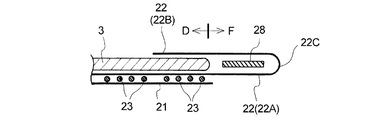
第2実施形態のパンツ型使い捨ておむつは、図17に示すように、第1実施形態に比して、複合伸縮部4から形成された端部近傍ギャザーの構成等が異なる。
具体的には、第2実施形態においては、図17に示すように、第1実施形態に比して、外層シート21は、その長手方向端部が、内層シート22における折り返し部22Cよりも長手方向内方に後退しており、外包材2のウエスト開口部12近傍(ウエスト部F)には実質的に存在していない。また、外包材2のウエスト開口部12近傍には、複合伸縮部4から形成されたウエストギャザーG2は設けられておらず、前記端部近傍ギャザーは、外包材2の腹側部A及び背側部Bにおける胴回り部Dに設けられた胴回りギャザーG1である。
ウエスト開口部12近傍(ウエスト部F)においては、内層シート22における非延出領域22Aと延出領域22Bとの間に、帯状又は糸状の弾性部材28が、実質的に全面的に塗工された接着剤(図示せず)によって接合されている。つまり、第2実施形態のパンツ型使い捨ておむつ1においては、ウエストギャザーG2は、複合伸縮部4から形成されたギャザーではない。
その他の構成は、第1実施形態と同様の構成を有している。
As shown in FIG. 17, the pants-type disposable diaper according to the second embodiment is different from the first embodiment in the configuration of the end vicinity gathers formed from the composite stretchable part 4.
Specifically, in the second embodiment, as shown in FIG. 17, the outer layer sheet 21 is longer in the longitudinal direction than the folded portion 22 </ b> C in the inner layer sheet 22 as compared with the first embodiment. It is retracted inward in the direction and is not substantially present in the vicinity of the waist opening 12 (waist portion F) of the outer packaging material 2. Further, the waist gather G2 formed from the composite stretchable part 4 is not provided in the vicinity of the waist opening 12 of the outer packaging material 2, and the end vicinity gathers are provided on the stomach side A and the back side of the outer packaging material 2. This is a waistline gather G1 provided in the waistline part D of the part B.
In the vicinity of the waist opening 12 (waist portion F), a belt-like or thread-like elastic member 28 is applied substantially entirely between the non-extension region 22A and the extension region 22B of the inner layer sheet 22. Bonded by an adhesive (not shown). That is, in the pants-type disposable diaper 1 of the second embodiment, the waist gather G2 is not a gather formed from the composite stretchable part 4.
Other configurations are the same as those in the first embodiment.

第2実施形態のパンツ型使い捨ておむつ1によれば、第1実施形態と同様の効果が奏される。   According to the underpants type disposable diaper 1 of 2nd Embodiment, the effect similar to 1st Embodiment is show | played.

複合伸縮部4の構成は、図10及び図11に示す複合伸縮部4の構成に制限されない。例えば、接合部41は、図18に示すように、千鳥状に配列していてもよい。つまり、複合伸縮部4の伸縮方向(X方向)の列とそれに隣接する列とで、接合部41の位置が半ピッチ(P1/2)ずれた配列パターンとすることができる。
詳述すると、接合部41は、複合伸縮部4の伸縮方向(X方向)及びそれに直交する方向(Y方向)にそれぞれ列をなす(シール線をなす)ように形成されており、該直交する方向(Y方向)の列を構成する接合部41は、弾性部材:2本毎に1個形成されている。
複合伸縮部4の伸縮方向(X方向)の列とそれに隣接する列との間には、接合部41の存在しない領域が、複合伸縮部4の両端部44間に亘って連続的に形成されており、その領域に弾性部材42が非接合状態で配されている。その結果、複合伸縮部4の伸縮方向(X方向)において相隣接する接合部41,41間に、それぞれ2本の襞43が形成される。
The configuration of the composite stretchable part 4 is not limited to the configuration of the composite stretchable part 4 shown in FIGS. 10 and 11. For example, the joint portions 41 may be arranged in a staggered manner as shown in FIG. That is, an array pattern in which the positions of the joint portions 41 are shifted by a half pitch (P1 / 2) between the row in the stretch direction (X direction) of the composite stretchable portion 4 and the row adjacent thereto.
More specifically, the joint portion 41 is formed so as to form a line (form a seal line) in the expansion / contraction direction (X direction) of the composite expansion / contraction portion 4 and the direction orthogonal to the expansion direction (Y direction). One joining portion 41 forming a row in the direction (Y direction) is formed for every two elastic members.
Between the column in the expansion / contraction direction (X direction) of the composite stretchable portion 4 and the row adjacent thereto, a region where the joint portion 41 does not exist is continuously formed between both end portions 44 of the composite stretchable portion 4. The elastic member 42 is arranged in a non-bonded state in the region. As a result, two ridges 43 are formed between the joint portions 41 and 41 adjacent to each other in the stretching direction (X direction) of the composite stretchable portion 4.

複数本の弾性部材42に亘って連続して延びる襞43を確実に形成させる観点から、複合伸縮部4を伸長させた状態(図18に示す状態)において、複合伸縮部4の伸縮方向(X方向)における接合部41のピッチP1(図18参照)は、1〜30mm、特に6〜20mmであることが好ましく、また、各接合部41の長さL1(図18参照)は、0.1〜5mm、特に0.2〜1.5mmであることが好ましい。また、前記ピッチP1と前記長さL1の比(P1/L1)は、1.1〜300、特に4〜100であることが好ましい。   From the viewpoint of reliably forming the flange 43 extending continuously over the plurality of elastic members 42, in the state where the composite stretchable portion 4 is extended (the state shown in FIG. 18), the stretch direction (X The pitch P1 (see FIG. 18) of the joint portions 41 in the direction) is preferably 1 to 30 mm, particularly 6 to 20 mm, and the length L1 (see FIG. 18) of each joint portion 41 is 0.1. It is preferably ˜5 mm, particularly preferably 0.2 to 1.5 mm. The ratio of the pitch P1 to the length L1 (P1 / L1) is preferably 1.1 to 300, particularly 4 to 100.

複合伸縮部4は、図10及び図11に示す複合伸縮部4並びに図18に示す複合伸縮部4の構成に制限されない。例えば、複合伸縮部4は、図19及び図20に示すように、外層シート21及び内層シート22が複合伸縮部4の伸縮方向(X方向)に間欠的で且つそれに直交する方向(Y方向)において連続的な接合部41により互いに接合され、外層シート21及び内層シート22それぞれが各々複数本の弾性部材42に亘って連続して延びる複数本の襞43を形成することにより構成することができる。   The composite stretchable part 4 is not limited to the configuration of the composite stretchable part 4 shown in FIGS. 10 and 11 and the composite stretchable part 4 shown in FIG. For example, as shown in FIGS. 19 and 20, the composite stretchable portion 4 has an outer layer sheet 21 and an inner layer sheet 22 that are intermittent in the stretch direction (X direction) of the composite stretchable portion 4 and perpendicular to the stretch direction (Y direction). In this embodiment, the outer layer sheet 21 and the inner layer sheet 22 are joined to each other by the continuous joining portion 41, and each of the outer layer sheet 21 and the inner layer sheet 22 forms a plurality of ridges 43 extending continuously over a plurality of elastic members 42. .

複合伸縮部4の伸縮方向に直交する方向(Y方向)に間欠的な接合部41について前述した説明〔複合伸縮部4の伸縮方向(X方向)における接合部41のピッチ等〕は、連続的な接合部41にも適宜適用される。
連続的な接合部41を備えた複合伸縮部4においては、弾性部材42が接合部41によって外層シート21及び内層シート22に接合されるために、複合伸縮部4の伸縮方向に直交する方向(Y方向)に間欠的な接合部41を備えた複合伸縮部4に比して、通気性、肌触りが若干低下するものの、接合部41のピッチ等を厳密に設定しなくても襞43が容易に形成されるという利点がある。
The above description of the joint 41 that is intermittent in the direction (Y direction) orthogonal to the stretch direction of the composite stretchable part 4 (pitch of the joint 41 in the stretch direction (X direction) of the composite stretchable part 4) is continuous. This is also applied to the appropriate joint 41.
In the composite stretchable part 4 provided with the continuous joint 41, the elastic member 42 is joined to the outer layer sheet 21 and the inner layer sheet 22 by the joint 41, and therefore a direction orthogonal to the stretch direction of the composite stretchable part 4 ( Compared to the composite stretchable part 4 having the intermittent joint part 41 in the Y direction), the air permeability and the touch are slightly reduced, but the heel 43 is easy even if the pitch of the joint part 41 is not set strictly. There is an advantage that it is formed.

以上、本発明のパンツ型吸収性物品をその好ましい実施形態に基づき説明したが、本発明は前記実施形態に制限されるものではない。
例えば、第1実施形態において、複合伸縮部4から形成された胴回りギャザーG1は、吸収性本体3よりも幅方向外方の領域のみに設けられていてもよく、設けられていなくてもよい。
第2実施形態において、ウエスト部Fに、内層シート22の延出領域22B及び非延出領域22Aとその間の糸状の弾性部材28とから、複合伸縮部を形成することができる。
As mentioned above, although the underpants type absorbent article of this invention was demonstrated based on the preferable embodiment, this invention is not restrict | limited to the said embodiment.
For example, in the first embodiment, the waistline gather G1 formed from the composite stretchable part 4 may or may not be provided only in the region outward in the width direction from the absorbent main body 3.
In 2nd Embodiment, a composite expansion-contraction part can be formed in the waist part F from the extension area | region 22B and the non-extension area | region 22A of the inner-layer sheet | seat 22, and the thread-like elastic member 28 between them.

複合伸縮部4を、胴回りギャザーG1、ウエストギャザーG2以外のギャザーにも適用することができる。
外包材2は、外包材2と同形の外層シート21と、腹側部A及び背側部Bのみに存在し且つ股下部Cに存在しない分離形状の内層シート22との積層体から形成されていてもよい。この構成の外包材2は、股下部Cが外層シート21のみから形成されることになる。
The composite stretchable part 4 can also be applied to gathers other than the waistline gather G1 and the waist gather G2.
The outer packaging material 2 is formed from a laminate of an outer layer sheet 21 having the same shape as the outer packaging material 2 and a separated inner layer sheet 22 that exists only in the abdominal part A and the back part B and does not exist in the crotch part C. May be. In the outer packaging material 2 having this configuration, the crotch portion C is formed only from the outer layer sheet 21.

前記実施形態における複合伸縮部4における襞43は、複合伸縮部4の伸縮方向に直交する方向(Y方向)の両端に位置する2本の弾性部材42間に亘って連続しているが、複合伸縮部4の前記Y方向の端部近傍に位置する弾性部材42は、外層シート21及び内層シート22に接合された状態で存在していてもよい。また、両シート21,22に接合された弾性部材42の端部は、複合伸縮部4の伸縮方向(X方向)の端部44よりも内側に存在していてもよい。
複合伸縮部4における弾性部材42の本数は、複合伸縮部4の寸法や用途に応じて適宜に決定し得るが、例えば5〜100本とすることができる。また、接合部41は、熱融着以外にも、超音波接合、ホットメルト型接着剤等の接着剤による接合によって形成することができる。
The flange 43 in the composite stretchable part 4 in the above embodiment is continuous across the two elastic members 42 located at both ends in the direction (Y direction) orthogonal to the stretchable direction of the composite stretchable part 4. The elastic member 42 located in the vicinity of the end in the Y direction of the stretchable part 4 may exist in a state of being joined to the outer layer sheet 21 and the inner layer sheet 22. Further, the end portion of the elastic member 42 joined to both the sheets 21 and 22 may be present inside the end portion 44 of the composite stretchable portion 4 in the stretchable direction (X direction).
The number of elastic members 42 in the composite stretchable part 4 can be appropriately determined according to the size and use of the composite stretchable part 4, but can be 5 to 100, for example. Further, the joining portion 41 can be formed by joining with an adhesive such as ultrasonic joining or hot-melt adhesive other than heat fusion.

また、複合伸縮部4の伸縮方向に直交する方向(Y方向)に間欠的な接合部41の配列パターンは適宜変更することができる。接合部41は、図11又は図18に示すように、幾何学的に画一に整列している必要は必ずしもなく、例えば、不規則的に(ランダムに)配列していてもよい。接合部41の形状は、矩形状、長円状、円状、菱形状等の適宜の形状とすることができる。
本発明のパンツ型吸収性物品は、パンツ型使い捨ておむつに制限されず、例えば、パンツ型の生理用ナプキンに適用することができる。
Further, the arrangement pattern of the intermittent joint portions 41 in the direction (Y direction) orthogonal to the expansion / contraction direction of the composite expansion / contraction portion 4 can be appropriately changed. As shown in FIG. 11 or FIG. 18, the joint portions 41 do not necessarily have to be geometrically aligned, and may be arranged irregularly (randomly), for example. The shape of the joint portion 41 can be an appropriate shape such as a rectangular shape, an oval shape, a circular shape, or a rhombus shape.
The pants-type absorbent article of the present invention is not limited to pants-type disposable diapers, and can be applied to, for example, pants-type sanitary napkins.

図1は、本発明の第1実施形態としてのパンツ型使い捨ておむつを示す斜視図である。FIG. 1 is a perspective view showing a pants-type disposable diaper as a first embodiment of the present invention. 図2は、図1に示す使い捨ておむつを展開し、伸長した状態を示す平面図である。FIG. 2 is a plan view showing a state in which the disposable diaper shown in FIG. 1 is developed and extended. 図3は、図2に示す使い捨ておむつの分解斜視図である。FIG. 3 is an exploded perspective view of the disposable diaper shown in FIG. 図4は、図2に示すIV−IV線断面図である。4 is a cross-sectional view taken along line IV-IV shown in FIG. 図5は、図2に示すV−V線断面図である。5 is a cross-sectional view taken along line VV shown in FIG. 図6は、図1に示す使い捨ておむつにおける吸収性コアを示す図で、(a)は平面図、(b)は(a)に示すB−B断面図、(c)は(a)に示すC−C断面図である。6: is a figure which shows the absorptive core in the disposable diaper shown in FIG. 1, (a) is a top view, (b) is BB sectional drawing shown to (a), (c) is shown to (a). It is CC sectional drawing. 図7は、外包材を、仮想的に内層シートを除去した状態で外層シートの内面側から視た展開平面図である。FIG. 7 is a developed plan view of the outer packaging material viewed from the inner surface side of the outer layer sheet with the inner layer sheet virtually removed. 図8は、外層シートにおける接着剤の塗工位置を示す展開平面図である。FIG. 8 is a developed plan view showing the application position of the adhesive in the outer layer sheet. 図9は、内層シートにおける接着剤の塗工位置を示す展開平面図である。FIG. 9 is a developed plan view showing the application position of the adhesive in the inner layer sheet. 図10は、複合伸縮部を一部破断して示す斜視図である。FIG. 10 is a perspective view showing the composite stretchable part in a partially broken view. 図11は、複合伸縮部を伸長状態で示す平面図である。FIG. 11 is a plan view showing the composite stretchable part in an extended state. 図12は、図1に示す使い捨ておむつの一製造方法の全容を示す斜視図である。FIG. 12 is a perspective view showing the entire contents of one manufacturing method of the disposable diaper shown in FIG. 1. 図13は、図12に示す使い捨ておむつの製造方法のうち、複合伸縮部、非機能化領域及びレッグ弾性部材切断領域を形成する工程を中心として示す概念図である。FIG. 13: is a conceptual diagram mainly showing the process of forming a composite expansion-contraction part, a non-functionalization area | region, and a leg elastic member cutting area | region among the manufacturing methods of the disposable diaper shown in FIG. 図14は、図12に示す使い捨ておむつの製造方法のうち、複合伸縮部を形成する工程を中心として示す概念図である。FIG. 14 is a conceptual diagram centering on the step of forming the composite stretchable part in the method of manufacturing the disposable diaper shown in FIG. 12. 図15は、複合伸縮部の縦断面の部分拡大図で、(a)は伸長状態を示す図、(b)は収縮し、襞が形成された状態を示す図である。FIGS. 15A and 15B are partially enlarged views of a longitudinal section of the composite stretchable portion, where FIG. 15A is a diagram showing an extended state, and FIG. 図16は、複合伸縮部の別の縦断面の部分拡大図で、(a)は伸長状態を示す図、(b)は収縮し、襞が形成された状態を示す図である。FIGS. 16A and 16B are partially enlarged views of another longitudinal section of the composite stretchable portion, in which FIG. 16A is a diagram illustrating an extended state, and FIG. 16B is a diagram illustrating a state in which wrinkles are contracted and wrinkles are formed. 図17は、本発明のパンツ型吸収性物品の第2実施形態であるパンツ型使い捨ておむつにおける長手方向端部近傍の断面図(図5対応図)である。FIG. 17 is a cross-sectional view (corresponding to FIG. 5) in the vicinity of the end in the longitudinal direction of a pant-type disposable diaper that is the second embodiment of the pant-type absorbent article of the present invention. 図18は、複合伸縮部の他の形態を伸長状態で示す平面図(図11対応図)である。FIG. 18 is a plan view (corresponding to FIG. 11) showing another form of the composite stretchable part in an expanded state. 図19は、複合伸縮部の更に他の形態を一部破断して示す斜視図(図10対応図)である。FIG. 19 is a perspective view (corresponding to FIG. 10) showing a further broken form of still another form of the composite stretchable part. 図20は、複合伸縮部の更に他の形態を伸長状態で示す平面図(図11対応図)である。FIG. 20 is a plan view (corresponding to FIG. 11) showing still another form of the composite stretchable part in an expanded state.

符号の説明Explanation of symbols

1 パンツ型使い捨ておむつ(パンツ型吸収性物品)
11 サイドシール部
12 ウエスト開口部
13 レッグ開口部
2 外包材
21 外層シート
22 内層シート
22A 非延出領域
22B 延出領域
23 胴回り弾性部材
24 ウエスト弾性部材
25 レッグ弾性部材
26 前股間弾性部材
28 弾性部材
3 吸収性本体
32 表面シート
33 裏面シート
34 吸収性コア
35 側方カフス
36 側方カフス弾性部材
37 側方カフス形成用シート
4 複合伸縮部
41 接合部
42 弾性部材
43 襞
44 端部
51 非機能化領域
52 レッグ弾性部材切断領域
61 ニップロール
62 複合伸縮部形成ロール
62A 複合伸縮部形成部
62B 非機能化領域形成部
62C レッグ弾性部材切断領域形成部
63 アンビルロール
64 接着剤塗工装置
65 揺動ガイド
66 弾性部材導入ロール
G1 胴回りギャザー
G2 ウエストギャザー
G3 レッグギャザー
G4 前股間ギャザー
1S おむつ連続体
13S トリム
2S 外包材連続体
21S 外層シート連続体
22S 内層シート連続体
3S 吸収性本体連続体
A 腹側部
B 背側部
C 股下部
D 胴回り部
E 前股間部
F ウエスト部
1 Pants-type disposable diapers (pants-type absorbent articles)
DESCRIPTION OF SYMBOLS 11 Side seal part 12 Waist opening part 13 Leg opening part 2 Outer packaging material 21 Outer layer sheet 22 Inner layer sheet 22A Non-extension area | region 22B Extension area | region 23 Girth elastic member 24 Waist elastic member 25 Leg elastic member 26 Front crotch elastic member 28 Elastic member DESCRIPTION OF SYMBOLS 3 Absorbent main body 32 Top sheet 33 Back sheet 34 Absorbent core 35 Side cuffs 36 Side cuff elastic member 37 Side cuff forming sheet 4 Composite stretchable part 41 Joint part 42 Elastic member 43 44 44 End part 51 Non-functionalization Region 52 Leg elastic member cutting region 61 Nip roll 62 Composite stretchable portion forming roll 62A Composite stretchable portion forming portion 62B Non-functionalized region forming portion 62C Leg elastic member cutting region forming portion 63 Anvil roll 64 Adhesive coating device 65 Swing guide 66 Elastic member introduction roll G1 Girth around gathers -G2 Waist gather G3 Leg gather G4 Front crotch gather 1S Diaper continuum 13S Trim 2S Outer packaging continuum 21S Outer sheet continuum 22S Inner layer continuum 3S Absorbent body continuum A Abdominal side B Back side C Inseam D Girth part E Front crotch part F Waist part

Claims (7)

吸収性コアを含む吸収性本体と吸収性本体の非肌当接面側に接合された外包材とを備え、長手方向に腹側部、股下部及び背側部に区分されており、腹側部及び背側部の両側縁部同士が接合されて一対のサイドシール部、ウエスト開口部及び一対のレッグ開口部が形成されているパンツ型吸収性物品であって、
外包材は、外面を形成する外層シート、吸収性本体側に位置する内層シート及び両シート間に配設された複数本の弾性部材から形成されており、
外包材における外層シートの長手方向端部近傍には、複合伸縮部から形成された端部近傍ギャザーが設けられており、
前記複合伸縮部は、外層シート及び内層シートが複合伸縮部の伸縮方向に間欠的で且つそれに直交する方向において間欠的又は連続的な接合部により互いに接合され、外層シート及び内層シートそれぞれが各々複数本の弾性部材に亘って連続して延びる複数本の襞を形成することにより構成されており、
内層シートは、外層シートの長手方向端部よりも更に延出する長さを有し、外層シートよりも延出した延出領域が吸収性本体側に折り返されており、折り返された内層シートの延出領域によって、吸収性本体の長手方向端部における肌当接面側が覆われているパンツ型吸収性物品。
It has an absorbent main body including an absorbent core and an outer packaging material joined to the non-skin contact surface side of the absorbent main body, and is divided into an abdominal part, a crotch part, and a dorsal part in the longitudinal direction. The pants-type absorbent article in which both side edges of the portion and the back side are joined together to form a pair of side seal portions, a waist opening, and a pair of leg openings,
The outer packaging material is formed from an outer layer sheet that forms the outer surface, an inner layer sheet located on the absorbent main body side, and a plurality of elastic members disposed between both sheets,
In the vicinity of the end in the longitudinal direction of the outer sheet in the outer packaging material, an end vicinity gather formed from a composite stretchable part is provided,
In the composite stretchable part, the outer layer sheet and the inner layer sheet are intermittently joined to the stretchable direction of the composite stretchable part, and are joined to each other by an intermittent or continuous joint in a direction perpendicular thereto, and each of the outer layer sheet and the inner layer sheet is plural. It is constituted by forming a plurality of ridges extending continuously over the elastic members of the book,
The inner layer sheet has a length further extending than the end portion in the longitudinal direction of the outer layer sheet, the extended region extending from the outer layer sheet is folded back to the absorbent main body side, and the folded inner layer sheet A pants-type absorbent article in which the skin contact surface side at the end in the longitudinal direction of the absorbent main body is covered by the extended region.
前記複合伸縮部は、前記外層シート及び前記内層シートが複合伸縮部の伸縮方向に直交する方向において間欠的な前記接合部により互いに接合され、前記弾性部材が、該接合部を通らないように配されると共に弾性部材の両端部において外層シート及び内層シートに固定されることにより構成されている請求項1記載のパンツ型吸収性物品。   The composite stretchable part is joined so that the outer layer sheet and the inner layer sheet are joined to each other by the joint part intermittently in a direction perpendicular to the stretch direction of the composite stretchable part, and the elastic member does not pass through the joint part. The pants-type absorbent article according to claim 1, wherein the pants-type absorbent article is configured to be fixed to the outer layer sheet and the inner layer sheet at both ends of the elastic member. 前記端部近傍ギャザーは、前記外包材の前記ウエスト開口部近傍に設けられたウエストギャザーである請求項1又は2に記載のパンツ型吸収性物品。   The pants-type absorbent article according to claim 1 or 2, wherein the end vicinity gather is a waist gather provided near the waist opening of the outer packaging material. 前記外包材の前記腹側部及び前記背側部における胴回り部には、前記複合伸縮部から形成された胴回りギャザーが設けられている請求項3記載のパンツ型吸収性物品。   The underpants type absorbent article according to claim 3, wherein a waistline gather formed from the composite stretchable part is provided at a waistline part in the abdomen side part and the back side part of the outer packaging material. 前記内層シートにおける折り返し部と前記外層シートの長手方向端部とは長手方向位置が略一致している請求項3又は4に記載のパンツ型吸収性物品。   5. The pant-type absorbent article according to claim 3, wherein the folded portion of the inner layer sheet and the end portion of the outer layer sheet in the longitudinal direction substantially coincide with each other in the longitudinal direction. 前記ウエストギャザーは、一対の前記サイドシール部の間に亘って配されている請求項3〜5の何れかに記載のパンツ型吸収性物品。   The pants-type absorbent article according to any one of claims 3 to 5, wherein the waist gathers are arranged between the pair of side seal portions. 前記外層シートの長手方向端部は、前記内層シートにおける折り返し部よりも長手方向内方に後退しており、
前記外包材の前記ウエスト開口部近傍には、前記複合伸縮部から形成されたウエストギャザーは設けられておらず、
前記端部近傍ギャザーは、前記外包材の前記腹側部及び前記背側部における胴回り部に設けられた胴回りギャザーである請求項1又は2に記載のパンツ型吸収性物品。
The end in the longitudinal direction of the outer layer sheet recedes inward in the longitudinal direction from the folded portion in the inner layer sheet,
In the vicinity of the waist opening of the outer packaging material, a waist gather formed from the composite stretchable part is not provided,
The pants-type absorbent article according to claim 1, wherein the end vicinity gathers are waistline gathers provided at a waistline part in the abdomen side part and the back side part of the outer packaging material.
JP2007246863A 2007-09-25 2007-09-25 Pants-type absorbent article Active JP4871237B2 (en)

Priority Applications (1)

Application Number Priority Date Filing Date Title
JP2007246863A JP4871237B2 (en) 2007-09-25 2007-09-25 Pants-type absorbent article

Applications Claiming Priority (1)

Application Number Priority Date Filing Date Title
JP2007246863A JP4871237B2 (en) 2007-09-25 2007-09-25 Pants-type absorbent article

Publications (2)

Publication Number Publication Date
JP2009072532A JP2009072532A (en) 2009-04-09
JP4871237B2 true JP4871237B2 (en) 2012-02-08

Family

ID=40608136

Family Applications (1)

Application Number Title Priority Date Filing Date
JP2007246863A Active JP4871237B2 (en) 2007-09-25 2007-09-25 Pants-type absorbent article

Country Status (1)

Country Link
JP (1) JP4871237B2 (en)

Families Citing this family (14)

* Cited by examiner, † Cited by third party
Publication number Priority date Publication date Assignee Title
JP5329322B2 (en) * 2009-07-09 2013-10-30 花王株式会社 Pants-type disposable diaper
JP5337688B2 (en) 2009-12-28 2013-11-06 ユニ・チャーム株式会社 Disposable diaper manufacturing method
KR101730212B1 (en) * 2010-03-29 2017-05-11 오지 네피아 가부시키가이샤 Disposable diaper
JP5651395B2 (en) * 2010-07-14 2015-01-14 株式会社リブドゥコーポレーション Disposable diapers
JP6120480B2 (en) 2011-12-16 2017-04-26 スリーエム イノベイティブ プロパティズ カンパニー Diapers
JP5978654B2 (en) * 2012-02-27 2016-08-24 王子ホールディングス株式会社 Disposable diaper and method for manufacturing disposable diaper
JP5913594B2 (en) * 2012-07-13 2016-04-27 株式会社瑞光 Wearing article using composite elastic member and method for manufacturing the wearing article
JP6029026B2 (en) 2014-03-12 2016-11-24 大王製紙株式会社 Pants-type disposable diaper
JP6268475B2 (en) * 2014-03-13 2018-01-31 大王製紙株式会社 Pants-type disposable diaper
JP6835532B2 (en) * 2016-11-01 2021-02-24 花王株式会社 Pants type disposable diaper
CN110545767B (en) * 2017-04-10 2021-09-24 花王株式会社 Composite stretch member and disposable diaper having the same
WO2018189781A1 (en) * 2017-04-10 2018-10-18 花王株式会社 Composite stretchable member and disposable diaper provided with same
WO2018193634A1 (en) * 2017-04-21 2018-10-25 ユニ・チャーム株式会社 Absorbent article production method
JP7143109B2 (en) * 2018-04-25 2022-09-28 東レ・オペロンテックス株式会社 Composite laminate and paper diaper

Also Published As

Publication number Publication date
JP2009072532A (en) 2009-04-09

Similar Documents

Publication Publication Date Title
JP4871237B2 (en) Pants-type absorbent article
JP4863858B2 (en) Pants-type absorbent article
JP5102119B2 (en) Absorbent articles
JP4986585B2 (en) Absorbent articles
JP4971109B2 (en) Disposable diapers
JP4884190B2 (en) Pants-type absorbent article
JP4901436B2 (en) Absorbent articles
JP5006182B2 (en) Pants-type absorbent article
TWI450709B (en) Absorbent items
JP5041840B2 (en) Absorbent articles
JP4726767B2 (en) Absorbent articles
US9301881B2 (en) Wearing article and method of manufacturing same
JP4776553B2 (en) Pants-type absorbent article
JP5706925B2 (en) Pants-type wearing article and manufacturing method thereof
JP4757182B2 (en) Absorbent articles
WO2015146704A1 (en) Absorbent article
JP4953730B2 (en) Absorbent articles
JP5410897B2 (en) Method for manufacturing worn article
JP4986596B2 (en) Pants-type disposable diapers
JP4791412B2 (en) Method for producing disposable wearing article
JP2008136667A (en) Absorbent article
JP2008173285A (en) Pants type absorbent article
JP4884191B2 (en) Pants-type disposable diapers
JP2008136793A (en) Pants-type disposable diaper
JP6661374B2 (en) Absorbent articles

Legal Events

Date Code Title Description
A621 Written request for application examination

Free format text: JAPANESE INTERMEDIATE CODE: A621

Effective date: 20100615

A977 Report on retrieval

Free format text: JAPANESE INTERMEDIATE CODE: A971007

Effective date: 20111014

TRDD Decision of grant or rejection written
A01 Written decision to grant a patent or to grant a registration (utility model)

Free format text: JAPANESE INTERMEDIATE CODE: A01

Effective date: 20111108

A01 Written decision to grant a patent or to grant a registration (utility model)

Free format text: JAPANESE INTERMEDIATE CODE: A01

A61 First payment of annual fees (during grant procedure)

Free format text: JAPANESE INTERMEDIATE CODE: A61

Effective date: 20111118

R151 Written notification of patent or utility model registration

Ref document number: 4871237

Country of ref document: JP

Free format text: JAPANESE INTERMEDIATE CODE: R151

FPAY Renewal fee payment (event date is renewal date of database)

Free format text: PAYMENT UNTIL: 20141125

Year of fee payment: 3

R250 Receipt of annual fees

Free format text: JAPANESE INTERMEDIATE CODE: R250

R250 Receipt of annual fees

Free format text: JAPANESE INTERMEDIATE CODE: R250

R250 Receipt of annual fees

Free format text: JAPANESE INTERMEDIATE CODE: R250

R250 Receipt of annual fees

Free format text: JAPANESE INTERMEDIATE CODE: R250

R250 Receipt of annual fees

Free format text: JAPANESE INTERMEDIATE CODE: R250

R250 Receipt of annual fees

Free format text: JAPANESE INTERMEDIATE CODE: R250

R250 Receipt of annual fees

Free format text: JAPANESE INTERMEDIATE CODE: R250

R250 Receipt of annual fees

Free format text: JAPANESE INTERMEDIATE CODE: R250

R250 Receipt of annual fees

Free format text: JAPANESE INTERMEDIATE CODE: R250

R250 Receipt of annual fees

Free format text: JAPANESE INTERMEDIATE CODE: R250