JP4870680B2 - Information recording medium, recording / reproducing apparatus, and recording / reproducing method - Google Patents
Information recording medium, recording / reproducing apparatus, and recording / reproducing method Download PDFInfo
- Publication number
- JP4870680B2 JP4870680B2 JP2007541096A JP2007541096A JP4870680B2 JP 4870680 B2 JP4870680 B2 JP 4870680B2 JP 2007541096 A JP2007541096 A JP 2007541096A JP 2007541096 A JP2007541096 A JP 2007541096A JP 4870680 B2 JP4870680 B2 JP 4870680B2
- Authority
- JP
- Japan
- Prior art keywords
- block
- replacement
- recording
- data
- area
- Prior art date
- Legal status (The legal status is an assumption and is not a legal conclusion. Google has not performed a legal analysis and makes no representation as to the accuracy of the status listed.)
- Active
Links
- 238000000034 method Methods 0.000 title claims abstract description 64
- 230000007547 defect Effects 0.000 claims abstract description 115
- 238000006467 substitution reaction Methods 0.000 description 32
- 238000007726 management method Methods 0.000 description 21
- 238000010586 diagram Methods 0.000 description 13
- 230000002950 deficient Effects 0.000 description 12
- 230000003287 optical effect Effects 0.000 description 7
- 241001115903 Raphus cucullatus Species 0.000 description 1
- 230000005540 biological transmission Effects 0.000 description 1
- 238000007796 conventional method Methods 0.000 description 1
- 239000000428 dust Substances 0.000 description 1
- 230000002265 prevention Effects 0.000 description 1
- 230000004044 response Effects 0.000 description 1
- 238000000638 solvent extraction Methods 0.000 description 1
- 238000012795 verification Methods 0.000 description 1
Images


Classifications
-
- G—PHYSICS
- G11—INFORMATION STORAGE
- G11B—INFORMATION STORAGE BASED ON RELATIVE MOVEMENT BETWEEN RECORD CARRIER AND TRANSDUCER
- G11B7/00—Recording or reproducing by optical means, e.g. recording using a thermal beam of optical radiation by modifying optical properties or the physical structure, reproducing using an optical beam at lower power by sensing optical properties; Record carriers therefor
- G11B7/007—Arrangement of the information on the record carrier, e.g. form of tracks, actual track shape, e.g. wobbled, or cross-section, e.g. v-shaped; Sequential information structures, e.g. sectoring or header formats within a track
-
- G—PHYSICS
- G11—INFORMATION STORAGE
- G11B—INFORMATION STORAGE BASED ON RELATIVE MOVEMENT BETWEEN RECORD CARRIER AND TRANSDUCER
- G11B20/00—Signal processing not specific to the method of recording or reproducing; Circuits therefor
- G11B20/10—Digital recording or reproducing
- G11B20/18—Error detection or correction; Testing, e.g. of drop-outs
- G11B20/1883—Methods for assignment of alternate areas for defective areas
-
- G—PHYSICS
- G11—INFORMATION STORAGE
- G11B—INFORMATION STORAGE BASED ON RELATIVE MOVEMENT BETWEEN RECORD CARRIER AND TRANSDUCER
- G11B20/00—Signal processing not specific to the method of recording or reproducing; Circuits therefor
- G11B20/10—Digital recording or reproducing
- G11B2020/10898—Overwriting or replacing recorded data
- G11B2020/10907—Overwriting or replacing recorded data using pseudo-overwriting, i.e. virtually or logically overwriting data on WORM media by remapping recorded blocks to alternate areas
-
- G—PHYSICS
- G11—INFORMATION STORAGE
- G11B—INFORMATION STORAGE BASED ON RELATIVE MOVEMENT BETWEEN RECORD CARRIER AND TRANSDUCER
- G11B20/00—Signal processing not specific to the method of recording or reproducing; Circuits therefor
- G11B20/10—Digital recording or reproducing
- G11B20/18—Error detection or correction; Testing, e.g. of drop-outs
- G11B20/1816—Testing
- G11B2020/1826—Testing wherein a defect list or error map is generated
-
- G—PHYSICS
- G11—INFORMATION STORAGE
- G11B—INFORMATION STORAGE BASED ON RELATIVE MOVEMENT BETWEEN RECORD CARRIER AND TRANSDUCER
- G11B20/00—Signal processing not specific to the method of recording or reproducing; Circuits therefor
- G11B20/10—Digital recording or reproducing
- G11B20/18—Error detection or correction; Testing, e.g. of drop-outs
- G11B2020/1873—Temporary defect structures for write-once discs, e.g. TDDS, TDMA or TDFL
-
- G—PHYSICS
- G11—INFORMATION STORAGE
- G11B—INFORMATION STORAGE BASED ON RELATIVE MOVEMENT BETWEEN RECORD CARRIER AND TRANSDUCER
- G11B20/00—Signal processing not specific to the method of recording or reproducing; Circuits therefor
- G11B20/10—Digital recording or reproducing
- G11B20/18—Error detection or correction; Testing, e.g. of drop-outs
- G11B20/1883—Methods for assignment of alternate areas for defective areas
- G11B2020/1896—Methods for assignment of alternate areas for defective areas using skip or slip replacement to relocate data from a defective block to the next usable block, e.g. with a primary defect list [PDL]
-
- G—PHYSICS
- G11—INFORMATION STORAGE
- G11B—INFORMATION STORAGE BASED ON RELATIVE MOVEMENT BETWEEN RECORD CARRIER AND TRANSDUCER
- G11B2220/00—Record carriers by type
- G11B2220/20—Disc-shaped record carriers
Abstract
Description
本発明は、ディスク分野に係り、さらに具体的には、論理的オーバーライト(LOW:Logical Over write)による代替及び欠陥による代替を効率的に管理するための情報記録媒体、記録/再生装置及び記録/再生方法に関する。 The present invention relates to the field of disks, and more specifically, an information recording medium, a recording / reproducing apparatus, and a recording medium for efficiently managing substitution by logical overwrite (LOW) and substitution by a defect. / Relating to the playback method.
追記型情報記録媒体の場合、一般的に欠陥管理のためにデータ領域の一部にスペア領域を設ける。すなわち、ユーザデータ領域(データ領域からスペア領域を除外した領域)に/からユーザデータを記録/再生する途中に欠陥を発見すれば、その欠陥データを代替するための代替データをスペア領域に記録する。 In the case of a write-once information recording medium, a spare area is generally provided in a part of a data area for defect management. That is, if a defect is found in the middle of recording / reproducing user data in / from the user data area (an area excluding the spare area from the data area), substitute data for substituting the defect data is recorded in the spare area. .
また、追記型情報記録媒体の場合には、このような欠陥管理方法がLOWに利用される。“LOW”とは、追記型情報記録媒体に再記録が行われることと類似して使用可能にするための方法である。すなわち、ユーザデータ領域に既に記録されたデータを更新するために、あたかもその記録されたデータが欠陥データであるように取り扱って、その記録されたデータを代替するためのデータをスペア領域に記録することである。これにより、ユーザデータ領域に記録されたデータの論理的なアドレスを固定しつつ、この論理的なアドレスに対応する物理的なアドレスをスペア領域に記録されたデータのアドレスにすることによって、あたかもホストの立場では、ユーザデータ領域にあるデータがその同じ位置で再記録のみが行われたようにすることができて管理を容易にする。これは、ホストが論理的なアドレスにのみ関与するためである。 In the case of a write-once information recording medium, such a defect management method is used for LOW. “LOW” is a method for enabling use similar to re-recording on a write-once information recording medium. That is, in order to update data already recorded in the user data area, the recorded data is handled as if it were defective data, and data for substituting the recorded data is recorded in the spare area. That is. As a result, the logical address of the data recorded in the user data area is fixed, and the physical address corresponding to this logical address is changed to the address of the data recorded in the spare area, as if the host From the standpoint, the data in the user data area can be re-recorded only at the same position to facilitate management. This is because the host is concerned only with logical addresses.
しかし、ディスクの容量を最大限活用するために、欠陥管理によるLOWの具現時にそのアップデートされるデータの記録をスペア領域に限定せず、ディスクのユーザデータ領域の未記録領域に記録し、それによる代替情報(代替エントリ)を設ける方法が提案された。 However, in order to make the best use of the capacity of the disk, the recording of the updated data is not limited to the spare area when the LOW is realized by defect management, but is recorded in the unrecorded area of the user data area of the disk, thereby A method of providing alternative information (alternative entry) has been proposed.
以下、LOWによる代替と欠陥による代替とを図面を参照して簡略に紹介する。 Hereinafter, substitution by LOW and substitution by defect will be briefly introduced with reference to the drawings.
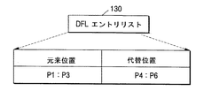
図1Aは、従来の技術によるLOWによる代替を説明するための参考図である。図1Aを参照するに、データ領域100は、ユーザデータ領域110と、少なくとも一つのスペア領域120とを備える。データは、ユーザデータ領域100の開始アドレスから記録される。図1Aに示されたように、媒体上のユーザデータ領域100の物理的空間P1,P2,P3には、既にデータブロックA1,A2,A3が記録されている状態でホストがA1,A2,A3をB1,B2,B3にLOWによってアップデートしようとして、元来位置P1,P2,P3に記録命令を下せば、ドライブシステムは、LOWによる代替によって媒体上のユーザデータ領域110内にあるP4,P5,P6にB1,B2,B3をアップデートし、その代替された状態を表すためにP1,P2,P3がP4,P5,P6に代替された状態を表すDFL(Defect List)エントリ130を図1Bに示したように生成する。
FIG. 1A is a reference diagram for explaining an alternative to LOW according to the prior art. Referring to FIG. 1A, the data area 100 includes a user data area 110 and at least one spare area 120. Data is recorded from the start address of the user data area 100. As shown in FIG. 1A, the physical spaces P1, P2, and P3 of the user data area 100 on the medium are already recorded with data blocks A1, A2, and A3, and the hosts are A1, A2, and A3. If the recording command is originally issued to the positions P1, P2, and P3 in order to update the data to B1, B2, and B3 by LOW, the drive system replaces P4, P5 in the user data area 110 on the medium by the LOW replacement. , P6 is updated with B1, B2, and B3, and a DFL (Defect List)
今後、ホストがデータB1,B2,B3を読み取るために元来位置に該当する論理アドレスで再生命令を下せば、ドライブシステムは、前記DFLエントリ130から媒体上のP4,P5,P6に記録されたデータを再生してホストに伝送する。もし、この時にP4,P5,P6を再生できなければ、代替位置であるP4,P5,P6がユーザデータ領域110にあるので、元来位置のデータと同一であると見なせないので、ドライブシステムは、続けてP4,P5,P6を再生するために再び試みるか、それでも再生できなければ、再生できないとホストに報告する。
In the future, if the host issues a playback command at the logical address corresponding to the original position in order to read the data B1, B2, B3, the drive system is recorded from the
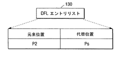
図1Cは、従来の技術による欠陥による代替を説明するための参考図である。図1Cを参照するに、データ領域100は、ユーザデータ領域110と少なくとも一つのスペア領域120とを備える。データはまた、ユーザデータ領域110の開始アドレスから記録される。図1Cに示されたように、ホストが媒体上の元来位置P1,P2,P3に該当する論理アドレスにデータA1,A2,A3を記録するために記録命令を下した時に、ドライブシステムがその論理アドレスに該当する媒体上のユーザデータ領域110の物理アドレスP1,P2,P3に前記データA1,A2,A3を記録する途中に物理ブロックP2が欠陥として発見されて、A2をスペア領域120のPsに代替して記録し、その代替された状態を表すために、DFLエントリ130に(P2→Ps)を図1Dに示されたように生成する。
FIG. 1C is a reference diagram for explaining replacement by a defect according to a conventional technique. Referring to FIG. 1C, the data area 100 includes a user data area 110 and at least one spare area 120. Data is also recorded from the start address of the user data area 110. As shown in FIG. 1C, when the host issues a recording command to record data A1, A2, A3 at logical addresses corresponding to the original positions P1, P2, P3 on the medium, the drive system During the recording of the data A1, A2, A3 in the physical addresses P1, P2, P3 of the user data area 110 on the medium corresponding to the logical address, the physical block P2 is found as a defect, and A2 is detected as Ps in the spare area 120. (P2 → Ps) is generated in the
今後、ホストがA2を再生するために、元来位置P2に該当する論理アドレスに再生命令を下せば、ドライブシステムは、前記DFLエントリ130からその論理アドレスに該当する媒体上の物理アドレスP2がスペア領域のPsに代替されているということが分かり、Psを再生してデータA2をホストに伝送する。もし、Psを再生する途中に、欠陥のような理由によってそのデータを再生できない場合に、ドライブシステムは、前記Psがスペア領域120内にある代替ブロックであることによって、元来ブロックにあるデータもやはりA2であるということが分かるため、たとえPs位置のデータブロックA2を再生できないとしても、前記DFLエントリから元来ブロックに該当するP2位置のデータブロックA2の再生のために試みをさらに行えるという長所を有する。このとき、もし、P2位置のデータブロックA2がエラー訂正可能ならば、そのデータをホストに伝送できるという利点を有する。
In the future, if the host issues a playback command to the logical address corresponding to the original position P2 in order to reproduce A2, the drive system reads the physical address P2 on the medium corresponding to the logical address from the
一方、ディスクの容量を最大限活用して、LOWによる代替と欠陥による代替とを区分して管理するために、LOWによる代替領域と欠陥発生による代替領域とを区分して使用する方法が注目されている。すなわち、欠陥による代替は、既存の欠陥代替のために割り当てたスペア領域に限定し、LOWによる代替は、スペア領域ではないデータ領域のユーザデータ領域、またはユーザデータ領域内の特定領域に代替する方法である。これにより、代替ブロックが欠陥による代替であるか、あるいはLOWによる代替であるかをDFLエントリ(“欠陥エントリ”または“欠陥/代替エントリ”とも呼ばれる)内の代替ブロックが記録された領域を判別することによって分かる。 On the other hand, in order to make maximum use of the capacity of the disc and to manage the replacement by LOW and the replacement by defect, the method of using the replacement area by the LOW and the replacement area by the occurrence of the defect is attracting attention. ing. In other words, replacement by defect is limited to a spare area allocated for replacement of an existing defect, and replacement by LOW is a method of replacing a user data area that is not a spare area or a specific area in the user data area It is. Thereby, it is determined whether the replacement block in the DFL entry (also referred to as “defect entry” or “defect / replacement entry”) is recorded, whether the replacement block is a replacement by a defect or a replacement by a LOW. I understand.
追記型情報記録媒体において、その欠陥による代替ブロック内のユーザデータは、代替前ブロック内のユーザデータと同一である。しかし、LOWによる代替は、主にデータをアップデートするための用途であるため、代替ブロックのユーザデータと代替前ブロックのユーザデータとが同じであると保証できない。もし、DFLエントリの代替ブロックがスペア領域にあれば、これは、欠陥によって発生したDFLエントリであるということが分かり、それで、元来ブロック内のユーザデータと代替ブロック内のユーザデータとが同一であるということが分かる。これにより、代替ブロックを再生時に欠陥によってエラー訂正できないならば、前記DFLエントリの元来ブロックを再生してユーザデータが得られるという長所を有しうる。もちろん、元来ブロックが欠陥によって代替されたため、エラー訂正が不可な場合もあるが、場合によっては、媒体の記録面に付いているホコリのようなエラー要素の除去によってエラー訂正されることもあるためである。 In the write-once information recording medium, the user data in the replacement block due to the defect is the same as the user data in the pre-substitution block. However, since the replacement by LOW is mainly used for updating data, it cannot be guaranteed that the user data of the replacement block and the user data of the block before replacement are the same. If the replacement block of the DFL entry is in the spare area, this indicates that this is a DFL entry caused by a defect, so that the user data in the original block and the user data in the replacement block are the same. I understand that there is. Accordingly, if an error cannot be corrected due to a defect when a substitute block is played back, user data can be obtained by playing back the original block of the DFL entry. Of course, the error may not be corrected because the original block was replaced by a defect, but in some cases, the error may be corrected by removing error elements such as dust on the recording surface of the medium. Because.
このような背景のように、欠陥による代替とLOWによる代替とを区分する理由は、代替ブロック内のユーザデータが元来位置のユーザデータと同一か否かを区分するためであるが、前記背景では、その二つのDFLエントリ内の代替ブロックが記録された領域を区分することによって、これを区分しようとした。 As described above, the reason for distinguishing between substitution by defect and substitution by LOW is to distinguish whether the user data in the substitution block is the same as the user data at the original position. In this case, an attempt is made to distinguish this by partitioning the area in which the replacement blocks in the two DFL entries are recorded.
しかし、LOWによる代替中に欠陥が発生した場合に、そのLOWによる代替ブロックは、再び代替されねばならない。すなわち、言い換えれば、元来ブロックがLOWによる代替ブロックを経て、再び欠陥による代替ブロックに最終スペア領域に代替されることもある。これにより、元来ブロック及び最終代替ブロックのユーザデータは、中間のLOWによる代替によって相互同一でないこともある。したがって、たとえ、代替ブロックがスペア領域にあるとしても、元来ブロックとそのユーザデータとが同じであるという保証はできない。 However, if a defect occurs during LOW replacement, the LOW replacement block must be replaced again. That is, in other words, the original block may be replaced with the final spare area again by the replacement block due to the defect after passing through the replacement block due to LOW. As a result, the user data of the original block and the final replacement block may not be identical to each other due to the intermediate LOW replacement. Therefore, even if the replacement block is in the spare area, it cannot be guaranteed that the original block and its user data are the same.
したがって、データ使用を最大化し、データ再生効率を向上させるために、代替ブロックのユーザデータが元来ブロックのユーザデータと同一になるように保証する必要がある。 Therefore, in order to maximize data use and improve data reproduction efficiency, it is necessary to ensure that the user data of the alternative block is the same as the user data of the original block.
本発明が解決しようとする課題は、前記問題点を解決して、LOWによる代替のための代替領域と欠陥による代替のための代替領域とが区分されるシステムで、データ再生の効率を向上させうる情報記録媒体、記録/再生装置及び記録/再生方法を提供することである。 The problem to be solved by the present invention is to solve the above problems and improve the efficiency of data reproduction in a system in which a replacement area for replacement by LOW and a replacement area for replacement by a defect are separated. An information recording medium, a recording / reproducing apparatus, and a recording / reproducing method are provided.
前記課題を解決するための本発明の一つの特徴は、情報記録媒体において、前記媒体には、前記媒体に記録されたデータのアップデートのためのLOWによる代替のための第1領域と、前記媒体に発生した欠陥を代替するための第2領域とが設けられ、前記媒体の所定領域に記録された元来ブロックのLOWのために、前記第1領域に第1代替ブロックを代替する途中に欠陥が発生した場合に、前記第1代替ブロックの欠陥による代替のための第2代替ブロックは、前記第2領域に設けられ、前記代替状態を表すためのDFLエントリは、前記元来ブロックの位置情報と前記第2代替ブロックの位置情報とを含んでおり、前記第2代替ブロックは、前記第1代替ブロックの位置情報を含んでいることである。 One feature of the present invention for solving the above problem is that in the information recording medium, the medium includes a first area for replacement by LOW for updating data recorded on the medium, and the medium. And a second area for substituting the defect generated in the medium, and the defect is in the process of substituting the first replacement block for the first area for the LOW of the original block recorded in the predetermined area of the medium. Is generated, a second replacement block for replacement due to a defect of the first replacement block is provided in the second area, and the DFL entry for indicating the replacement state includes position information of the original block. And the position information of the second substitute block, and the second substitute block includes the position information of the first substitute block.
前記第2代替ブロックは、記録または再生単位ブロックであり、前記記録または再生単位ブロックは、ユーザデータのためのユーザデータ部分と前記第1代替ブロックの位置情報のための付加情報部分とで形成されることが望ましい。 The second substitution block is a recording or reproduction unit block, and the recording or reproduction unit block is formed of a user data portion for user data and an additional information portion for position information of the first substitution block. It is desirable.
前記付加情報部分は、前記ユーザデータ部分よりエラー訂正能力に優れるように記録されることが望ましい。 The additional information part is preferably recorded so as to have better error correction capability than the user data part.
前記元来ブロックの位置情報と前記第2代替ブロックの位置情報とは、前記媒体の物理的空間上のアドレスで表示されることが望ましい。 The original block position information and the second substitute block position information are preferably displayed by addresses in the physical space of the medium.
本発明の他の特徴は、情報記録媒体において、前記媒体には、前記媒体に記録されたデータのアップデートのためのLOWによる代替のための第1領域と、前記媒体に発生した欠陥を代替するための第2領域とが設けられ、前記媒体の所定領域に記録された元来ブロックのLOWのために、前記第1領域に第1代替ブロックを代替する途中に欠陥が発生した場合に、前記第1代替ブロックの欠陥による代替のための第2代替ブロックは、前記第2領域に設けられ、前記LOWによる代替状態を表すための第1 DFLエントリと、前記LOWによる代替途中に発生した欠陥による代替状態を表すための第2 DFLエントリとが設けられることである。 According to another aspect of the present invention, in the information recording medium, the medium replaces a first area for replacement by LOW for updating data recorded on the medium, and a defect generated in the medium. And a second area is provided, and when a defect occurs during replacement of the first substitute block in the first area due to the LOW of the original block recorded in the predetermined area of the medium, A second replacement block for replacement due to a defect in the first replacement block is provided in the second area, and includes a first DFL entry for representing a replacement state by the LOW, and a defect generated during replacement by the LOW. And a second DFL entry for representing an alternative state.
前記第1 DFLエントリは、前記元来ブロックの位置情報と前記第1代替ブロックの位置情報とを含んでおり、前記第2 DFLエントリは、前記第1代替ブロックの位置情報と前記第2代替ブロックの位置情報とを含んでいることが望ましい。 The first DFL entry includes position information of the original block and position information of the first replacement block, and the second DFL entry includes position information of the first replacement block and the second replacement block. It is desirable to include the position information.
前記第1 DFLエントリは、前記第1 DFLエントリに関連した前記第1代替ブロックが前記第2代替ブロックに代替されたことを表すためのリンク状態情報をさらに含んでいることが望ましい。 The first DFL entry may further include link state information for indicating that the first replacement block associated with the first DFL entry is replaced with the second replacement block.
前記第1領域は、ユーザデータ領域であり、前記第2領域は、スペア領域であることが望ましい。 The first area may be a user data area, and the second area may be a spare area.
本発明のさらに他の特徴は、情報記録媒体において、前記媒体には、前記媒体に記録されたデータのアップデートのためのLOWによる代替がユーザデータ領域でなされ、前記代替状態を表すためのDFLエントリは、前記元来ブロックの位置情報と前記代替ブロックの位置情報とを含んでおり、論理的に記録されていない空間への記録命令による前記空間が物理的には記録された空間である場合に、前記DFLエントリの前記代替ブロックの位置情報は、他のDFLエントリの元来ブロックの位置情報となることが許容されることである。 According to another aspect of the present invention, there is provided an information recording medium, wherein the medium is provided with a LOW replacement for updating data recorded on the medium in a user data area, and a DFL entry for representing the replacement state Includes the position information of the original block and the position information of the alternative block, and when the space by the recording command to the space not logically recorded is a physically recorded space The position information of the substitute block of the DFL entry is allowed to be the position information of the original block of another DFL entry.
本発明のさらに他の特徴は、記録/再生装置において、情報記録媒体に/からデータを書き込み/読み取りする書き込み/読み取り部と、前記媒体に記録されたブロックのアップデートのためのLOWによる代替ブロックを前記媒体の第1領域に記録し、前記媒体に発生した欠陥ブロックを代替するための代替ブロックを前記媒体の第2領域に記録し、前記媒体の所定領域に記録された元来ブロックのLOWのために、前記第1領域に第1代替ブロックを代替する途中に欠陥が発生した場合に、前記第1代替ブロックの欠陥による代替のための第2代替ブロックを前記第2領域に記録するように前記書き込み/読み取り部を制御し、前記代替状態を表すために、前記元来ブロックの位置情報と前記第2代替ブロックの位置情報とを含んでいるDFLエントリと、を生成し、前記第2代替ブロックには、前記第1代替ブロックの位置情報を配列することである。 According to still another aspect of the present invention, in the recording / reproducing apparatus, a writing / reading unit for writing / reading data to / from an information recording medium, and an alternative block by LOW for updating a block recorded on the medium Recording in the first area of the medium, recording a replacement block for replacing the defective block generated in the medium in the second area of the medium, and the LOW of the original block recorded in the predetermined area of the medium Therefore, when a defect occurs in the first area while substituting the first replacement block, a second replacement block for replacement due to the defect of the first replacement block is recorded in the second area. In order to control the writing / reading unit and to represent the substitution state, the original block position information and the second substitution block position information are included. And FL entry to generate, in the second replacement block is to arrange the position information of the first replacement block.
本発明のさらに他の特徴は、記録/再生装置において、情報記録媒体に/からデータを書き込み/読み取りする書き込み/読み取り部と、前記媒体に記録されたブロックのアップデートのためのLOWによる代替ブロックを前記媒体の第1領域に記録し、前記媒体に発生した欠陥ブロックを代替するための代替ブロックを前記媒体の第2領域に記録し、前記媒体の所定領域に記録された元来ブロックのLOWのために、前記第1領域に第1代替ブロックを代替する途中に欠陥が発生した場合に、前記第1代替ブロックの欠陥による代替のための第2代替ブロックを前記第2領域に記録するように前記書き込み/読み取り部を制御し、前記LOWによる代替状態を表すための第1 DFLエントリと、前記LOWによる代替途中に発生した欠陥による代替状態を表すための第2 DFLエントリとを生成する制御部とを備えることである。 According to still another aspect of the present invention, in the recording / reproducing apparatus, a writing / reading unit for writing / reading data to / from an information recording medium, and an alternative block by LOW for updating a block recorded on the medium Recording in the first area of the medium, recording a replacement block for replacing the defective block generated in the medium in the second area of the medium, and the LOW of the original block recorded in the predetermined area of the medium Therefore, when a defect occurs in the first area while substituting the first replacement block, a second replacement block for replacement due to the defect of the first replacement block is recorded in the second area. A first DFL entry for controlling the writing / reading unit and representing the substitution state by the LOW, and a defect that occurred during the substitution by the LOW It is provided with a control unit generating a first 2 DFL entry for indicating the replacement state with.
本発明のさらに他の特徴は、記録/再生装置において、情報記録媒体に/からデータを書き込み/読み取りする書き込み/読み取り部と、前記媒体に記録されたデータのアップデートのためのLOWによる代替データをユーザデータ領域に記録するように前記書き込み/読み取り部を制御し、前記代替状態を表すために、前記元来ブロックの位置情報と前記代替ブロックの位置情報とを含んでいるDFLエントリを生成し、論理的に記録されていない空間への記録命令による前記空間が物理的には記録された空間である場合に、前記DFLエントリの前記代替ブロックの位置情報は、他のDFLエントリの元来ブロックの位置情報となることを許容する制御部とを備えることである。 Still another feature of the present invention is that in a recording / reproducing apparatus, a writing / reading unit for writing / reading data to / from an information recording medium, and substitute data by LOW for updating data recorded on the medium Controlling the writing / reading unit to record in a user data area, and generating a DFL entry including the original block position information and the replacement block position information to represent the replacement state; When the space by the recording command to the space that is not logically recorded is a physically recorded space, the position information of the alternative block of the DFL entry is the original block of the other DFL entry. And a control unit that allows position information to be obtained.
本発明のさらに他の特徴は、記録/再生方法において、情報記録媒体に記録されたブロックのアップデートのためのLOWによる代替ブロックを前記媒体の第1領域に記録し、前記媒体に発生した欠陥ブロックを代替するための代替ブロックを前記媒体の第2領域に記録するステップと、前記媒体の所定領域に記録された元来ブロックのLOWのために、前記第1領域に第1代替ブロックを代替する途中に欠陥が発生した場合に、前記第1代替ブロックの欠陥による代替のための第2代替ブロックに前記第1代替ブロックの位置情報を配列して前記第2領域に記録するステップと、前記代替状態を表すために、前記元来ブロックの位置情報と前記第2代替ブロックの位置情報とを含んでいるDFLエントリを生成するステップとを含むことである。 According to another aspect of the present invention, in the recording / reproducing method, a LOW substitute block for updating a block recorded on an information recording medium is recorded in the first area of the medium, and a defective block generated in the medium is recorded. A replacement block for replacing the first replacement block in the first area for recording a replacement block in the second area of the medium and LOW of the original block recorded in the predetermined area of the medium The step of arranging the position information of the first replacement block in the second replacement block for replacement by the defect of the first replacement block and recording it in the second area when a defect occurs in the middle; and the replacement Generating a DFL entry that includes the position information of the original block and the position information of the second alternative block to represent a state, That.
本発明のさらに他の特徴は、記録/再生方法において、情報記録媒体に記録されたブロックのアップデートのためのLOWによる代替ブロックを前記媒体の第1領域に記録し、前記媒体に発生した欠陥ブロックを代替するための代替ブロックを前記媒体の第2領域に記録し、前記媒体の所定領域に記録された元来ブロックのLOWのために、前記第1領域に第1代替ブロックを代替する途中に欠陥が発生した場合に、前記第1代替ブロックの欠陥による代替のための第2代替ブロックを前記第2領域に記録するステップと、前記LOWによる代替状態を表すための第1 DFLエントリと、前記LOWによる代替途中に発生した欠陥による代替状態を表すための第2 DFLエントリとを生成するステップとを含むことである。 According to another aspect of the present invention, in the recording / reproducing method, a LOW substitute block for updating a block recorded on an information recording medium is recorded in the first area of the medium, and a defective block generated in the medium is recorded. In the middle of substituting the first substitute block in the first area for the LOW of the original block recorded in the predetermined area of the medium. When a defect occurs, recording a second replacement block for replacement by a defect of the first replacement block in the second area; a first DFL entry for representing a replacement state by the LOW; and Generating a second DFL entry for representing a replacement state due to a defect that occurred during replacement by LOW.
本発明のさらに他の特徴は、記録/再生方法において、情報記録媒体に記録されたデータのアップデートのためのLOWによる代替データをユーザデータ領域に記録するステップと、前記代替状態を表すために、前記元来ブロックの位置情報と前記代替ブロックの位置情報とを含んでいるDFLエントリを生成するステップと、論理的に記録されていない空間への記録命令による前記空間が物理的には記録された空間である場合に、前記DFLエントリの前記代替ブロックの位置情報は、他のDFLエントリの元来ブロックの位置情報となることを許容するステップと、を含むことである。 According to still another aspect of the present invention, in the recording / reproducing method, the step of recording the LOW substitute data for updating the data recorded in the information recording medium in the user data area; A step of generating a DFL entry including the position information of the original block and the position information of the substitute block, and the space is physically recorded by a recording command to a space that is not logically recorded. If it is a space, the location information of the alternative block of the DFL entry is allowed to be the location information of the original block of another DFL entry.
本発明のさらに他の特徴は、データ再生装置において、情報記録媒体からデータを読み取る読み取り部と、再生しようとするデータに関するDFLエントリに含まれた代替位置情報によって、その位置にある代替ブロックを読み取るように前記読み取り部を制御し、前記読み取られた代替ブロックのエラー訂正が失敗した場合に、前記代替ブロックに含まれた付加情報部分から以前代替ブロックの位置を確認し、前記以前代替ブロックの位置から代替ブロックを読み取るように前記読み取り部を制御して、前記読み取られた代替ブロックを再生する制御部と、を備えることである。 Still another feature of the present invention is that in the data reproducing apparatus, the substitute block at the position is read by the reading unit that reads data from the information recording medium and the substitute position information included in the DFL entry related to the data to be reproduced. If the error correction of the read substitute block fails, the position of the previous substitute block is confirmed from the additional information part included in the substitute block when the error correction of the read substitute block fails. And a control unit that controls the reading unit to read the alternative block from the reproduction unit and reproduces the read alternative block.
本発明のさらに他の特徴は、データ再生装置において、情報記録媒体からデータを読み取る読み取り部と、再生しようとするデータに関する第1 DFLエントリにリンク状態情報が設定されている場合に、前記第1 DFLエントリにリンクされた第2 DFLエントリに含まれた代替位置情報によって、その位置にある代替ブロックを読み取るように前記読み取り部を制御し、前記読み取られた代替ブロックの再生が失敗した場合に、前記第1 DFLエントリに含まれた代替位置情報によってその位置にある代替ブロックを読み取るように前記読み取り部を制御し、前記読み取られた代替ブロックを再生する制御部と、を備えることである。 According to still another aspect of the present invention, in the data reproducing apparatus, when the link state information is set in the reading unit that reads data from the information recording medium and the first DFL entry related to the data to be reproduced, When the reading unit is controlled to read the substitute block at the position according to the substitute position information included in the second DFL entry linked to the DFL entry, and the reproduction of the read substitute block fails, And a control unit that controls the reading unit to read the substitute block at the position based on the substitute position information included in the first DFL entry, and reproduces the read substitute block.
本発明のさらに他の特徴は、データ再生方法において、再生しようとするデータに関するDFLエントリに含まれた代替位置情報によって、その位置にある代替ブロックを読み取るステップと、前記読み取られた代替ブロックのエラー訂正が失敗した場合に、前記代替ブロックに含まれた付加情報部分から以前代替ブロックの位置を確認するステップと、前記以前代替ブロックの位置から代替ブロックを読み取って前記読み取られた代替ブロックを再生するステップとを含むことである。 According to still another aspect of the present invention, in the data reproduction method, the step of reading the substitute block at the position by the substitute position information included in the DFL entry relating to the data to be played back, and the error of the read substitute block When the correction fails, the step of confirming the position of the previous replacement block from the additional information part included in the replacement block, and reading the replacement block from the position of the previous replacement block and reproducing the read replacement block Steps.
本発明のさらに他の特徴は、データ再生方法において、再生しようとするデータに関する第1 DFLエントリにリンク状態情報が設定されている場合に、前記第1 DFLエントリにリンクされた第2 DFLエントリに含まれた代替位置情報によって、その位置にある代替ブロックを読み取るステップと、前記読み取られた代替ブロックの再生が失敗した場合に、前記第1 DFLエントリに含まれた代替位置情報によって、その位置にある代替ブロックを読み取り、前記読み取られた代替ブロックを再生するステップとを含むことである。 According to still another aspect of the present invention, in the data reproduction method, when link state information is set in the first DFL entry related to the data to be reproduced, the second DFL entry linked to the first DFL entry is provided. The step of reading the substitute block at the position by the included substitute position information, and when the reproduction of the read substitute block fails, the substitute position information contained in the first DFL entry Reading a substitute block and reproducing the read substitute block.
本発明によれば、欠陥による代替のための領域とLOWによる代替のための領域とが区分されているシステムで、LOWによる途中欠陥が発生して欠陥による代替がなされた場合にも代替情報を効果的に管理して、データ再生の効率を向上させうる。 According to the present invention, in a system in which an area for replacement by a defect and an area for replacement by a LOW are separated, replacement information is also provided when an intermediate defect by LOW occurs and replacement by a defect is made. It can be effectively managed to improve the efficiency of data reproduction.
以下、添付された図面を参照して本発明を詳細に説明する。 Hereinafter, the present invention will be described in detail with reference to the accompanying drawings.
本発明は、LOWによる代替途中に発生した欠陥の代替のために、2つの方法を提示する。 The present invention presents two methods for substituting defects that occurred during replacement by LOW.
第1の方法は、LOWのための代替中に発生した欠陥に対しては、欠陥発生時に代替のために設けたスペア領域に代替を行い、1)その代替状態を表すためのDFLエントリは、元来ブロックが最終代替ブロックに代替されたということを表すように生成し、2)代替ブロック内の付加情報には、代替直前のブロックの位置情報を含める。例えば、ユーザデータ領域内にある元来ブロックAが、LOWによってユーザデータ領域内にある中間代替ブロックBに代替する途中に、中間代替ブロックBが記録エラーまたは記録後検証のような方法によって欠陥と判断されれば、スペア領域内にある最終代替ブロックCに代替し、DFLエントリは、元来ブロックAが最終代替ブロックCに代替されたということを表すように生成し、最終代替ブロックCの付加情報には、中間代替ブロックBの位置情報を保存する。そして、中間代替ブロックBの付加情報には、元来ブロックAの位置情報を保存する。 In the first method, for a defect generated during replacement for LOW, a spare area provided for replacement is replaced when a defect occurs, and 1) a DFL entry for representing the replacement state is: It is generated so as to indicate that the original block has been replaced with the final replacement block. 2) The additional information in the replacement block includes the position information of the block immediately before the replacement. For example, while the original block A in the user data area is replaced by the intermediate replacement block B in the user data area by LOW, the intermediate replacement block B is detected as defective by a method such as recording error or post-recording verification. If it is determined, it is replaced with the final replacement block C in the spare area, and the DFL entry is generated so as to indicate that the original block A is replaced with the final replacement block C. In the information, the position information of the intermediate substitute block B is stored. Then, the position information of the block A is originally stored in the additional information of the intermediate replacement block B.
これにより、今後、スペア領域内の最終代替ブロックCを再生しようとする時に、もし、最終代替ブロックCが欠陥のような原因によって再生できない場合、ドライブシステムは、前記最終代替ブロックC内の付加情報に保存されている位置情報を見て、その位置情報がユーザデータ領域内の位置情報ならば、その位置に該当する中間代替ブロックBが欠陥によって最終代替ブロックCに代替されて、二つのブロック内のユーザデータが同一であるということが分かって、ユーザデータ領域内にある中間代替ブロックBを再生しうる。 As a result, when the final substitute block C in the spare area is to be reproduced in the future, if the final substitute block C cannot be reproduced due to a cause such as a defect, the drive system performs additional information in the final substitute block C. If the position information is the position information in the user data area, the intermediate replacement block B corresponding to the position is replaced by the final replacement block C due to the defect, and the two in the block Thus, the intermediate substitute block B in the user data area can be reproduced.
たとえ、記録/再生ブロック内のユーザデータがエラー訂正不可であるとしても、その記録/再生ブロック内の保存されている付加情報が分かるためには、ブルーレイのように、その付加情報のためのエラー訂正ブロックのエラー訂正能力がユーザデータのためのエラー訂正ブロックのエラー訂正能力より卓越した構造であることが望ましい。現在のブルーレイのECC(Error Correction Code)フォーマットは、ユーザデータのためのLDC(Long Distance Code)クラスターと付加情報のためのBIS(Burst Indicator Subcode)クラスターとで構成されて、ユーザデータと付加情報とが異なるエラー訂正ブロックで構成されている。そして、前記BISクラスターは、(62,30,32)RS(Reed Solomon)コードからなり、LDCクラスターは、(248,216,32)RSドードで構成されており、BISクラスターのエラー訂正能力が卓越して、たとえユーザデータのためのLDCクラスターをエラー訂正できないとしても、大慨の場合に、BISクラスターは、エラー訂正可能な構造である。 Even if user data in the recording / playback block cannot be corrected, in order to know the additional information stored in the recording / playback block, an error for the additional information, such as Blu-ray, can be obtained. It is desirable that the error correction capability of the correction block is superior to the error correction capability of the error correction block for user data. The current Blu-ray ECC (Error Correction Code) format is composed of an LDC (Long Distance Code) cluster for user data and a BIS (Burst Indicator Subcode) cluster for additional information. Are composed of different error correction blocks. The BIS cluster is composed of (62, 30, 32) RS (Reed Solomon) code, and the LDC cluster is composed of (248, 216, 32) RS dodo, and the error correction capability of the BIS cluster is outstanding. Thus, even if the LDC cluster for user data cannot be error-corrected, the BIS cluster is an error-correctable structure in the first case.
第2の方法は、LOWのための代替の間に発生した欠陥に対しては、欠陥発生時に代替のために設けたスペア領域に代替を行い、その代替状態を表すために元来ブロックがLOWによって代替された代替ブロック(欠陥の発生したブロック)に代替され、また、他のDFLエントリに連結されていることを表す状態情報を含むDFLエントリと、前記LOWによって代替された代替ブロック(欠陥の発生したブロック)が最終代替ブロックに代替されたということを表すDFLエントリ(このDFLエントリは、前記DFLエントリと連結されているという状態情報を含むこともある)とを生成する。 In the second method, for a defect that occurs during replacement for LOW, a spare area provided for replacement is replaced when the defect occurs, and the original block is LOW to indicate the replacement state. A DFL entry that includes status information indicating that it is replaced with a replacement block (a defective block) replaced by another DFL entry and that is connected to another DFL entry, and a replacement block (a defective block) replaced with the LOW. A DFL entry indicating that the generated block) has been replaced by the final replacement block (this DFL entry may include state information that is linked to the DFL entry).
このような第2の方法で、二つまたはそれ以上のDFLエントリが連結されている状態は、次のような方法によって分かる。ホストがあるブロック内の一部セクターまたはブロック全体を再生しようとすれば、ドライブシステムは、そのホストの命令に該当する物理的な位置が他の領域に代替されたかを、DFLエントリを検索することによって判別する。もし、あるDFLエントリからそのDFLエントリのリンク状態情報を見て、リンク状態情報が設定されていないならば、そのまま前記DFLエントリの代替ブロックを再生し、リンク状態情報が設定されているならば、前記DFLエントリの代替ブロックに該当するブロックが元来ブロックに設定されている他のDFLエントリを探して、そのDFLエントリの代替ブロックを再生する。すなわち、第2の方法は、LOWによるDFLエントリと欠陥によるDFLエントリとを区別する。もし、LOWによる代替中に欠陥が発生する場合においては、LOWによるDFLエントリと欠陥によるDFLエントリとに区分し、その連結状態情報を前記少なくともLOWによるDFLエントリに表す。すなわち、LOWによるDFLエントリは、元来ブロックAが中間代替ブロックBに代替されているということと、このDFLエントリが他のDFLエントリによって連結されているという状態情報とを表し、欠陥によるDFLエントリは、中間代替ブロックBが最終代替ブロックCに代替されているということを表す。 The state in which two or more DFL entries are linked in the second method can be understood by the following method. If the host tries to reproduce a sector or the entire block in a block, the drive system searches the DFL entry to find out if the physical location corresponding to the host command has been replaced by another area. Determine by. If the link status information of the DFL entry is viewed from a certain DFL entry and the link status information is not set, the substitute block of the DFL entry is reproduced as it is, and if the link status information is set, A block corresponding to the substitute block of the DFL entry is searched for another DFL entry in which the block is originally set, and the substitute block of the DFL entry is reproduced. That is, the second method distinguishes between a DFL entry due to LOW and a DFL entry due to a defect. If a defect occurs during replacement by LOW, it is divided into a DFL entry by LOW and a DFL entry by defect, and the connection state information is represented by at least the DFL entry by LOW. That is, the DFL entry by LOW indicates that the original block A is replaced by the intermediate replacement block B, and the state information that this DFL entry is connected by another DFL entry, and the DFL entry by the defect Represents that the intermediate replacement block B is replaced by the final replacement block C.
これにより、データ再生時にホストが元来ブロックAを再生するためにドライブシステムに命令すれば、ドライブシステムは、元来ブロックAを元来アドレスとして有しているDFLエントリを探して、元来アドレス(元来ブロックA)が代替されている代替アドレス(中間代替ブロックB)を探し、また、リンク状態情報を確認した後に設定されていれば、その代替アドレス(中間代替ブロックB)を元来アドレスとして有しているDFLエントリを探して、その元来アドレス(中間代替ブロックB)が代替されている代替アドレス(最終代替ブロックC)を再生してホストに伝送する。もし、このスペア領域内にある最終代替ブロックCを再生する途中に、欠陥のような原因によってそのユーザデータを再生できない場合には、その最終代替ブロックCがスペア領域内にあることによって、それが欠陥によって代替された代替ブロックであることが分かり、また、前記DFLエントリの元来アドレス(中間代替ブロックB)内にあるユーザデータが同一であるということが分かるので、前記中間代替ブロックBを接近して再生できる。 Thus, if the host instructs the drive system to reproduce the original block A during data reproduction, the drive system searches for the DFL entry having the original block A as the original address, and the original address. Look for an alternative address (intermediate alternative block B) in which (original block A) is replaced, and if it is set after checking the link status information, the alternative address (intermediate alternative block B) is the original address. Is searched for, and the substitute address (final substitute block C) in which the original address (intermediate substitute block B) is substituted is reproduced and transmitted to the host. If the user data cannot be reproduced due to a cause such as a defect during the reproduction of the final substitute block C in the spare area, the fact that the final substitute block C is in the spare area Since it is known that the replacement block is replaced by a defect and the user data in the original address (intermediate replacement block B) of the DFL entry is the same, the intermediate replacement block B is approached. Can be played.
整理すれば、追記型情報記録媒体において、その欠陥による代替ブロック内のユーザデータと欠陥ブロック内のユーザデータとが同じであるため、LOWによる代替と欠陥による代替とを領域で区分する場合に、代替ブロックがどの領域にあるかを判断することによって、その代替が欠陥によるものか否か、すなわち、代替されたユーザデータの内容が代替以前のユーザデータの内容と同一か否かを区分できる。LOWによる代替中に欠陥が発生して再び代替が起きる場合にも、前記のような利点を維持するために、本発明は、LOWによる代替途中に欠陥が発生すれば、欠陥のためのスペア領域に代替し、DFLエントリは、元来ブロックが最終代替ブロックに代替されたということを表し、また、代替ブロック内に以前代替ブロックの位置情報を保存する第1の方法と、LOWによる代替途中に欠陥が発生すれば、欠陥のためのスペア領域に代替し、また、LOWによる代替状態を表すためのDFLエントリと欠陥による代替状態を表すためのDFLエントリとを区分して表し、DFLエントリにそのリンク状態情報を含める第2の方法とを提示する。 To summarize, in the write-once type information recording medium, the user data in the replacement block due to the defect and the user data in the defect block are the same. By determining in which area the replacement block is located, it is possible to distinguish whether the replacement is due to a defect, that is, whether the content of the replaced user data is the same as the content of the user data before the replacement. In order to maintain the above advantages even when a defect occurs during replacement by LOW and replacement occurs again, the present invention provides a spare area for a defect if a defect occurs during replacement by LOW. The DFL entry indicates that the original block has been replaced by the final replacement block, and the first method of storing the position information of the previous replacement block in the replacement block, and during the replacement by LOW If a defect occurs, it is replaced with a spare area for the defect, and a DFL entry for representing a substitute state due to LOW and a DFL entry for representing a substitute state due to the defect are separately represented. A second method for including link state information is presented.
図2は、本発明による記録/再生装置の概略図である。図2を参照するに、本実施形態による記録/再生装置200は、記録または再生の可能な装置であって、書き込み/読み取り部220及び制御部210を備える。記録/再生装置200は、全体的にまたは部分的に内部(すなわち、ホスト240内にハウジングされる)または外部(ホスト240に連結される別途のボックスにハウジングされる)のドライブシステムと言及されうる。
FIG. 2 is a schematic diagram of a recording / reproducing apparatus according to the present invention. Referring to FIG. 2, the recording / reproducing
書き込み/読み取り部220は、制御部210の制御によって、本実施形態による情報記録媒体であるディスク400に/からデータを書き込み/読み取りする。制御部210は、本発明によってデータを所定記録単位ブロックで記録するように、書き込み/読み取り部220を制御するか、または書き込み/読み取り部220によって読み取られたデータを処理して有効なデータを得る。
The writing /
記録時に、制御部210は、特に本発明によって、ホストの命令によって、またはドライブシステム自体の制御によって、LOWを具現してデータを記録するように書き込み/読み取り部220を制御する。LOWは、追記型媒体のユーザデータ領域に記録されたデータをアップデートするために、そのアップデートされた、すなわち、代替データをユーザデータ領域の未記録領域に記録し、ホスト側面から見る論理的アドレスは変わりのないように、元来のデータ及び代替データのアドレス情報を管理すること(これは、DFLエントリに作成し、ディスクに記録することによって行われる)を称す。本発明による制御部210は、このようにLOWによってユーザデータ領域の未記録領域に代替を行う。また、本発明による制御部210は、欠陥による代替のために代替データをスペア領域に記録する。
At the time of recording, the
図3は、図2に示された記録/再生装置構成の細部的なブロック図である。図3を参照するに、記録/再生装置200の制御部210と書き込み/読み取り部220とは、幾つかの異なるコンポーネントで具現されうる。例えば、光ピックアップ250は、光ディスク400に/から記録/再生動作を行うための書き込み/読み取り部220の役割を行える。また、ホストI/F 211、DSP(Digital Signal Processor)212、RF AMP(Radio Frequency Amplifier)213、サーボ214及びシステム制御器215は、制御部210としての役割を行える。言い換えれば、光ピックアップ250とシステム制御器215とは、それぞれ書き込み/読み取り部220と制御部210とに対応する。
FIG. 3 is a detailed block diagram of the recording / reproducing apparatus configuration shown in FIG. Referring to FIG. 3, the
記録時に、ホストI/F 211は、ホスト240から記録するデータと、前記記録するデータの論理的アドレス情報と共に記録命令を受信し、これをシステム制御器215に伝送する。
At the time of recording, the host I /
システム制御器215は、ホストI/F 211から記録命令を受信し、記録に必要な初期化を行う。
The
特に、本発明の第1の方法によって、前記システム制御器215は、前記媒体に記録されたブロックのアップデートのためのLOWによる代替ブロックを前記媒体のユーザデータ領域に記録し、前記媒体に発生した欠陥ブロックを代替するための代替ブロックを前記媒体のスペア領域に記録し、前記媒体の所定領域に記録された元来ブロックのLOWのために、前記ユーザデータ領域に第1代替ブロックを代替する途中に欠陥が発生した場合に、前記第1代替ブロックの欠陥による代替のための第2代替ブロックを前記スペア領域に記録するように前記書き込み/読み取り部を制御し、前記代替状態を表すために、前記元来ブロックの位置情報と前記第2代替ブロックの位置情報とを含んでいる代替エントリ(DFLエントリ)を生成し、前記第2代替ブロックには、前記第1代替ブロックの位置情報を配列する。
In particular, according to the first method of the present invention, the
また、本発明の第2の方法によって、システム制御器215は、前記媒体に記録されたブロックのアップデートのためのLOWによる代替ブロックを前記媒体のユーザデータ領域に記録し、前記媒体に発生した欠陥ブロックを代替するための代替ブロックを前記媒体のスペア領域に記録し、前記媒体の所定領域に記録された元来ブロックのLOWのために、前記ユーザデータ領域に第1代替ブロックを代替する途中に欠陥が発生した場合に、前記第1代替ブロックの欠陥による代替のための第2代替ブロックを前記スペア領域に記録するように前記書き込み/読み取り部を制御し、前記LOWによる代替状態を表すための第1 DFLエントリと、前記LOWによる代替途中に発生した欠陥による代替状態を表すための第2 DFLエントリとを生成する。
Further, according to the second method of the present invention, the
DSP 212は、ホストI/F 211から受けた記録するデータをエラー訂正するためにパリティなどの付加データを添加し、ECCエンコーディングを行って、エラー訂正ブロックであるECCブロックを生成した後、それを既定の方式で変調する。RF AMP 213は、DSP 212から出力されたデータをRF信号に変える。ピックアップ250は、RF AMP 213から出力されたRF信号をディスク230に記録する。サーボ214は、システム制御器215からサーボ制御に必要な命令を入力されてピックアップ250をサーボ制御する。
The
再生時に、ホストI/F 211は、ホスト240から再生命令を受ける。システム制御器215は、再生に必要な初期化を行う。
During reproduction, the host I /
特に、本発明の第1の方法によって、システム制御器215は、再生命令による論理アドレスを物理アドレスに変換し、変換された物理アドレスに基づいてDFLエントリから代替アドレスを探して、その位置にある代替ブロックを読み取り、前記読み取られた代替ブロックのエラー訂正が失敗した場合に、前記代替ブロックに含まれた付加情報部分から以前代替ブロックの位置を確認し、前記以前代替ブロックの位置から代替ブロックを読み取るように前記読み取り部を制御し、前記読み取られた代替ブロックを再生するように制御する。
In particular, according to the first method of the present invention, the
また、本発明の第2の方法によって、システム制御器215は、再生命令による論理アドレスを物理アドレスに変換し、変換された物理アドレスに基づいてDFLエントリを探すが、再生しようとするデータに関する第1 DFLエントリにリンク状態情報が設定されている場合に、前記第1 DFLエントリにリンクされた第2 DFLエントリに含まれた代替位置情報によって、その位置にある代替ブロックを読み取るように前記読み取り部を制御し、前記読み取られた代替ブロックの再生が失敗した場合に、前記第1 DFLエントリに含まれた代替位置情報によって、その位置にある代替ブロックを読み取るように前記読み取り部を制御し、前記読み取られた代替ブロックを再生する。
In addition, according to the second method of the present invention, the
ピックアップ250は、ディスク400にレーザビームを照射し、ディスク400から反射されたレーザビームを受光して得られた光信号を出力する。RF AMP 213は、ピックアップ250から出力された光信号をRF信号に変えて、RF信号から得られた変調されたデータをDSP 212に提供する一方、RF信号から得られた制御のためのサーボ信号をサーボ214に提供する。DSP 212は、変調されたデータを復調し、ECCエラー訂正を経て得られたデータを出力する。
The
一方、サーボ214は、RF AMP 213から受けたサーボ信号とシステム制御器215から受けたサーボ制御に必要な命令とを受けて、ピックアップ250に対するサーボ制御を行う。ホストI/F 211は、DSP 212から受けたデータをホスト240に送る。
On the other hand, the
図4は、本発明による情報記録媒体の構造図である。図4を参照するに、追記型情報記録媒体400に記録されるデータ構造400は、リードイン領域410と、データ領域420と、リードアウト領域430と、を備える。
FIG. 4 is a structural diagram of an information recording medium according to the present invention. Referring to FIG. 4, the
リードイン領域410は、第2ディスク管理領域
411と、臨時ディスク管理領域(Temporary Disc Management Area:TDMA)412、及び第1ディスク管理領域413を備える。前記第1及び第2ディスク管理領域411,413は、データ領域420で発生した一つ以上の欠陥に関する情報を記録するために提供される。対照的に、リードイン領域410、リードアウト領域430は、第3ディスク管理領域431、第4ディスク管理領域432を備え、TDMAは、備えていない。
The lead-in area 410 includes a second disk management area 411, a temporary disk management area (TDMA) 412, and a first disk management area 413. The first and second disk management areas 411 and 413 are provided for recording information on one or more defects generated in the data area 420. In contrast, the lead-in area 410 and the lead-out area 430 include a third disk management area 431 and a fourth disk management area 432, and no TDMA.
リードイン領域410に含まれたTDMA 412は、追記型情報記録媒体の管理のための臨時欠陥管理と臨時ディスク管理とのための情報を記録するための領域と称す。
The
このようなTDMA 412は、臨時欠陥リスト(Temporary Defect List:TDFL)414、臨時ディスク定義構造(Temporary Disc Definition Structure:TDDS)415、記録管理データ(Recording Management Data:RMD)416を備える。
The
TDFL 414は、臨時欠陥に関する情報を表し、欠陥データの位置情報とこの欠陥データを代替する代替データの位置情報とを含む。特に、本発明によってTDFLは、欠陥発生による代替状態またはLOWによる代替状態を表すためのDFLエントリ417を含む。
The
TDDS 415は、前記臨時欠陥情報、ドライブ領域の位置ポインターを有しており、また、初期化時に割当てられるスペア領域の位置及びサイズ情報、記録防止情報、データ領域に割当てられた臨時欠陥管理領域の位置及びサイズ情報、ユーザデータ領域についての情報、それぞれのスペア領域で代替可能な位置情報、ユーザデータ領域の最後の記録アドレス情報が記録される。
The
RMD 416は、ユーザデータ領域のそれぞれのクラスターに対する記録有無をビット値で表したユーザデータ領域の記録有無を表す情報を称す。
The
第1ディスク管理領域413と第2ディスク管理領域411、第3ディスク管理領域431、第4ディスク管理領域432は、このような追記型媒体が最終化される場合に、最終的な臨時ディスク管理情報を記録するための領域である。 The first disk management area 413, the second disk management area 411, the third disk management area 431, and the fourth disk management area 432 are final temporary disk management information when such a write-once medium is finalized. Is an area for recording.
データ領域420は、スペア領域421と、ユーザデータ領域422と、スペア領域423とが連続的に設けられている。
In the data area 420, a
第1スペア領域421と第2スペア領域423とは、ユーザデータ領域422に記録されたデータを代替する代替データを記録するための領域である。本発明によって、このようなスペア領域には、欠陥による代替データが記録される。
The first
ユーザデータ領域422は、ユーザデータを記録するための領域であり、特に、本発明によって、LOWによってユーザデータを代替する代替データは、ユーザデータ領域に記録される。このようなユーザデータ領域は、一つまたは複数の小領域に分けられて使われるが、ユーザデータの追加及びLOWが可能であり、LOWによる代替は、ユーザデータ領域に制限するので、欠陥による代替領域とLOWによる代替領域とが相互区分される。言い換えれば、代替ブロックがユーザデータ領域内にあれば、LOWによる代替ブロックであり、代替ブロックがスペア領域内にあれば、欠陥による代替ブロックであるということが分かる。
The
図5は、本発明の第1実施形態によるDFLエントリの構造を示す。図5を参照するに、DFLエントリ417は、元来アドレス510と代替アドレス520とを備える。 FIG. 5 shows a structure of a DFL entry according to the first embodiment of the present invention. Referring to FIG. 5, the DFL entry 417 includes an original address 510 and an alternative address 520.
元来アドレス510は、元来記録ブロックの物理的空間上でのアドレスを表し、代替アドレス520は、代替記録ブロックの物理的空間上でのアドレスを表す。すなわち、前記元来アドレスは、ホストの記録命令時に論理アドレスに該当する物理アドレスであることが望ましく、前記代替アドレスは、最終的に代替された代替ブロックの物理アドレスであることが望ましい。言い換えれば、本発明の第1実施形態によって、元来記録ブロックをLOWによって代替するために第1代替ブロックを記録する途中に欠陥が発生して、前記欠陥の発生した第1代替ブロックを代替するための第2代替ブロックを情報記録媒体400のスペア領域421,423に記録した場合に、このような代替状態を表すためのDFLエントリの元来アドレス510は、前記元来記録ブロックのアドレスで表示され、代替アドレス520は、第2代替ブロックのアドレスで表示される。
The original address 510 represents the address of the original recording block on the physical space, and the alternative address 520 represents the address of the alternative recording block on the physical space. That is, the original address is preferably a physical address corresponding to a logical address at the time of a host recording command, and the substitute address is preferably a physical address of a substitute block that is finally substituted. In other words, according to the first embodiment of the present invention, a defect occurs during the recording of the first replacement block in order to replace the original recording block by LOW, and the first replacement block in which the defect has occurred is replaced. When the second alternative block for recording is recorded in the
図6は、本発明の第1実施形態による記録単位ブロックの構造である。図6を参照するに、記録単位ブロックは、データ部分610と付加情報部分620とで形成される。
FIG. 6 shows a structure of a recording unit block according to the first embodiment of the present invention. Referring to FIG. 6, the recording unit block includes a
データ部分610は、ユーザデータを含んでいる部分である。付加情報部分620は、ユーザデータに関する付加的な情報を含んでいる部分である。本発明の第1実施形態によって、付加情報部分620は、以前代替ブロックの位置情報621を含んでいる。ここで、付加情報部分620は、データ部分610と別途のエラー訂正構造を有し、付加情報部分のエラー訂正能力がデータ部分のエラー訂正能力よりさらに優秀に記録単位ブロックが記録されることが望ましい。
The
すなわち、本発明による第1実施形態で、記録/再生ブロックは、ユーザデータのためのエラー訂正ブロックと付加情報のためのエラー訂正ブロックとに区分されており、ユーザデータのためのエラー訂正ブロックがエラー訂正不可であっても、付加情報のためのエラー訂正ブロックは、訂正可能な構造であることが望ましい。一例として、ブルーレイのECCフォーマットのユーザデータのためのLDCクラスターと付加情報のためのBISクラスターとのように、BISクラスターのエラー訂正能力が卓越した構造であることが望ましい。 That is, in the first embodiment according to the present invention, the recording / reproducing block is divided into an error correction block for user data and an error correction block for additional information. Even if error correction is impossible, it is desirable that the error correction block for the additional information has a correctable structure. As an example, it is desirable that the error correction capability of the BIS cluster is excellent, such as an LDC cluster for user data in the ECC format of Blu-ray and a BIS cluster for additional information.
図7は、図6に示された記録単位ブロックの具体的な一例であって、“インターリビングエンコーディング”によってエンコーディングされた形態である。 FIG. 7 is a specific example of the recording unit block shown in FIG. 6 and is encoded by “inter-living encoding”.
“インターリビングエンコーディング”は、“LDCブロック”と呼ばれるユーザデータを含むブロックと、“BISブロック”と呼ばれるアドレスデータを含むブロックとを、例えば、図4に示したような情報記録媒体400上のデータ領域420に一つの物理クラスターにインターリビングするように配列して記録し、再生時には、アドレスデータを含むブロックをエラー訂正した後に、ユーザデータを含むブロックをエラー訂正する。
“Inter-living encoding” includes a block containing user data called “LDC block” and a block containing address data called “BIS block”, for example, data on the
図7を参照するに、ユーザデータ711は、複数のデータフレームに分けられる。このようなユーザデータは、データブロック712を形成し、データブロック712に所定数のローパリティを付加することによってLDCブロック713が形成される。そして、このようなLDCブロック713は、既定の配列によってECCクラスター714を構成する。このようなECCクラスター714は、物理クラスターブロック730のECC部分に分散されて充填される。
Referring to FIG. 7,
記録システムによって合わせられた論理アドレスと制御データ715、媒体上の物理的な位置と関連した物理アドレス716、本発明による付加情報720が結合してアクセスブロック717を形成する。次いで、アクセスブロック717に所定数のローパリティが付加されてBISブロック718を形成する。このようなBISブロック718が所定の配列によってBISクラスター719で配列される。このようなBISクラスター719が物理クラスターブロック730のBISカラムに分散されて充填される。そして、このような物理クラスターブロック730に一カラムの同期化ビットグループが付加されて物理クラスターが形成される。このようにインターリビング方式によってデータを配列することによって、エラー訂正能力を向上させ、特に、ユーザデータ部分より付加情報部分のエラー訂正能力を向上させうる。
The logical address and control
図8は、本発明の第2実施形態によるDFLエントリの構造である。図8を参照するに、本発明の第2実施形態によるDFLエントリ417は、元来アドレス810と、代替アドレス820と、リンク状態情報830とを含む。 FIG. 8 is a structure of a DFL entry according to the second embodiment of the present invention. Referring to FIG. 8, the DFL entry 417 according to the second embodiment of the present invention includes an original address 810, an alternative address 820, and link state information 830.
本発明の第2実施形態によって元来記録ブロックをLOWによって代替するために、第1代替ブロックを記録する途中に欠陥が発生して、前記欠陥の発生した第1代替ブロックを代替するための第2代替ブロックを情報記録媒体400のスペア領域421,423に記録した場合に、このような代替状態を表すために、LOWによる代替を表すためのDFLエントリと欠陥による代替を表すためのDFLエントリとが生成される。
In order to replace the original recording block by LOW according to the second embodiment of the present invention, a defect occurs during the recording of the first replacement block, and the first replacement block for replacing the first replacement block in which the defect has occurred is replaced. When two replacement blocks are recorded in the
元来アドレス810は、ホストの記録命令時に論理アドレスに該当する物理アドレスであるか、または代替途中に発生する欠陥ブロックの物理アドレスであることが望ましく、代替アドレス820は、最終的に代替された代替ブロックの物理アドレスであるか、または代替途中に発生する欠陥ブロックの物理アドレスであることが望ましい。 The original address 810 is preferably a physical address corresponding to a logical address at the time of a host recording command, or a physical address of a defective block that occurs in the middle of replacement, and the replacement address 820 is finally replaced The physical address of the replacement block is preferably the physical address of a defective block that occurs during replacement.
リンク状態情報830は、このDFLエントリが他のDFLエントリと連結されていているか否かを表す情報である。 The link state information 830 is information indicating whether or not this DFL entry is connected to another DFL entry.
これから、本発明の第1実施形態による方法と第2実施形態による方法とを具体的に説明する。 Hereinafter, the method according to the first embodiment and the method according to the second embodiment of the present invention will be described in detail.
図9Aは、本発明の第1実施形態によって、LOWによる代替途中に欠陥が発生した時の代替過程を説明するための参考図である。図9Aを参照するに、媒体の物理的空間P1,P2,P3に記録されているデータA1,A2,A3をLOWによる代替によってアップデートしたデータB1,B2,B3をP4,P5,P6に代替して記録する途中に、P5ブロックが欠陥として発見される。それで、P5にあるデータB2をスペア領域のPsに代替して記録する。そして、図9Bを参照するに、P2が最終的にPsに代替されたということを表すために、DFLエントリ(P2→Ps)を生成する。もちろん、P1,P3がP4,P6にそれぞれ代替されたというDFLエントリも共に生成されて、図4に示されたようなDFLエントリリスト414に保存される。
FIG. 9A is a reference diagram for explaining a substitution process when a defect occurs during substitution by LOW according to the first embodiment of the present invention. Referring to FIG. 9A, the data B1, B2, B3 updated by the LOW replacement of the data A1, A2, A3 recorded in the physical spaces P1, P2, P3 of the medium are replaced with P4, P5, P6. During the recording, the P5 block is found as a defect. Therefore, data B2 in P5 is recorded in place of Ps in the spare area. Then, referring to FIG. 9B, a DFL entry (P2 → Ps) is generated to indicate that P2 is finally replaced by Ps. Of course, DFL entries in which P1 and P3 are replaced by P4 and P6 are also generated and stored in the
この場合において、前記Psブロックの以前代替ブロックがP5ということを表すために、前記Psブロックの付加情報部分には、P5ブロックについての位置情報が保存される。これにより、今後ホストがデータB2を再生するために媒体上のP2に該当する論理アドレスに再生命令を下せば、ドライブシステムは、前記DFLエントリからその論理アドレスに該当する物理アドレスP2がPsに代替されているということが分かって、スペア領域にあるPsブロックを再生する。このとき、もし、Psブロック内にあるユーザデータB2が再生できない場合に、ドライブシステムは、代替ブロックPsがスペア領域(421または423)内にあるので、欠陥によって代替されたということが分かり、Psブロックに代替される前のブロックにあるユーザデータも同じデータであるということが分かっているので、Psブロックの付加情報部分に保存されている代替前ブロックの位置情報を得て、その情報がP5ということが分かり、P5ブロックに接近してP5のユーザデータブロックを再生できるという利点も有する。 In this case, in order to indicate that the previous substitute block of the Ps block is P5, position information about the P5 block is stored in the additional information portion of the Ps block. As a result, if the host issues a playback command to a logical address corresponding to P2 on the medium in order to reproduce data B2, the drive system changes the physical address P2 corresponding to the logical address from the DFL entry to Ps. When it is found that it has been replaced, the Ps block in the spare area is reproduced. At this time, if the user data B2 in the Ps block cannot be reproduced, the drive system knows that the replacement block Ps is in the spare area (421 or 423) and has been replaced by a defect. Since it is known that the user data in the block before being replaced with the block is the same data, the position information of the pre-substitution block stored in the additional information portion of the Ps block is obtained, and the information is P5. Thus, the user data block of P5 can be reproduced by approaching the P5 block.
図10Aは、本発明の第2実施形態にLOWによる代替途中に欠陥が発生した時の代替過程を説明するための参考図である。 FIG. 10A is a reference diagram for explaining a substitution process when a defect occurs during substitution by LOW in the second embodiment of the present invention.
図9Aに示された第1実施形態との差異点は、媒体上の元来位置P2がP5を経てPsに最終代替されたということを二つのDFLエントリで表すことである。すなわち、P2のP5への代替は、LOWによる代替であり、P5のPsへの代替は、欠陥によるものであるので、これを異なるDFLエントリとして区分し、その連結状態を表す。 The difference from the first embodiment shown in FIG. 9A is that two original DFL entries indicate that the original position P2 on the medium is finally replaced by Ps via P5. That is, the substitution of P2 to P5 is a substitution by LOW, and the substitution of P5 to Ps is due to a defect. Therefore, this is classified as a different DFL entry, and represents the connection state.
図10Bを参照するに、ドライブシステムは、P2がP5に代替されたということを表すために、まず、DFLエントリ(P2→P5)を生成し、また前記DFLエントリは、他のDFLエントリに連結されているということを表すために、リンク状態情報=1と設定する。そして、P5がPsに代替されたということを表すために、DFLエントリ(P5→P2)を生成する。 Referring to FIG. 10B, in order to indicate that P2 has been replaced with P5, the drive system first generates a DFL entry (P2 → P5), and the DFL entry is connected to another DFL entry. In order to indicate that the link status has been set, link state information = 1 is set. Then, a DFL entry (P5 → P2) is generated to indicate that P5 is replaced with Ps.
これにより、今後ホストがデータB2を読み取るために、媒体上の元来位置P2に該当する論理アドレスに再生命令を下せば、ドライブシステムは、前記論理アドレスに該当する物理アドレスP2がDFLエントリ(P2→P5)に代替されており、また、リンク状態情報=1ということが分かり、P5を元来アドレスフィールドとして有しているDFLエントリ(P5→Ps)を探して最終的にPsに代替されているということが分かり、Psブロックを再生してホストに伝送する。このとき、もし、Psブロックが欠陥のような理由によって再生できない場合に、ドライブシステムは、DFLエントリ(P5→Ps)から前記Psブロックがスペア領域にある代替ブロックであるということが分かり、また、P5ブロック内に保存されているユーザデータがPsブロック内に保存されているユーザデータと同一であるということが分かるため、P5ブロックを再生してホストに伝送しうる利点を有する。 Thus, if the host issues a reproduction command to the logical address corresponding to the original position P2 on the medium so that the host can read the data B2 in the future, the drive system can change the physical address P2 corresponding to the logical address to the DFL entry ( P2 → P5), and it is found that link state information = 1, and the DFL entry (P5 → Ps) originally having P5 as an address field is searched and finally replaced with Ps. The Ps block is reproduced and transmitted to the host. At this time, if the Ps block cannot be reproduced due to a reason such as a defect, the drive system knows from the DFL entry (P5 → Ps) that the Ps block is an alternative block in the spare area, and Since it can be seen that the user data stored in the P5 block is the same as the user data stored in the Ps block, the P5 block can be reproduced and transmitted to the host.
ここで、DFLエントリでリンク状態情報が必要なことは、連結された場合と連結されていない場合とを区分するためであるが、連結されていない二つのDFLエントリを、図11A及び図11Bを参照して説明する。 Here, the link state information is required in the DFL entry in order to distinguish the case where it is connected and the case where it is not connected. The two DFL entries which are not connected are shown in FIG. 11A and FIG. 11B. The description will be given with reference.
LOWによる代替をユーザデータ領域に許容することによって、LOWによって代替された領域は、物理的には記録されているが、論理的には記録されていない状態が存在しうる。 By allowing the user data area to be replaced by LOW, the area replaced by LOW may be physically recorded but not logically recorded.
すなわち、図1のように、データB1,B2,B3をLOWによって論理アドレスL1,L2,L3にアップデートするためには、ドライブシステムは、前記論理アドレスに該当する物理アドレスP1,P2,P3が既に記録されているので、物理アドレスP4,P5,P6に代替して記録し、その代替状態を表すために図11Bに示したように、DFLエントリ(P1:P3→P4:P6)を生成する。このとき、物理アドレスP4,P5,P6は、物理的には記録された領域であるが、それに対応する論理アドレスL4,L5,L6は、未記録領域であるので、ホストがこれを使用することもある。それで、ホストが論理アドレスL4,L5,L6にデータC1,C2,C3を記録しようとする場合、前記論理アドレスに該当する物理アドレスは、既に記録されているので、ドライブシステムは、LOWによる代替によって前記C1,C2,C3を物理アドレスP7,P8,P9に代替して記録し、その代替された状態を表すために、図11Bに示されたようにDFLエントリ(P4:P6→P7:P9)を生成する。 That is, as shown in FIG. 1, in order to update the data B1, B2, and B3 to the logical addresses L1, L2, and L3 by LOW, the drive system already has physical addresses P1, P2, and P3 corresponding to the logical address. Since it is recorded, it is recorded in place of the physical addresses P4, P5, and P6, and a DFL entry (P1: P3 → P4: P6) is generated as shown in FIG. At this time, the physical addresses P4, P5, and P6 are physically recorded areas, but the corresponding logical addresses L4, L5, and L6 are unrecorded areas, so the host uses them. There is also. Therefore, when the host tries to record the data C1, C2, and C3 at the logical addresses L4, L5, and L6, the physical address corresponding to the logical address has already been recorded. The C1, C2, and C3 are recorded in place of the physical addresses P7, P8, and P9, and a DFL entry (P4: P6 → P7: P9) as shown in FIG. Is generated.
このようにLOWによる代替をユーザデータ領域422に許容することによって、DFLエントリ内の代替アドレスフィールドにある物理アドレスが他のDFLエントリの元来アドレスフィールドに保存される場合が発生する。このような場合に、この二つのDFLエントリは、連結されていてはならない。
By allowing substitution by LOW in the
したがって、本発明の第2実施形態によって、DFLエントリ(P1;P3→P4:P6)は、図11Bに示したように、そのリンク状態情報=0と設定して二つのDFLエントリが連結されていないということを表せる。また、本発明の第1実施形態の場合には、そのDFLエントリは、常に論理アドレスに該当する物理アドレスをDFLエントリの元来アドレスフィールドとし、最終代替ブロックに該当する物理アドレスを前記DFLエントリの代替アドレスフィールドとしなければならない。 Therefore, according to the second embodiment of the present invention, as shown in FIG. 11B, the DFL entry (P1; P3 → P4: P6) has its link state information set to 0 and the two DFL entries are connected. I can show that there is no. In the case of the first embodiment of the present invention, the DFL entry always uses the physical address corresponding to the logical address as the original address field of the DFL entry, and the physical address corresponding to the final alternative block as the DFL entry. Must be an alternate address field.
LOWによる代替をユーザデータ領域422に許容することによって、DFLエントリ内の代替アドレスフィールドにある物理アドレスが他のDFLエントリの元来アドレスフィールドに保存される場合の他の例が図12Aに示されている。
FIG. 12A shows another example in which the physical address in the alternative address field in the DFL entry is stored in the original address field of the other DFL entry by allowing the
図12Aを参照するに、媒体の物理的空間P1,P2,P3に記録されているデータA1,A2,A3をLOWによって代替しようとするが、そのサイズが増大して論理的空間L1,L2,L3,L4にそのアップデートされたA’1,A’2,A’3,A’4を物理的空間P4から記録しようとする場合も発生する。この場合、ドライブシステムは、A’1,A’2,A’3,A’4をP4,P5,P6,P7に代替して記録し、図12Bに示したようにDFLエントリ(P1:P3→P4:P6)とDFLエントリ(P4→P7)とを生成する。ここで、A1’をP4に記録する前に、P4は、未記録領域であったが、これは、L4に該当するP4に記録する前に、既にP1がP4に代替されて記録されると決定されるため、P4も物理的に記録されたが、論理的に記録されていない領域と見なされる。したがって、このような状況でも、図12Bに示したように、DFLエントリ内の代替アドレスフィールドにある物理アドレスが他のDFLエントリの元来アドレスフィールドに保存されることが許容される。もちろん、図12Bには、本発明による第2の方法によって表現したが、本発明の第1の方法によって具現されることもある。 Referring to FIG. 12A, the data A1, A2, and A3 recorded in the physical spaces P1, P2, and P3 of the medium are tried to be replaced by LOW, but the size thereof is increased and the logical spaces L1, L2, It also occurs when the updated A′1, A′2, A′3, and A′4 are recorded in the physical space P4 in L3 and L4. In this case, the drive system records A′1, A′2, A′3, and A′4 in place of P4, P5, P6, and P7 and records the DFL entry (P1: P3) as shown in FIG. 12B. → P4: P6) and a DFL entry (P4 → P7) are generated. Here, before A1 ′ was recorded in P4, P4 was an unrecorded area. This is because P1 is already recorded in place of P4 before recording in P4 corresponding to L4. Since P4 is determined, P4 is also physically recorded but is regarded as an area not logically recorded. Therefore, even in such a situation, as shown in FIG. 12B, the physical address in the alternative address field in the DFL entry is allowed to be stored in the original address field of the other DFL entry. Of course, FIG. 12B is expressed by the second method according to the present invention, but may be embodied by the first method of the present invention.
図13は、本発明の第1実施形態による記録方法の過程を示すフローチャートである。図13を参照するに、LOWによる代替途中に欠陥が発生すれば(1310)、ドライブシステムは、LOWによってアップデートされたデータ部分と代替直前ブロックの位置(欠陥ブロックの位置)を表す付加情報部分とを備える代替ブロックを生成する(1320)。 FIG. 13 is a flowchart showing a process of a recording method according to the first embodiment of the present invention. Referring to FIG. 13, if a defect occurs during replacement by LOW (1310), the drive system includes a data portion updated by LOW and an additional information portion indicating the position of the block immediately before replacement (position of the defective block). (1320) is generated.
次いで、ドライブシステムは、生成された代替ブロックを媒体のスペア領域421,423に記録する(1330)。
Next, the drive system records the generated substitute block in the
そして、ドライブシステムは、元来ブロックの位置情報と最終代替ブロックの位置情報とを含んでいるDFLエントリを生成し、これを情報記録媒体400のDFLエントリリスト414に記録する(1340)。
Then, the drive system generates a DFL entry including the position information of the original block and the position information of the final substitute block, and records this in the
図14は、本発明の第1実施形態による再生方法の過程を示すフローチャートである。 FIG. 14 is a flowchart showing a process of the reproducing method according to the first embodiment of the present invention.
ドライブシステムは、ホストからデータ再生命令を受信する(1410)。 The drive system receives a data reproduction command from the host (1410).
次いで、ドライブシステムは、再生命令による論理的アドレスを物理的アドレスに変換し、その物理的アドレスに関するDFLエントリを検索する(1420)。 The drive system then translates the logical address from the play command into a physical address and retrieves the DFL entry for that physical address (1420).
そして、ドライブシステムは、DFLエントリに含まれた最終代替アドレスによって、そのアドレスにある代替ブロックを読み取る(1430)。 Then, the drive system reads the alternative block at the address according to the final alternative address included in the DFL entry (1430).
この代替ブロックのエラー訂正が成功であるか否かを判断し(1440)、成功である場合には、そのままこの代替ブロックを再生する(1470)。 It is determined whether or not the error correction of the alternative block is successful (1440). If the error correction is successful, the alternative block is reproduced as it is (1470).
この代替ブロックのエラー訂正が失敗した場合には、この代替ブロックの付加情報から以前代替ブロックの位置を確認する(1450)。前述したように、本発明の第1実施形態の場合には、記録単位ブロックをデータ部分と以前代替ブロックの位置情報を含んでいる付加情報部分とに分け、付加情報部分がデータ部分よりエラー訂正率が高く記録されるため、データ部分のエラー訂正が失敗しても、付加情報部分のエラー訂正が可能であれば、この付加情報部分から以前代替ブロックの位置を抽出しうる。 If the error correction of the replacement block fails, the position of the previous replacement block is confirmed from the additional information of the replacement block (1450). As described above, in the case of the first embodiment of the present invention, the recording unit block is divided into the data portion and the additional information portion including the position information of the previous substitute block, and the additional information portion is error-corrected from the data portion. Since the rate is recorded high, even if error correction of the data portion fails, if the error correction of the additional information portion is possible, the position of the previous substitute block can be extracted from this additional information portion.
そして、ドライブシステムは、以前代替ブロックの位置から代替ブロックを読み取り(1460)、この代替ブロックを再生する(1470)。 Then, the drive system reads the replacement block from the position of the previous replacement block (1460) and reproduces the replacement block (1470).
図15は、本発明の第2実施形態による記録方法の過程を示すフローチャートである。 FIG. 15 is a flowchart showing a process of a recording method according to the second embodiment of the present invention.
ドライブシステムがLOWによる代替途中に欠陥が発生すれば(1510)、ドライブシステムは、アップデートされたデータを含む代替ブロックを情報記録媒体400のスペア領域421,423に記録する(1520)。
If the drive system has a defect during replacement by LOW (1510), the drive system records the replacement block including the updated data in the
また、ドライブシステムは、LOWによる代替を表し、このDFLエントリが他のDFLエントリに連結されることを表すリンク状態情報が含むDFLエントリを生成する(1530)。また、ドライブシステムは、欠陥による代替を表すDFLエントリを生成する(1540)。 In addition, the drive system generates a DFL entry including link state information representing the substitution by LOW and representing that this DFL entry is linked to another DFL entry (1530). In addition, the drive system generates a DFL entry representing substitution by a defect (1540).
ドライブシステムは、生成されたDFLエントリを媒体400のDFLエントリリスト414に記録する(1550)。
The drive system records the generated DFL entry in the
図16は、本発明の第2実施形態による再生方法の過程を示すフローチャートである。 FIG. 16 is a flowchart illustrating a process of the reproducing method according to the second embodiment of the present invention.
ドライブシステムは、ホストからデータ再生命令を受信する(1610)。 The drive system receives a data reproduction command from the host (1610).
ドライブシステムは、再生命令による論理的アドレスを物理的アドレスに変換し、その物理的アドレスに関するDFLエントリを検索する(1620)。 The drive system converts the logical address by the reproduction command into a physical address, and searches for a DFL entry related to the physical address (1620).
ドライブシステムは、DFLエントリにリンク状態情報が設定されていれば、このDFLエントリにリンクされたDFLエントリを検索して最終DFLエントリを探す(1630)。 If link state information is set in the DFL entry, the drive system searches for the final DFL entry by searching for the DFL entry linked to the DFL entry (1630).
ドライブシステムは、この最終DFLエントリに含まれた代替アドレスによってそのアドレスにある代替ブロックを読み取る(1640)。 The drive system reads the alternative block at that address by the alternative address contained in this final DFL entry (1640).
そして、この読み取られた代替ブロックの再生が可能な場合には(1650)、この代替ブロックを再生する(1670)。 If the read alternative block can be reproduced (1650), the alternative block is reproduced (1670).
この読み取られた代替ブロックの再生が可能でない場合には、最終DFLエントリに連結された以前DFLエントリを探して、以前DFLエントリに含まれた代替アドレスによってそのアドレスにある代替ブロックを読み取って(1660)、再生する(1670)。 If the read alternative block cannot be reproduced, the previous DFL entry concatenated with the last DFL entry is searched for, and the alternative block at that address is read by the alternative address included in the previous DFL entry (1660). ) And playback (1670).
以上、前記のような記録または再生方法は、また、コンピュータで読み取り可能な記録媒体にコンピュータで読み取り可能なコードとして具現することが可能である。コンピュータで読み取り可能な記録媒体は、コンピュータシステムによって読み取られるデータが保存される全ての種類の記録装置を含む。コンピュータで読み取り可能な記録媒体の例としては、再生専用メモリ(ROM:リード オンリ メモリ)、RAM(ランダム アクセス メモリ)、CD−ROM、磁気テープ、フロッピー(登録商標)ディスク、光データ記録装置があり、また、キャリアウェーブ(例えば、インターネットを通じた伝送)状に具現されるものも含む。また、コンピュータで読み取り可能な記録媒体は、ネットワークに連結されたコンピュータシステムに分散され、分散方式でコンピュータで読み取り可能なコードが保存され、かつ実行されうる。そして、前記記録または再生方法を具現するための機能的なプログラム、コード及びコードセグメントは、本発明が属する技術分野のプログラマーによって容易に推論されうる。 As described above, the recording or reproducing method as described above can also be embodied as a computer-readable code on a computer-readable recording medium. Computer-readable recording media include all types of recording devices that store data that can be read by a computer system. Examples of computer-readable recording media include read-only memory (ROM: read only memory), RAM (random access memory), CD-ROM, magnetic tape, floppy disk, and optical data recording device. Moreover, what is embodied in the form of a carrier wave (for example, transmission through the Internet) is also included. Further, the computer-readable recording medium is distributed in a computer system connected to a network, and a computer-readable code can be stored and executed in a distributed manner. A functional program, code, and code segment for implementing the recording or reproducing method can be easily inferred by a programmer in the technical field to which the present invention belongs.
以上、本発明についてその望ましい実施形態を中心に説明した。当業者は、本発明が本発明の本質的な特性から逸脱しない範囲で変形された形態で具現されうるということが分かるであろう。したがって、開示された実施形態は、限定的な観点でなく、説明的な観点で考慮されねばならない。本発明の範囲は、前述した説明でなく、特許請求の範囲に現れており、それと同等な範囲内にある全ての差異点は、本発明に含まれたものと解釈されねばならない。 In the above, this invention was demonstrated centering on the desirable embodiment. Those skilled in the art will appreciate that the present invention may be embodied in variations that do not depart from the essential characteristics of the invention. Accordingly, the disclosed embodiments should be considered in an illustrative, not a limiting sense. The scope of the present invention is shown not in the above description but in the claims, and all differences within the equivalent scope should be construed as being included in the present invention.
例えば、ROM、RAM、CD−ROM、マグネチックテープ、フロッピー(登録商標)ディスク、光学またはデータ記録装置、キャリアウェーブなどが図2ないし図16に示されたデータ代替方法を具現するように利用されうる。同様に、中央制御器は、図13ないし図16を参照して説明された方法を行うためにプログラムされた、低コストかつ一般目的用、または前記コンピュータで具現されうる。 For example, ROM, RAM, CD-ROM, magnetic tape, floppy disk, optical or data recording device, carrier wave, etc. can be used to implement the data substitution method shown in FIGS. sell. Similarly, the central controller may be embodied in a low cost, general purpose, or said computer programmed to perform the method described with reference to FIGS.
Claims (9)
情報記録媒体にデータを書き込み、情報記録媒体からデータを読み取る書き込み/読み取り部と、
前記書き込み/読み取り部を制御する制御部とを備えており、前記制御部は:
論理的オーバーライトによる代替を使って前記媒体の元来ブロックに記録された元来データをアップデートするために前記媒体の第1領域中のアップデートブロックにアップデートデータを記録し、
前記媒体の前記元来ブロックに記録された前記元来データを論理的オーバーライトによる代替を使ってアップデートするために前記アップデートデータが前記第1領域中の前記アップデートブロックに記録されている途中に欠陥が検出された場合に、前記アップデートデータを代替するための代替データを前記媒体の第2領域中の代替ブロックに欠陥による代替を使って記録するように前記書き込み/読み取り部を制御し、
前記制御部はさらに、代替状態を表すために、前記元来ブロックの位置情報と前記代替ブロックの位置情報とを含む欠陥リストエントリを生成し、前記代替ブロック内に前記アップデートブロックの位置情報を配置することを特徴とする記録/再生装置。A recording / playback device,
A writing / reading unit that writes data to the information recording medium and reads data from the information recording medium;
A controller for controlling the writing / reading unit, the control unit:
Recording update data in an update block in the first region of the medium to update the original data recorded in the original block of the medium using a logical overwrite alternative;
In order to update the original data recorded in the original block of the medium using an alternative by logical overwrite, a defect occurs while the update data is recorded in the update block in the first area. The writing / reading unit is controlled to record replacement data for replacing the update data in a replacement block in the second area of the medium using replacement by a defect when
The control unit further generates a defect list entry including the position information of the original block and the position information of the replacement block to represent the replacement state, and places the position information of the update block in the replacement block And a recording / reproducing apparatus.
前記記録または再生単位ブロックは、ユーザデータのためのユーザデータ部分と前記アップデートブロックの位置情報のための付加情報部分を含むことを特徴とする請求項1に記載の記録/再生装置。The substitute block is a recording or playback unit block,
2. The recording / reproducing apparatus according to claim 1 , wherein the recording or reproducing unit block includes a user data part for user data and an additional information part for position information of the update block.
前記付加情報部分が前記ユーザデータ部分よりエラー訂正能力に優れるように前記付加情報部分を記録するように前記書き込み/読み取り部を制御することを特徴とする請求項2に記載の記録/再生装置。The controller is
3. The recording / reproducing apparatus according to claim 2 , wherein the writing / reading unit is controlled to record the additional information portion so that the additional information portion has an error correction capability superior to that of the user data portion.
情報記録媒体の元来ブロックに記録された元来データをアップデートするために論理的オーバーライトによる代替を使って前記情報記録媒体の第1領域中のアップデートブロックにアップデートデータを記録するステップと、
前記第1領域中の前記アップデートブロックに前記アップデートデータが記録されている途中に欠陥が検出された場合に、欠陥による代替を使って第2領域中の代替ブロックに前記アップデートデータを代替する代替データを記録するステップと、
代替状態を表すために、前記元来ブロックの位置情報と前記代替ブロックの位置情報とを含む欠陥リストエントリを生成し、前記代替ブロック内に前記アップデートブロックの位置情報を配置するステップとを含むことを特徴とする記録/再生方法。A recording / playback method,
Recording update data in an update block in the first area of the information recording medium using a logical overwrite alternative to update the original data recorded in the original block of the information recording medium;
Replacement data that replaces the update data with a replacement block in the second area using replacement by a defect when a defect is detected while the update data is recorded in the update block in the first area A step of recording
Generating a defect list entry including position information of the original block and position information of the replacement block and representing position information of the update block in the replacement block to represent a replacement state. A recording / reproducing method characterized by the above.
前記記録または再生単位ブロックは、ユーザデータのためのユーザデータ部分と前記アップデートブロックの位置情報のための付加情報部分とを含むことを特徴とする請求項6に記載の記録/再生方法。The substitute block is a recording or playback unit block,
7. The recording / reproducing method according to claim 6 , wherein the recording or reproducing unit block includes a user data part for user data and an additional information part for position information of the update block.
Applications Claiming Priority (3)
| Application Number | Priority Date | Filing Date | Title |
|---|---|---|---|
| KR1020040092641A KR100716987B1 (en) | 2004-11-12 | 2004-11-12 | Information recording medium, recording/reproducing apparatus and recording/reproducing method |
| KR10-2004-0092641 | 2004-11-12 | ||
| PCT/KR2005/003776 WO2006052077A1 (en) | 2004-11-12 | 2005-11-08 | Information storage medium, recording/ reproducing apparatus, and recording/ reproducing method |
Publications (3)
| Publication Number | Publication Date |
|---|---|
| JP2008520059A JP2008520059A (en) | 2008-06-12 |
| JP2008520059A5 JP2008520059A5 (en) | 2008-12-04 |
| JP4870680B2 true JP4870680B2 (en) | 2012-02-08 |
Family
ID=36336719
Family Applications (1)
| Application Number | Title | Priority Date | Filing Date |
|---|---|---|---|
| JP2007541096A Active JP4870680B2 (en) | 2004-11-12 | 2005-11-08 | Information recording medium, recording / reproducing apparatus, and recording / reproducing method |
Country Status (16)
| Country | Link |
|---|---|
| US (3) | US7698515B2 (en) |
| EP (2) | EP1810288B1 (en) |
| JP (1) | JP4870680B2 (en) |
| KR (1) | KR100716987B1 (en) |
| CN (2) | CN101685642B (en) |
| AT (2) | ATE528755T1 (en) |
| BR (1) | BRPI0517609B1 (en) |
| CA (1) | CA2586986C (en) |
| DE (1) | DE602005020673D1 (en) |
| ES (1) | ES2374902T3 (en) |
| HK (1) | HK1108216A1 (en) |
| MY (1) | MY148791A (en) |
| RU (2) | RU2345427C1 (en) |
| SG (1) | SG157389A1 (en) |
| TW (1) | TWI277077B (en) |
| WO (1) | WO2006052077A1 (en) |
Families Citing this family (9)
| Publication number | Priority date | Publication date | Assignee | Title |
|---|---|---|---|---|
| KR100716987B1 (en) * | 2004-11-12 | 2007-05-10 | 삼성전자주식회사 | Information recording medium, recording/reproducing apparatus and recording/reproducing method |
| KR100667784B1 (en) * | 2004-12-15 | 2007-01-11 | 삼성전자주식회사 | Recording/reproducing apparatus for performing RMW for LOW, recording/reproducing method therefore and information recording medium therefore |
| US7975208B2 (en) * | 2006-12-21 | 2011-07-05 | Mediatek Inc. | Method and apparatus for high speed optical recording |
| JP4821731B2 (en) * | 2007-07-27 | 2011-11-24 | ティアック株式会社 | Optical disk device |
| KR101453296B1 (en) * | 2008-01-10 | 2014-10-21 | 삼성전자주식회사 | Information recording medium, recording/reproducing apparatus, and recording/reproducing method |
| US20090259891A1 (en) * | 2008-04-09 | 2009-10-15 | Mediatek Inc. | Defect detection apparatus for optical disc and method thereof |
| JP2011014211A (en) * | 2009-07-06 | 2011-01-20 | Hitachi-Lg Data Storage Inc | Apparatus and method for recording/reproducing on/from medium |
| US9208817B1 (en) | 2015-03-10 | 2015-12-08 | Alibaba Group Holding Limited | System and method for determination and reallocation of pending sectors caused by media fatigue |
| JP6778896B2 (en) * | 2016-03-10 | 2020-11-04 | パナソニックIpマネジメント株式会社 | Optical disk device and optical disk |
Citations (3)
| Publication number | Priority date | Publication date | Assignee | Title |
|---|---|---|---|---|
| JP2004303381A (en) * | 2003-04-01 | 2004-10-28 | Hitachi Ltd | Recording method of optical disk, and reproducing method |
| JP2005196903A (en) * | 2004-01-09 | 2005-07-21 | Hitachi Ltd | Record medium, recording device, and reproducing device |
| JP2006510159A (en) * | 2002-12-11 | 2006-03-23 | エルジー エレクトロニクス インコーポレーテッド | Overwrite management method and management information recording method for write-once optical disc |
Family Cites Families (23)
| Publication number | Priority date | Publication date | Assignee | Title |
|---|---|---|---|---|
| JP2915307B2 (en) * | 1994-12-19 | 1999-07-05 | 株式会社日立製作所 | Information recording control method for optical disk |
| US6138203A (en) * | 1995-11-10 | 2000-10-24 | Sony Corporation | Information processing apparatus and method enabling a write-once recording medium to be utilized as a rewriteable recording medium |
| JPH11306648A (en) | 1998-04-23 | 1999-11-05 | Toshiba Corp | Information record medium with copy protecting function, unauthorized copy detecting device, and unauthorized copy detecting method |
| RU2225043C1 (en) * | 1998-06-15 | 2004-02-27 | Самсунг Электроникс Ко., Лтд. | Memory device (alternatives) |
| KR100601598B1 (en) | 1998-06-15 | 2006-07-14 | 삼성전자주식회사 | Recording medium storing write protection information and write protecting method |
| KR100407931B1 (en) * | 1998-07-29 | 2004-03-30 | 엘지전자 주식회사 | File management method and real-time data recording method in real time recording / playback and its optical recording / playback medium |
| KR100539509B1 (en) * | 1998-08-17 | 2006-02-28 | 엘지전자 주식회사 | method for defect area management in data recording/playback |
| JP3376288B2 (en) | 1998-09-18 | 2003-02-10 | 株式会社東芝 | Information storage medium, information recording method and reproduction method |
| WO2000017874A1 (en) * | 1998-09-18 | 2000-03-30 | Kabushiki Kaisha Toshiba | Information recording method, information recording device, and information recording medium |
| KR100606663B1 (en) * | 1998-10-20 | 2006-11-30 | 엘지전자 주식회사 | Method for managing defect area and formating of optical recording medium |
| US6658588B1 (en) | 1998-12-30 | 2003-12-02 | Samsung Electronics Co., Ltd. | Recording medium for storing start position information for each zone and method and apparatus of managing data using the information |
| JP3206657B2 (en) * | 1999-02-05 | 2001-09-10 | 日本電気株式会社 | Replacement processing method and information recording / reproducing device |
| US6160778A (en) | 1999-03-08 | 2000-12-12 | Matsushita Electric Industrial Co., Ltd. | Information recording medium, information recording method, information recording apparatus and information reproducing apparatus |
| JP3971117B2 (en) * | 2001-03-22 | 2007-09-05 | 株式会社東芝 | Information recording medium, information recording apparatus, information recording method, information reproducing apparatus, and information reproducing method |
| JP3353250B2 (en) | 2001-08-23 | 2002-12-03 | 株式会社東芝 | Information recording method and recording apparatus, information storage medium and reproduction method |
| US7123556B2 (en) | 2002-01-22 | 2006-10-17 | Matsushita Electric Industrial Co., Ltd. | Multi-layered information recording medium with spare defect management areas |
| US7801909B2 (en) * | 2002-10-17 | 2010-09-21 | Poltorak Alexander I | Apparatus and method for identifying and/or for analyzing potential patent infringement |
| AU2003282448A1 (en) * | 2002-12-11 | 2004-06-30 | Lg Electronics Inc. | Method and apparatus for managing overwrite on an optical disc write once |
| WO2004079740A1 (en) * | 2003-03-04 | 2004-09-16 | Lg Electronics Inc. | Method for recording on optical recording medium and apparatus using the same |
| KR20050086340A (en) * | 2004-02-25 | 2005-08-30 | 엘지전자 주식회사 | Method for managing a overwrite recording, data reproducing in optical write once disc and apparatus for the same |
| KR20040075824A (en) * | 2004-08-09 | 2004-08-30 | 엘지전자 주식회사 | Optical record medium and defect area managing method |
| KR101012378B1 (en) * | 2004-08-16 | 2011-02-09 | 엘지전자 주식회사 | Method and Apparatus for recording / reproducing in Optical storage |
| KR100716987B1 (en) * | 2004-11-12 | 2007-05-10 | 삼성전자주식회사 | Information recording medium, recording/reproducing apparatus and recording/reproducing method |
-
2004
- 2004-11-12 KR KR1020040092641A patent/KR100716987B1/en active IP Right Grant
-
2005
- 2005-10-25 MY MYPI20055022A patent/MY148791A/en unknown
- 2005-10-26 US US11/258,133 patent/US7698515B2/en active Active
- 2005-10-31 TW TW094138047A patent/TWI277077B/en active
- 2005-11-08 SG SG200907536-7A patent/SG157389A1/en unknown
- 2005-11-08 RU RU2007117703/28A patent/RU2345427C1/en active
- 2005-11-08 CN CN2009101748983A patent/CN101685642B/en active Active
- 2005-11-08 EP EP05820466A patent/EP1810288B1/en active Active
- 2005-11-08 ES ES09179280T patent/ES2374902T3/en active Active
- 2005-11-08 AT AT09179280T patent/ATE528755T1/en not_active IP Right Cessation
- 2005-11-08 EP EP09179280A patent/EP2159793B1/en active Active
- 2005-11-08 BR BRPI0517609A patent/BRPI0517609B1/en active IP Right Grant
- 2005-11-08 JP JP2007541096A patent/JP4870680B2/en active Active
- 2005-11-08 DE DE602005020673T patent/DE602005020673D1/en active Active
- 2005-11-08 CA CA2586986A patent/CA2586986C/en active Active
- 2005-11-08 CN CNB2005800386364A patent/CN100573676C/en active Active
- 2005-11-08 AT AT05820466T patent/ATE464638T1/en not_active IP Right Cessation
- 2005-11-08 WO PCT/KR2005/003776 patent/WO2006052077A1/en active Application Filing
-
2008
- 2008-02-27 HK HK08102145.2A patent/HK1108216A1/en unknown
- 2008-04-15 US US12/102,982 patent/US8117407B2/en active Active
- 2008-07-31 RU RU2008131720/28A patent/RU2471255C2/en active
-
2012
- 2012-01-05 US US13/344,548 patent/US8433860B2/en active Active
Patent Citations (3)
| Publication number | Priority date | Publication date | Assignee | Title |
|---|---|---|---|---|
| JP2006510159A (en) * | 2002-12-11 | 2006-03-23 | エルジー エレクトロニクス インコーポレーテッド | Overwrite management method and management information recording method for write-once optical disc |
| JP2004303381A (en) * | 2003-04-01 | 2004-10-28 | Hitachi Ltd | Recording method of optical disk, and reproducing method |
| JP2005196903A (en) * | 2004-01-09 | 2005-07-21 | Hitachi Ltd | Record medium, recording device, and reproducing device |
Also Published As
Similar Documents
| Publication | Publication Date | Title |
|---|---|---|
| JP4739350B2 (en) | Recording / reproducing apparatus for performing RMW by LOW, recording / reproducing method thereof, and information recording medium thereof | |
| US7630283B2 (en) | Optical disc, method and apparatus for managing a defective area on an optical disc of write once type | |
| JP4870680B2 (en) | Information recording medium, recording / reproducing apparatus, and recording / reproducing method | |
| JP2008171556A (en) | Information recording medium, recording/reproducing apparatus, and recording/reproducing method | |
| JP2008508657A (en) | Information recording medium, recording / reproducing apparatus, and recording / reproducing method | |
| JP2008508655A (en) | Information recording medium, recording / reproducing apparatus, and recording / reproducing method | |
| JP4555338B2 (en) | Recording / reproducing apparatus and recording / reproducing method |
Legal Events
| Date | Code | Title | Description |
|---|---|---|---|
| A521 | Request for written amendment filed |
Free format text: JAPANESE INTERMEDIATE CODE: A523 Effective date: 20081016 |
|
| A621 | Written request for application examination |
Free format text: JAPANESE INTERMEDIATE CODE: A621 Effective date: 20081016 |
|
| A977 | Report on retrieval |
Free format text: JAPANESE INTERMEDIATE CODE: A971007 Effective date: 20101202 |
|
| A131 | Notification of reasons for refusal |
Free format text: JAPANESE INTERMEDIATE CODE: A131 Effective date: 20110118 |
|
| A521 | Request for written amendment filed |
Free format text: JAPANESE INTERMEDIATE CODE: A523 Effective date: 20110418 |
|
| A02 | Decision of refusal |
Free format text: JAPANESE INTERMEDIATE CODE: A02 Effective date: 20110517 |
|
| A521 | Request for written amendment filed |
Free format text: JAPANESE INTERMEDIATE CODE: A523 Effective date: 20110916 |
|
| A911 | Transfer to examiner for re-examination before appeal (zenchi) |
Free format text: JAPANESE INTERMEDIATE CODE: A911 Effective date: 20110930 |
|
| TRDD | Decision of grant or rejection written | ||
| A01 | Written decision to grant a patent or to grant a registration (utility model) |
Free format text: JAPANESE INTERMEDIATE CODE: A01 Effective date: 20111018 |
|
| A01 | Written decision to grant a patent or to grant a registration (utility model) |
Free format text: JAPANESE INTERMEDIATE CODE: A01 |
|
| A61 | First payment of annual fees (during grant procedure) |
Free format text: JAPANESE INTERMEDIATE CODE: A61 Effective date: 20111117 |
|
| R150 | Certificate of patent or registration of utility model |
Ref document number: 4870680 Country of ref document: JP Free format text: JAPANESE INTERMEDIATE CODE: R150 |
|
| FPAY | Renewal fee payment (event date is renewal date of database) |
Free format text: PAYMENT UNTIL: 20141125 Year of fee payment: 3 |
|
| R250 | Receipt of annual fees |
Free format text: JAPANESE INTERMEDIATE CODE: R250 |
|
| R250 | Receipt of annual fees |
Free format text: JAPANESE INTERMEDIATE CODE: R250 |
|
| R250 | Receipt of annual fees |
Free format text: JAPANESE INTERMEDIATE CODE: R250 |
|
| R250 | Receipt of annual fees |
Free format text: JAPANESE INTERMEDIATE CODE: R250 |
|
| R250 | Receipt of annual fees |
Free format text: JAPANESE INTERMEDIATE CODE: R250 |
|
| R250 | Receipt of annual fees |
Free format text: JAPANESE INTERMEDIATE CODE: R250 |
|
| R250 | Receipt of annual fees |
Free format text: JAPANESE INTERMEDIATE CODE: R250 |
|
| R250 | Receipt of annual fees |
Free format text: JAPANESE INTERMEDIATE CODE: R250 |
|
| R250 | Receipt of annual fees |
Free format text: JAPANESE INTERMEDIATE CODE: R250 |
|
| R250 | Receipt of annual fees |
Free format text: JAPANESE INTERMEDIATE CODE: R250 |