JP4867706B2 - Smart keyless device for vehicle - Google Patents
Smart keyless device for vehicle Download PDFInfo
- Publication number
- JP4867706B2 JP4867706B2 JP2007043380A JP2007043380A JP4867706B2 JP 4867706 B2 JP4867706 B2 JP 4867706B2 JP 2007043380 A JP2007043380 A JP 2007043380A JP 2007043380 A JP2007043380 A JP 2007043380A JP 4867706 B2 JP4867706 B2 JP 4867706B2
- Authority
- JP
- Japan
- Prior art keywords
- alarm
- vehicle
- smart keyless
- portable device
- door
- Prior art date
- Legal status (The legal status is an assumption and is not a legal conclusion. Google has not performed a legal analysis and makes no representation as to the accuracy of the status listed.)
- Expired - Fee Related
Links
Images


Description
この発明は、車両に搭載した車載機の識別コードと、乗員が携帯する携帯機の識別コードとが一致した時に車両のドアのロック・アンロック制御を行うロック・アンロック制御手段、及びエンジンの始動制御を行う始動制御手段を備えた車両のスマートキーレス装置に関する。 The present invention relates to a lock / unlock control means for performing lock / unlock control of a vehicle door when an identification code of an in-vehicle device mounted on a vehicle matches an identification code of a portable device carried by an occupant, and an engine The present invention relates to a smart keyless device for a vehicle provided with start control means for performing start control.
近年、スマートキーレスシステムが実用化されている。スマートキーレスシステムでは、携帯機が従来のメカニカルキーの役割を果たす。例えば、カード状の携帯機をポケットやバッグに入れて携帯していれば、キーを取り出して操作しなくても、ドアのロック・アンロックやエンジン始動等の操作を行うことができる(特許文献1参照)。 In recent years, smart keyless systems have been put into practical use. In the smart keyless system, the portable device plays the role of a conventional mechanical key. For example, if a card-like portable device is carried in a pocket or bag, operations such as door locking / unlocking and engine starting can be performed without taking out and operating the keys (Patent Literature). 1).
このような機能を実現するため、携帯機には、車載機側の無線信号送信用アンテナから送信される無線信号に応じて専用の識別コードを送信する送信アンテナが組み込まれている。また、車載機側には、携帯機から受信した上記識別コードが車載機の識別コードと一致した場合に、ドアのロック・アンロック等の操作を許可するスマートキーレス制御ユニットが搭載されている。 In order to realize such a function, the portable device incorporates a transmission antenna that transmits a dedicated identification code in accordance with a radio signal transmitted from the radio signal transmitting antenna on the in-vehicle device side. On the in-vehicle device side, a smart keyless control unit that permits operations such as locking / unlocking the door when the identification code received from the portable device matches the identification code of the in-vehicle device is mounted.
このようなスマートキーレスシステムでは、エンジンの作動中であっても携帯機を車外に持ち出すことが可能であるために、携帯機が車外に持ち出された場合には、次回にドアのロック・アンロック制御やエンジンの再始動を行おうとしても、携帯機が手元にないためにできないという事態が生じる可能性がある。 In such a smart keyless system, the portable device can be taken out of the vehicle even when the engine is operating. Therefore, when the portable device is taken out of the vehicle, the door is locked or unlocked next time. Even if control or engine restart is attempted, a situation may occur in which the portable device is not available because it is not at hand.
従って、エンジン始動手段の所定の作動状態(アクセサリON、イグニッションON、イグニッションSTARTのいずれかの状態を意味する)において携帯機が車外に持ち出された場合には、そのことを持ち出し者等に知らせる必要がある。これを実現するために、エンジン始動手段の作動状態で携帯機が車外に持ち出されると、持ち出し者等に対して所定の警報を行う警報手段を備えることが提案されている。 Therefore, when the portable device is taken out of the vehicle in a predetermined operating state of the engine starting means (meaning any one of accessory ON, ignition ON, and ignition START), it is necessary to inform the take-out person etc. There is. In order to realize this, it has been proposed to include a warning means for giving a predetermined warning to a take-out person or the like when the portable device is taken out of the vehicle while the engine starting means is in operation.
しかしながら、エンジン始動手段が作動状態であるにもかかわらず、車両に再び戻ることが可能な用事であるが故に携帯機を持ったまま意図的に車外へ出る場合もある。上記警報手段は、うっかり携帯機を持ち出した場合には本来の機能を発揮するが、上述のような意図的な持ち出しに対しても作動するため、時には持ち出し者等に対して煩わしさを与えてしまうという問題があった。 However, even if the engine starting means is in an operating state, there is a case where the user can intentionally get out of the vehicle while holding the portable device because it is an operation that can be returned to the vehicle again. The alarm means performs its original function when the mobile device is inadvertently taken out, but it also works for intentional take-out as described above, which sometimes causes trouble for the take-out person and the like. There was a problem that.
そこで、近年では操作者(持ち出し者)の適宜の操作により、上記警報を制限(解除)できるようにしたものが提案されている(特許文献2参照)。 Therefore, in recent years, there has been proposed a system in which the alarm can be limited (cancelled) by an appropriate operation of an operator (taker) (see Patent Document 2).
しかしながら、上記特許文献2においては、警報制限を行うための専用の操作手段を備えることが開示されており、この場合別途新たな操作手段が必要となってしまう。
However, in the above-mentioned
この発明は、携帯機が持ち出された時の警報を、既存の操作手段の操作により必要に応じて制限することができる車両のスマートキーレス装置を提供することを目的とする。 An object of the present invention is to provide a smart keyless device for a vehicle that can limit an alarm when a portable device is taken out as required by operation of an existing operation means.
この発明の車両のスマートキーレス装置は、車両に搭載した車載機の識別コードと、乗員が携帯する携帯機の識別コードとが一致した時に車両のドアのロック・アンロック制御を行うロック・アンロック制御手段、及びエンジンの始動制御を行う始動制御手段を備えた車両のスマートキーレス装置であって、エンジン始動手段が作動状態で上記携帯機が車外に持ち出された時に警報を行う警報手段と、上記エンジン始動手段が作動状態にある時に操作が無効とされるスマートキーレス操作手段と、該スマートキーレス操作手段が操作された時に上記警報手段の警報を制限する警報制限手段とを備えたものである。 The smart keyless device for a vehicle according to the present invention is a lock / unlock that performs lock / unlock control of a vehicle door when an identification code of an in-vehicle device mounted on the vehicle matches an identification code of a portable device carried by a passenger. A smart keyless device for a vehicle provided with a control means and a start control means for performing start control of the engine, the alarm means for giving an alarm when the engine start means is in operation and the portable device is taken out of the vehicle, and A smart keyless operating means whose operation is invalidated when the engine starting means is in an operating state, and an alarm limiting means for limiting the alarm of the alarm means when the smart keyless operating means is operated.
この構成によれば、上記携帯機の持ち出しに対する警報を、既存の操作手段の操作により必要に応じて制限することができる。 According to this configuration, an alarm for taking out the portable device can be limited as necessary by operating an existing operation unit.
この発明の一実施態様においては、上記警報制限手段が、上記警報を行う前に上記スマートキーレス操作手段が操作された時に上記警報を禁止するものである。 In one embodiment of the present invention, the alarm limiting unit prohibits the alarm when the smart keyless operation unit is operated before the alarm is performed.
この構成によれば、上記警報手段による警報がなされる前に予め上記操作手段を操作することで、警報による煩わしさを完全に解消することができる。 According to this configuration, the troublesomeness caused by the alarm can be completely eliminated by operating the operation means in advance before the alarm is issued by the alarm means.
この発明の一実施態様においては、上記警報手段が、上記携帯機が車外に持ち出され、且つ上記ドアが閉められた時に警報を行うものである。 In one embodiment of the present invention, the alarm means issues an alarm when the portable device is taken out of the vehicle and the door is closed.
この構成によれば、上記ドアを閉めた時に警報を行う警報手段の警報制限を行うことができる。 According to this configuration, it is possible to perform alarm limitation of the alarm unit that issues an alarm when the door is closed.
この発明の一実施態様においては、上記警報手段が、上記ドアが開けられ、且つ上記携帯機が車外に持ち出された時に警報を行うものである。 In one embodiment of the present invention, the alarm means issues an alarm when the door is opened and the portable device is taken out of the vehicle.
この構成によれば、上記ドアを開けた時に警報を行う警報手段の警報制限を行うことができる。 According to this configuration, it is possible to perform alarm limitation of the alarm unit that performs an alarm when the door is opened.
この発明の一実施態様においては、上記警報手段が、上記ドアが開けられ、且つ上記携帯機が車外に持ち出された時に第1の警報を行い、上記携帯機が車外に持ち出され、且つ上記ドアが閉められた時に第2の警報を行うものである。 In one embodiment of the present invention, the alarm means performs a first alarm when the door is opened and the portable device is taken out of the vehicle, and the portable device is taken out of the vehicle, and the door A second alarm is given when is closed.
この構成によれば、上記ドアを開けた時に警報を行う警報手段の警報制限を行ったり、上記ドアを閉めた時に警報を行う警報手段の警報制限を行ったりすることができる。 According to this configuration, it is possible to perform alarm limitation of an alarm unit that performs an alarm when the door is opened, or to perform alarm limitation of an alarm unit that performs an alarm when the door is closed.
また、このように複数の警報が行われるものにおいては、必要に応じていずれかの警報を限定的に制限することも可能であり、上記操作手段の操作によらず、不可欠と考えられる警報についてはこれを行えるようにすることができる。 In addition, in the case where a plurality of alarms are performed in this way, it is possible to restrict any one of the alarms as necessary, and the alarms considered to be indispensable regardless of the operation of the operation means. Can be able to do this.
この発明の一実施態様においては、上記警報制限手段が、上記第2の警報を制限するように構成されたものである。 In one embodiment of the present invention, the alarm limiting means is configured to limit the second alarm.
この構成によれば、上記第1の警報を残すことができ、これを車室内に残る乗員向けの警報として利用することができる。 According to this configuration, the first alarm can be left, and this can be used as an alarm for passengers remaining in the passenger compartment.
この発明の一実施態様においては、上記第2の警報の強調レベルが、上記第1の警報の強調レベルより高く設定されたものである。 In an embodiment of the present invention, the second alarm emphasis level is set higher than the first alarm emphasis level.
この構成によれば、警報の強調レベルを段階的に高くするものにおいて、強調レベルの高い方を制限できるため、警報の制限がより効果的なものとなる。 According to this configuration, in the case where the alarm emphasis level is increased stepwise, the higher emphasis level can be restricted, so that the alarm restriction becomes more effective.
この発明の一実施態様においては、上記警報手段が、上記第1の警報を車室内に向けて行うとともに、上記第2の警報を車外に向けて行うものである。 In one embodiment of the present invention, the alarm means performs the first alarm toward the vehicle interior and performs the second alarm toward the outside of the vehicle.
この構成によれば、車外に向けて行われる警報を制限することで、車両の周囲に与える煩わしさを抑制することができる。 According to this structure, the troublesomeness given to the circumference | surroundings of a vehicle can be suppressed by restrict | limiting the warning performed toward the exterior of a vehicle.
この発明の一実施態様においては、上記スマートキーレス操作手段を、操作の意思の有無を検出すべく上記ドアに設けられた検出手段としたものである。 In one embodiment of the present invention, the smart keyless operation means is a detection means provided on the door to detect the presence or absence of an intention to operate.
この構成によれば、携帯機の持ち出し者が上記ドアを開けて車外へ出た時に、上記持ち出し者の身近に位置する既存の操作手段を利用して容易に警報制限を行うことができる。
上記ドアに設けられた検出手段は、例えば押下操作を伴う押しボタン式のスイッチ、接触センサの他、静電容量検出センサ、赤外線センサ等の非接触センサで構成することができる。
According to this configuration, when the take-out person of the portable device opens the door and goes out of the vehicle, the alarm can be easily limited using the existing operation means located near the take-out person.
The detection means provided in the door can be constituted by, for example, a non-contact sensor such as a capacitance detection sensor and an infrared sensor in addition to a push button switch and a contact sensor that are accompanied by a pressing operation.
この発明の一実施態様においては、上記スマートキーレス操作手段を、操作の意思の有無を検出すべく上記携帯機に設けられた検出手段としたものである。 In one embodiment of the present invention, the smart keyless operation means is a detection means provided in the portable device to detect whether or not there is an intention to operate.
この構成によれば、車両から離れてしまった状態であっても、持ち出し者が所持している上記携帯機の既存の操作手段を利用して遠隔操作による警報制限を行うことができる。
上記携帯機に設けられた検出手段は、上記エンジン始動手段が作動状態の時に操作が無効とされるものであればよく、例えば、スライドドアやリヤゲートを備える車両の場合、これらを操作するための操作手段で構成することができる。また、エンジン始動を遠隔操作するためのエンジン始動用操作手段を上記携帯機に備えるものであれば、このエンジン始動用操作手段で構成することもできる。
According to this configuration, it is possible to perform alarm restriction by remote operation using the existing operation means of the portable device possessed by the take-out person even in a state where the vehicle is separated from the vehicle.
The detection means provided in the portable device only needs to be invalidated when the engine starting means is in an operating state. For example, in the case of a vehicle having a slide door and a rear gate, It can be configured by operating means. Further, if the portable device is provided with engine starting operation means for remotely operating engine starting, the engine starting operation means can be used.
この発明によれば、上記携帯機が持ち出された時の警報を、既存の操作手段の操作により必要に応じて制限することができる。 According to the present invention, an alarm when the portable device is taken out can be limited as required by the operation of the existing operation means.
以下、図面に基づいて本発明の実施形態を詳述する。
図1は、本発明の実施形態に係る車両のスマートキーレス装置の構成を示すブロック図であり、図2は、車載機を搭載した車両Xの概略図である。このスマートキーレス装置は、スマートキーレス制御ユニット1により構成される車載機と、後述する携帯機識別コードを無線で送信する携帯機識別コード送信手段としての携帯機識別コード送信機(不図示)を内蔵する携帯機2とで構成されている。
Hereinafter, embodiments of the present invention will be described in detail with reference to the drawings.
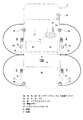
FIG. 1 is a block diagram showing a configuration of a smart keyless device for a vehicle according to an embodiment of the present invention, and FIG. 2 is a schematic diagram of a vehicle X equipped with an in-vehicle device. This smart keyless device includes an in-vehicle device constituted by the smart
スマートキーレス制御ユニット1には、例えばLF磁界を発生させるコイルにより構成された5つのスマートキーレスLF送信アンテナ3a〜3eが接続されており、これらは図2において一点鎖線で示す車両Xに設置されている。3aは運転席(以下「D席」という)4a近傍に設けられる車外D席用アンテナ、3bは助手席(以下「P席」という)4b近傍に設けられる車外P席用アンテナ、3cは後席4cのD席4a後部側近傍に設けられる車外後席用右アンテナ、3dは後席4cのP席4b後部側近傍に設けられる車外後席用左アンテナ、3eは車室R(図中の一点鎖線により囲まれた領域)内に設けられる車室内アンテナである。目的に応じてこれらの送信アンテナを切換えることにより、異なる送信エリア(即ち、携帯機2の検知エリア)が形成される。なお、本実施形態では、D席4a側を車両Xの右側、P席側を車両Xの左側と定義する。また、スマートキーレスLF送信アンテナ3a〜3eについて、図1においては、図示の便宜上、車外アンテナ3a〜3d、車室内アンテナ3eと称してこれらを区別して示すとともに、以降車外D席用アンテナ3a、車外P席用アンテナ3b…とも称することとする。
The smart
図2において太い実線で示す領域A、B、C、Dはそれぞれ、車外D席用アンテナ3a、車外P席用アンテナ3b、車外後席用右アンテナ3c、車外後席用左アンテナ3dの送信エリアであり、これら4つのアンテナによって車両Xの側部外側のエリアがカバーされる。また、車室内アンテナ3eによって、車室R内のエリアがカバーされる。
In FIG. 2, areas A, B, C, and D indicated by thick solid lines are the transmission areas of the
一方、図1に示す携帯機2には、携帯機識別コード送信機より送信される携帯機識別コードとして携帯機2毎に異なるコードが設定されており、携帯機2は、この携帯機識別コードの送信制御を行う携帯機制御ユニット21を有している。この携帯機制御ユニット21には、遠隔操作でドアロックするためのロックスイッチ22、遠隔操作でドアロックを解除するためのアンロックスイッチ23の他、送信アンテナ24、受信アンテナ25が接続されており、互いの信号の授受が可能となっている。
On the other hand, in the
送信アンテナ24は、携帯機2固有の上記携帯機識別コード、ドアロックのためのロック信号及びドアロックを解除するためのアンロック信号を無線送信するものであり、受信アンテナ25は、車載機(スマートキーレスLF送信アンテナ3a〜3e)からのLF信号(LF磁界)を受信するものである。
The transmitting
ここで、乗員が携帯機2を携帯した状態で、車室Rの外の領域A〜D内に居る時には、携帯機2が受信アンテナ25でLF信号を受信することにより、無線応答信号として上記携帯機識別コードを送信アンテナ24から送信するようになっている。この携帯機識別コードは、車室Rの外部に設置された、図1に示す車載受信アンテナ5により受信される。なお、携帯機2より送信される無線応答信号としては、例えば、LF信号よりも周波数領域の高いUHF信号等のRF信号(電波)が用いられる。
Here, when the occupant is in the areas A to D outside the passenger compartment R with the
スマートキーレス制御ユニット1は、車載受信アンテナ5を介して受信した携帯機識別コードが、予めスマートキーレス制御ユニット1の記憶装置1aに登録記憶された携帯機識別コード(即ち、車載機の識別コード)と一致するか否かにより、携帯機2が当該車両の正規のものであるか否かを判定し、携帯機2が正規のものである(受信した携帯機識別コードが登録された携帯機識別コードと一致する)との判定である正規判定時には、車両と乗員との距離、つまり乗員が携帯する携帯機2より送信された無線応答信号の電波の強さ、即ち受信電界強度に応じてドアロックアクチュエータ6を作動させ、図2に示す車両Xのドア7a〜7dのロック・アンロックを行う。
In the smart
即ち、車両Xと乗員との距離が所定値よりも小さい(上記受信電界強度が所定値よりも大きい)時には、ドア7a〜7dをアンロックする一方、車両と乗員との距離が所定値以上である(上記受信電界強度が所定値以下である)時には、ドア7a〜7dをロックする。なお、ドア7a〜7dは、それぞれD席4a用、P席4b用、後席4c右側用、後席4c左側用であり、これらドア7a〜7dに対応してスマートキーレスLF送信アンテナ3a〜3dが配置されている。
That is, when the distance between the vehicle X and the occupant is smaller than a predetermined value (the reception electric field strength is larger than the predetermined value), the
また、これらドア7a〜7dのロック・アンロックは、D席4a側またはP席4b側のそれぞれのドア7a、7bのドアノブ7a1、7b1(図3参照)等に設けられた車室Rの外側のドアアクセススイッチ8a、8bや、携帯機2のロックスイッチ22、アンロックスイッチ23等によって制御することも可能である。
The
例えば、ドアアクセススイッチ8a、8bについては、車室Rの外側から押下操作可能な押しボタン式とされ、これらが押下操作されるとスマートキーレス制御ユニット1がドアアクセススイッチ信号を受信するようにするようなっている。
For example, the
一方、図1に示すロックスイッチ22、アンロックスイッチ23については、これらも押しボタン式とされ、いずれかが押下操作されると、携帯機制御ユニット21の制御によって送信アンテナ24が携帯機識別コードとともにロック信号またはアンロック信号のいずれかを送信し、スマートキーレス制御ユニット1が車載受信アンテナ5を介してこれを受信するようになっている。
On the other hand, the
そして、スマートキーレス制御ユニット1は、上記ドアアクセススイッチ信号、またはロック信号、アンロック信号(以下、これらを総称して操作信号という)を受信すると、ドアロックアクチュエータ6を作動させ、ドア7a〜7dをロックまたはアンロックするようになっている。
When the smart
即ち、ドアアクセススイッチ8a、8b、ロックスイッチ22、アンロックスイッチ23は、操作者がドア7a〜7dをロック操作する時またはアンロック操作する時に、押下操作によってその意思表示が行えるようにするためのものであり、換言すれば、これらの押下操作によりロック操作またはアンロック操作の意思の有無を検出するものとなっている。
That is, the
また、車両Xには、図2に示すように各ドア7a〜7dに対応してこれらの開閉を検知するドアスイッチ9a〜9dが設けられており、スマートキーレス制御ユニット1は、これらの検知信号も受信可能となっている。なお、ドアアクセススイッチ8a、8b、ドアスイッチ9a〜9dについて、図1では図示の便宜上1つにまとめて示している。
Further, as shown in FIG. 2, the vehicle X is provided with
さらに、本実施形態では、エンジンの作動中携帯機が車外に持ち出されることで、次回にドアのロック・アンロック制御やエンジンの再始動を行おうとしても携帯機が手元にないためにできないという事態を確実に防止すべく、携帯機2の持ち出し者に警報を行う警報ブザー10が図1に示すブザー音制御回路11によって制御可能に設けられている。この警報ブザー10は、図2に示すように車室R前側のD席4a(右側)前方の位置に設けられ、例えば不図示のフェンダパネルの裏側(内側)に取付けられる。
Furthermore, in this embodiment, when the portable device is taken out of the vehicle while the engine is operating, the next time the door is locked / unlocked or the engine is restarted, the portable device is not at hand, which is impossible. In order to prevent the situation with certainty, an
スマートキーレス制御ユニット1は、ブザー音制御回路11に制御信号を送信可能であり、後述するACC電源ライン12、IG電源ライン13への通電状態に基づいて、携帯機2の持ち出しが発生した時に警報を行うための制御信号を送信すべき状態にあるか否かを判定するようになっている。
The smart
ACC電源ライン12、IG電源ライン13は、図2に示すイグニッションスタータ14の操作によって電源(不図示)から電力供給がなされ、通電が開始されるようになっている。イグニッションスタータ14は、エンジンを始動させるための操作手段であり、そのキーノブ14aが回転操作されることによって、アクセサリ(ACC)OFF、アクセサリON、イグニッション(IG)ON、イグニッションSTARTの4つの操作を切換えることができる。
The ACC
ACC電源ライン12、IGライン13は、イグニッションスタータ14のアクセサリON操作時、イグニッションON操作時にそれぞれ通電が開始され、イグニッションスタータ14がイグニッションSTARTへ操作されると、エンジン制御ユニット15(図1参照)の始動制御によってエンジンの始動が開始される。
The ACC
ここで、イグニッションスタータ14のキーノブ14aのロック解除制御について説明する。
Here, the lock release control of the
車両Xを駐車させた状態においては、イグニッションスタータ14はアクセサリOFFの位置に操作されており、イグニッションスタータ14のキーノブ14a及びステアリング16(図2参照)はロックされている。なお、図2中に示す部材17は、メータユニット(不図示)等の車載装置が取付けられるインストルメントパネルである。
In the state where the vehicle X is parked, the
先ず、車両に乗車した運転者は、キーノブ14aを押圧操作する。キーノブ14aを押圧操作すると、車室内アンテナ3eからLF信号が送信される。このLF信号に対して携帯機2から携帯機識別コードが返信され、携帯機識別コードの照合が行われる。
First, the driver who gets on the vehicle presses the
この携帯機識別コードが、上記車載機の識別コードと一致することによって、キーノブ14aのロックが解除され、イグニッションスタータ14を、アクセサリON、イグニッションON、イグニッションSTARTへ回転操作することができるようになる。以下、アクセサリON、イグニッションON、イグニッションSTARTのいずれかの状態(ACC電源ライン12、IGライン13のいずれかの通電状態)を、イグニッションスタータ14の作動状態という。なお、イグニッションスタータ14は、回転操作を伴うもの以外に、プッシュボタンにより構成され、押下操作を伴うものであってもよい。
When the portable device identification code matches the identification code of the in-vehicle device, the
ここで、イグニッションスタータ14が作動状態となった時、携帯機2の持ち出しが発生すれば、警報ブザー10は、スマートキーレス制御ユニット1、ブザー音制御回路11により制御される音量、時間等に基づいて吹鳴し、警報を行うようになっている。
Here, when the
しかしながら、イグニッションスタータ14が上記作動状態にあるにもかかわらず、車両に再び戻ることが可能な用事であるが故に携帯機を持ったまま意図的に車外へ出る場合もあり、この場合、警報ブザー10による警報は無駄なものとなるばかりではなく、持ち出し者等に対して煩わしさを与えるものとなってしまう。
However, even though the
ところで、上述のようにイグニッションスタータ14が作動状態となった時、車両Xのドアアクセススイッチ8a、8b及び携帯機2のロックスイッチ22、アンロックスイッチ23によるロック・アンロック操作は、例えば特開2006−207264号公報に開示されているように、スマートキーレス制御ユニット1によって無効とされる(上記操作によるロック・アンロック制御がなされない)ようになっている。これは、エンジン作動中を含むイグニッションスタータ14の作動状態で不用意にドア7a〜7dのロック・アンロック操作がなされることを防止するためである。
By the way, when the
従って、イグニッションスタータ14が作動状態とされた時には、ドアアクセススイッチ8a、8b及びロックスイッチ22、アンロックスイッチ23はドア7a〜7dのロック・アンロック操作のためのスイッチとして機能しない状態となる。
Accordingly, when the
そこで、本実施形態では、ロック・アンロック操作を無効とされたドアアクセススイッチ8a、8b及びロックスイッチ22、アンロックスイッチ23を利用して、イグニッションスタータ14が作動状態となった時、上記スイッチ8a、8b、22、23のうちいずれかを操作すると、スマートキーレス制御ユニット1は上記警報を制限するようになっている。
Therefore, in the present embodiment, when the
具体的には、スマートキーレス制御ユニット1は、イグニッションスタータ14の作動状態でドア7a〜7dのいずれかが開閉操作された時、車室内アンテナ3eからLF信号を送信させるようになっており、ここで、携帯機2からの無線応答信号が無かった時(携帯機識別コードが送信されなかった時)、携帯機2の持ち出しが発生したとみなすようになっている。
Specifically, the smart
そして、スマートキーレス制御ユニット1は、このタイミングで上記スイッチ8a、8b、22、23のいずれかが操作されたか否かを判定し、該操作がなされたと判定すると、ブザー音制御回路11に制御信号を送信して上記警報音を制限させるようになっている。
Then, the smart
これにより、新たな操作手段を設けなくても、既存のドアアクセススイッチ8a、8bまたはロックスイッチ22、アンロックスイッチ23の操作により必要に応じて上記警報を制限することができる。従って、操作部の増加は抑制され、操作者による操作ミスや、どの操作部を操作すればよいのか咄嗟に判断しにくくなるといった操作時の混乱等を防止できる。
As a result, the alarm can be limited as necessary by operating the existing
また、警報を制限するための操作手段として、ドア7a、7bに設けられたドアアクセススイッチ8a、8bを利用可能とすることで、携帯機2の持ち出し者がドア7a〜7dを開けて車外へ出た時に、上記持ち出し者の身近に位置する既存のスイッチを利用して容易に警報制限を行うことができる。
Further, by making it possible to use the
また、警報を制限するための操作手段として、携帯機2のロックスイッチ22、アンロックスイッチ23を利用可能とすることで、車両Xから離れてしまった状態であっても、持ち出し者が所持している携帯機2の既存のスイッチを利用して遠隔操作による警報制限を行うことができる。
In addition, the
以下、スマートキーレス制御ユニット1により実行される警報ブザー10の警報制限制御について、図4のフローチャートを参照しながら説明する。
Hereinafter, alarm limit control of the
先ず、スマートキーレス制御ユニット1は、イグニッションスタータ14の回転操作により、ACC電源ライン12かIG電源ライン13かが通電状態であるか否か(イグニッションスタータ14が作動状態であるか否か)を判定する(ステップs1)。ここで、いずれも通電されていない状態であると判定した場合には(ステップs1:NO)、処理をリターンする。
First, the smart
一方、スマートキーレス制御ユニット1は、ACC電源ライン12、IG電源ライン13のいずれかが通電状態であると判定した場合には(ステップs1:YES)、ステップs2に進み、各ドア7a〜7dのいずれかで開閉操作がなされたか否かを判定する。具体的には、各ドアスイッチ9a〜9dの検知信号に基づいて上記開閉操作の有無が判定される。
On the other hand, if the smart
ここで、スマートキーレス制御ユニット1は、ドアスイッチ9a〜9dによる上記検知信号に変化がなく、各ドア7a〜7dのいずれも開閉操作されていないと判定すると(ステップs2:NO)、処理をリターンし、ドアスイッチ9a〜9dのいずれかの検知信号に変化があり、ドア7a〜7dのいずれかで開閉操作されたと判定すると(ステップs2:YES)、ステップs3に進み、車室内アンテナ3eからLF信号を送信させる。
Here, when the smart
ここで、携帯機2から正規の携帯機識別コードを車載受信アンテナ5に送信する応答があった時(ステップs4:YES)、携帯機2が車室R内に存在しており、車外へは持ち出されていないと考えられるため、スマートキーレス制御ユニット1は処理をリターンする。
Here, when there is a response from the
一方、携帯機2から正規の携帯機識別コードを車載受信アンテナ5に送信する応答がなかった時(ステップs4:NO)、乗員が各ドア7a〜7dのいずれかを開閉操作して携帯機2を車外に持ち出したと考えられるため、スマートキーレス制御ユニット1は、先ずステップs5において、ドアアクセススイッチ8a、8bまたは携帯機2のロックスイッチ22、アンロックスイッチ23の操作がなされたか否かを判定する。具体的には、上記スイッチ8a、8b、22、23のいずれかの操作による操作信号をスマートキーレス制御ユニット1が受信したか否かで判定される。
On the other hand, when there is no response from the
ステップs5において、上記スイッチ8a、8b、22、23のいずれかの操作による上記操作信号を受信しなかった時(ステップs5:NO)、スマートキーレス制御ユニット1は、ブザー音制御回路11に対して制御信号を送信し、警報ブザー10の吹鳴による警報を行わせる(ステップs6)。
In step s5, when the operation signal due to the operation of any of the
この時、スマートキーレス制御ユニット1は吹鳴時間を計数しており、ステップs7においてこの吹鳴が開始されてから予め設定した所定時間経過したか否かを判定する。ここで、スマートキーレス制御ユニット1は、所定時間が経過したと判定した時(ステップs7:YES)、警報によるメッセージが届いていない位置まで持ち出し者が離れてしまったとみなして警報ブザー10の吹鳴を停止し(ステップs8)、処理をリターンする。
At this time, the smart
一方、ステップs5において、上記操作信号を受信した時(ステップs5:YES)、スマートキーレス制御ユニット1は、警報ブザー10による警報を禁止して(ステップs8)、処理をリターンする。
On the other hand, when the operation signal is received in step s5 (step s5: YES), the smart
このように、警報ブザー10による警報がなされる前に、上記操作信号を受信していた時、即ち、上記スイッチ8a、8b、22、23のいずれかが予め操作されていた時には、上記警報を禁止することで煩わしさを完全に解消することができる。
Thus, when the operation signal is received before the alarm by the
また、ステップs7において警報が開始されてから所定時間が経過していないと判定した時には(ステップs7:NO)、ステップs5の判定を繰り返して、警報中に上記操作信号を受信したか否かを判定するようになっている。 When it is determined in step s7 that the predetermined time has not elapsed since the alarm was started (step s7: NO), the determination in step s5 is repeated to determine whether the operation signal is received during the alarm. It comes to judge.
ここで、上記操作信号を受信していなければ、スマートキーレス制御ユニット1は、ステップs6、s7の判定を繰り返し、上記操作信号を受信すればステップs8に進んで上記警報を停止する。
Here, if the operation signal has not been received, the smart
従って、警報を制限するとは、警報がなされる前であれば警報を禁止することを意味し、警報中であれば、その警報を停止することを意味することになる。 Therefore, restricting the alarm means prohibiting the alarm before the alarm is issued, and stopping the alarm when the alarm is in progress.
このように、警報ブザー10は、ステップs2においていずれかのドア7a〜7dが開閉操作されたことが検出され、且つステップs4において携帯機2からの無線応答信号が無かった時に車室Rに向けて警報を行うようになっている。これにより、ドア7a〜7dのいずれかが開けられ、且つ携帯機2が車外に持ち出された時に警報を行うものや、携帯機2が車外に持ち出され、且つドア7a〜7dのいずれかが閉められた時に警報を行うものに対して警報制限を行うことができる。
Thus, the
また、この場合ドア7a〜7dの状態の変化に基づいて警報を行うべきか否かの判定を容易に行うことが可能となっており、換言すれば、必要に応じて警報の制限(禁止、停止)制御を行うべき状態となったか否かを容易に判定することができる。
Further, in this case, it is possible to easily determine whether or not an alarm should be performed based on a change in the state of the
なお、上述した実施形態では、単一の警報ブザー10で警報がなされる場合を説明したが、本発明は必ずしもこれに限定されるものではない。例えば、図5、図6に示すように車両X’の車室R内に設けた警報ブザー18a、インジケータ18bを含む複数の警報手段で警報を行うものに本発明を適用してもよい。以下の実施形態において、最初の実施形態と同様の構成要素については同一の符号を付して、その説明を省略する。
In addition, although embodiment mentioned above demonstrated the case where an alarm was made with the
図5、図6に示す実施形態においては、警報ブザー18a、インジケータ18bは、いずれも図5に示すインストルメントパネル17のD席4a側に設けられたメータユニット(不図示)に取付けられ、それぞれ図5に示すブザー音制御回路19a、インジケータ表示制御回路19bにより制御される。
In the embodiment shown in FIGS. 5 and 6, the
警報ブザー18aは、ブザー音制御回路19aにより制御される音量等に基づいて吹鳴するようになっているものであり、車外に出ようとしている状態の持ち出し者及び車室R内の乗員に対して警報を行うものとなっている。これに対し、警報ブザー10は、車外に出てしまった持ち出し者に対して警報を行うものとなっている。
The
従って、警報ブザー18aは、警報音が発せられる先端が車室R内に向けられるようにして配設されており、車室内ブザーとして機能するようになっている。これに対し、警報ブザー10は、警報音が発せられる先端が車外に向けられるようにして配設されており、車外ブザーとして機能するようになっている。
Therefore, the
そして、警報ブザー10は車外に出てしまった持ち出し者に対して警報を行うべく、警報ブザー18aよりもその警報音つまり警報の強調レベルが高く設定されており、段階的に警報の強調レベルが高められるようになっている。
The
また、インジケータ18bは、インジケータ表示制御回路19bにより点滅表示制御されるようになっているものであり、この点滅表示により、車外に出ようとしている状態の上記持ち出し者及び車室R内の乗員に対して警報を行うものとなっている。
The
さらに、警報ブザー18a、インジケータ18bは、車外に出ようとしている持ち出し者及び車室R内の乗員に対して警報を行うために、ドアスイッチ9a〜9dによりいずれかのドア7a〜7dが開操作されたことが検出され、且つ携帯機2からの無線応答信号が無かった時に車室Rに向けて警報を行うようになっている。
Further, the
また、警報ブザー10は、車外に出てしまった持ち出し者に対して警報を行うべく、ドアスイッチ9a〜9dのいずれかの検知信号に基づいていずれかのドア7a〜7dが閉操作されたことが検出され、且つ携帯機2からの無線応答信号がなかった時に車外に向けて警報を行うようになっている。
Further, the
そして、本実施形態では、上記スイッチ8a、8b、22、23のいずれかの操作による操作信号をスマートキーレス制御ユニット1が受信したとしても、車室内用の警報ブザー18a、インジケータ18bによる警報は行いつつ、車外用の警報ブザー10による警報のみを制限するようになっている。
And in this embodiment, even if the smart
このため、車室内用の警報ブザー18a、インジケータ18bによる警報を第1の警報として、これを車室R内に残る乗員向けの警報とすることができる。そして、警報ブザー10による警報を第2の警報としてこれを制限することにより、警報の強調レベルが高く、しかも車外に向けて警報が発せられるものを制限することになるため、警報の制限がより効果的なものとなり、且つ、車両X’の周囲へ与える煩わしさを抑制することができる。
For this reason, the warning by the
このように、複数の警報が行われるものにおいては、上述したように必要に応じて限定的に警報を制限することも可能であり、上記スイッチ8a、8b、22、23の操作によらず、不可欠と考えられる警報についてはこれを行えるようにすることができる。
Thus, in the case where a plurality of alarms are performed, it is also possible to limit the alarms limitedly as necessary as described above, regardless of the operation of the
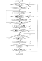
以下、スマートキーレス制御ユニット1により実行される警報ブザー10、ザー18a、インジケータ18bの警報制限制御の別の実施形態について、図7のフローチャートを参照しながら説明する。
Hereinafter, another embodiment of the alarm restriction control of the
図7に示すフローチャートにおけるステップs11は、図4に示すフローチャートにおけるステップs1に対応しており、スマートキーレス制御ユニット1は、ACC電源ライン12、IG電源ライン13のいずれかが通電状態であると判定した場合には(ステップs11:YES)、ステップs12に進み、ドアスイッチ9a〜9dの検知信号に基づいて各ドア7a〜7dのいずれかで開操作がなされたか否かを判定する。
Step s11 in the flowchart shown in FIG. 7 corresponds to step s1 in the flowchart shown in FIG. 4, and the smart
ここで、スマートキーレス制御ユニット1は、各ドア7a〜7dのいずれも開操作されていないと判定すると(ステップs12:NO)、処理をリターンし、ドア7a〜7dのいずれかで開操作されたと判定すると(ステップs12:YES)、ステップs13に進んで車室内アンテナ3eからLF信号を送信させる。
Here, if the smart
ここで、携帯機2から正規の携帯機識別コードを車載受信アンテナ5に送信する応答があった時(ステップs14:YES)、スマートキーレス制御ユニット1は、図4のステップs4と同様処理をリターンする一方、上記応答がなかった時には(ステップs14:NO)、乗員が各ドア7a〜7dのいずれかを開操作して携帯機2を車外に持ち出そうとしていると考えられるため、この時には警報ブザー18aを吹鳴させつつ、インジケータ18bを点滅表示させることで、持ち出し者及び車室R内の乗員に対して警報を行う(ステップs15)。この時、上記スイッチ8a、8b、22、23による操作がなされたか否かは判定されないようになっている。
Here, when there is a response from the
次に、スマートキーレス制御ユニット1はステップs16に進んで、ドアスイッチ9a〜9dの検知信号に基づいて持ち出し者により開操作されたドアが閉操作されたか否かを判定する。ここで、閉操作がなされていないと判定すると(ステップs16:NO)、スマートキーレス制御ユニット1はステップs13〜ステップs16の処理を繰り返し、閉操作がなされたと判定すると(ステップs16:YES)、ステップs17に進んで車室内アンテナ3eからLF信号を再度送信させる。
Next, the smart
そして、携帯機2から正規の携帯機識別コードを車載受信アンテナ5に送信する応答があった時(ステップs18:YES)、スマートキーレス制御ユニット1は、最終的に携帯機2の持ち出しは行われなかったとみなして処理をリターンする。
When there is a response from the
一方、携帯機2から正規の携帯機識別コードを車載受信アンテナ5に送信する応答がなかった時(ステップs18:NO)、乗員が上記ドアを閉操作して携帯機2を車外に持ち出したと考えられるため、ここで、ステップs19に進んで上記スイッチ8a、8b、22、23のいずれかが操作されたか否かを判定する。以降、スマートキーレス制御ユニット1は、ステップs19〜s22において、図4のステップs5〜ステップs8に対応した処理を実行することになり、上記操作信号の有無に基づいて、警報ブザー10の警報の禁止、停止の必要性を判定することになる。
On the other hand, when there is no response from the
ところで、上述した各実施形態においては、警報ブザー10、18aによる制限を、警報の停止または禁止により実現することとしたが、これに限定されることはなく、例えば、ブザー吹鳴時の強調レベルを低減させるようにしてもよい。例えば、ブザー音制御回路11、19により音量、周波数等を制御するようにしてもよい。
By the way, in each of the above-described embodiments, the limitation by the
また、警報の仕方についても、警報ブザー10、18a、インジケータ18bのように聴覚、視覚を刺激することには限定されない。例えば、携帯機2の持ち出し時に、スマートキーレス制御ユニット1からの無線信号により携帯機2を振動させるようにしてもよい。この場合、振動の振幅、周波数等を制御することにより強調レベルを制御することができる。
Also, the method of alarming is not limited to stimulating hearing and vision like the
また、このドアアクセススイッチ8a、8bは、押下操作することなく手を接触させるだけで反応する接触センサで構成してもよい。この場合、接触時に指紋の読取りを行うことが可能な接触センサにより構成することが可能であり、スマートキーレス制御ユニット1の記憶装置1a内に、予め正規の所有者の指紋を登録することで、接触時に読取られた指紋と一致するか否かの認証制御を行うことも可能になる。
Further, the
また、ドアアクセススイッチ8a、8bを、手を近づけるだけで反応する近接センサで構成してもよい。この場合操作者の体の一部(例えば手)が図3に示すドアノブ7a1、7b1に近付いたことを検出することで、その操作者による車外からのロック・アンロック操作を検出できる静電容量検出センサ、赤外線センサ等により構成することが可能である。
Further, the
また、上述した各実施形態では、警報を制限するための操作手段として、ドアアクセススイッチ8a、8bまたは携帯機2のロックスイッチ22、アンロックスイッチ23を採用しているが、必ずしもこれに限定されない。例えば、スライドドアやリヤゲートを備える車両において、イグニッションスタータ14が作動状態の時にこれらのロック・アンロック操作が無効とされるものであれば、上記スライドドアやリヤゲートを操作するためのスイッチを採用してもよい。
Further, in each of the above-described embodiments, the
また、エンジン始動を遠隔操作するためのエンジン始動スイッチを携帯機2に備えるものであれば、これを採用してもよい。
In addition, if the
また、図5、図6に示す実施形態において、警報ブザー10、18a、インジケータ18bによる警報を全て制限するように変更しても良いことは勿論である。
Moreover, in embodiment shown in FIG. 5, FIG. 6, it is needless to say that it may change so that all the alarms by the
この発明の構成と、上述の実施形態との対応において、
この発明のロック・アンロック制御手段は、スマートキーレス制御ユニット1に対応し、
以下同様に、
始動制御手段は、エンジン制御ユニット15に対応し、
エンジン始動手段は、イグニッションスタータ14に対応し、
警報手段は、警報ブザー10、18a、インジケータ18bに対応し、
スマートキーレス操作手段は、ドアアクセススイッチ8a、8b、ロックスイッチ22、アンロックスイッチ23に対応し、
警報制限手段は、ステップs8、s22を実行するスマートキーレス制御ユニット1に対応し、
ドアに設けられた検出手段は、ドアアクセススイッチ8a、8bに対応し、
携帯機に設けられた検出手段は、ロックスイッチ22、アンロックスイッチ23に対応するも、
この発明は、上述の実施形態の構成のみに限定されるものではなく、多くの実施の形態を得ることができる。
In correspondence between the configuration of the present invention and the above-described embodiment,
The lock / unlock control means of the present invention corresponds to the smart
Similarly,
The start control means corresponds to the
The engine starting means corresponds to the
The alarm means corresponds to the
The smart keyless operation means corresponds to the
The alarm limiting means corresponds to the smart
The detection means provided on the door corresponds to the
The detection means provided in the portable device corresponds to the
The present invention is not limited only to the configuration of the above-described embodiment, and many embodiments can be obtained.
1…スマートキーレス制御ユニット
2…携帯機
7a、7b、7c、7d…ドア
8a、8b…ドアアクセススイッチ
10、18a…警報ブザー
18b…インジケータ
14…イグニッションスタータ
15…エンジン制御ユニット
22…ロックスイッチ
23…アンロックスイッチ
R…車室
X、X’…車両
DESCRIPTION OF
Claims (10)
エンジン始動手段が作動状態で上記携帯機が車外に持ち出された時に警報を行う警報手段と、
上記エンジン始動手段が作動状態にある時に操作が無効とされるスマートキーレス操作手段と、
該スマートキーレス操作手段が操作された時に上記警報手段の警報を制限する警報制限手段とを備えた
車両のスマートキーレス装置。 Lock / unlock control means for locking / unlocking the vehicle door when the identification code of the in-vehicle device mounted on the vehicle matches the identification code of the portable device carried by the passenger, and engine start control A smart keyless device for a vehicle having a start control means,
Alarm means for giving an alarm when the portable device is taken out of the vehicle when the engine starting means is in operation; and
Smart keyless operation means whose operation is invalidated when the engine starting means is in an operating state;
A smart keyless device for a vehicle, comprising: an alarm limiting unit that limits an alarm of the alarm unit when the smart keyless operation unit is operated.
請求項1記載の車両のスマートキーレス装置。 The smart keyless device for a vehicle according to claim 1, wherein the alarm restriction unit prohibits the alarm when the smart keyless operation unit is operated before performing the alarm.
請求項1または2記載の車両のスマートキーレス装置。 3. The smart keyless device for a vehicle according to claim 1, wherein the alarm means issues an alarm when the portable device is taken out of the vehicle and the door is closed.
請求項1または2記載の車両のスマートキーレス装置。 3. The smart keyless device for a vehicle according to claim 1, wherein the alarm means issues an alarm when the door is opened and the portable device is taken out of the vehicle.
上記携帯機が車外に持ち出され、且つ上記ドアが閉められた時に第2の警報を行うものである
請求項1または2記載の車両のスマートキーレス装置。 The alarm means performs a first alarm when the door is opened and the portable device is taken out of the vehicle,
The smart keyless device for a vehicle according to claim 1 or 2, wherein a second alarm is given when the portable device is taken out of the vehicle and the door is closed.
請求項5記載の車両のスマートキーレス装置。 6. The smart keyless device for a vehicle according to claim 5, wherein the alarm limiting means is configured to limit the second alarm.
請求項6記載の車両のスマートキーレス装置。 The smart keyless device for a vehicle according to claim 6, wherein an emphasis level of the second alarm is set higher than an emphasis level of the first alarm.
請求項6または7記載の車両のスマートキーレス装置。 8. The smart keyless device for a vehicle according to claim 6 or 7, wherein the alarm means performs the first alarm toward the vehicle interior and also performs the second alarm toward the outside of the vehicle.
請求項1〜8のいずれか一項に記載の車両のスマートキーレス装置。 The smart keyless device for a vehicle according to any one of claims 1 to 8, wherein the smart keyless operation means is detection means provided on the door to detect whether or not the user intends to operate.
請求項1〜9のいずれか一項に記載の車両のスマートキーレス装置。 The smart keyless device for a vehicle according to any one of claims 1 to 9, wherein the smart keyless operation means is detection means provided in the portable device to detect whether or not there is an intention to operate.
Priority Applications (1)
| Application Number | Priority Date | Filing Date | Title |
|---|---|---|---|
| JP2007043380A JP4867706B2 (en) | 2007-02-23 | 2007-02-23 | Smart keyless device for vehicle |
Applications Claiming Priority (1)
| Application Number | Priority Date | Filing Date | Title |
|---|---|---|---|
| JP2007043380A JP4867706B2 (en) | 2007-02-23 | 2007-02-23 | Smart keyless device for vehicle |
Publications (2)
| Publication Number | Publication Date |
|---|---|
| JP2008208525A JP2008208525A (en) | 2008-09-11 |
| JP4867706B2 true JP4867706B2 (en) | 2012-02-01 |
Family
ID=39785064
Family Applications (1)
| Application Number | Title | Priority Date | Filing Date |
|---|---|---|---|
| JP2007043380A Expired - Fee Related JP4867706B2 (en) | 2007-02-23 | 2007-02-23 | Smart keyless device for vehicle |
Country Status (1)
| Country | Link |
|---|---|
| JP (1) | JP4867706B2 (en) |
Families Citing this family (8)
| Publication number | Priority date | Publication date | Assignee | Title |
|---|---|---|---|---|
| JP5024258B2 (en) * | 2008-09-26 | 2012-09-12 | 三菱自動車工業株式会社 | Driver support device |
| JP5508240B2 (en) * | 2010-12-01 | 2014-05-28 | 株式会社東海理化電機製作所 | Electronic key system |
| CN103354786B (en) | 2010-12-24 | 2016-05-25 | 丰田自动车株式会社 | Vehicle electronic key system |
| JP2013256164A (en) * | 2012-06-11 | 2013-12-26 | Omron Automotive Electronics Co Ltd | Vehicle control device, vehicle system and control method |
| KR101976595B1 (en) * | 2013-04-10 | 2019-05-09 | 콘티넨탈 오토모티브 시스템 주식회사 | Automatic alarm system of automobile using smart key and control method thereof |
| JP2017013713A (en) * | 2015-07-03 | 2017-01-19 | 富士重工業株式会社 | Alighting detection device of electronic key system for vehicle |
| JP6626282B2 (en) * | 2015-07-14 | 2019-12-25 | 株式会社Subaru | Alighting detection device of electronic key system for vehicles |
| JP2019156056A (en) * | 2018-03-09 | 2019-09-19 | 株式会社オートネットワーク技術研究所 | On-vehicle radio communication device, communication system, portable communication device, communication program, and communication method |
Family Cites Families (2)
| Publication number | Priority date | Publication date | Assignee | Title |
|---|---|---|---|---|
| JP4279506B2 (en) * | 2002-04-24 | 2009-06-17 | 株式会社東海理化電機製作所 | Remote control device for vehicle and drive warning method |
| JP4587064B2 (en) * | 2004-09-30 | 2010-11-24 | マツダ株式会社 | Smart keyless control device |
-
2007
- 2007-02-23 JP JP2007043380A patent/JP4867706B2/en not_active Expired - Fee Related
Also Published As
| Publication number | Publication date |
|---|---|
| JP2008208525A (en) | 2008-09-11 |
Similar Documents
| Publication | Publication Date | Title |
|---|---|---|
| JP4867706B2 (en) | Smart keyless device for vehicle | |
| US20090096578A1 (en) | Smart entry system | |
| JP4047715B2 (en) | Security system and portable device for security system | |
| JP4476062B2 (en) | In-vehicle control device | |
| US7425886B2 (en) | Smart entry system for vehicle | |
| EP3309755B1 (en) | Biometric-electronic key system | |
| JP4140731B2 (en) | Vehicle communication device | |
| US20070229219A1 (en) | In-vehicle device remote control system | |
| JP4485296B2 (en) | Smart key system | |
| JP2000118354A (en) | Vehicle safety system having key-less going action capability | |
| JP4349040B2 (en) | Vehicle door unlock control device | |
| JP4213719B2 (en) | In-vehicle device remote control device | |
| JP4254547B2 (en) | Vehicle anti-theft system | |
| EP2199503B1 (en) | Vehicle door locking system, keyless entry system, and locking control method | |
| JP2008106579A (en) | Smart keyless device for vehicle | |
| JP3659583B2 (en) | In-vehicle device remote control system | |
| JP4274156B2 (en) | Smart entry system for vehicles | |
| JP4600296B2 (en) | Electronic key system for vehicles | |
| JP2005232989A (en) | Engine starting control device | |
| EP3470275B1 (en) | Wireless communication system | |
| JP2009209578A (en) | Smart entry system | |
| TW201917705A (en) | Wireless communication system | |
| JP3582384B2 (en) | In-vehicle equipment remote control device | |
| JP5200799B2 (en) | Smart key system | |
| JP4367195B2 (en) | Wireless automatic encryption verification / unlocking device for vehicles |
Legal Events
| Date | Code | Title | Description |
|---|---|---|---|
| A621 | Written request for application examination |
Free format text: JAPANESE INTERMEDIATE CODE: A621 Effective date: 20100115 |
|
| A977 | Report on retrieval |
Free format text: JAPANESE INTERMEDIATE CODE: A971007 Effective date: 20111006 |
|
| TRDD | Decision of grant or rejection written | ||
| A01 | Written decision to grant a patent or to grant a registration (utility model) |
Free format text: JAPANESE INTERMEDIATE CODE: A01 Effective date: 20111018 |
|
| A01 | Written decision to grant a patent or to grant a registration (utility model) |
Free format text: JAPANESE INTERMEDIATE CODE: A01 |
|
| A61 | First payment of annual fees (during grant procedure) |
Free format text: JAPANESE INTERMEDIATE CODE: A61 Effective date: 20111031 |
|
| R150 | Certificate of patent or registration of utility model |
Ref document number: 4867706 Country of ref document: JP Free format text: JAPANESE INTERMEDIATE CODE: R150 Free format text: JAPANESE INTERMEDIATE CODE: R150 |
|
| FPAY | Renewal fee payment (event date is renewal date of database) |
Free format text: PAYMENT UNTIL: 20141125 Year of fee payment: 3 |
|
| LAPS | Cancellation because of no payment of annual fees |