JP4862938B2 - Container with pallet rack, pallet rack unit and pallet rack - Google Patents
Container with pallet rack, pallet rack unit and pallet rack Download PDFInfo
- Publication number
- JP4862938B2 JP4862938B2 JP2009280590A JP2009280590A JP4862938B2 JP 4862938 B2 JP4862938 B2 JP 4862938B2 JP 2009280590 A JP2009280590 A JP 2009280590A JP 2009280590 A JP2009280590 A JP 2009280590A JP 4862938 B2 JP4862938 B2 JP 4862938B2
- Authority
- JP
- Japan
- Prior art keywords
- pallet
- pallet rack
- sub
- push
- container
- Prior art date
- Legal status (The legal status is an assumption and is not a legal conclusion. Google has not performed a legal analysis and makes no representation as to the accuracy of the status listed.)
- Expired - Fee Related
Links
Images


Description
本発明は、種々の物品を載置して運搬および保管する際などに使用されるパレットラック、パレットラックユニット及びパレットラックを備えたコンテナに関する。 The present invention relates to a pallet rack, a pallet rack unit, and a container provided with a pallet rack that are used when various articles are placed, transported, and stored.
従来、物品を運搬および保管する際、パレットの上に物品を積載した状態でパレットごと積載物品をコンテナに収容し、コンテナごと車両や貨物車、船舶、航空機等で運送されている(特許文献1参照)。
例えば、積載する物品が牛乳パックのカートン等、積層しても破損しにくいものである場合には、物品をパレットに直積みする。そして、物品の上にパレットを設置し、更にその上に物品を直積みして積層する。
しかし、物品がソーラーパネルや半導体パネル、液晶パネルなどのガラス板等を使用した精密製品(以下、単にパネルと略称する)である場合には、物品を直接段積みすると下段の物品が損傷するおそれがあるため、パネル等を段ボール箱に収納して積載し、その製品の上に他の製品を積載しないようにしている。また、パネル等を蓋のない容器内に収容し、その製品に直接上積みしないようにして製品を保護している。また、製品をパレットに積載してストレッチフィルムで製品とパレットの側面を巻き付けて固定することで、密封封止状態に包装して製品のズレを防止することも行われている。
Conventionally, when goods are transported and stored, the goods loaded on the pallet are stored in a container while the goods are loaded on the pallet, and the containers are transported by vehicle, freight car, ship, aircraft, etc. (Patent Document 1). reference).
For example, when an article to be loaded is a thing that is not easily damaged even when stacked, such as a carton of a milk pack, the article is directly stacked on a pallet. Then, a pallet is installed on the article, and further, the article is directly stacked thereon and stacked.
However, if the article is a precision product using a glass plate such as a solar panel, a semiconductor panel, or a liquid crystal panel (hereinafter simply referred to as a panel), the lower article may be damaged if the article is directly stacked. For this reason, panels and the like are stored and loaded in a cardboard box, and other products are not loaded on the product. In addition, panels and the like are housed in a container without a lid, and the product is protected so as not to be directly stacked on the product. In addition, the product is loaded in a hermetically sealed state by loading the product on a pallet and winding and fixing the side of the product and the pallet with a stretch film to prevent the product from shifting.
上述した積載方法では、パレットや容器内への物品の積載に手間がかかる欠点があった。そのため、棚形状のパレットラックをコンテナ内に設置して、各パレットラックの棚毎に製品を積載して輸送等することが行われている。この場合にはパレットラックの棚上の製品の上に空間があるために損傷するおそれがない。 The above-described loading method has a drawback that it takes time to load articles on pallets and containers. Therefore, a shelf-shaped pallet rack is installed in a container, and a product is loaded on each shelf of each pallet rack and transported. In this case, there is no risk of damage due to the space above the product on the shelf of the pallet rack.
しかしながら、このようなパレットラックを用いて物品を輸送した場合、物品をおろした後の復路の便では別の物品を搭載していない空の便であることが多く、輸送コストが増大してしまう。これに対し、輸送コストを低減させるために、往路の便で搬送した物品とは異なる別の物品を復路の便に積載すると物品の形状や寸法が異なる場合が多く、パレットラックの各棚の空間に積載できなかったり積載し難かったりすることがあった。この場合、大きなスペースを占有するパレットラックは邪魔であり、復路の物品積載スペースが小さくなるという欠点がある。 However, when an article is transported using such a pallet rack, the return flight after unloading the article is often an empty flight on which another article is not mounted, which increases the transportation cost. . On the other hand, in order to reduce the transportation cost, when an article different from the article conveyed on the outbound flight is loaded on the outbound flight, the shape and size of the article are often different, and the space of each shelf of the pallet rack In some cases, it could not be loaded or it was difficult to load. In this case, a pallet rack that occupies a large space is a hindrance, and there is a drawback that the article loading space on the return path becomes small.
本発明は、このような実情に鑑みて、寸法や形状の異なる物品を輸送する場合でも、従来よりも積載スペースを広く確保できるようにしたパレットラック、パレットラックユニット及びコンテナを提供することを目的とする。 SUMMARY OF THE INVENTION In view of such circumstances, the present invention provides a pallet rack, a pallet rack unit, and a container that can secure a wider loading space than before even when transporting articles having different dimensions and shapes. And
本発明によるパレットラックは、支柱に梁部材が連結されたものが対向して配設してなり、対向する梁部材間に複数のサブビームを架け渡してなる積載台を備えた折り畳み可能なパレットラックであって、サブビームは長さ方向途中部分で分離された2本のビーム部材を備え、該2本のビーム部材の内側端部同士が軸部によって回動可能に連結されて折り曲げ可能に配設され、2本のビームの外側端部がそれぞれ梁部材に取り付けられた支軸回りに回動可能に支持され、梁部材にはサブビームの付け根部分を押し上げる方向に付勢する押し上げ部材が設けられ、該押し上げ部材は、サブビームを押し上げ方向に押圧すると共に押し上げ方向の進退範囲が規制されたコマと、サブビームを押し上げ方向にコマを付勢する弾性部材とを備えていることを特徴とする。
本発明によるパレットラックによれば、物品やパレットをサブビームを架け渡した積載台から外すことで、サブビームは押し上げ部材によって押し上げられて折り曲げられ、更に手動等で押し上げ部材から離れるよう折り曲げることで折り畳まれた状態になり、物品または/及びパレットをサブビームの積載台に載置すると、その重みによってサブビームは押し上げ部材の付勢力に抗して直線状に保持される。そのため、パレットラックは折り畳み時には占有スペースが小さくなり、空いたスペースに他の物品を載置可能になる。しかも、サブビームの回転軸に近い付け根部分に押し上げ部材を設けたから、短い押し上げストロークでサブビームを大きく押し上げることができる。
A pallet rack according to the present invention is a foldable pallet rack provided with a loading table in which a plurality of sub beams are bridged between opposed beam members, each of which has a beam member connected to a support column. The sub- beam includes two beam members separated in the middle in the length direction , and the inner ends of the two beam members are rotatably connected by a shaft portion so as to be bent. is, the outer end of the two beams is rotatably supported around the support shaft attached to the beam member, respectively, the beam member is provided push-up member for urging in a direction to push up the base portion component of the sub-beams The push-up member includes a top that presses the sub-beam in the push-up direction and whose advance / retreat range is restricted in the push-up direction, and an elastic member that urges the sub-beam in the push-up direction . It is characterized by that.
According to the pallet rack of the present invention, the article and the pallet are removed from the loading platform on which the sub beam is bridged, so that the sub beam is pushed up and bent by the push-up member, and further folded by being bent away from the push-up member manually. When the article or / and the pallet are placed on the sub beam loading table, the sub beam is held in a straight line against the urging force of the push-up member by the weight. For this reason, the pallet rack occupies a small space when folded, and other articles can be placed in the empty space. In addition, since the push-up member is provided at the base portion near the rotation axis of the sub beam, the sub beam can be pushed up greatly with a short push-up stroke.
本発明に係わるパレットラックによれば、物品やパレット等の積載台となるサブビームが押し上げ方向に付勢されているから、パレットまたは/及び物品を積載した状態ではサブビームは押し上げ部材の付勢力に抗して水平状態に保持され、パレットや物品を取り外すとサブビームが押し上げられて折り曲げ状態となる。そのため、パレットラックの不使用状態ではパレットラックを折り畳んで他の物品の収容スペースを広く確保できる。 According to the pallet rack according to the present invention, the sub-beam, which is a loading table for articles and pallets, is urged in the pushing-up direction. When the pallet or the article is removed, the sub beam is pushed up to be bent. Therefore, when the pallet rack is not in use, the pallet rack can be folded to secure a large space for storing other articles.
本発明の実施の形態によるパレットラックでは、サブビームは押し上げ部材に押された第一段階の押し上げによる折り曲げと、更に押し上げ部材から離間した第二段階の押し上げによる折り曲げとが行われるようにしたことを特徴とする。
本実施形態によれば、パレットラックの積載台であるサブビームからパレットや物品が取り外された場合、押し上げ部材のコマがばね部材等の弾性部材の付勢力によって外側に突出してサブビームを押して第一段階の押し上げを行い、更にサブビームを手動等で折り曲げることでコマから離間させて第二段階の押し上げが行われてパレットラックが折り畳み状態になる。そのため、パレットラックはパレットや物品を積載しない状態で折り曲げ状態に保持され、その折り畳みを押し上げ部材の付勢力に基づいて容易に行うことができる。
The pallets according to the embodiment of the present invention, and so the bending by the first stage push-up of the service Bubimu pushed by the push-up member, O bent by pushing up the second stage remote from the further lifting member is carried out It is characterized by that.
According to the present embodiment, when a pallet or an article is removed from the sub beam which is a loading platform of the pallet rack, the top of the push-up member protrudes outward by the urging force of the elastic member such as the spring member and pushes the sub beam to the first stage. The pallet rack is in a folded state by further pushing up the sub-beam and then bending the sub-beam manually to separate it from the frame and pushing it up in the second stage. Therefore, the pallet rack is held in a folded state without loading pallets or articles, and the folding can be easily performed based on the urging force of the push-up member.
また、対向する一の梁部材に連結された支柱と他の梁部材に連結された支柱とを連結するスタビライザーが設けられ、スタビライザーは対向する一対の支柱を接近させることで折り畳み可能または折り曲げ可能とされていることが好ましい。
これにより、パレットラックはサブビームを折り曲げると、梁部材を介して連結された支柱が接近することに連動して、支柱の接近に追従してスタビライザーが折り畳まれまたは折り曲げられるから、折り畳みまたは折り曲げ時に支柱が捩れたりすることがなくスムーズに折り畳むことができる。
In addition, a stabilizer is provided to connect the strut connected to the opposite beam member and the strut connected to the other beam member, and the stabilizer can be folded or folded by bringing a pair of opposing struts close to each other. It is preferable that
As a result, when the pallet rack bends the sub beam, the stabilizer is folded or folded following the approach of the struts in conjunction with the approach of the struts connected via the beam members. Can be folded smoothly without twisting.
また、支柱の下端部には車輪が取り付けられており、支柱は弾性部材によって車輪に対してその長手方向に進退可能とされており、サブビームに物品または/及びパレットを積載すると弾性部材が圧縮されて支柱の下端部が車輪に対して相対的に降下して係止させるようにしてもよい。
パレットラックのサブビームに物品やパレットを積載しない状態では、支柱を含むパレットラックは弾性部材の付勢力によって車輪から離間する上昇位置に保持され、パレットラックは車輪で移動可能である。一方、サブビームに物品または/及びパレットを積載すると、物品または/及びパレットの重量によって支柱を含むパレットラックが弾性部材の付勢力に抗して車輪に重なる方向に降下させられて各支柱の下端部が床面または基板等に当接する降下位置で係止させられ、車輪による移動を阻止する。
In addition, a wheel is attached to the lower end of the column, and the column can be advanced and retracted in the longitudinal direction with respect to the wheel by an elastic member. When an article or / and pallet is loaded on the sub beam, the elastic member is compressed. Then, the lower end portion of the column may be lowered relative to the wheel and locked.
In a state where no article or pallet is loaded on the sub beam of the pallet rack, the pallet rack including the support column is held at the raised position separated from the wheel by the urging force of the elastic member, and the pallet rack can be moved by the wheel. On the other hand, when an article or / and a pallet is loaded on the sub beam, the pallet rack including the support is lowered in a direction overlapping the wheel against the urging force of the elastic member due to the weight of the article or / and the pallet. Is locked at a lowered position where it comes into contact with the floor surface or the substrate or the like, and prevents movement by the wheels.
また、本発明によるパレットラックユニットは、複数の上述したパレットラックが一体に形成され、互いに近接または当接する支柱は一体に形成されていることを特徴とする。
本発明によるパレットラックユニットによれば、複数のパレットラックを一体に形成することで、多くの物品をサブビームに載置できて、支柱の本数を少なくできるから部品点数を削減できて製造コストが低廉になる。
Further, the pallet rack unit according to the present invention is characterized in that a plurality of the above-described pallet racks are integrally formed, and struts that are close to or in contact with each other are integrally formed.
According to the pallet rack unit of the present invention, by forming a plurality of pallet racks integrally, many articles can be placed on the sub-beam, and the number of support columns can be reduced, so that the number of parts can be reduced and the manufacturing cost is low. become.
また、本発明によるコンテナは、基板と開口を除く周囲に形成された側壁とが設けられ、基板には上述した折り畳み可能なパレットラックが1または複数配設されていることを特徴とする。
本発明によれば、コンテナ内に複数のパレットラックを収納・保持して輸送できると共に、例えば往路で物品を各パレットラックに積載して輸送した後、復路で寸法や形状の異なる別の物品を積載して輸送する場合、コンテナに収容した複数のパレットラックを折り畳み状態にすることで空きスペースを大きく設定して別の物品の載置スペースを確保できるから、往復の輸送に際してスペースの無駄を抑制した輸送を行える。
The container according to the present invention is characterized in that a substrate and side walls formed around the opening are provided, and the substrate is provided with one or more foldable pallet racks.
According to the present invention, a plurality of pallet racks can be stored and held in a container and transported. For example, after an article is loaded and transported on each pallet rack in the forward path, another article having a different size or shape is returned on the return path. When loading and transporting, multiple pallet racks housed in containers can be folded to set a large free space to secure a space for loading other articles, reducing space waste during round-trip transportation Can be transported.
また、基板には、支柱の下端部に設けた車輪の走行をガイドするガイド溝が形成されていてもよく、コンテナへのパレットラックの出し入れをガイド溝に沿って容易に行える。
また、基板は着脱可能としてもよく、その場合、ガイド溝のない基板と差し替えることができて、既存のコンテナへも本発明によるパレットラックを収納して輸送できる。
Further, the substrate may be formed with a guide groove for guiding the traveling of the wheel provided at the lower end portion of the support column, and the pallet rack can be easily taken in and out of the container along the guide groove.
The substrate may be detachable, in which case it can be replaced with a substrate without a guide groove, and the pallet rack according to the present invention can be stored and transported to an existing container.
以下、本発明の実施例によるパレットラックとコンテナを図1乃至図11により説明する。
図1において、本発明の実施例によるコンテナ1は全体として例えば略直方体枠状に形成されており、基板2と、基板2の周囲の三方に設けた側壁3とを有している。コンテナ1の残りの側面には側壁3は設けられておらず開口4と扉を設けている。コンテナ1の基板2には、複数のガイド溝5が所定間隔で開口4から内奧部に向かって平行に形成されている。
コンテナ1は陸上輸送や海上輸送や航空機輸送等に用いられて各種の物品を搬送するものであり、本実施例では例えば船舶に積載されて海上輸送に用いられる。
コンテナ1内には積み荷用の物品を載置するための単体のパレットラック7が複数設けられており、各パレットラック7は一対のガイド溝5に沿ってコンテナ1内に取り出し可能に収容されている。図1に示す各パレットラック7には物品Pを載置するためのパレット8が搭載されている。
A pallet rack and a container according to an embodiment of the present invention will be described below with reference to FIGS.
In FIG. 1, a container 1 according to an embodiment of the present invention is formed, for example, in a substantially rectangular parallelepiped frame shape as a whole, and includes a
The container 1 is used for land transportation, sea transportation, aircraft transportation, and the like, and carries various articles. In this embodiment, the container 1 is loaded on a ship and used for sea transportation.
A plurality of single pallet racks 7 for placing articles for loading are provided in the container 1, and each
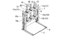
図2に示すパレットラック7は、物品用の積載台が例えば三段に形成されており、各段にパレット8が搭載されている。図2及び図3に示すパレットラック7は基板2上に支持されている。略直方体の枠状をなすパレットラック7に設けた四本の支柱10は対向する二つの側面を構成する一対の前側支柱10a,10aと背側支柱10b、10bである。前側支柱10a,10aと背側支柱10b、10bにはそれぞれ上下二段の梁部材11が固定されている。ここで、例えば上段の梁部材11を符号11a,下段の梁部材11を符号11bで示すとして、上段の梁部材11a、11aと下段の梁部材11b、11bは互いに対向して固定されている。
そして、上段の梁部材11a、11aには複数本(図では3本)の中折れ可能なサブビーム12が直交する方向に延びて架け渡されている。同様に下段の梁部材11b、11bにも複数本の中折れ可能なサブビーム12が直交する方向に架け渡されている。これら上下段の複数のサブビーム12、12は物品P等の積載台を構成する。
また、パレットラック7の対向する他の二つの側面において、前側支柱10aと背側支柱10bには例えば略H字形状のスタビライザー14が各端部14aで回動可能に支持されている。
The
A plurality (three in the figure) of
Further, on the other two side surfaces of the
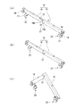
次にサブビーム12について図4乃至図6により説明する。
図4において、サブビーム12は例えば等しい長さの2本のビーム部材15、16で構成されている。これらビーム部材15,16は外側端部15a,16a両側に固定した断面略L字形状をなす一対の固定板18、18によって梁部材11,11に支持され、固定板18,18に取り付けられた支軸19回りに回動可能とされている。支軸19をサブビーム12の中央に設けたことで、折り畳み時にサブビーム12が略均等に分割されるので、折り畳み時の形状をバランスさせてその体積を小さくできる。
図4(a)において、ビーム部材15、16の内側端部15b、16b同士は軸部21によって回動可能に連結されている。そして、一方のビーム部材15は内側端部15bが切欠段部22を有すると共に軸部21を中心に円弧状に形成されている。他方のビーム部材16は内側端部16bがビーム部材15の内側端部15bを切欠段部22に係止するまで嵌合して嵌め合わされるよう断面コ字状に形成され、軸部21回りに回動可能とされている。
そして、図4(b)に示すようにビーム部材15,16の内側端部15b、16b同士を嵌合させると、両者間に段差が形成されない。しかも、サブビーム12の押し上げによる折り曲げ時にビーム部材15,16の内側端部15b、16bでの軸部21回りの折り曲げ回動がスムーズに行われる(図4(c)参照)。
なお、図3に示す実施例では、複数のサブビーム12におけるビーム部材15,16の嵌合構造について、一方のビーム部材15に切欠段部22を設けて他方のビーム部材16を嵌合させた構成を採用しているが、これと逆の構造、即ちビーム部材16に切欠段部22を設けた構成にしてもよい。そして、複数のサブビーム12における切欠段部22を設けるビーム部材をその配列方向に沿ってビーム部材15とビーム部材16の交互に形成させてもよい。この場合には、複数のサブビーム12による積載台の物品等の支持強度が一層安定する。
Next, the
In FIG. 4, the
In FIG. 4A, the
When the
In the embodiment shown in FIG. 3, with respect to the fitting structure of the
次にビーム部材15,16の押し上げ部材23について図5、図6により説明する。図5(a)において、ビーム部材15,16の外側端部15a,16aの下側に設けた支持部17、17は梁部材11、11にボルト等によって固定されている。各支持部17には係止板17aとガイド筒17bとが設けられ、上下端にフランジ部を有するコマ24が係止板17aの孔を貫通して上下方向に所定範囲で往復動可能に設けられている。ガイド筒17b内にはビーム部材15,16を押動して押し上げる方向にコマ24を付勢するばね部材25が装着されている。
そして、サブビーム12の上にパレット8または/及び物品Pが積載されている場合には、サブビーム12のビーム部材15,16がコマ24を押し、ばね部材25をその付勢力に抗して圧縮させてビーム部材15,16をガイド筒17b、17b上に当接させて、直線状に保持する(図5(a)参照)。なお、サブビーム12に少なくともパレット8または物品を載置させることで、サブビーム12は直線状に広がった状態に保持されるものとする。
サブビーム12からパレット8や物品が取り除かれた場合には、ばね部材25の付勢力でコマ24がガイド筒17bから突出しビーム部材15,16を押して押し上げ、支軸19回りに回動させる(図5(b)参照)。これにより、ビーム部材15,16がへの字型に折り曲げられ、サブビーム12が水平な状態で折り畳み方向に突っ張ることがなくなり、確実に折り畳むことができる。
更に、パレットラック7を折り畳んで前側支柱10a,10aと背側支柱10b、10bを接近させると、ビーム部材15,16はコマ24から離れて折り畳まれる(図5(c)、6参照)。
サブビーム12の回転軸に近い付け根部分に押し上げ部材23を設けたから、ばね部材25によるコマ24の小さいストロークでサブビーム12を大きく押し上げることができる。これに対し、押し上げ部材23が付け根部分から離れているとコマ24のストロークが長く且つばね部材25によるばね力をより強力にしなければならない。
Next, the push-up
When the
When the
Further, when the
Since the push-up
次に、スタビライザー14について図7により説明する。
図7(a)において、支柱10a、10b間に取り付けたスタビライザー14は、それぞれ支柱10a、10bに回動可能に上下に連結された各一対のアーム27、27と、上下の各2本のアーム27,27の自由端同士を支軸28、28で回転可能に連結する連結杆29とによって略H字状に形成されている。なお、支軸28、28はサブビーム12の軸部21と同一の垂直面上に位置するものとする。
スタビライザー14は自重によって各アーム27,27が下方に回動する方向に常時力を受けている。そのため、パレットラック7が折り畳まれ始めるとスタビライザー14は連動して自重で支軸28,28によって下方に折れ曲がる。パレットラック7が折り畳まれる際、各支柱10a、10bはスタビライザー14で連結されているから、捩れることなく平行移動する。
Next, the
In FIG. 7A, the
The
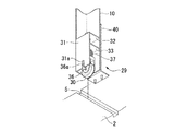
次に、パレットラック7の各支柱10の下端に設けた脚部29について図8及び図9により説明する。
パレットラック7の各支柱10は例えば断面略L字状に形成され、その下端の脚部29には車輪30とその収容部31が設けられている。収容部31は例えば断面略コ字状に形成されている。収容部31には上下方向に離間して第一係止板32及び第二係止板33が設けられ、これら第一及び第二係止板32,33を貫通して支持軸34が相対的に上下動可能に設けられている。支持軸34の上端にはストッパ35が設けられ、下端には支持枠36を介して車輪30が回転可能に支持されている。支持枠36と第二係止板33との間には弾性部材としてばね部材37が装着されている。
一方、図9において、コンテナ1の基板2には上述したように、各支柱10の車輪30が走行するガイド溝5が形成されており、ガイド溝5の外側にはガイド溝5より若干浅い係止溝39が形成されている。また、各ガイド溝5の外側には支柱10の位置を規制するガイド壁40が基板2に固定されている。
Next, the
Each
On the other hand, in FIG. 9, as described above, the
そして、図9において、パレットラック7の各支柱10の下端に設けた車輪30が基板2のガイド溝5に着地した状態で、図9(a)に示すようにパレットラック7にパレット8や物品Pが載置されていない状態では、ばね部材37の付勢力によって第二係止板33を上方に押していることでパレットラック7は上昇位置に保持され、支柱10は下端が基板2から離間している。
また、図9(b)に示すようにパレットラック7はパレット8または/及び物品Pが載置された状態では下降位置にあり、ばね部材37の付勢力に抗して支柱10が下方に押され、ばね部材37は第二係止板33によって圧縮される。パレットラック7の下降位置で、支柱10の収容部31の下端は基板2の係止溝39に押圧されて係止させられ、パレットラック7の車輪30がガイド溝5に沿って不用意に移動することを防止する。
車輪30の支持枠36にピン36aが設けられており、収容部31の下端に形成した切欠溝31がピン36aに摺動可能に嵌挿されていることによって、パレットラック7の降下範囲が規制される。
なお、パレットラック7の支柱10,梁部材11、サブビーム12、スタビライザー14等は鉄系の鋼材やSUS、アルミやマグネシウム等の金属で形成されている。
In FIG. 9, with the
Further, as shown in FIG. 9B, the
A
In addition, the support |
本実施例によるパレットラック7は上述の構成を有しており、次にその使用方法とコンテナ1への収納方法について説明する。
まず、パレットラック7はパレット8や物品を載置していない無負荷の状態で、図3(c)に示すように前側支柱10aを背側支柱10bに接近させた折り畳み状態に保持されている。パレットラック7は上昇位置にあるため、各支柱10a、10bの脚部29に設けた車輪30に対して収容部31が上側に上昇した位置にある。そして、収容部31は係止溝39から離間している(図8、図9(a)参照)。そのため、折り畳み状態のパレットラック7を押すことで4つの支柱10の車輪30によって移動でき、コンテナ1内の基板2に設けた一対のガイド溝5、5に沿って基板2上の所定の保持位置に移動させる。
そして、コンテナ1内で収納状態にあるパレットラック7に物品を載置する場合、折り畳み状態にあるパレットラック7について、前側支柱10a,10aと背側支柱10b、10bを互いに離間させ、各サブビーム12を中折れした折り畳み状態から図3(a)に示すビーム部材15、16が直線状に広がった物品積載可能状態に広げる。
The
First, the
When the article is placed on the
この状態で、上段と下段の各サブビーム12に予め物品Pを積載したパレット8をそれぞれ載置すると(図2参照)、物品Pとパレット8の重量で、ビーム部材15,16はそれぞれ押し上げ部材23のコマ24を押動してガイド筒17b内に後退させ、ばね部材25を圧縮する(図5(a)参照)。 なお、上段または下段の少なくとも1の段で物品Pを積載したパレット8をサブビーム12に載置することで、パレット8を載置しない段の積載台も含めて各サブビーム12を物品積載可能状態に保持できように各ばね部材25の付勢力とパレット8の重量をバランスさせることが好ましい。
In this state, when the
上段または/及び下段の各サブビーム12の上に物品Pを積載したパレット8を載置させると、その重量によって各押し上げ部材23のばね部材25を圧縮させるだけでなく、各支柱10を若干降下させて脚部29に設けたばね部材37を圧縮させ、パレットラック7を降下状態に保持する(図9(b)参照)。これによって、脚部29における収容部31の断面コ字状の下端がガイド溝5の両側に形成した係止溝39に着座するため、パレットラック7は基板2に係止状態に保持され、コンテナ1を収容した船舶等が揺動しても移動しない。
When the
なお、図1及び図2に示すように、パレットラック7の最下段である基板2上にもパレット8を載置することができる。
上述した作業を各パレットラック7毎に行うことで、図1に示すように、コンテナ1内に収納した全てのパレットラック7の各段に物品Pを載置した状態に保持できる。このように物品Pを各パレットラック7に載置することで、直接積み重ねできない物品であっても傷つけることなく整然と積載できる。
As shown in FIGS. 1 and 2, the
By performing the above-described operation for each
次に船舶等による輸送が終了してコンテナ1から物品を搬出した後の作業について説明する。特に、往路で物品Pを搬送した後の復路の便で、往路で搬送した物品Pと異なる形状や寸法の物品等をコンテナ1に積載する場合について説明する。
まず、図10において、コンテナ1内に各ガイド溝5に沿って多数のパレットラック7が収容されており、各パレットラック7のサブビーム12から物品Pを積載したパレット8を取り除くと、各支柱10が脚部29におけるばね部材37の付勢力によって上昇位置に移動する。すると、収容部31の下端が係止溝39から離間するため、パレットラック7は車輪30によってガイド溝5内を移動可能になる(図9(a)参照)。
Next, an operation after the transportation by ship or the like is completed and the article is carried out from the container 1 will be described. In particular, a case will be described in which an article having a shape or a size different from that of the article P conveyed on the outbound path is loaded on the container 1 on the return flight after the article P is conveyed on the outbound path.
First, in FIG. 10, a large number of
各パレットラック7は物品Pとパレット8を取り除くことで、各サブビーム12のビーム部材15,16はその付け根に設けた押し上げ部材23におけるばね部材25の付勢力によってコマ24をガイド筒17bから突出させる。コマ24は各ビーム部材15,16を押動し、その下端のフランジ部が係止板17aに当接するまで上昇する。各ビーム部材15、16は軸部19を中心に上方に押し上げ回動させられ、中折れ状態になる。
各ビーム部材15,16の押し上げ回動に連動して、前側支柱10a,10aと背側支柱10b、10bはスタビライザー14によって平行状態を維持して互いに接近させられる。前側支柱10a,10aと背側支柱10b、10bの接近に連動して、スタビライザー14はその自重により連結軸28で下方に折れ曲がる(図3(b)、図7(b)参照)。
Each
The
そして、サブビーム12は更に手動等で中折れさせられて押し上げ部材23のコマ24から離間し、スタビライザー14も下方に折れ曲がることで、パレットラック7は折り畳み完了状態になる(図3(c)、図7(c)参照)
こうして、全てのパレットラック7の折り畳みが完了し、図11に示すように、これらパレットラック7をコンテナ1の奥側の側壁3に寄せる。すると、図11において、コンテナ1の開口4側のスペースが空間となり、この空間に他の物品を載置して帰路に運搬できる。
Then, the
In this way, folding of all the pallet racks 7 is completed, and the pallet racks 7 are brought close to the
上述のように本実施例によるパレットラック7及びコンテナ1によれば、物品Pを載置する中折れ可能なサブビーム12の付け根にコマ24とばね部材25を備えた押し上げ部材23を設けたから、物品やパレット8を取り外した状態でばね部材25の付勢力によって折り曲げ状態にすることができると共に、パレット8や物品Pをサブビーム12に載置した状態でばね部材25を圧縮して、サブビーム12を物品積載可能状態に広げることができる。
また、前側支柱10aと背側支柱10bを近接させると、スタビライザー14が下方に折り曲げられるから、スタビライザー14はばね部材等を設ける必要がなく、従動的に折り曲げ作動と拡幅作動を行うことができる。しかも、スタビライザー14によって、前側支柱10aと背側支柱10bは捩れることなく平行状態を維持して折り畳みまたは広げることができる。
As described above, according to the
Further, when the
また、パレットラック7はパレット8や物品Pをサブビーム12に載置することで、その重量で支柱10を含めて降下位置に保持されるから、脚部29における収容部36の下端を係止溝39に着座させてパレットラック7を係止できる。この状態で、パレットラック7が不用意に動いたりせずパレット8や物品Pをしっかり保持できる。
また、パレットラック7からパレット8や物品Pを取り外した状態で、脚部29に設けたばね部材37の付勢力で上昇位置に保持され、車輪30で走行移動可能になる。そのため、折り畳んだパレットラック7をコンテナ1内の基板2内に設けたガイド溝5上を走行させて所定位置に移動できる。
しかも、往路でパレットラック7に物品Pを載置して運搬した後、復路で、物品やパレット8をパレットラック7から取り外した折り畳み状態とすることで、コンテナ1内の基板2上の空いたスペースを広く確保することができて、形状や大きさ等の異なる他の物品を空いたスペースに載置して輸送できて経済的である。
Further, since the
Further, in a state where the
In addition, after the article P is placed and transported on the
なお、本発明は上述の実施例によるパレットラック7とコンテナ1に限定されることはなく、本発明の要旨を変更しない限り種々の変更を行うことができる。次に本発明の実施例の変形例について説明する。
図12は、折り畳んだパレットラック7について、むやみに開いたりしないようにロック部材41を設けたものである。ロック部材41は、基材42に対して折り畳まれた梁部材11、11や支柱10,10が開かないように把持する係止板43、43が設けられている。
パレットラック7を折り畳んだ状態で、二本の梁部材11a、11aや11b、11b、或いは支柱11a、11bをロック部材41で嵌合させて保持できる。
In addition, this invention is not limited to the
FIG. 12 shows the folded
In a state where the
次に図13はスタビライザー14の変形例を有するパレットラック7の側面図である。
図13において、変形例によるスタビライザー45は、二本のアーム46、46をX字状に交差させ、交差点に支軸28を設けて回動可能とし、各アーム46の両自由端部は前側支柱10aと背側支柱10bとに軸47、47で摺動可能に支持されている。前側支柱10aと背側支柱10bには各アーム46の軸47,47を摺動可能に支持する長溝48、48が穿孔されている。
そのため、パレットラック7の折り畳み状態では、スタビライザー45の各アーム46の軸47,47は各支柱10a、10bの長溝48,48の上下方向外側に移動して畳まれ、物品積載可能状態では、各アーム46の軸47,47は各長溝48,48の上下方向内側に移動してサブビーム12を直線状に広げた状態になる。
このような変形例でも上述した実施例と同様な機能を発揮できる。
Next, FIG. 13 is a side view of the
In FIG. 13, a
Therefore, in the folded state of the
Such a modification can also exhibit the same function as the above-described embodiment.
また、図1に示すようにコンテナ1内に複数のパレットラック7を配列させた場合、隣接する複数のパレットラック7同士で用いる支柱10が4本または2本近接または当接して配設されている。この場合、近接または当接して配置された複数の支柱10同士を一体の支柱として形成してもよい。この場合には、支柱10の本数を削減できてコストを低減できる。
また、基板2にはガイド溝5を設けなくてもよい。この場合、パレットラック7の脚部29にストッパを設けて、所定位置でロックさせればよい。
また、上述の実施例では、パレットラック7のサブビーム12からなる積載台にパレット8を載置させずに、直接物品を載置させるようにしてもよい。
また、スタビライザー14は自重によって下方に折れ曲げ可能に構成したが、これに代えて上方に折れ曲げ可能として折り畳むようにしてもよい。
In addition, when a plurality of
Further, the
Further, in the above-described embodiment, the article may be directly placed without placing the
Further, the
また、パレット8に積載する物品Pはパネル等に限らず、積層が困難なものや不定形物等の全ての物品を含む。
また、図14に示すように、サブビーム12に載置する物品がシート状のフィルムや紙等を巻回したロール状の物品Qである場合、パレット8を使用しなくてもよく、この場合、サブビーム12間にロール状の物品Qを嵌挿させて両側の軸芯をサブビーム12で吊り下げ支持するようにしてもよい。
In addition, the articles P loaded on the
In addition, as shown in FIG. 14, when the article placed on the
1 コンテナ
2 基板
5 レール溝
7 パレットラック
8 パレット
10 支柱
10a 前側支柱
10b 背側支柱
11,11a、11b 梁部材
12 サブビーム
15、16 ビーム部材
14、45 スタビライザー
23 押し上げ部材
24 コマ
25、37 ばね部材
29 脚部
30 車輪
31 収容部
34 軸部
39 係止溝
1
Claims (8)
前記サブビームは長さ方向途中部分で分離された2本のビーム部材を備え、該2本のビーム部材の内側端部同士が軸部によって回動可能に連結されて折り曲げ可能に配設され、前記2本のビームの外側端部がそれぞれ前記梁部材に取り付けられた支軸回りに回動可能に支持され、
前記梁部材には前記サブビームの付け根部分を押し上げる方向に付勢する押し上げ部材が設けられ、該押し上げ部材は、前記サブビームを押し上げ方向に押圧すると共に押し上げ方向の進退範囲が規制されたコマと、前記サブビームを押し上げ方向にコマを付勢する前記弾性部材とを備えている
ことを特徴とするパレットラック。 A collapsible pallet rack provided with a loading platform in which a plurality of sub beams are bridged between the beam members opposed to each other , with a beam member connected to a column arranged opposite to each other .
The sub-beams comprises two beams members separated in the length direction intermediate portion, the inner end portions of the two beams member is capable disposed bent is pivotally connected by a shaft portion, wherein The outer ends of the two beams are respectively supported so as to be rotatable around a spindle attached to the beam member,
Wherein the beam member push-up member is provided for biasing in a direction to push up the base portion component of the sub-beam, the push-up member includes a frame which reciprocating range of directions is restricted pushed up together with the pressing in the direction pushing up the sub-beams, The pallet rack, comprising: the elastic member that urges the frame in a direction in which the sub-beam is pushed up .
Priority Applications (4)
| Application Number | Priority Date | Filing Date | Title |
|---|---|---|---|
| JP2009280590A JP4862938B2 (en) | 2009-12-10 | 2009-12-10 | Container with pallet rack, pallet rack unit and pallet rack |
| CN2010800558412A CN102652100A (en) | 2009-12-10 | 2010-12-08 | Pallet rack, pallet rack unit, and container provided with pallet racks |
| PCT/JP2010/072013 WO2011071076A1 (en) | 2009-12-10 | 2010-12-08 | Pallet rack, pallet rack unit, and container provided with pallet racks |
| KR1020127015334A KR20120114264A (en) | 2009-12-10 | 2010-12-08 | Pallet rack, pallet rack unit, and container provided with pallet racks |
Applications Claiming Priority (1)
| Application Number | Priority Date | Filing Date | Title |
|---|---|---|---|
| JP2009280590A JP4862938B2 (en) | 2009-12-10 | 2009-12-10 | Container with pallet rack, pallet rack unit and pallet rack |
Publications (2)
| Publication Number | Publication Date |
|---|---|
| JP2011121713A JP2011121713A (en) | 2011-06-23 |
| JP4862938B2 true JP4862938B2 (en) | 2012-01-25 |
Family
ID=44286008
Family Applications (1)
| Application Number | Title | Priority Date | Filing Date |
|---|---|---|---|
| JP2009280590A Expired - Fee Related JP4862938B2 (en) | 2009-12-10 | 2009-12-10 | Container with pallet rack, pallet rack unit and pallet rack |
Country Status (1)
| Country | Link |
|---|---|
| JP (1) | JP4862938B2 (en) |
Families Citing this family (3)
| Publication number | Priority date | Publication date | Assignee | Title |
|---|---|---|---|---|
| KR101577215B1 (en) | 2014-10-31 | 2015-12-14 | 월드브리지산업 주식회사 | Supporter assembly for dome roof |
| CN109533746A (en) * | 2018-11-14 | 2019-03-29 | 河南云投小镇创业孵化器有限公司 | A kind of business administration warehouse storage rack having from fire prevention measure |
| CN114318277B (en) * | 2021-12-24 | 2023-11-14 | 南通玖方新材料科技有限公司 | Silicon wafer bearing device of main and auxiliary beam structure |
Family Cites Families (5)
| Publication number | Priority date | Publication date | Assignee | Title |
|---|---|---|---|---|
| JP2573470B2 (en) * | 1994-09-01 | 1997-01-22 | 東海理研株式会社 | Receiving shelf frame for postcard sorting box |
| JPH11346857A (en) * | 1998-06-04 | 1999-12-21 | Takizawa Kinzoku Kogyo Kk | Folding structure for foldable member |
| JP2004017982A (en) * | 2002-06-13 | 2004-01-22 | Wen-Bin Tsai | Collapsible container |
| JP4506562B2 (en) * | 2005-05-26 | 2010-07-21 | 株式会社ダイフク | Structure with display |
| JP2009203032A (en) * | 2008-02-28 | 2009-09-10 | Nippon Zeon Co Ltd | Rack |
-
2009
- 2009-12-10 JP JP2009280590A patent/JP4862938B2/en not_active Expired - Fee Related
Also Published As
| Publication number | Publication date |
|---|---|
| JP2011121713A (en) | 2011-06-23 |
Similar Documents
| Publication | Publication Date | Title |
|---|---|---|
| WO2011071076A1 (en) | Pallet rack, pallet rack unit, and container provided with pallet racks | |
| JP4738486B2 (en) | Vehicle transport container | |
| EP3566975B1 (en) | Pallet apparatus for transportation of car glass | |
| JP6933892B2 (en) | palette | |
| JP4862938B2 (en) | Container with pallet rack, pallet rack unit and pallet rack | |
| JP5492014B2 (en) | Pallet for transportation and assembly thereof | |
| JP4648216B2 (en) | Long film roll container | |
| CN107628332B (en) | Battery module material rack and storage and transportation box using same | |
| JP5415847B2 (en) | Film carrier | |
| US9213367B1 (en) | Kit for shipping an electrical cabinet | |
| EP3524536B1 (en) | Pallet | |
| JP2017095152A (en) | Corrugated cardboard assembly structure, transport method by container and marine transportation method by container | |
| JP5047836B2 (en) | Box pallet | |
| JP3266469B2 (en) | Container pallet for glass plate | |
| JP2006347617A (en) | Wall surface structure of box-shaped container | |
| JP4941582B2 (en) | Pallet rack | |
| WO2011104563A1 (en) | Collapsible garment stillage | |
| EP2896577B1 (en) | Supporting and stacking structure for refrigerators | |
| JP3200355U (en) | Roll product container | |
| JP7103983B2 (en) | Transport trolley and its fixed structure | |
| RU72945U1 (en) | TARA MULTI-TURNING TRANSFORMABLE | |
| JP3200247U (en) | Mailing | |
| US20210122523A1 (en) | Two-piece vibration dampening pallet assembly | |
| JP5134910B2 (en) | Transport rack | |
| JP2006321521A (en) | Returnable rack |
Legal Events
| Date | Code | Title | Description |
|---|---|---|---|
| A621 | Written request for application examination |
Free format text: JAPANESE INTERMEDIATE CODE: A621 Effective date: 20110426 |
|
| A871 | Explanation of circumstances concerning accelerated examination |
Free format text: JAPANESE INTERMEDIATE CODE: A871 Effective date: 20110426 |
|
| A975 | Report on accelerated examination |
Free format text: JAPANESE INTERMEDIATE CODE: A971005 Effective date: 20110610 |
|
| A131 | Notification of reasons for refusal |
Free format text: JAPANESE INTERMEDIATE CODE: A131 Effective date: 20110621 |
|
| A521 | Request for written amendment filed |
Free format text: JAPANESE INTERMEDIATE CODE: A523 Effective date: 20110817 |
|
| TRDD | Decision of grant or rejection written | ||
| A01 | Written decision to grant a patent or to grant a registration (utility model) |
Free format text: JAPANESE INTERMEDIATE CODE: A01 Effective date: 20111011 |
|
| A01 | Written decision to grant a patent or to grant a registration (utility model) |
Free format text: JAPANESE INTERMEDIATE CODE: A01 |
|
| A61 | First payment of annual fees (during grant procedure) |
Free format text: JAPANESE INTERMEDIATE CODE: A61 Effective date: 20111024 |
|
| FPAY | Renewal fee payment (event date is renewal date of database) |
Free format text: PAYMENT UNTIL: 20141118 Year of fee payment: 3 |
|
| R150 | Certificate of patent or registration of utility model |
Ref document number: 4862938 Country of ref document: JP Free format text: JAPANESE INTERMEDIATE CODE: R150 Free format text: JAPANESE INTERMEDIATE CODE: R150 |
|
| R250 | Receipt of annual fees |
Free format text: JAPANESE INTERMEDIATE CODE: R250 |
|
| R250 | Receipt of annual fees |
Free format text: JAPANESE INTERMEDIATE CODE: R250 |
|
| R250 | Receipt of annual fees |
Free format text: JAPANESE INTERMEDIATE CODE: R250 |
|
| R250 | Receipt of annual fees |
Free format text: JAPANESE INTERMEDIATE CODE: R250 |
|
| R250 | Receipt of annual fees |
Free format text: JAPANESE INTERMEDIATE CODE: R250 |
|
| R250 | Receipt of annual fees |
Free format text: JAPANESE INTERMEDIATE CODE: R250 |
|
| R250 | Receipt of annual fees |
Free format text: JAPANESE INTERMEDIATE CODE: R250 |
|
| LAPS | Cancellation because of no payment of annual fees |