JP4860267B2 - Heat pump equipment - Google Patents
Heat pump equipment Download PDFInfo
- Publication number
- JP4860267B2 JP4860267B2 JP2006003802A JP2006003802A JP4860267B2 JP 4860267 B2 JP4860267 B2 JP 4860267B2 JP 2006003802 A JP2006003802 A JP 2006003802A JP 2006003802 A JP2006003802 A JP 2006003802A JP 4860267 B2 JP4860267 B2 JP 4860267B2
- Authority
- JP
- Japan
- Prior art keywords
- temperature
- cooling fan
- heat pump
- load factor
- evaporator
- Prior art date
- Legal status (The legal status is an assumption and is not a legal conclusion. Google has not performed a legal analysis and makes no representation as to the accuracy of the status listed.)
- Active
Links
Images


Description
本発明は、ヒートポンプ装置に関する。 The present invention relates to a heat pump device.
圧縮機と凝縮器と膨張弁と蒸発器とを介設した冷媒循環流路を有するヒートポンプ装置において、例えば特許文献1および2に記載されているように、凝縮器に冷却ファンで通風して凝縮器中の冷媒を冷却する空冷式の凝縮器を用いるものが公知である。
In a heat pump apparatus having a refrigerant circulation passage having a compressor, a condenser, an expansion valve, and an evaporator, as described in
従来のヒートポンプ装置は、負荷に合わせて圧縮機の回転数を増減する手段を有するのが一般的である。その一方、凝縮器の作用は、雰囲気温度などに任され、通常、管理されていない。このため、凝縮器の冷却ファンは、低負荷時にも、最大負荷に合わせた風量を通風し続け、必要以上のエネルギーを消費するという問題があった。
そこで、前記問題点に鑑みて、本発明は、凝縮器の冷却ファンが無駄なエネルギーを消費しないヒートポンプ装置を提供することを課題とする。 Then, in view of the said problem, this invention makes it a subject to provide the heat pump apparatus with which the cooling fan of a condenser does not consume useless energy.
前記問題点を解決するために、本発明によるヒートポンプ装置は、冷媒が封入され、圧縮機と、凝縮器と、膨張弁と、前記冷媒と被冷却媒体との間で熱交換する蒸発器とが介設された冷媒循環流路と、前記凝縮器に通風する冷却ファンと、前記被冷却媒体の前記蒸発器入口における温度を検出する温度センサと、前記被冷却媒体の前記蒸発器出口における温度を検出する温度センサとを有し、前記圧縮機は、前記蒸発器出口における温度に基づき、当該温度を一定に保つように回転数制御され、負荷率に応じて、前記冷却ファンの回転数を定め、負荷率を示す値として、前記蒸発器入口における温度と前記蒸発器出口における温度との差分を用い、前記差分が小さくなるに従い、前記冷却ファンの回転数を低くするものとする。 In order to solve the above problems, a heat pump device according to the present invention includes a refrigerant, a compressor, a condenser, an expansion valve, and an evaporator that exchanges heat between the refrigerant and a medium to be cooled. An installed refrigerant circulation passage, a cooling fan for passing through the condenser, a temperature sensor for detecting the temperature of the cooled medium at the evaporator inlet, and the temperature of the cooled medium at the evaporator outlet. The compressor is controlled in rotation speed so as to keep the temperature constant based on the temperature at the outlet of the evaporator , and determines the rotation speed of the cooling fan according to the load factor. Therefore, the difference between the temperature at the evaporator inlet and the temperature at the evaporator outlet is used as a value indicating the load factor, and the rotation speed of the cooling fan is decreased as the difference decreases .
この構成によれば、ヒートポンプ装置の負荷率、つまり、蒸発器において冷媒と被冷却媒体との間で交換すべき熱量に応じて、冷却ファンの回転数を増減することで、冷却ファンが凝縮器に必要以上の空気を通風させないようにできる。このようにして、冷却ファンに無駄なエネルギーを消費させないことで、ヒートポンプ全体の効率を高く維持することができる。 According to this configuration, the cooling fan is a condenser by increasing or decreasing the number of rotations of the cooling fan according to the load factor of the heat pump device, that is, the amount of heat to be exchanged between the refrigerant and the medium to be cooled in the evaporator. It is possible to prevent excessive air flow. In this way, the efficiency of the entire heat pump can be maintained high by preventing the cooling fan from consuming unnecessary energy.
また、本発明のヒートポンプ装置では、一般的な圧縮機の回転数制御によって被冷却媒体の蒸発器出口における温度を一定に保ち、被冷却媒体の蒸発器入口における温度と蒸発器出口における温度との差分によってヒートポンプ装置の負荷率を直接測定し、冷却ファンの消費エネルギーを必要最小限度に制御することができる。 In the heat pump apparatus of the present invention, the temperature at the evaporator outlet of the medium to be cooled is kept constant by controlling the rotation speed of a general compressor, and the temperature at the evaporator inlet of the medium to be cooled and the temperature at the evaporator outlet are maintained. The load factor of the heat pump device can be directly measured by the difference, and the energy consumption of the cooling fan can be controlled to the minimum necessary level.
また、本発明のヒートポンプ装置において、外気温度を計測する外気温度センサを有し計測された外気温度が低いときには、前記冷却ファンの回転数を低くする度合いを大きくしてもよい。 Further, in the heat pump device of the present invention, when the measured outside air temperature is low with an outside air temperature sensor that measures the outside air temperature, the degree of lowering the rotation speed of the cooling fan may be increased.
この構成によれば、外気温度にかかわらず、冷却ファンの消費エネルギーを必要最小限度に制御することができる。 According to this configuration, the energy consumption of the cooling fan can be controlled to the minimum necessary regardless of the outside air temperature.
以上のように、本発明によれば、ヒートポンプ装置の負荷率に応じて、冷却ファンによる凝縮器の通風量を最適化するので、ヒートポンプ装置全体の効率を高く維持することができる。 As described above, according to the present invention, since the amount of ventilation of the condenser by the cooling fan is optimized according to the load factor of the heat pump device, the efficiency of the entire heat pump device can be maintained high.
これより、本発明の実施形態について、図面を参照しながら説明する。
図1は、本発明の第1実施形態であるヒートポンプ装置1を示す。ヒートポンプ装置1は、スクリュ圧縮機2と凝縮器3と受液器4と蒸発弁5と蒸発器6とが介設され、冷媒が封入された冷媒循環流7を有している。ヒートポンプ装置1は、冷媒が蒸発器6において冷却水やブラインなどの被冷却媒体から熱を奪い、凝縮器3において空気中に熱を放出するものである。
Embodiments of the present invention will now be described with reference to the drawings.
FIG. 1 shows a
スクリュ圧縮機2は、圧縮機モータ8で駆動され、圧縮機モータ8は、圧縮機インバータ9によって回転数制御されている。
The
また、ヒートポンプ装置1は、凝縮器3に外気を通風させる冷却ファン10が設けられており、冷却ファン10を回転させるファンモータ11は、ファンインバータ12によって回転数を制御可能である。
Further, the
ヒートポンプ装置1は、さらに、圧縮機インバータ9およびファンインバータ12の周波数を制御する制御装置13と、蒸発器6の出口における被冷却媒体の温度を計測する温度センサ14とを有している。
The
制御装置13は、従来のヒートポンプ装置と同様に、温度センサ14が検出する温度を予め設定された温度に保つように、圧縮機インバータ9の周波数、つまりスクリュ圧縮機2の回転数をPID制御する。この制御によれば、制御装置13は、蒸発器6における冷媒と被冷却媒体との交換熱量、ひいては、ヒートポンプ装置1の負荷率が高くなるほど、スクリュ圧縮機2の回転数が高くなる。
The
さらに、制御装置13は、上記制御による圧縮機インバータ9の設定周波数に応じて、ファンインバータ12の設定周波数を変更する。つまり、制御装置13は、ヒートポンプ装置1の負荷率に応じて冷却ファン10の回転数を制御する。
Further, the
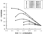
ここで、冷却ファン10の回転数制御について説明するために、図2に、冷却ファン10の定格に対する回転数比を変化させたときの、ヒートポンプ装置1の全体効率である成績係数(COP)の変化が、負荷率によってどのように異なるかをグラフに示す。なお、本実施形態においては、上述したPID制御に基づき決定されるスクリュ圧縮機2の回転数を所定の回転数、例えば3675rpmで除した値を負荷率としている。
Here, in order to explain the rotational speed control of the
図示するように、いずれの負荷率においても、ある回転数比において最大効率を示すが、負荷率が低いほど、最大効率を示すファン10の回転数比が低いことが分かる。具体的には、外気温度25℃において、最大効率を示す冷却ファン10の回転数比は、負荷率80%のときに0.8、負荷率50%のときに0.75、負荷率35%のときに0.65、負荷率25%のときにやはり0.65程度である。また、外気温度15℃において、最大効率を示すファン10の回転数比は、負荷率25%のときに0.55程度である。なお、負荷率が低いほど、最大効率を示す冷却ファン10の低いと上述したが、外気温度25度の場合には、負荷率25%以下では最大効率を示す冷却ファン10の回転数比は略一定となっている。
As shown in the figure, the maximum efficiency is shown at a certain rotation speed ratio at any load factor, but it can be seen that the lower the load factor, the lower the rotation speed ratio of the
以上の効率変化をふまえて、ヒートポンプ装置1では、外気温度25℃のデータに基づく図3に示すように、負荷率に応じて冷却ファン10の回転数を定める。具体的には、ヒートポンプ装置1は、負荷率35%以下では冷却ファン10の定格に対する回転数比を0.65に設定し、負荷率が35%を超え、50%以下のときは冷却ファン10の回転数比を0.75に設定し、負荷率が50%を超え、80%以下のときは冷却ファン10の回転数比を0.8に設定し、負荷率が80%を超えるときは冷却ファン10の回転数比を1.0に設定する。
Based on the above efficiency change, the
冷却ファン10の負荷率に応じた最適な回転数比は、破線で示すように、連続的に変化するが、ヒートポンプ装置1においては、制御の安定性などを考慮して、上記のような段階的な回転数制御を行う。尚、実際の制御において、負荷率はスクリュ圧縮機2の回転数に略比例するので、制御装置13は、圧縮機インバータ9の設定周波数に応じてファンインバータ12の設定周波数を定める。
The optimum rotation speed ratio corresponding to the load factor of the
このようにして、本実施形態のヒートポンプ装置1は、負荷率の変動に応じて、冷却ファン10の回転数を変化させることで、全体の効率を高く維持することができる。
Thus, the
さらに、本発明の異なる実施形態について説明する。
図4は、本発明の第2実施形態であるヒートポンプ装置1aを示す。このヒートポンプ装置1aは、第1実施形態のヒートポンプ装置1と多くの構成を同じくするが、さらに、蒸発器6の入口における被冷却媒体の温度を計測する温度センサ15を有している。
Further, different embodiments of the present invention will be described.
FIG. 4 shows a heat pump apparatus 1a according to the second embodiment of the present invention. The heat pump device 1a has the same configuration as the
制御装置13は、従来のヒートポンプ装置と同様に、ひいては、ヒートポンプ装置1と同様に、温度センサ14が検出する被冷却媒体の温度を予め設定された温度に保つように、圧縮機インバータ9の周波数、つまり、スクリュ圧縮機2の回転数をPID制御する。さらに、制御装置13は、温度センサ15にて検出された蒸発器6の入口における被冷却媒体の温度と、温度センサ14にて検出された蒸発器6の出口における被冷却媒体の温度との差分に応じて、冷却ファン10の回転数を制御する。
As with the conventional heat pump device, the
具体的には、蒸発器6の入口における被冷却媒体の温度(温度センサ15にて検出された温度)をTsとし、蒸発器6の出口における被冷却媒体の温度(温度センサ14にて検出された温度)をTdとし、負荷率をLとした場合、予め定められた温度TthよりTsが高くならない範囲内で、制御装置13は、負荷率LをL=(Ts−Td)/(Tth−Td)×100%で算出する。
Specifically, the temperature of the medium to be cooled at the inlet of the evaporator 6 (temperature detected by the temperature sensor 15) is Ts, and the temperature of the medium to be cooled at the outlet of the evaporator 6 (detected by the temperature sensor 14). When the load factor is L and the load factor is L, the
例えば、上記PID制御にて蒸発器6の出口における被冷却媒体の温度を7℃で一定に保つように設定され、予め定められた温度Tthが12℃である場合を考えるとTdは、理想的には7℃になるので、その理想状態にて、Tsが12℃であれば、負荷率Lは100%と算出される。同様に、Tsが11℃であれば、負荷率Lは80%、Tsが10℃であれば負荷率Lは60%、Tsが9℃であれば、負荷率Lは40%、Tsが8℃であれば、負荷率Lは20%と算出される。負荷率Lが算出されれば、ヒートポンプ装置1aは、上述のヒートポンプ装置1と同様に、図3に示すように、負荷率Lに応じて冷却ファン10の回転数と定める。
For example, when the temperature of the medium to be cooled at the outlet of the
さらに、本発明の第3実施形態について説明する。
図5は、本発明の第3実施形態のヒートポンプ装置1bを示す。このヒートポンプ装置1bは、第1実施形態のヒートポンプ装置1と多くの構成を同じくするが、さらに、凝縮器3の周囲の外気温度を計測する外気温度センサ16を有している。
Furthermore, a third embodiment of the present invention will be described.
FIG. 5 shows a
制御装置13は、従来のヒートポンプ装置と同様に、ひいては、ヒートポンプ装置1と同様に、温度センサ14が検出する被冷却媒体の温度を予め設定された温度に保つように、圧縮機インバータ9の周波数、つまり、スクリュ圧縮機2の回転数をPID制御する。
As with the conventional heat pump device, the
ところで、上述した図2に示された外気温度25℃で負荷率25%の場合の曲線と、外気温度15℃で負荷率15%の曲線を見て分かるとおり、外気温度が低下するにつれ、最大効率を示すファン10の回転数比も低下する。具体的には、上述したとおり、外気温度25℃で負荷率25%のときに0.65程度であった「最大効率を示す冷却ファン10の回転数比」は、外気温度15℃で同じ負荷率25%のときには0.55程度に低下する。
By the way, as can be seen from the above-described curve when the outside air temperature is 25 ° C. and the load factor is 25% shown in FIG. 2 and when the outside air temperature is 15 ° C. and the load factor is 15%, as the outside air temperature decreases, the maximum The rotational speed ratio of the
なお、本発明者らは、負荷率25%以外の場合であっても、外気温度が低下するにつれて「最大効率を示す冷却ファン10の回転数比」が低下することを知見した。これは、外気温度が低下してくると、主にスクリュ圧縮機2の動力と冷却ファン10の動力からなる全体動力の中で、冷却ファン10の動力の割合が大きくなってくることから、冷却ファン10の風力変化時の性能変化が大きく、最適な風量が低風量側に移行することを意味している。
Note that the present inventors have found that even when the load factor is other than 25%, the “rotational speed ratio of the cooling
本実施形態のヒートポンプ装置1bは、上述した知見に基づき、外気温度を外気温度センサ16で計測して、計測された外気温度が「所定の温度」以下に低下した場合(外気温度が低いとき)には、スクリュ圧縮機2の回転数が低いときに冷却ファン10の回転数を低くする度合いを大きくするように、逆に、外気温度が「所定の温度」以上に上昇した場合(外気温度が高いとき)には、スクリュ圧縮機2の回転数が低いときに冷却ファン10の回転数を低くする度合いを小さくするように、構成されている。なお、ここでいう前者の「所定の温度」は、後者の「所定の温度」以下であればよく、両者が同一であることは必須ではない。
The
具体的には、例えば次のとおりである。
予め、上述の図3に準じ、且つ、外気温度毎に異なるグラフ、すなわち外気温度毎に異なる複数の「負荷率と冷却ファン回転数との関係を示すグラフ」のデータ(図3、図6、図7のデータ)を制御装置13は保持する。そして制御装置13は外気温度が15℃より高く、35℃より低い場合は上述の図3に基づいて、外気温度が15℃以下の場合は図6に基づいて、外気温度が35℃以上の場合は図7に基づいて、冷却ファン10の回転数を定める。
Specifically, for example, it is as follows.
In advance, data of a plurality of “graphs showing the relationship between the load factor and the cooling fan rotational speed” that are different in accordance with the above-described FIG. The
図3、図6、図7を見て分かるとおり、外気温度にかかわらず、負荷率が低下するに従い、冷却ファン10の定格に対する回転数比は段階的に低下される。ただし、図面上の段差は、図7よりも図3、さらに図3よりも図6のほうが大きくなっている。そのことから分かるように、冷却ファン10の定格に対する回転数比が低下される場合のその低下の度合いは外気温度が低いほど大きくされている。すなわち、ここでは、外気温度が15℃以下に低下した場合には、スクリュ圧縮機2の回転数が低いときに冷却ファン10の回転数を低くする度合いを大きくするように、逆に外気温度が35℃以上に上昇した場合には、スクリュ圧縮機2の回転数が低いときに冷却ファン10の回転数を低くする度合いを小さくするように、構成されている。
As can be seen from FIGS. 3, 6, and 7, the rotation speed ratio with respect to the rating of the cooling
このように外気温度の変化を把握し、それを冷却ファン10の制御に利用するように構成することで、外気温度の変化にかかわらず、全体の効率を維持できるという利点がある。
Thus, by grasping | ascertaining the change of external temperature and utilizing it for control of the cooling
なお、第2実施形態のヒートポンプ装置1aに外気温度を計測する外気温度センサを付加し、上述の第3実施形態と同様に、外気温度を冷却ファン10の制御に利用するように構成してもよい。
Note that an outside air temperature sensor for measuring the outside air temperature may be added to the heat pump device 1a of the second embodiment, and the outside air temperature may be used for controlling the cooling
無論、「負荷率と冷却ファン回転数との関係を示すグラフ」は上述のような3つに限らず、もっと多数のデータを制御装置13が保持するようにしてもよい。また、冷却ファン10の回転数を段階的に変化させるのではなく、負荷率や外気温度の関数として、例えばPID制御などによって連続的に変化させてもよい。
Of course, the “graph showing the relationship between the load factor and the cooling fan rotation speed” is not limited to the above three, and the
なお、本発明にいうヒートポンプ装置は上述のものに限らない。上述したものは、蒸発器6において冷媒と被冷却媒体を熱交換して、冷却された被冷却媒体を活用する機能を有するものであるが、本発明にいうヒートポンプ装置はその機能のみを有するものに限定されず、いわゆる冷暖房の機能を切換可能なものであってもよい。例えば、本発明のヒートポンプ装置は、上述した図1のものに、さらに4方弁等の介設された切換流路を具備し、その4方弁等の開閉にて、冷媒循環流路の冷媒の流れを切り換えることによって、図1における凝縮器3に蒸発器の役割を担わせるとともに、図1における蒸発器6に凝縮器の役割を担わせるようにし、被冷却媒体と称している媒体を冷却するのみでなく暖めることもできるように構成したものであってもよい。
In addition, the heat pump apparatus said to this invention is not restricted to the above-mentioned thing. Although what has been described above has a function of exchanging heat between the refrigerant and the medium to be cooled in the
1,1a,1b ヒートポンプ装置
2 スクリュ圧縮機
3 凝縮器
5 膨張弁
6 蒸発器
7 冷媒循環流路
9 圧縮機インバータ
10 冷却ファン
12 ファンインバータ
13 制御装置
14 温度センサ
15 温度センサ
16 外気温度センサ
1, 1a, 1b
Claims (2)
前記凝縮器に通風する冷却ファンと、
前記被冷却媒体の前記蒸発器入口における温度を検出する温度センサと、
前記被冷却媒体の前記蒸発器出口における温度を検出する温度センサとを有し、
前記圧縮機は、前記蒸発器出口における温度に基づき、当該温度を一定に保つように回転数制御され、
負荷率に応じて、前記冷却ファンの回転数を定め、
負荷率を示す値として、前記蒸発器入口における温度と前記蒸発器出口における温度との差分を用い、
前記差分が小さくなるに従い、前記冷却ファンの回転数を低くすることを特徴とするヒートポンプ装置。 A refrigerant circulation passage in which refrigerant is enclosed, and a compressor, a condenser, an expansion valve, and an evaporator for exchanging heat between the refrigerant and the medium to be cooled are interposed;
A cooling fan that ventilates the condenser;
A temperature sensor for detecting the temperature of the cooled medium at the evaporator inlet;
A temperature sensor for detecting the temperature of the cooled medium at the outlet of the evaporator;
Based on the temperature at the evaporator outlet , the compressor is rotationally controlled to keep the temperature constant,
Depending on the load factor, the number of revolutions of the cooling fan constant because,
As a value indicating the load factor, using the difference between the temperature at the evaporator inlet and the temperature at the evaporator outlet,
The heat pump device characterized in that the number of rotations of the cooling fan is lowered as the difference becomes smaller .
計測された外気温度が低いときには、前記差分が小さいときに前記冷却ファンの回転数を低くする度合いを大きくすることを特徴とする請求項1に記載のヒートポンプ装置。 It has an outside temperature sensor that measures outside temperature,
When the measured outside air temperature is low, the heat pump apparatus according to claim 1, characterized in that to increase the degree of lowering the rotational speed of the cooling fan when the difference is smaller.
Priority Applications (1)
| Application Number | Priority Date | Filing Date | Title |
|---|---|---|---|
| JP2006003802A JP4860267B2 (en) | 2006-01-11 | 2006-01-11 | Heat pump equipment |
Applications Claiming Priority (1)
| Application Number | Priority Date | Filing Date | Title |
|---|---|---|---|
| JP2006003802A JP4860267B2 (en) | 2006-01-11 | 2006-01-11 | Heat pump equipment |
Publications (2)
| Publication Number | Publication Date |
|---|---|
| JP2007187345A JP2007187345A (en) | 2007-07-26 |
| JP4860267B2 true JP4860267B2 (en) | 2012-01-25 |
Family
ID=38342632
Family Applications (1)
| Application Number | Title | Priority Date | Filing Date |
|---|---|---|---|
| JP2006003802A Active JP4860267B2 (en) | 2006-01-11 | 2006-01-11 | Heat pump equipment |
Country Status (1)
| Country | Link |
|---|---|
| JP (1) | JP4860267B2 (en) |
Families Citing this family (5)
| Publication number | Priority date | Publication date | Assignee | Title |
|---|---|---|---|---|
| US8657207B2 (en) * | 2008-08-26 | 2014-02-25 | Lg Electronics Inc. | Hot water circulation system associated with heat pump and method for controlling the same |
| JP6264532B2 (en) * | 2013-11-01 | 2018-01-24 | 三浦工業株式会社 | Food machine with vacuum cooling function |
| JP6328004B2 (en) * | 2014-08-15 | 2018-05-23 | 株式会社大気社 | Compressor / pump switching type cooling device |
| CN107560282B (en) * | 2017-09-15 | 2019-10-22 | 珠海格力电器股份有限公司 | The control method of cooling system |
| CN113757843B (en) * | 2021-08-23 | 2023-01-31 | 浙江中广电器集团股份有限公司 | Heat pump unit suitable for air source and heating control method thereof |
Family Cites Families (5)
| Publication number | Priority date | Publication date | Assignee | Title |
|---|---|---|---|---|
| JPH0776632B2 (en) * | 1989-10-31 | 1995-08-16 | ダイキン工業株式会社 | Refrigeration system operation controller |
| JP3311432B2 (en) * | 1993-06-29 | 2002-08-05 | 三洋電機株式会社 | Speed control device for blower for condenser |
| JP3668121B2 (en) * | 2000-11-02 | 2005-07-06 | 三洋電機株式会社 | Speed adjusting device for condenser blower |
| JP4039100B2 (en) * | 2002-03-29 | 2008-01-30 | ダイキン工業株式会社 | Air conditioner |
| JP2005048973A (en) * | 2003-07-29 | 2005-02-24 | Mitsubishi Heavy Ind Ltd | Air conditioner and method of controlling the same |
-
2006
- 2006-01-11 JP JP2006003802A patent/JP4860267B2/en active Active
Also Published As
| Publication number | Publication date |
|---|---|
| JP2007187345A (en) | 2007-07-26 |
Similar Documents
| Publication | Publication Date | Title |
|---|---|---|
| US8813511B2 (en) | Control system for operating condenser fans | |
| JP4594276B2 (en) | Cold / hot water control method for cold / hot heat source machine and air conditioning system used therefor | |
| JP5907247B2 (en) | Integrated air conditioning system and its control device | |
| JP4842855B2 (en) | Air conditioner | |
| JP6570746B2 (en) | Heat medium circulation system | |
| JP4422572B2 (en) | Cold / hot water control method for cold / hot heat source machine | |
| JP4860267B2 (en) | Heat pump equipment | |
| JP5984456B2 (en) | Heat source system control device, heat source system control method, heat source system, power adjustment network system, and heat source machine control device | |
| JP2007240131A (en) | Optimization control of heat source unit and accessory | |
| JP5201183B2 (en) | Air conditioner and method of operating refrigerator | |
| CN104246397A (en) | A method of controlling one or more fans of a heat rejecting heat exchanger | |
| JP5677223B2 (en) | Air conditioner | |
| JP6594126B2 (en) | Refrigeration cycle apparatus and control method thereof | |
| WO2016098626A1 (en) | Air-conditioning device | |
| EP3674621B1 (en) | Air conditioner | |
| JP2016166710A (en) | Air-conditioning system | |
| JP2011226680A (en) | Cooling water producing facility | |
| JP5455338B2 (en) | Cooling tower and heat source system | |
| KR100826926B1 (en) | Water Cooling Type Air Conditioner and Control Method thereof | |
| JPWO2020003490A1 (en) | Air conditioner | |
| JP6937919B2 (en) | Free cooling outdoor unit | |
| WO2016199218A1 (en) | Air conditioning device | |
| JP2011033222A (en) | Water heat source air conditioning system | |
| JP6614063B2 (en) | Electric motor cooling control system | |
| JP6556339B2 (en) | Air conditioner |
Legal Events
| Date | Code | Title | Description |
|---|---|---|---|
| A621 | Written request for application examination |
Free format text: JAPANESE INTERMEDIATE CODE: A621 Effective date: 20081112 |
|
| A977 | Report on retrieval |
Free format text: JAPANESE INTERMEDIATE CODE: A971007 Effective date: 20101118 |
|
| A131 | Notification of reasons for refusal |
Free format text: JAPANESE INTERMEDIATE CODE: A131 Effective date: 20101124 |
|
| A521 | Request for written amendment filed |
Free format text: JAPANESE INTERMEDIATE CODE: A523 Effective date: 20110120 |
|
| A131 | Notification of reasons for refusal |
Free format text: JAPANESE INTERMEDIATE CODE: A131 Effective date: 20110517 |
|
| A521 | Request for written amendment filed |
Free format text: JAPANESE INTERMEDIATE CODE: A523 Effective date: 20110705 |
|
| TRDD | Decision of grant or rejection written | ||
| A01 | Written decision to grant a patent or to grant a registration (utility model) |
Free format text: JAPANESE INTERMEDIATE CODE: A01 Effective date: 20111004 |
|
| A01 | Written decision to grant a patent or to grant a registration (utility model) |
Free format text: JAPANESE INTERMEDIATE CODE: A01 |
|
| A61 | First payment of annual fees (during grant procedure) |
Free format text: JAPANESE INTERMEDIATE CODE: A61 Effective date: 20111102 |
|
| R150 | Certificate of patent or registration of utility model |
Free format text: JAPANESE INTERMEDIATE CODE: R150 Ref document number: 4860267 Country of ref document: JP Free format text: JAPANESE INTERMEDIATE CODE: R150 |
|
| FPAY | Renewal fee payment (event date is renewal date of database) |
Free format text: PAYMENT UNTIL: 20141111 Year of fee payment: 3 |
|
| R250 | Receipt of annual fees |
Free format text: JAPANESE INTERMEDIATE CODE: R250 |
|
| R250 | Receipt of annual fees |
Free format text: JAPANESE INTERMEDIATE CODE: R250 |
|
| S533 | Written request for registration of change of name |
Free format text: JAPANESE INTERMEDIATE CODE: R313533 |
|
| R350 | Written notification of registration of transfer |
Free format text: JAPANESE INTERMEDIATE CODE: R350 |
|
| R250 | Receipt of annual fees |
Free format text: JAPANESE INTERMEDIATE CODE: R250 |
|
| R250 | Receipt of annual fees |
Free format text: JAPANESE INTERMEDIATE CODE: R250 |
|
| R250 | Receipt of annual fees |
Free format text: JAPANESE INTERMEDIATE CODE: R250 |
|
| R250 | Receipt of annual fees |
Free format text: JAPANESE INTERMEDIATE CODE: R250 |
|
| R250 | Receipt of annual fees |
Free format text: JAPANESE INTERMEDIATE CODE: R250 |
|
| S111 | Request for change of ownership or part of ownership |
Free format text: JAPANESE INTERMEDIATE CODE: R313115 |
|
| S531 | Written request for registration of change of domicile |
Free format text: JAPANESE INTERMEDIATE CODE: R313531 |
|
| R350 | Written notification of registration of transfer |
Free format text: JAPANESE INTERMEDIATE CODE: R350 |
|
| R250 | Receipt of annual fees |
Free format text: JAPANESE INTERMEDIATE CODE: R250 |
|
| R250 | Receipt of annual fees |
Free format text: JAPANESE INTERMEDIATE CODE: R250 |
|
| R250 | Receipt of annual fees |
Free format text: JAPANESE INTERMEDIATE CODE: R250 |