JP4856552B2 - Method for coating paper / paperboard with curtain coater - Google Patents
Method for coating paper / paperboard with curtain coater Download PDFInfo
- Publication number
- JP4856552B2 JP4856552B2 JP2006553609A JP2006553609A JP4856552B2 JP 4856552 B2 JP4856552 B2 JP 4856552B2 JP 2006553609 A JP2006553609 A JP 2006553609A JP 2006553609 A JP2006553609 A JP 2006553609A JP 4856552 B2 JP4856552 B2 JP 4856552B2
- Authority
- JP
- Japan
- Prior art keywords
- coating
- coating material
- supply
- thickness
- web
- Prior art date
- Legal status (The legal status is an assumption and is not a legal conclusion. Google has not performed a legal analysis and makes no representation as to the accuracy of the status listed.)
- Expired - Fee Related
Links
- 238000000576 coating method Methods 0.000 title claims description 241
- 239000011248 coating agent Substances 0.000 title claims description 239
- 238000000034 method Methods 0.000 title claims description 34
- 239000000123 paper Substances 0.000 title claims description 13
- 239000011087 paperboard Substances 0.000 title claims description 10
- 239000000463 material Substances 0.000 claims description 116
- 230000001105 regulatory effect Effects 0.000 claims description 34
- 238000004891 communication Methods 0.000 claims description 4
- 238000007766 curtain coating Methods 0.000 claims 5
- 239000010410 layer Substances 0.000 description 85
- 238000005259 measurement Methods 0.000 description 10
- 239000011247 coating layer Substances 0.000 description 9
- 239000002356 single layer Substances 0.000 description 6
- 230000007547 defect Effects 0.000 description 4
- 230000008901 benefit Effects 0.000 description 2
- 238000013461 design Methods 0.000 description 2
- 239000012467 final product Substances 0.000 description 2
- 230000033001 locomotion Effects 0.000 description 2
- 239000000047 product Substances 0.000 description 2
- 238000009825 accumulation Methods 0.000 description 1
- 230000015572 biosynthetic process Effects 0.000 description 1
- 230000008602 contraction Effects 0.000 description 1
- 230000001276 controlling effect Effects 0.000 description 1
- 238000012937 correction Methods 0.000 description 1
- 230000003247 decreasing effect Effects 0.000 description 1
- 230000001419 dependent effect Effects 0.000 description 1
- 238000010586 diagram Methods 0.000 description 1
- 238000001035 drying Methods 0.000 description 1
- 230000002427 irreversible effect Effects 0.000 description 1
- 238000004519 manufacturing process Methods 0.000 description 1
- 238000000691 measurement method Methods 0.000 description 1
- 239000000203 mixture Substances 0.000 description 1
- 238000005457 optimization Methods 0.000 description 1
- 238000012856 packing Methods 0.000 description 1
- 239000013049 sediment Substances 0.000 description 1
- 238000004062 sedimentation Methods 0.000 description 1
- 238000003860 storage Methods 0.000 description 1
- 230000002459 sustained effect Effects 0.000 description 1
Images


Classifications
-
- D—TEXTILES; PAPER
- D21—PAPER-MAKING; PRODUCTION OF CELLULOSE
- D21H—PULP COMPOSITIONS; PREPARATION THEREOF NOT COVERED BY SUBCLASSES D21C OR D21D; IMPREGNATING OR COATING OF PAPER; TREATMENT OF FINISHED PAPER NOT COVERED BY CLASS B31 OR SUBCLASS D21G; PAPER NOT OTHERWISE PROVIDED FOR
- D21H23/00—Processes or apparatus for adding material to the pulp or to the paper
- D21H23/02—Processes or apparatus for adding material to the pulp or to the paper characterised by the manner in which substances are added
- D21H23/22—Addition to the formed paper
- D21H23/46—Pouring or allowing the fluid to flow in a continuous stream on to the surface, the entire stream being carried away by the paper
- D21H23/48—Curtain coaters
Landscapes
- Coating Apparatus (AREA)
- Paper (AREA)
- Application Of Or Painting With Fluid Materials (AREA)
Description
本発明は、カーテン塗工機で紙/板紙を塗工する方法に関し、当該方法は、ノズルビームの使用を含み、ノズルビームは、塗工されるべきウェブに亘って延在する長さを有するよう構成され、且つ、カーテン塗工機の長さ方向に延在し且つ供給素子によって塗工材料を備える少なくとも2つの供給室と、供給室と流れ連絡するノズルスロットとを含むノズルユニットとを含み、供給室は、カーテン塗工機の長さ方向に延在し、且つ、各供給室から供給され且つノズルスロットの出口孔からさらに放出される塗工材料も有し、当該方法は、少なくとも2つの塗工材料層から成る塗工の使用を含む。本発明は、上記方法を実施するための構成にも関する。本発明は、全体的厚さの制御の向上、及び、紙/板紙ウェブの塗工ペーストを塗布する目的のカーテン塗工機の塗工層における横方向プロファイルの規制可能性の向上に向けられている。 The present invention relates to a method of coating paper / paperboard with a curtain coater, the method comprising the use of a nozzle beam, the nozzle beam having a length extending over the web to be coated. And a nozzle unit comprising at least two supply chambers extending in the length direction of the curtain coater and provided with coating material by a supply element, and nozzle slots in flow communication with the supply chamber The supply chambers extend in the length direction of the curtain coater and also have a coating material supplied from each supply chamber and further discharged from the outlet hole of the nozzle slot, the method comprising at least 2 Includes the use of a coating consisting of two coating material layers. The invention also relates to a configuration for carrying out the method. The present invention is directed to improving the overall thickness control and to improving the controllability of the transverse profile in the coating layer of a curtain coater for the purpose of applying a paper / board web coating paste. Yes.
カーテン塗工機をスロット供給及び平面供給塗工機として特定し得る。本発明は、具体的には、平面供給塗工機に向けられている。それはノズルを用いて塗工材料を傾斜面上に供給することを含み、それは傾斜面に沿って平面のリップに向かって流れ、塗工としてカーテンが平面のリップから落ちる。結果として得られる塗工材料のカーテンは、エッジガイドによって制御され、エッジガイドは、その名前によって示唆されるように、供給リップの縁部に位置する。 Curtain coaters may be identified as slot feed and flat feed coaters. The present invention is specifically directed to a flat feed coating machine. It involves using a nozzle to feed the coating material onto the inclined surface, which flows along the inclined surface toward the planar lip, and as a coating the curtain falls from the planar lip. The resulting curtain of coating material is controlled by an edge guide, which is located at the edge of the supply lip, as suggested by its name.
従来技術のカーテン塗工機の問題は、様々な運転条件において、塗工されるウェブへの塗工材料の塗布のために、塗工材料の横方向プロファイルを制御することに関する。塗工プロファイルに亘る有効且つ活性的な制御をもたらす従来的な手段はない。 A problem with prior art curtain coaters relates to controlling the lateral profile of the coating material for application of the coating material to the web to be coated at various operating conditions. There is no conventional means of providing effective and active control over the coating profile.
供給通路の形状が決定されるときに、塗工の全体的プロファイルを塗工ビームの設計段階において影響し得ることが先行的に知られている。塗工材料の特性及び/又は供給量が後続して変化するとき、変化は横方向プロファイルに明確な影響を有し、もはやそれを補正し得ない。製造における不正確性は、プロファイルに対する類似の不可逆的な影響を有する。 It is known in advance that the overall profile of the coating can be influenced during the coating beam design stage when the shape of the supply passage is determined. When the properties of the coating material and / or the feed rate subsequently change, the change has a clear influence on the lateral profile and can no longer be corrected for it. Inaccuracies in manufacturing have a similar irreversible effect on the profile.
単一層のための合理的に良好な横方向プロファイルを提供するために、実験的に或いは数理的に事前決定されたバイパス量を用いることによって規制することも可能である。バイパスという用語は、供給室内に供給される塗工材料の流れの一部を指し、それは供給室の他の下流端部から供給ビン又は貯蔵ビンに戻される。塗工材料バイパスの目的は、所与の最低量を超える塗工材料の流量が、ノズルユニット内の流れ通路内で、並びに、塗工材料の流れに面するその端部内で持続されることを保証することである。これの目的は、塗工材料の沈澱、及び、流れ通路の壁上の沈殿物の蓄積を回避することである。塗工材料の割合は変化するので、このバイパス量は、補正因数を用いることによって矯正されなければならない。これらは例えば粘度及び乾燥含有率の変化に起因する誤差の補償をもたらす。しかしながら、測定及び規制の角度はそのような適度なレベルにあり得るので、所望のプロファイルを全ての運転条件において制御された方法で得ることができない。 In order to provide a reasonably good lateral profile for a single layer, it is also possible to regulate by using an experimentally or mathematically predetermined amount of bypass. The term bypass refers to a part of the flow of coating material supplied into the supply chamber, which is returned from the other downstream end of the supply chamber to the supply or storage bin. The purpose of the coating material bypass is to ensure that the flow rate of coating material above a given minimum amount is sustained in the flow passage in the nozzle unit, as well as in its end facing the flow of coating material. It is to guarantee. The purpose of this is to avoid sedimentation of the coating material and accumulation of sediment on the walls of the flow passage. Since the proportion of coating material varies, this amount of bypass must be corrected by using a correction factor. These provide compensation for errors due to, for example, changes in viscosity and dry content. However, because the measurement and regulation angles can be at such reasonable levels, the desired profile cannot be obtained in a controlled manner at all operating conditions.
他方、フィンランド国特許出願番号第FI20035149号は、正に特定の等級の塗工材料及び供給量のためにノズル放出塗工の横方向プロファイルを最適化することを可能にする構成を開示している。加えて、かなりの範囲内でさえ最適化を遂行し得る。しかしながら、この最適化された供給量から逸脱するとき、或いは、塗工材料の特性に変更が行われるとき、横方向プロファイルは再び不完全になる。 On the other hand, Finnish Patent Application No. FI20035149 discloses a configuration that makes it possible to optimize the lateral profile of the nozzle discharge coating for exactly a certain grade of coating material and feed rate. . In addition, optimization can be performed even within a considerable range. However, when deviating from this optimized feed rate or when changes are made to the properties of the coating material, the transverse profile becomes imperfect again.
塗工の均質性及び全体的プロファイルに関して、最も深刻な問題は、それにも拘わらず並びにとりわけ、紙/板紙ウエブの塗工が、1つよりも多い塗工材料の層によってしばしば遂行されるという事実である。各個別層は独自の特定の横方向プロファイルを有し、それは、順次、例えば、この特定層のための塗工材料の全体的供給量に依存する。多層塗工プロセスの場合には、塗工材料の供給量の変化は、全ての層の横方向プロファイルが傾き、さらに、同一方向においてさえ傾くという条件を発展しそうであり、よって、塗工の全体的プロファイルは全ての要件をもはや満足しない。 With regard to coating homogeneity and overall profile, the most serious problems are nevertheless and, inter alia, the fact that the coating of paper / paperboard webs is often carried out by more than one layer of coating material It is. Each individual layer has its own specific lateral profile, which in turn depends, for example, on the overall supply of coating material for this specific layer. In the case of a multi-layer coating process, a change in the supply of coating material is likely to develop the condition that the lateral profile of all layers is tilted and even tilted in the same direction, thus the entire coating. Dynamic profile no longer satisfies all requirements.
よって、これらの様々な上述された有害因子の組み合わせの結果は、塗工の全体的プロファイルが、許容し得ないほど不十分にさえなり得ることである。従って、本発明の目的は、塗工機を用いて紙/板紙を塗工する方法の改良を提供することであり、該方法は、塗工されるべきウェブの横方向でノズルユニットの全長に沿った一定の塗工の形成を可能にし、且つ、運転中、様々な塗工材料及び供給量の効果的且つ迅速な規制可能性も可能にする。 Thus, the result of the combination of these various above-mentioned harmful factors is that the overall profile of the coating can even be unacceptably inadequate. Accordingly, it is an object of the present invention to provide an improved method of coating paper / paperboard using a coating machine, which can be applied to the overall length of the nozzle unit in the lateral direction of the web to be coated. It enables the formation of a consistent coating along the line and also allows for effective and rapid regulation of various coating materials and feed rates during operation.
この目的を達成するために、本発明の方法は、塗工の全体的厚さ及び横方向プロファイルが、少なくとも1つの塗工材料層の厚さを調節することによって制御され、少なくとも1つの塗工材料層は、紙/板紙ウェブ上の塗工の総量を決定するために、単独で或いは一緒に、塗工の総量の少なくとも40%を提供すること、並びに、塗工材料の決定された量は、塗工のための所望の全体的厚さ及び横方向プロファイルを達成するために横ウェブ方向にプロファイル化されるときに、少なくとも1つの塗工材料層の厚さを規制するための基礎として用いられることを特徴とする。他方、本発明の構成は、該構成が、紙/板紙ウェブからの塗工の総量を決定するために、繊維状ウェブに関連して配置される測定素子と、少なくとも1つの塗工材料層の厚さを調節するための規制素子とを含み、少なくとも1つの塗工材料層は、塗工のための所望の全体的な厚さ及び横方向プロファイルを達成するために横ウェブ方向においてプロファイル化されるときに、単独で或いは一緒に、塗工の総量の少なくとも40%を提供することを特徴とする。 To achieve this goal, the method of the present invention is such that the overall thickness and lateral profile of the coating is controlled by adjusting the thickness of the at least one coating material layer, so that at least one coating is applied. The material layer provides, alone or together, at least 40% of the total amount of coating to determine the total amount of coating on the paper / board web, and the determined amount of coating material is Used as a basis for regulating the thickness of at least one coating material layer when profiled in the transverse web direction to achieve the desired overall thickness and transverse profile for the coating It is characterized by being able to. On the other hand, the configuration of the present invention comprises a measuring element disposed in relation to the fibrous web and at least one coating material layer for determining the total amount of coating from the paper / paperboard web. And at least one coating material layer is profiled in the transverse web direction to achieve the desired overall thickness and transverse profile for coating. At least 40% of the total amount of coating, alone or together.
故に、本発明は、ウェブ表面から塗工の総量を決定し、供給室と供給スロットとの間の塗工材料流れの収縮を実現するために測定結果を使用し、それによって、塗工材料の少なくとも1つの層に関して、塗工材料流量の規制を自動化することに基づく。 Thus, the present invention determines the total amount of coating from the web surface and uses the measurement results to achieve shrinkage of the coating material flow between the supply chamber and the supply slot, thereby reducing the coating material Based on automating the regulation of the coating material flow rate for at least one layer.
塗工材料の単一層の厚さを運転中に横ウェブ方向において局所的に調節し、それによって、塗工の全体的厚さに関する所望の規制を達成し得る。この脈絡において、規制の局所的性質は、調節を横ウェブ方向における所望間隔で、具体的には、他の間隔に拘わらずに可能にすることに関してである。よって、換言すれば、横ウェブ方向におけるプロファイルの他の地域に拘わらずに、塗工プロファイルの調節をそのような各間隔のために所望値に実現し得る。 The thickness of the single layer of coating material can be adjusted locally in the transverse web direction during operation, thereby achieving the desired regulation for the overall thickness of the coating. In this context, the local nature of the regulation is with respect to allowing adjustment at the desired interval in the transverse web direction, specifically regardless of other intervals. Thus, in other words, adjustment of the coating profile can be achieved to a desired value for each such interval, regardless of other regions of the profile in the transverse web direction.
方法における基本的な目的は、一貫した横方向プロファイルを提供することである。本質的なことは、塗工材料の流量のための規制は、測定された全体的な塗工の厚さに基づき遂行され、具体的には、そこに検出される相対的欠陥又は横方向プロファイルの不一致に基づいて遂行される。例えば、ウェブに亘って延在する測定装置を用いて、横方向塗布プロファイルの測定を遂行し得る。本発明によって得られる1つの本質的な利益は、塗工材料の種類が規制及びその正確性に関連性を有しないことである。 The basic purpose of the method is to provide a consistent lateral profile. In essence, the regulation for the flow rate of the coating material is carried out on the basis of the measured overall coating thickness, in particular relative defects or lateral profiles detected there. Carried out on the basis of the discrepancy. For example, measurement of the lateral application profile may be performed using a measuring device that extends across the web. One essential benefit gained by the present invention is that the type of coating material is not related to regulation and its accuracy.
その上、流量の収縮が、具体的には、塗工の総量の少なくとも半分を構成するような層に関して遂行されるので、そのような規制された塗工材料層の厚さにおける小さな相対的な変更さえも、全体的な塗工の厚さにおいて検出された不一致を矯正するのに十分である。高い確度で所望の横方向塗工プロファイルをもたらすために、単一層の塗工材料のみの調節で十分である。 Moreover, since the flow rate shrinkage is carried out specifically for a layer that constitutes at least half of the total amount of coating, a small relative thickness in the thickness of such a regulated coating material layer. Even the change is sufficient to correct any discrepancies detected in the overall coating thickness. Adjustment of only a single layer of coating material is sufficient to provide the desired lateral coating profile with high accuracy.
塗工材料は、ウェブ構造内に吸収されるようになる強い傾向を多かれ少なかれ常に有するので、本発明の方法の目的として引用された所望の全体的塗工厚さ及び横方向プロファイルは、早くも平面上で極めて明らかになる。よって、実際のウェブにおける結果は、所望の塗工及びウェブの組み合わせであり、そこでは、特に、その量、厚さ、及び、横方向プロファイルに関して、塗工は所望の特性を有する。 Since the coating material always has a more or less strong tendency to become absorbed into the web structure, the desired overall coating thickness and transverse profile quoted for the purposes of the method of the present invention is as early as possible. It becomes very clear on the plane. Thus, the result in an actual web is the desired coating and web combination, where the coating has the desired properties, particularly with respect to its amount, thickness, and transverse profile.
従って、規制された塗工材料層のための塗工材料の量は、好ましくは、ウェブに塗布される塗工の総量の少なくとも40%よりも多くを構成するようにされる。よって、塗工の量は、具体的には、塗工の乾燥含有量に関連して、この脈絡で用いられる。塗工材料は、塗布前にノズルビームの平面上に供給されるので、塗工材料は、典型的には、70%未満の乾燥含有量を有する。完成商品において、即ち、抄紙機/板紙機から現れるウェブにおいて、容量に対する塗工の総量は、実質的により小さい。 Accordingly, the amount of coating material for the regulated coating material layer is preferably made up to constitute at least 40% of the total amount of coating applied to the web. Thus, the amount of coating is specifically used in this context in relation to the dry content of the coating. Since the coating material is supplied on the plane of the nozzle beam before application, the coating material typically has a dry content of less than 70%. In the finished product, i.e. the web emerging from the paper machine / board machine, the total amount of coating to capacity is substantially smaller.
塗工全体内の乾燥物質の量に関して本発明の方法において規制される層内の乾燥物質の量も、好ましくは、半分よりも多い。本来的に、本発明の方法は、決して塗工材料中の如何なる具体的な乾燥物質含有量にも限定されないことがさらに強調されなければならない。 The amount of dry matter in the layer that is regulated in the method of the invention with respect to the amount of dry matter in the overall coating is also preferably more than half. Inherently, it should be further emphasized that the method of the invention is in no way limited to any specific dry matter content in the coating material.
塗工の容量、他方、塗布の瞬間にウェブの上に塗布される厚さは、正比例で相互に相関する。しかしながら、一部の塗工は塗布後に概ねウェブ構造中に吸収されるので、ウェブ自体の表面上の塗工混合物からのみ成る層の厚さは、完成製品において、塗工の総量によって定められる全体的な塗工の厚さともはや等しくないことが、この関係で留意されるべきである。よって、塗工材料及びウェブは、互いに部分的に一体化する感じである。 The volume of coating, on the other hand, the thickness applied on the web at the moment of application is directly proportional to each other. However, since some coatings are generally absorbed into the web structure after application, the thickness of the layer consisting only of the coating mixture on the surface of the web itself is determined by the total amount of coating in the finished product. It should be noted in this connection that the typical coating thickness is no longer equal. Therefore, the coating material and the web feel that they are partially integrated with each other.
他方、塗布前のノズルビームの表面上の状況を考えるとき、例えば塗工の総量の50%は、運転中、ウェブの全幅に亘る塗工材料層の平均厚さに関して、全体的な塗工の厚さの対応する部分も示す。その結果、もし単一の塗工材料層中の塗工材料の量が、例えば、塗工の総量の半分であるならば、塗工材料も、塗工の全体的厚さのほぼ半分である平均的な厚さを有する。例えば、単一の規制された塗工材料層の場合、この単一の塗工材料層も、全体的な塗工厚さの約半分を構成する。 On the other hand, when considering the situation on the surface of the nozzle beam prior to application, for example, 50% of the total amount of coating is in operation with respect to the average thickness of the coating material layer over the entire width of the web during operation. The corresponding part of thickness is also shown. As a result, if the amount of coating material in a single coating material layer is, for example, half of the total amount of coating, the coating material is also approximately half of the overall thickness of the coating. Have an average thickness. For example, in the case of a single regulated coating material layer, this single coating material layer also constitutes about half of the overall coating thickness.
従って、規制された材料層中の塗工材料の量が、本発明に従って、塗工の総量の好ましくは40%よりも多くを正に構成するとしても、それにも拘わらず、横方向塗工プロファイルは、この規制された塗工材料層が、全体的な塗工厚さに関して、この数値に達しない地点を局所的に示し得る。よって、全体的な塗工プロファイルに現れる誤差は、この単一層の厚さを横ウェブ方向において規制することによって矯正され、それ故に、本発明の方法では、塗工層の横方向プロファイルのある地点で、その厚さが全体的な塗工厚さの前記数値よりも低い値に局所的に調節されることが可能である。しかしながら、この場合でさえも、塗工材料層は、殆どのウェブ幅の上で、全体的な塗工厚さの40%を越える厚さを有する。 Thus, although the amount of coating material in the regulated material layer constitutes positive according to the invention, preferably more than 40% of the total coating amount, it is nevertheless a transverse coating profile Can locally indicate points where this regulated coating material layer does not reach this value in terms of overall coating thickness. Thus, errors appearing in the overall coating profile are corrected by regulating the thickness of this single layer in the transverse web direction and, therefore, in the method of the present invention, a point in the transverse profile of the coating layer. Thus, the thickness can be locally adjusted to a value lower than the value of the overall coating thickness. However, even in this case, the coating material layer has a thickness of over 40% of the overall coating thickness over most web widths.
本発明の好適実施態様が従属請求項2乃至7に示される。その詳細、特徴、及び、利点に関して、本発明は、例示的な実施態様の以下の記載において、並びに、添付の図面において、より精密に例証される。 Preferred embodiments of the invention are given in the dependent claims 2 to 7. With regard to its details, features, and advantages, the present invention will be illustrated more precisely in the following description of exemplary embodiments and in the accompanying drawings.
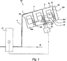
図1を参照すると、紙/板紙ウェブを塗工するための本発明の方法を適用した構成が基本的に示されている。本発明のこの実施態様は塗布ビーム40を用い、塗布ビームは、ウェブWに対するその塗布のための塗工カーテン4を形成し得る。本実施態様において、塗布ビーム40は3つの供給室12を備え、塗工材料が、等化室13,13bを経由して、3つの供給室から各ノズルスロット30に供給される。供給室12は、選択的に、塗工材料バイパスのためのバイパス経路(図示せず)を備える。
Referring to FIG. 1, there is basically shown a configuration applying the method of the present invention for coating a paper / paperboard web. This embodiment of the invention uses a coating beam 40 that can form a coating curtain 4 for its coating on the web W. In this embodiment, the coating beam 40 includes three
よって、本実施態様では、塗工カーテン4は、3つの個々の塗工材料層1,2,3から構成される(図1)。ノズルスロット30から放出され、且つ、ノズルビームの頂面35に沿って滑動する重ね合わされた塗工材料層1,2,4は、塗工カーテン4を形成するために、塗布ビームの縁部33によって構成される供給リップの上で案内される。
Therefore, in this embodiment, the coating curtain 4 is comprised from the three individual coating material layers 1, 2, and 3 (FIG. 1). Overlapping coating material layers 1, 2, 4, emanating from nozzle slot 30 and sliding along nozzle beam
基層1及び上層3の双方のために実現され且つウェブWに塗布される塗工材料の量は、ノズルビーム40に到達する塗工材料の全体的な流量と、そこから調節されるバイパス流量との間の差として得られる。塗工材料の供給量のための測定値は、塗工材料の各個別層のためにもたらされる。測定された流量は、基層1及び上層3のための供給量を所望に調節するための基礎として用いられる。 The amount of coating material realized for both the base layer 1 and the top layer 3 and applied to the web W depends on the overall flow rate of the coating material reaching the nozzle beam 40 and the bypass flow rate adjusted therefrom. Obtained as the difference between. A measurement for the supply of coating material is provided for each individual layer of coating material. The measured flow rate is used as a basis for adjusting the feed rates for the base layer 1 and the upper layer 3 as desired.
全体的な横方向プロファイルは、運転中に、塗工材料の任意の個別の層の厚さを局所的に規制することによって制御される。規制は、好ましくは、ウェブの幅全体に亘って行われる。本発明のこの例示的な実施態様において、局所的規制に晒されるその厚さを有する層として働くのは、3つの塗工材料層の中間層2である。本来的に、中間層の代わりに、個々の塗工材料層の任意の他の1つに対して規制を行うことが可能である。同様に、局所的に規制される層の数は1つより多くてもよい。規制される塗工層又は複数の塗工層の選択に関して本質的なことは、規制されるべき関連層又は複数の関連層が、全体として、塗工の総量の十分に大きな部分を構成し、それによって、塗工の全体的厚さの十分に大きな部分も構成することである。これは、規制される層の厚さに対する単に適度の局所的変更を用いてでさえ、全体的プロファイルのための十分に正確且つ効果的な制御をもたらすことを可能にする。 The overall lateral profile is controlled by locally regulating the thickness of any individual layer of coating material during operation. The regulation is preferably done across the entire width of the web. In this exemplary embodiment of the invention, it is the intermediate layer 2 of the three coating material layers that serves as a layer having that thickness that is subject to local regulation. In essence, it is possible to regulate against any other one of the individual coating material layers instead of the intermediate layer. Similarly, the number of locally restricted layers may be greater than one. What is essential regarding the choice of the coating layer or layers to be regulated is that the relevant layer or layers to be regulated as a whole constitutes a sufficiently large part of the total amount of coating, This also constitutes a sufficiently large part of the overall thickness of the coating. This makes it possible to provide sufficiently accurate and effective control for the overall profile even with just a moderate local change to the regulated layer thickness.
この場合、規制される中間層のための塗工の総量は、他の層のためのと同様である、即ち、議論される層のための塗工材料の全体的な供給量とバイパス量との間の差として計算可能であることが分かる。塗工材料の初期的な総量をこれに基づいて正しく設定し得る。中間層の厚さのための局所的規制は、ウェブWの表面から決定される塗工量に従って行われる。ウェブ上の塗工の総量の決定は、ここでは、ウェブ表面からの直接的な測定によって、或いは、例えば、ウェブの厚さとウェブ及び塗工から成る全体的厚さとの間の差としてそれを決定することによって行われ得る。 In this case, the total amount of coating for the regulated intermediate layer is the same as for the other layers, i.e. the overall supply of coating material and the bypass amount for the layer being discussed. It can be seen that the difference between can be calculated. The initial total amount of coating material can be set correctly based on this. The local regulation for the thickness of the intermediate layer is performed according to the coating amount determined from the surface of the web W. The determination of the total amount of coating on the web is here determined either by direct measurement from the web surface or, for example, as the difference between the web thickness and the overall thickness of the web and coating. Can be done by doing.
例えば、ウェブに亘って延在する測定装置41によって、塗工の全体的な厚さをウェブから測定し得る。このようにして、所望の全体的な厚さからの偏差が得られる。測定装置41によって提示される測定結果は、測定地点からノズルビーム40に提供されるフィードバックを用いることによって、中間層2のための塗工材料の供給量を規制するための基礎として用いられる。受信された測定データは、先ず、自動アクチュエータ42に送信される。アクチュエータは、次に、素子19を動作する。素子は、ノズルビーム40内に配置され、且つ、塗工材料の流れに対してさらなる直接的な影響をもたらす。
For example, the overall thickness of the coating can be measured from the web by a measuring
このように、中間層の厚さのための局所的な微調節は、運転中に供給室12から供給スロット30への塗工材料の流れを操作することによって行われる。図1の実施態様において、流れは、供給室12と供給スロット30との間の流れ通路の有効領域を変更することによって規制される。供給量の調節は、ここでは、供給室12と供給スロット30との間に設けられた等化室13の近傍において行われる。塗工材料の流れは、供給室12と等化室13との間に設けられた供給孔18内に収縮される。
In this way, local fine adjustment for the thickness of the intermediate layer is made by manipulating the flow of coating material from the
各供給孔18は、ノズル素子の外部に開口し且つ供給孔18の垂直区画に合流する穿孔19aで形成される。塗工材料の流れは、制御素子として機能する調節ピン19によって収縮される。各規制ロッド19は、そのような穿孔19a内への長さ方向の移動のために構成されている。それによって、前記調節ピンは、前記アクチュエータ42によって直接的に動作される。
Each
規制ロッドは、供給孔18内に延びる、好ましくは、傾けられた内端部23を有する。規制ロッド19は、パッキング22によって、穿孔19a内で封止される。供給孔18は、ノズル素子の長さ方向に(故に、図1の表示面に対して垂直に)、例えば、50〜600mm、好ましくは150〜300mmの相互距離を有する。その結果、前記供給孔間の間隔間隙に適合する確度で、塗工層の厚さを局所的に操作し得る。よって、それぞれに、全体的な塗工厚さは、実質的に均等な確度で調節可能でもある。
The restricting rod has an inner end 23 which preferably extends into the
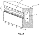
明瞭性のためにノズルビーム組立体の1つのノズル素子39のみを描写する図2の実施態様において、塗工材料供給量の規制は、順次、等化室13内に配置されたプロファイリング部材15によって、並びに、同様に動作する規制シャンク16によって行われる。よって、この実施態様において、アクチュエータ42は、これらの素子15,16に接続されている。
In the embodiment of FIG. 2 depicting only one
プロファイリング部材15は、連続的な供給孔によって定められる距離に亘って延在する供給孔14を備える等化室の表面上に位置している。矢印Dによって指し示される方向における横位置に関してプロファイリング部材15を調節することによって、流れ通路の有効領域を今や変更し得る。単一の供給孔又は幾つかの供給孔の群のいずれかに関して、供給孔のサイズを操作するためにバーを使用することによって、ノズルビームの長手方向において供給室12から等化室13への塗工材料の流量を局所的に規制し得る。規制素子として機能する規制シャンク16は、ノズルビームの長手方向に、即ち、横方向塗工プロファイルの方向に相互間隔を有し、それは、例えば、100〜600mm、好ましくは150〜300mmである。
The profiling
例えば、図1及び2に描写されるようなノズルビーム構造及び組立体を使用することによって、中間層を局所的な調節に晒すことは、他の層によって引き起こされる所望の塗工厚さからの全体的な偏差を補償することを可能にする。よって、横方向塗工プロファイルに所望の形状を与え、全体的な塗工厚さに所望値を与え得る。従って、単一の塗工材料層の厚さにおいて特定の一定値を与える努力することは、本発明の方法の目的ではなく、その代わり、横ウェブ方向における特定地点で所望の全体的な塗工厚さを得るために、その厚さを局所的に調節することである。厚さに関して局所的に規制されるべき塗工層、故にこの場合には中間層は、一種の制御バッファとして機能し、その幅を規制の範囲と見做し得る。よって、本方法は、様々な運動条件において並びに効果的な方法で、個々の塗工材料層の横方向プロファイルが正しい構成にあるか否かに拘わらず、所望の全体的な塗工プロファイルの達成を可能にする。 For example, by using a nozzle beam structure and assembly as depicted in FIGS. 1 and 2, subjecting the intermediate layer to local adjustments from the desired coating thickness caused by the other layers. Makes it possible to compensate for the overall deviation. Thus, a desired shape can be given to the lateral coating profile and a desired value can be given to the overall coating thickness. Thus, it is not the purpose of the method of the present invention to strive to give a certain constant value in the thickness of a single coating material layer, but instead the desired overall coating at a specific point in the transverse web direction. To obtain the thickness, the thickness is adjusted locally. The coating layer to be locally regulated with respect to the thickness, and in this case the intermediate layer, functions as a kind of control buffer, and its width can be regarded as a regulation range. The method thus achieves the desired overall coating profile regardless of whether the lateral profiles of the individual coating material layers are in the correct configuration as well as in a variety of motion conditions. Enable.
本発明の1つのさらなる着想によれば、バイパス量の規制を追加的に使用することによって規制を強化し得る。いずれにもそれぞれ、具体的には、近似レベルで、横方向プロファイルを調節するために、並びに、塗工材料の供給流れの自動化された収縮を用いて微調節を遂行するために、塗工材料のバイパスの増減を用い得る。よって、補助的規制としてバイパスを使用することによって、供給室とノズルスロットとの間の流量を規制する必要を軽減することが可能である。 According to one further idea of the invention, the regulation can be strengthened by additionally using a regulation of the bypass amount. In each case, specifically the coating material, at an approximate level, to adjust the lateral profile, as well as to perform the fine adjustment using the automated contraction of the coating material feed flow. An increase or decrease of bypass can be used. Thus, by using a bypass as an auxiliary restriction, it is possible to reduce the need to restrict the flow rate between the supply chamber and the nozzle slot.
本発明の方法において本質的なことは、成功的な規制が、たった1つの塗工材料層の厚さを操作することによって達成されること、さらに、そのような方法においてさえ、規制された層の厚さプロファイルに対する小さな変更だけで、成功的な規制が達成されることである。例えば、前記の例示的な実施態様におけるような三層塗工において、頂層及び底層上の塗工の量は、典型的には、2〜4g/m2と小さくあるよう構成される。この場合、規制層として機能する中間層は、典型的には、8〜15g/m2の著しくより高い厚さを有するよう選択される。この故に、頂層及び底層における高い割合の変更さえも、所望の全体的な塗工プロファイルをもたらす中間層における大きな補償変更を必要としない。被規制層として機能する塗工材料層又は複数の塗工材料層上の塗工の量は、塗工材料層上の塗工の総量の少なくとも40%を構成する。好ましくは、被規制層上の塗工材料の量は、塗工の総量の50〜80%である。それぞれ、もし厚さに関して規制されるべき1つの塗工材料層のみがあるならば、規制される層の上の塗工材料の量は、好ましくは、塗工の塗工材料層に対して最大である。全体的な塗工厚さに対する層の平均的な厚さは、実質的に同一のサイズ範疇にある。 What is essential in the method of the present invention is that successful regulation is achieved by manipulating the thickness of only one coating material layer, and even in such a process the regulated layer Successful regulation is achieved with only minor changes to the thickness profile. For example, in a three-layer coating as in the exemplary embodiment described above, the amount of coating on the top and bottom layers is typically configured to be as low as 2-4 g / m 2 . In this case, the intermediate layer functioning as a regulating layer is typically selected to have a significantly higher thickness of 8-15 g / m 2 . Thus, even a high percentage change in the top and bottom layers does not require a large compensation change in the intermediate layer that results in the desired overall coating profile. The amount of coating on the coating material layer or the plurality of coating material layers that functions as the regulated layer constitutes at least 40% of the total amount of coating on the coating material layer. Preferably, the amount of coating material on the regulated layer is 50-80% of the total amount of coating. In each case, if there is only one coating material layer to be regulated in terms of thickness, the amount of coating material on the regulated layer is preferably the maximum for the coating material layer of the coating. It is. The average thickness of the layers relative to the overall coating thickness is in substantially the same size category.
図3及び4は、相互に規制される塗工の横方向プロファイルに関する動作原理、及び、本発明の方法を用いて規制される動作原理を視覚化している。上記の例示的な実施態様におけるように、双方の場合とも、中間層が全体的な塗工厚さの半分より多くを構成する三層の塗工材料を用いて行われた。全幅に亘る塗工材料層の厚さは、割合としてグラフ中に示され、標的値は100である。図面中、左側は、供給側にあるカーテン塗工機の端部を指し、次いで、右側は、ウェブの他の縁部上のバイパス側にあるカーテン塗工機の端部を指している。 FIGS. 3 and 4 visualize the operating principle relating to the lateral profile of the mutually regulated coating and the operating principle regulated using the method of the invention. As in the exemplary embodiment above, in both cases, the intermediate layer was made with a three layer coating material comprising more than half of the overall coating thickness. The thickness of the coating material layer over the entire width is shown in the graph as a percentage, with a target value of 100. In the drawing, the left side refers to the end of the curtain coater on the supply side, and the right side then refers to the end of the curtain coater on the bypass side on the other edge of the web.
よって、図3の場合には、運転条件は最適運転モードから変更し、底層及び中間層の双方のプロファイルが右に傾いている。具体的には、底層は、カーテン塗工機の供給側、即ち、図中の左側に、所望値よりも多い厚さを有し、右側、即ち、カーテン塗工機のバイパス側に、所望値よりかなり少ない厚さを有する。加えて、頂層の厚さは、ウェブの両縁部で過剰になり、ウェブの中間において、右に強調されているが、厚さは所望値に達していない。これらの欠陥の結果として、塗工の総量は、現在塗工されるウェブの右縁部で標的値に達せず、次いで、塗工の左縁部で、塗工は過剰な厚さを得ている。 Therefore, in the case of FIG. 3, the operating condition is changed from the optimum operating mode, and the profiles of both the bottom layer and the middle layer are inclined to the right. Specifically, the bottom layer has a thickness greater than the desired value on the supply side of the curtain coater, i.e., the left side in the figure, and the desired value on the right side, i.e., the bypass side of the curtain coater. It has much less thickness. In addition, the thickness of the top layer becomes excessive at both edges of the web and is emphasized to the right in the middle of the web, but the thickness does not reach the desired value. As a result of these defects, the total amount of coating does not reach the target value at the right edge of the currently coated web, and then at the left edge of the coating, the coating gains excessive thickness. Yes.
図4の場合には、個々の塗工材料層の横方向プロファイルに現れる欠陥は、ウェブの全幅に亘って局所的に単一層の厚さを規制することによって補償される。この場合、規制に晒されるのは中間層である。中間層は全体的な塗工厚さの半分より多くを構成するので、中間層の厚さにおける小さな割合の変化さえも、他の層によって引き起こされる全体的なプロファイルにおける偏差を補償するのに十分である。よって、ウェブの右側上の中間層のための塗工材料の供給を僅かに増大することによって、並びに、左側上で僅かにそれぞれ減少することによって、他の層のプロファイル欠陥を直ちに補償し得る。これは一定の総和プロファイルをもたらし、それによって、ウェブの全幅に亘る一定の横方向塗工プロファイルをもたらす。ウェブの表面からの或いはウェブからの塗工の総量の決定は、厚さの直接的な測定のみならず、例えば、先ず、ウェブの全幅に亘るウェブだけの厚さを測定し、塗工の塗布後、再びウェブの全幅に亘る塗工及びウェブの全体的な厚さを測定し、測定された厚さの差として塗工の局所的な厚さを算出することによっても達成し得る。 In the case of FIG. 4, defects appearing in the transverse profile of the individual coating material layers are compensated by locally regulating the thickness of the single layer over the entire width of the web. In this case, it is the middle class that is exposed to regulations. Since the intermediate layer constitutes more than half of the overall coating thickness, even a small percentage change in the thickness of the intermediate layer is sufficient to compensate for deviations in the overall profile caused by other layers. It is. Thus, the profile defects in the other layers can be immediately compensated by slightly increasing the supply of coating material for the intermediate layer on the right side of the web and by slightly decreasing each on the left side. This results in a constant sum profile and thereby a constant transverse coating profile over the entire width of the web. Determination of the total amount of coating from or from the surface of the web is not only a direct measurement of thickness, but for example by first measuring the thickness of the web only over the entire width of the web and applying the coating Later, it can also be achieved by measuring again the coating across the entire width of the web and the overall thickness of the web, and calculating the local thickness of the coating as the measured thickness difference.
厚さだけの代わりに、他のパラメータを使用することによっても、ウェブからの塗工の量を決定するプロセスを達成し得る。加えて、塗布後に直ちに決定を遂行する代わりに、決定を後にも、例えば、塗工乾燥プロセスのある地点で或いは完成最終製品からも達成し得る。 By using other parameters instead of thickness alone, the process of determining the amount of coating from the web can be achieved. In addition, instead of performing the determination immediately after application, the determination can be accomplished later, for example at some point in the coating drying process or from the finished final product.
完成最終製品の全体的プロファイルに基づいて塗工層の厚さを調節することも考え得る。その場合には、塗工の所望の全体的プロファイルに加えて或いは代えて、実際のウェブにおける厚さ変化を補償するために、ウェブ及び塗工の全体的プロファイルを所望に働きかけることも可能である。塗工材料は殆どの場合にウェブ構造中に少なくとも部分的に吸収されるので、塗工材料の規制は、この議論されたウェブ及び塗工の全体的プロファイルだけを最適化することに狙いを定められ得る。塗工及びウェブの組み合わせの厚さ及び単に塗工の量の決定は、既知の方法を用いることによって遂行され得る。 It is also conceivable to adjust the thickness of the coating layer based on the overall profile of the finished final product. In that case, in addition to or instead of the desired overall profile of the coating, the overall profile of the web and coating can be worked as desired to compensate for thickness changes in the actual web. . Since the coating material is at least partially absorbed into the web structure in most cases, the regulation of the coating material aims to optimize only the overall profile of the web and coating discussed. Can be. The determination of the coating and web combination thickness and simply the amount of coating can be accomplished by using known methods.
よって、前記の実施例では、塗工材料の規制は塗工材料の単一層に焦点を絞られているだけであるが、1つだけの層よりも多い層に規制を提供することも本来的に考え得る。測定技術が許せば、必要であれば、ノズルビームの全ての供給ビームのためにさえ、上記に議論されたような局所的な規制のために求められる設計を設け得る。これは全ての塗工材料層のプロファイリングを相互に独立して可能にする。 Thus, in the above embodiments, the regulation of the coating material is only focused on a single layer of coating material, but it is also inherent to provide regulation for more than one layer. Can be considered. If the measurement technique allows, if necessary, the design required for local regulation as discussed above can be provided even for all supply beams of the nozzle beam. This allows profiling of all coating material layers independently of each other.
本発明の1つのさらなる特徴によれば、アクチュエータの使用は、横方向塗工プロファイルのみならず、機械方向塗工プロファイルの規制のためにも可能である。運転進行中、塗工厚さを横方向プロファイル全体に亘って均一に、具体的には、同時に所望の方向に規制し得る。 According to one further feature of the invention, the use of actuators is possible not only for the regulation of the transverse direction coating profile but also for the regulation of the machine direction coating profile. During operation, the coating thickness can be regulated uniformly over the entire transverse profile, specifically in the desired direction at the same time.
Claims (6)
当該方法は、ノズルビームの使用を含み、該ノズルビームは、塗工されるべきウェブに亘って延在する長さを有するよう構成され、且つ、前記カーテン塗工機の長さ方向に延在し且つ供給素子によって塗工材料を備える少なくとも2つの供給室と、該供給室と流れ連絡するノズルスロットとを含むノズルユニットとを含み、前記供給室は、前記カーテン塗工機の長さ方向に延在し、且つ、各供給室から供給され且つ前記ノズルスロットの出口孔からさらに放出される塗工材料も有し、当該方法は、少なくとも2つの塗工材料層から成る塗工の使用を含む方法であって、
前記塗工の全体的厚さ及び横方向プロファイルは、少なくとも1つの塗工材料層の厚さを調節することによって制御され、前記少なくとも1つの塗工材料層は、紙/板紙ウェブの上の前記塗工の総量を決定するために、単独で或いは一緒に、前記塗工の総量の少なくとも40%を提供すること、並びに、前記塗工材料の決定された量は、前記塗工のための所望の全体的厚さ及び横方向プロファイルを達成するために横ウェブ方向にプロファイル化されるときに、前記少なくとも1つの塗工材料層の厚さを規制するための基礎として用いられ、
前記少なくとも1つの供給室とそれに関連する前記ノズルスロットとの間で、前記塗工機の長さ方向に延在する少なくとも1つの等化室と、該等化室内に開口する供給孔とを使用することを特徴とする、
方法。It is a method of coating paper / paperboard with a curtain coating machine,
The method includes the use of a nozzle beam, the nozzle beam being configured to have a length that extends across the web to be coated, and extending in the length direction of the curtain coater. And a nozzle unit including at least two supply chambers provided with a coating material by a supply element, and a nozzle slot in flow communication with the supply chamber, the supply chamber extending in the length direction of the curtain coating machine. There is also a coating material that extends and is supplied from each supply chamber and is further discharged from the outlet hole of the nozzle slot, the method comprising the use of a coating consisting of at least two coating material layers A method,
The overall thickness and transverse profile of the coating is controlled by adjusting the thickness of at least one coating material layer, the at least one coating material layer being Providing at least 40% of the total amount of the coating, alone or together, to determine the total amount of coating, and the determined amount of the coating material is desired for the coating when it is profiled in the transverse web direction to achieve the overall thickness and lateral profiles, it is used as a basis for regulating the thickness of the at least one coating material layer,
Between the at least one supply chamber and the nozzle slot associated with the at least one supply chamber, at least one equalization chamber extending in the longitudinal direction of the coating machine and a supply hole opening in the equalization chamber are used. characterized in that it,
Method.
ノズルビームを含み、該ノズルビームは、塗工されるべきウェブに亘って延在する長さを有するよう構成され、且つ、当該カーテン塗工機の長さ方向に延在し且つ供給素子によって塗工材料を備える少なくとも2つの供給室と、該供給室と流れ連絡するノズルスロットとを含むノズルユニットとを含み、前記供給室は、当該カーテン塗工機の長さ方向に延在し、且つ、各供給室から供給され且つ前記ノズルスロットの出口孔からさらに放出される塗工材料も有するカーテン塗工機であって、
紙/板紙ウェブからの塗工の総量を決定するために、繊維状ウェブに関連して配置される測定素子と、少なくとも1つの塗工材料層の厚さを調節するための規制素子とを含み、前記塗工の全体的厚さ及び横方向プロファイルは、少なくとも1つの塗工材料層の厚さを調節することによって制御され、前記少なくとも1つの塗工材料層は、前記塗工のための所望の全体的厚さ及び横方向プロファイルを達成するために、横ウェブ方向においてプロファイル化されるときに、単独で或いは一緒に、前記塗工の総量の少なくとも40%を提供し、前記塗工材料の決定された量は、前記塗工のための所望の全体的厚さ及び横方向プロファイルを達成するために横ウェブ方向にプロファイル化されるときに、前記少なくとも1つの塗工材料層の厚さを規制するための基礎として用いられ、
前記少なくとも1つの供給室とそれに関連する前記ノズルスロットとの間で、前記塗工機の長さ方向に延在する少なくとも1つの等化室と、該等化室内に開口する供給孔とを使用することを特徴とする、
カーテン塗工機。A curtain coating machine for coating paper / paperboard with a coating consisting of at least two coating material layers;
A nozzle beam, the nozzle beam being configured to have a length extending across the web to be coated, and extending in the length direction of the curtain coater and applied by a feed element. A nozzle unit comprising at least two supply chambers comprising a work material and a nozzle slot in flow communication with the supply chambers, the supply chambers extending in the length direction of the curtain coater; and A curtain coating machine that also has a coating material supplied from each supply chamber and further discharged from an outlet hole of the nozzle slot,
A measuring element arranged in relation to the fibrous web and a regulating element for adjusting the thickness of the at least one coating material layer to determine the total amount of coating from the paper / paperboard web The overall thickness and lateral profile of the coating is controlled by adjusting the thickness of at least one coating material layer, the at least one coating material layer being a desired value for the coating. Providing at least 40% of the total amount of the coating alone or together when profiled in the transverse web direction to achieve an overall thickness and transverse profile of the coating material, The determined amount determines the thickness of the at least one coating material layer when profiled in the transverse web direction to achieve the desired overall thickness and transverse profile for the application. Rule Is used as a basis for,
Between the at least one supply chamber and the nozzle slot associated with the at least one supply chamber, at least one equalization chamber extending in the longitudinal direction of the coating machine and a supply hole opening in the equalization chamber are used. characterized in that it,
Curtain coating machine.
Applications Claiming Priority (3)
| Application Number | Priority Date | Filing Date | Title |
|---|---|---|---|
| FI20045056A FI121242B (en) | 2004-02-25 | 2004-02-25 | Method and Arrangement for Coating a Paper / Cardboard Web with a Curtain Coating Machine |
| FI20045056 | 2004-02-25 | ||
| PCT/FI2005/050052 WO2005080682A1 (en) | 2004-02-25 | 2005-02-25 | Method for coating a paper/board web with a curtain coater apparatus |
Publications (2)
| Publication Number | Publication Date |
|---|---|
| JP2007522931A JP2007522931A (en) | 2007-08-16 |
| JP4856552B2 true JP4856552B2 (en) | 2012-01-18 |
Family
ID=31725822
Family Applications (1)
| Application Number | Title | Priority Date | Filing Date |
|---|---|---|---|
| JP2006553609A Expired - Fee Related JP4856552B2 (en) | 2004-02-25 | 2005-02-25 | Method for coating paper / paperboard with curtain coater |
Country Status (5)
| Country | Link |
|---|---|
| JP (1) | JP4856552B2 (en) |
| CH (1) | CH701934B1 (en) |
| DE (1) | DE112005000426B4 (en) |
| FI (1) | FI121242B (en) |
| WO (1) | WO2005080682A1 (en) |
Families Citing this family (6)
| Publication number | Priority date | Publication date | Assignee | Title |
|---|---|---|---|---|
| FI119444B (en) | 2003-09-10 | 2008-11-14 | Metso Paper Inc | Coating plant for a paper / board path |
| FI115655B (en) * | 2004-02-25 | 2005-06-15 | Metso Paper Inc | Coating paper/board web with plane-fed curtain coater involves determining cross-thickness profile of coating material layer on top of flow plane downstream of feed slot associated with layer |
| JP5282284B2 (en) * | 2008-04-25 | 2013-09-04 | ボイス パテント ゲーエムベーハー | Curtain coater |
| DE202008013874U1 (en) | 2008-10-20 | 2009-01-08 | Metso Paper, Inc. | Device for applying liquid or pasty recording medium to a moving material web |
| DE202008015982U1 (en) | 2008-12-03 | 2009-02-26 | Metso Paper, Inc. | Device for applying liquid or pasty recording medium to a moving material web |
| JPWO2011145172A1 (en) | 2010-05-18 | 2013-07-22 | フォイト パテント ゲゼルシャフト ミット ベシュレンクテル ハフツングVOITH PATENT GmbH | DF coater head |
Citations (10)
| Publication number | Priority date | Publication date | Assignee | Title |
|---|---|---|---|---|
| JPH05104062A (en) * | 1991-07-05 | 1993-04-27 | Mitsubishi Paper Mills Ltd | Manufacture of coated paper |
| JPH06142590A (en) * | 1992-11-04 | 1994-05-24 | Konica Corp | Coating device |
| JPH07204561A (en) * | 1994-01-19 | 1995-08-08 | Mitsubishi Heavy Ind Ltd | Slit nozzle coating device |
| JPH07265774A (en) * | 1994-03-31 | 1995-10-17 | Mitsubishi Paper Mills Ltd | Control device for resin amount profile of resin coating machine and coating method |
| JPH09253554A (en) * | 1996-03-27 | 1997-09-30 | Mitsubishi Paper Mills Ltd | Curtain coating method and apparatus |
| JPH11262716A (en) * | 1998-01-28 | 1999-09-28 | Voith Sulzer Papiertechnik Patent Gmbh | Ink curtain coating apparatus |
| JP2002274020A (en) * | 2001-03-21 | 2002-09-25 | Konica Corp | Method for manufacturing ink jet recording sheet and method for coating |
| WO2002084029A2 (en) * | 2001-04-14 | 2002-10-24 | Dow Global Technologies Inc. | Process for making multilayer coated paper or paperboard |
| JP2004025002A (en) * | 2002-06-25 | 2004-01-29 | Toppan Printing Co Ltd | Coating device and method |
| JP2004154773A (en) * | 2002-10-15 | 2004-06-03 | Dow Global Technologies Inc | Method for manufacturing coated substrate |
Family Cites Families (2)
| Publication number | Priority date | Publication date | Assignee | Title |
|---|---|---|---|---|
| US3508947A (en) * | 1968-06-03 | 1970-04-28 | Eastman Kodak Co | Method for simultaneously applying a plurality of coated layers by forming a stable multilayer free-falling vertical curtain |
| DE10057733A1 (en) * | 2000-11-22 | 2002-05-23 | Voith Paper Patent Gmbh | Web curtain coating jet applicator has a valve in the jet chamber, as a spring leaf, which divides it into an ante-chamber and a main chamber to give a low coating medium volume for a coherent coating curtain |
-
2004
- 2004-02-25 FI FI20045056A patent/FI121242B/en not_active IP Right Cessation
-
2005
- 2005-02-25 CH CH01356/06A patent/CH701934B1/en not_active IP Right Cessation
- 2005-02-25 DE DE112005000426T patent/DE112005000426B4/en not_active Expired - Fee Related
- 2005-02-25 JP JP2006553609A patent/JP4856552B2/en not_active Expired - Fee Related
- 2005-02-25 WO PCT/FI2005/050052 patent/WO2005080682A1/en not_active Ceased
Patent Citations (11)
| Publication number | Priority date | Publication date | Assignee | Title |
|---|---|---|---|---|
| JPH05104062A (en) * | 1991-07-05 | 1993-04-27 | Mitsubishi Paper Mills Ltd | Manufacture of coated paper |
| JPH06142590A (en) * | 1992-11-04 | 1994-05-24 | Konica Corp | Coating device |
| JPH07204561A (en) * | 1994-01-19 | 1995-08-08 | Mitsubishi Heavy Ind Ltd | Slit nozzle coating device |
| JPH07265774A (en) * | 1994-03-31 | 1995-10-17 | Mitsubishi Paper Mills Ltd | Control device for resin amount profile of resin coating machine and coating method |
| JPH09253554A (en) * | 1996-03-27 | 1997-09-30 | Mitsubishi Paper Mills Ltd | Curtain coating method and apparatus |
| JPH11262716A (en) * | 1998-01-28 | 1999-09-28 | Voith Sulzer Papiertechnik Patent Gmbh | Ink curtain coating apparatus |
| JP2002274020A (en) * | 2001-03-21 | 2002-09-25 | Konica Corp | Method for manufacturing ink jet recording sheet and method for coating |
| WO2002084029A2 (en) * | 2001-04-14 | 2002-10-24 | Dow Global Technologies Inc. | Process for making multilayer coated paper or paperboard |
| JP2004527669A (en) * | 2001-04-14 | 2004-09-09 | ダウ グローバル テクノロジーズ インコーポレイティド | Method for producing multilayer coated paper or multilayer coated paperboard |
| JP2004025002A (en) * | 2002-06-25 | 2004-01-29 | Toppan Printing Co Ltd | Coating device and method |
| JP2004154773A (en) * | 2002-10-15 | 2004-06-03 | Dow Global Technologies Inc | Method for manufacturing coated substrate |
Also Published As
| Publication number | Publication date |
|---|---|
| DE112005000426T5 (en) | 2007-01-11 |
| CH701934B1 (en) | 2011-04-15 |
| FI20045056L (en) | 2005-08-26 |
| FI20045056A0 (en) | 2004-02-25 |
| JP2007522931A (en) | 2007-08-16 |
| WO2005080682A1 (en) | 2005-09-01 |
| FI121242B (en) | 2010-08-31 |
| DE112005000426B4 (en) | 2013-02-07 |
Similar Documents
| Publication | Publication Date | Title |
|---|---|---|
| CA2492641C (en) | A cigarette paper | |
| JP4856552B2 (en) | Method for coating paper / paperboard with curtain coater | |
| US7972658B2 (en) | Control of a coating process | |
| JP4681005B2 (en) | A device that adjusts the coating width of a slide feed curtain coating machine | |
| FI118926B (en) | Curtain-coating device for applying coating slip to paper-/cardboard web, has application bar, at which supply chamber extends itself in longitudinal direction of device, nozzle gap, and supply opening of supply blocks and/or supply holes | |
| JP4937480B2 (en) | Method for headbox control | |
| US6162331A (en) | Apparatus and process for controlling or regulating a web property profile | |
| US7694646B2 (en) | Paper/board web coating apparatus | |
| US6536443B1 (en) | Apparatus for regulating the breaking length ratio of a manufactured paper web | |
| US6993408B2 (en) | Method for the control of quality in a paper web | |
| JP2007523271A (en) | Method for coating paper / paperboard | |
| WO2005024133A1 (en) | Arrangement in a nozzle beam for a fibrous web coating apparatus | |
| JP2006263590A (en) | Coating die, coating apparatus and coating method | |
| JP4913510B2 (en) | Simulation method, fiber orientation control method, and fiber orientation control device | |
| JP3137217U (en) | Coating width adjustment device for curtain coating equipment supplied from a flat surface | |
| CA2102374A1 (en) | Method of making paper | |
| EP2276886A2 (en) | Device for online control and/or regulation of a fibre-orientation cross-section | |
| FI119113B (en) | A control method and system for controlling the thickness of the fiber web in the machine line | |
| EP2017383A2 (en) | Method for manufacturing a web of fibrous material | |
| WO2007110474A1 (en) | Method and arrangement for controlling coat weight in coating a fibre web |
Legal Events
| Date | Code | Title | Description |
|---|---|---|---|
| A977 | Report on retrieval |
Free format text: JAPANESE INTERMEDIATE CODE: A971007 Effective date: 20090623 |
|
| A131 | Notification of reasons for refusal |
Free format text: JAPANESE INTERMEDIATE CODE: A131 Effective date: 20090707 |
|
| A601 | Written request for extension of time |
Free format text: JAPANESE INTERMEDIATE CODE: A601 Effective date: 20091006 |
|
| A602 | Written permission of extension of time |
Free format text: JAPANESE INTERMEDIATE CODE: A602 Effective date: 20091014 |
|
| A601 | Written request for extension of time |
Free format text: JAPANESE INTERMEDIATE CODE: A601 Effective date: 20091104 |
|
| A602 | Written permission of extension of time |
Free format text: JAPANESE INTERMEDIATE CODE: A602 Effective date: 20091111 |
|
| A521 | Request for written amendment filed |
Free format text: JAPANESE INTERMEDIATE CODE: A523 Effective date: 20091207 |
|
| A131 | Notification of reasons for refusal |
Free format text: JAPANESE INTERMEDIATE CODE: A131 Effective date: 20110125 |
|
| A521 | Request for written amendment filed |
Free format text: JAPANESE INTERMEDIATE CODE: A523 Effective date: 20110425 |
|
| TRDD | Decision of grant or rejection written | ||
| A01 | Written decision to grant a patent or to grant a registration (utility model) |
Free format text: JAPANESE INTERMEDIATE CODE: A01 Effective date: 20111018 |
|
| A01 | Written decision to grant a patent or to grant a registration (utility model) |
Free format text: JAPANESE INTERMEDIATE CODE: A01 |
|
| A61 | First payment of annual fees (during grant procedure) |
Free format text: JAPANESE INTERMEDIATE CODE: A61 Effective date: 20111028 |
|
| FPAY | Renewal fee payment (event date is renewal date of database) |
Free format text: PAYMENT UNTIL: 20141104 Year of fee payment: 3 |
|
| R150 | Certificate of patent or registration of utility model |
Free format text: JAPANESE INTERMEDIATE CODE: R150 |
|
| LAPS | Cancellation because of no payment of annual fees |