JP4855005B2 - Processing method of wheel bearing device - Google Patents
Processing method of wheel bearing device Download PDFInfo
- Publication number
- JP4855005B2 JP4855005B2 JP2005231094A JP2005231094A JP4855005B2 JP 4855005 B2 JP4855005 B2 JP 4855005B2 JP 2005231094 A JP2005231094 A JP 2005231094A JP 2005231094 A JP2005231094 A JP 2005231094A JP 4855005 B2 JP4855005 B2 JP 4855005B2
- Authority
- JP
- Japan
- Prior art keywords
- wheel
- hub
- bearing device
- flange
- pilot
- Prior art date
- Legal status (The legal status is an assumption and is not a legal conclusion. Google has not performed a legal analysis and makes no representation as to the accuracy of the status listed.)
- Active
Links
Images


Abstract
Description
この発明は、車輪軸受装置の加工方法、より詳しくは車輪取付フランジを切削加工する方法に関する。 The present invention relates to a method for processing a wheel bearing device, and more particularly to a method for cutting a wheel mounting flange.
自動車の車輪軸受装置には駆動輪用と非駆動輪用とが存在する。いずれにしても、車輪軸受装置においては、ブレーキロータの回転時における制動面すなわちパッド摺動面の面振れが制動時のブレーキジャダの発生の原因となるため、車輪軸受装置の各部品に高い加工精度と高い寸法精度が求められる。しかしながら、各部品の加工精度を高めたとしても、各部品の加工誤差が車輪軸受装置の組立て時に集積するばかりでなく、組立て誤差も発生するため、ブレーキロータのパッド摺動面の面振れを抑制することができない。 There are two types of wheel bearing devices for automobiles, one for driving wheels and one for non-driving wheels. In any case, in the wheel bearing device, since the run-out of the braking surface, that is, the pad sliding surface during rotation of the brake rotor causes the occurrence of brake judder during braking, high processing is required for each component of the wheel bearing device. High accuracy and high dimensional accuracy are required. However, even if the machining accuracy of each part is increased, the machining error of each part is not only accumulated during the assembly of the wheel bearing device, but also an assembly error occurs. Can not do it.
そのような不都合を解消するため、実装状態に組み立てたブレーキロータ付き車輪軸受装置を切削加工機に装着し、そのブレーキロータ付き車輪軸受装置を実装状態に支持した状態でブレーキロータを回転させてパッド摺動面を切削する切削加工方法が既に提案されている(米国特許第6247219号明細書)。 In order to eliminate such inconvenience, a wheel bearing device with a brake rotor assembled in a mounted state is mounted on a cutting machine, and the brake rotor is rotated while the wheel bearing device with a brake rotor is supported in the mounted state to pad. A cutting method for cutting the sliding surface has already been proposed (US Pat. No. 6,247,219).
上記従来の方法によれば、ブレーキロータ付き車輪軸受装置の実装状態でブレーキロータのパッド摺動面を切削するため、各部品の加工誤差が集積した集積誤差やブレーキロータの固定時に発生する歪み等は切削によって除去される。このため、切削完了後のブレーキ付き車輪軸受装置を実車に組み付けることにより、ブレーキロータ付き車輪軸受装置は切削加工終了時の状態に復元し、ブレーキロータの回転時におけるパッド摺動面の面振れはきわめて小さく、ブレーキロータをきわめて高精度に回転させることができる。
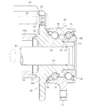
ブレーキロータ付き車輪軸受装置の実装状態でブレーキロータのパッド摺動面を切削加工するようにした従来の加工方法は、ブレーキロータ回転時におけるパッド摺動面の面振れを抑え、制動時に振動が発生することを防止することを目的とする加工法であるが、転動体を介して相対回転する外方部材と内方部材のうち、外方部材を固定した状態で内方部材に組み付けたブレーキロータのパッド摺動面を切削するものであり、切削荷重負荷時に転動体接触面の変形で軸受回転軸心と加工軸心にぶれが生じ、結果的にその分は面振れ精度が劣化する。図8を参照して説明するならば、外方部材2をチャックし、外方部材2のフランジ面4を基準面としてハブ輪6のフランジ面8を旋削する。このため、軸受自身の精度(アキシアル振れ、剛性等)が加工後のハブフランジ精度に影響を及ぼす。
The conventional machining method that cuts the pad sliding surface of the brake rotor while the wheel bearing device with the brake rotor is mounted suppresses the runout of the pad sliding surface during rotation of the brake rotor and generates vibration during braking. Brake rotor assembled to the inner member in a state in which the outer member is fixed out of the outer member and the inner member that rotate relative to each other through the rolling element. The pad sliding surface is cut, and the rolling contact surface is deformed by deformation of the rolling element contact surface when a cutting load is applied. As a result, the surface runout accuracy deteriorates accordingly. If it demonstrates with reference to FIG. 8, the
この発明の課題は、車輪軸受装置の車輪取付フランジのフランジ面を、軸受部分の精度(アキシアル振れ、剛性等)の影響を受けることなく切削加工することにある。 An object of the present invention is to cut the flange surface of a wheel mounting flange of a wheel bearing device without being affected by the accuracy (axial runout, rigidity, etc.) of the bearing portion.
この発明による車輪軸受装置は、外周に車体取付フランジを有し内周に2列の軌道を有する外方部材と、外周に車輪取付フランジを有するハブ輪とハブ輪の小径部に配置した内輪とからなる内方部材と、外方部材の軌道と内方部材の軌道との間に介在して両者を相対回転自在に支持する2列の転動体とを具備する車輪軸受装置の車輪取付フランジを切削加工する方法であって、車輪軸受装置を組み立てた状態で、外方部材のナックルパイロットをチャックしてハブ輪のホイールパイロット端面を旋削し、ハブ輪のホイールパイロット端面を基準としてハブ輪の車輪取付フランジのフランジ面を旋削することを特徴とするものである。 A wheel bearing device according to the present invention includes an outer member having a vehicle body mounting flange on the outer periphery and two rows of tracks on the inner periphery, a hub wheel having a wheel mounting flange on the outer periphery, and an inner ring disposed in a small diameter portion of the hub wheel, A wheel mounting flange of a wheel bearing device comprising: an inner member comprising: an inner member; and two rows of rolling elements that are interposed between a raceway of the outer member and a raceway of the inner member so as to be relatively rotatable. A method of cutting, in a state in which the wheel bearing device is assembled, chuck the knuckle pilot of the outer member to turn the wheel pilot end surface of the hub wheel, and the wheel of the hub wheel based on the wheel pilot end surface of the hub wheel The flange surface of the mounting flange is turned.
ハブ輪の車輪取付フランジのフランジ面を旋削する時のチャック位置としては、ハブ輪のホイールパイロット外径(請求項2)、ハブ輪おホイールパイロット内径(請求項3)が挙げられる。 Examples of the chuck position when turning the flange surface of the wheel mounting flange of the hub wheel include a wheel pilot outer diameter (Claim 2) and a hub wheel inner wheel pilot inner diameter (Claim 3 ) .
また、ハブ輪のホイールパイロット端面と外方部材の車体取付フランジのフランジ面とを挟むようにクランプするか(請求項4)、ハブ輪のホイールパイロット端面と外方部材のインボード側端面とを挟むようにクランプするようにしてもよい(請求項5)。 Further, the wheel pilot end surface of the hub wheel and the flange surface of the body mounting flange of the outer member are clamped so as to be sandwiched (Claim 4 ), or the wheel pilot end surface of the hub wheel and the inboard side end surface of the outer member are You may make it clamp so that it may pinch | interpose (Claim 5 ).
ハブ輪のホイールパイロット端面を基準としてハブ輪の車輪取付フランジのフランジ面を旋削することにより、外方部材を拘束することなく、ブレーキロータのパッド摺動面の面振れを抑えた高精度な加工が可能となる。具体例を挙げるならば、ハブ輪の車輪取付フランジのフランジ面の面振れを10μm以下とすることができる。 By turning the flange surface of the wheel mounting flange of the hub wheel on the basis of the wheel pilot end surface of the hub wheel, high-precision machining that suppresses the runout of the pad sliding surface of the brake rotor without restraining the outer member Is possible. If a specific example is given, the surface runout of the flange surface of the wheel mounting flange of the hub wheel can be set to 10 μm or less.
したがって、この発明によれば、ブレーキロータのパッド摺動面の回転振れを極めて小さくすることが可能であるため、実装状態でのブレーキロータの回転精度を改善し、制動時のブレーキジャダの発生を抑制することができる。 Therefore, according to the present invention, since the rotational runout of the pad sliding surface of the brake rotor can be made extremely small, the rotational accuracy of the brake rotor in the mounted state is improved and the brake judder is generated during braking. Can be suppressed.
まず、加工方法を説明する前に、その対象である車輪軸受装置について説明する。 First, before explaining a processing method, the wheel bearing device which is the object is explained.
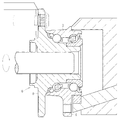
図1に示すように、この車輪軸受装置は、軸受外輪に相当する外方部材10と、軸受内輪に相当する内方部材20と、外方部材10と内方部材20との間に介在させた2列の転動体36を主要な構成要素としている。
As shown in FIG. 1, this wheel bearing device is interposed between an
外方部材10は、ナックル等の車体に固定するためのフランジすなわち車体取付フランジ12が外周に設けてあり、内周に二つの軌道14が形成してある。外方部材10の符号16で指してある部分は、ナックル等に形成した取り付け孔に挿入するパイロット部であって、ここではナックルパイロットと呼ぶこととする。
The
内方部材20はハブ輪20Aと内輪20Bとからなっている。ハブ輪20Aは、図1の左側に現れているアウトボード側の端部にホイールパイロット22が形成してあり、反対側のインボード側の端部に小径部24が形成してある。ハブ輪20Aの中心部には軸方向に貫通したセレーション(またはスプライン。以下同じ。)孔26が形成してある。ハブ輪20Aのアウトボード側端部の外周には、車輪を取り付けるためのフランジすなわち車輪取付フランジ28が設けてある。車輪取付フランジ28には複数のハブボルト30が取り付けてある。ハブ輪20Aの中間部外周には軌道32が形成してある。
The
内輪20Bはハブ輪20Aの小径部24にたとえば締りばめで配置してあり、小径部24から半径方向に立ち上がった面25に内輪20Bの端面を突き当ててある。この意味で面25を内輪突き当て面と呼ぶこととする。内輪20Bの外周には軌道34が形成してある。ハブ輪20Aの軌道32と内輪20Bの軌道34は外方部材10の二つの軌道14に対応する。そして、外方部材10の軌道14と内方部材20(ハブ輪20Aおよび内輪20B)の軌道32,34との間に2列の転動体36が転動自在に介在して、外方部材10と内方部材20を相対回転自在に支持する。
The
なお、外方部材10と内方部材20の対向面間における両端部にシール38が装着してある。シール38は軸受内部に異物が侵入するのを防止し、また、軸受内部に充填したグリースの漏洩を防止する。
Note that
上述の構成からなる車輪軸受装置においては、実車への組付けに際し、外方部材10の車体取付フランジ12をボルト締結によって車体に取り付ける。また、ハブ輪20Aのセレーション孔26に等速自在継手の外側継手部材に設けたセレーション軸を挿入し、そのセレーション軸の先端に形成したねじ軸にナットをねじ係合させて規格トルクで締め付け、ハブ輪20Aと内輪20Bを軸方向に加圧することにより、軸受に予圧を付与する。さらに、車輪取付フランジ28のハブボルト30にブレーキロータ(図示省略)と車輪のホイール(図示省略)を取り付け、ホイールナット(図示省略)を締め付ける。ホイールはホイールパイロット22によって、ブレーキロータはブレーキパイロット21によって、それぞれ心出しされる。
In the wheel bearing device having the above-described configuration, the vehicle
次に、上記車輪軸受装置における車輪取付フランジの加工方法を説明する。実施の形態の加工方法は第一工程と第二工程から成り立っている。第一工程では、車輪軸受を組み立てた状態でハブ輪20Aのホイールパイロット22の端面23を旋削する(図2)。第二工程では、ハブ輪20Aの車輪取付フランジ28のフランジ面29を旋削する(図1)。
Next, a method for processing the wheel mounting flange in the wheel bearing device will be described. The processing method according to the embodiment includes a first step and a second step. In the first step, the
第一工程は、図2を参照して説明するならば次のとおりである。車輪軸受装置の外方部材10のナックルパイロット16の外径をチャック装置42により保持する。そして、ハブ輪20Aのセレーション孔26にケレ46のセレーション軸を挿入し、ケレ46を矢印で示すように回転させることにより、ハブ輪20Aが車輪軸受装置の回転中心で回転するように回転力を与える。そして、白抜き矢印で示すようにバイト44に送りをかけ、ホイールパイロット22の端面23を旋削する。この加工により、各部材の寸法誤差や組立て誤差に拘らず、車輪軸受装置の回転時のフランジ面29の軸方向の振れは十分に小さくすることが可能となる。
If it demonstrates with reference to FIG. 2, a 1st process is as follows. The outer diameter of the
第二工程は、図1を参照して説明するならば次のとおりである。第一工程を終えた車輪軸受装置のハブ輪20Aにハブボルト30を取り付けた後、ブレーキロータを取り付け、ナットを締め付けて固定する。そうして構成した車輪軸受装置を、図1に示すように、ホイールパイロット22の外径にてチャック装置48aにより保持する。このとき、チャック装置48aをホイールパイロット22の端面23に突き当てる。この状態でセレーション孔26にケレ46のセレーション軸を挿入して内方部材20を回転させ、白抜き矢印で示すようにバイト50に送りをかけてハブ輪20Aの車輪取付フランジ28のフランジ麺29を旋削する。
If it demonstrates with reference to FIG. 1, a 2nd process is as follows. After the
この実施の形態によれば、第一工程で車輪軸受装置の回転に対する軸方向の面振れ精度を極めて小さくしたホイールパイロット22の端面23が確保でき、第二工程ではこれを基準としてハブ輪20Aの車輪取付フランジ28のフランジ面29を旋削することから、車輪軸受装置の回転に対するフランジ面29の軸方向の面振れを極めて小さくすることができる。このフランジ面29はブレーキロータを取り付ける面であることから、ブレーキロータのパッド摺動面の軸方向の面振れも極めて小さくすることができる。
According to this embodiment, it is possible to secure the
さらに、ブレーキロータを車輪取付フランジに固定する時に発生する歪も除去される。また、従来の技術(図8)では外方部材2を固定してハブ輪8のフランジ面を切削するため、切削荷重負荷がかかった場合に転動体接触面の変形で軸受回転軸心と加工軸心にぶれが生じ、結果的にその分は面振れ精度が劣化する現象が見られたが、この実施の形態では、ハブ輪20Aのフランジ面29を旋削する時は外方部材10は拘束されておらず、それゆえに軸受回転中心と加工軸心にぶれが生じにくく、それだけ高精度に加工することが可能である。
Further, distortion generated when the brake rotor is fixed to the wheel mounting flange is also eliminated. Further, in the prior art (FIG. 8), the
第二工程でハブ輪20Aのフランジ面29を旋削する時のハブ輪20Aのチャック位置は、図2を参照して上に述べたようにホイールパイロット22の外径のほか、図3ないし図5に示すような構成を採用することもできる。図3に示す変形例では、チャック装置48bによりハブ輪20Aのホイールパイロット22の内径をチャックしている。図4に示す変形例では、チャック装置48cによりハブ輪20Aのセレーション孔26の内径をチャックしている。図5に示す変形例では、チャック装置48dによりハブ輪20Aの車輪取付フランジ28の外径をチャックしている。この場合、チャック装置48aがホイールパイロット端面23と当接している。
The chuck position of the
また、図6および図7に示すように、ハブ輪20Aのホイールパイロット端面23と外方部材10を軸方向両側から挟み込むようにしてクランプするようにしてもよい。いずれも外方部材10の径方向移動を拘束しないので、軸受自身の精度(アキシアル振れ、剛性等)が加工後のハブ輪20Aのフランジ面29精度に影響を及ぼすといった不具合が解消する。図6の場合、一方の回転するチャック装置48aは、ハブ輪20Aのホイールパイロット22の外径を保持するとともに、ホイールパイロット22の端面23に当接している。他方の静止したチャック装置54aは、外方部材10の車体取付フランジ12のフランジ面13に当ててある。図7の場合、回転するチャック装置48aがハブ輪20Aのホイールパイロット22の外径を保持するとともに、ホイールパイロット22の端面23に当接しているのは図6と同様であるが、静止したチャック装置54bは外方部材10のインボード側端面18に当ててある。
As shown in FIGS. 6 and 7, the wheel pilot end face 23 of the
なお、車輪軸受装置としては、内方部材20(ハブ輪20A)にセレーション孔26が形成してある駆動輪用を例にとって説明したが、ハブ輪20Aが中実の非駆動輪用の車輪軸受装置であってもよい。この場合、たとえば、ハブ輪20Aのアウトボード側内径部にケレとなる爪を設ける。
The wheel bearing device has been described by way of example for a driving wheel in which the inner member 20 (
10 外方部材
12 車体取付フランジ
13 フランジ面
14 軌道
16 ナックルパイロット
18 インボード側端面
20 内方部材
20A ハブ輪
21 ブレーキパイロット
22 ホイールパイロット
23 端面
24 小径部
25 内輪突き当て面
26 セレーション孔
28 車輪取付フランジ
30 ハブボルト
32 軌道
20B 内輪
34 軌道
42 チャック装置
48a〜48c 回転するチャック装置
54a,54b 静止したチャック装置
44,50a,50b バイト
46 ケレ
DESCRIPTION OF
Claims (5)
車輪軸受装置を組み立てた状態で、外方部材のナックルパイロットをチャックしてハブ輪のホイールパイロット端面を旋削し、
ハブ輪のホイールパイロット端面を基準としてハブ輪の車輪取付フランジのフランジ面を旋削する、車輪軸受装置の加工方法。 An outer member having a vehicle body mounting flange on the outer periphery and two rows of tracks on the inner periphery, an inner member comprising a hub wheel having a wheel mounting flange on the outer periphery and an inner ring disposed on a small diameter portion of the hub wheel; A method of cutting a wheel mounting flange of a wheel bearing device comprising two rows of rolling elements that are interposed between a raceway of a side member and a raceway of an inner member so as to relatively rotatably support the both,
With the wheel bearing device assembled, chuck the knuckle pilot of the outer member and turn the wheel pilot end surface of the hub wheel,
A processing method for a wheel bearing device, wherein a flange surface of a wheel mounting flange of a hub wheel is turned on the basis of a wheel pilot end surface of the hub wheel.
Priority Applications (1)
| Application Number | Priority Date | Filing Date | Title |
|---|---|---|---|
| JP2005231094A JP4855005B2 (en) | 2005-08-09 | 2005-08-09 | Processing method of wheel bearing device |
Applications Claiming Priority (1)
| Application Number | Priority Date | Filing Date | Title |
|---|---|---|---|
| JP2005231094A JP4855005B2 (en) | 2005-08-09 | 2005-08-09 | Processing method of wheel bearing device |
Publications (2)
| Publication Number | Publication Date |
|---|---|
| JP2007045305A JP2007045305A (en) | 2007-02-22 |
| JP4855005B2 true JP4855005B2 (en) | 2012-01-18 |
Family
ID=37848507
Family Applications (1)
| Application Number | Title | Priority Date | Filing Date |
|---|---|---|---|
| JP2005231094A Active JP4855005B2 (en) | 2005-08-09 | 2005-08-09 | Processing method of wheel bearing device |
Country Status (1)
| Country | Link |
|---|---|
| JP (1) | JP4855005B2 (en) |
Cited By (2)
| Publication number | Priority date | Publication date | Assignee | Title |
|---|---|---|---|---|
| US8240249B2 (en) | 2007-02-23 | 2012-08-14 | Kabushiki Kaisha Sato | Ink roller cover device of portable type label printing applicator |
| CN105345560A (en) * | 2015-11-28 | 2016-02-24 | 余静远 | Turning tool of wheels of model racing car |
Families Citing this family (4)
| Publication number | Priority date | Publication date | Assignee | Title |
|---|---|---|---|---|
| JP4647333B2 (en) * | 2005-02-21 | 2011-03-09 | Ntn株式会社 | Cutting method of braking surface of wheel bearing device with brake rotor |
| JP6347973B2 (en) * | 2014-03-27 | 2018-06-27 | Ntn株式会社 | Wheel bearing device for driven wheel |
| CN105269004B (en) * | 2015-11-28 | 2017-07-28 | 余静远 | Model racing car wheel cutting tool |
| CN111959642B (en) * | 2020-07-10 | 2021-12-10 | 东风汽车底盘系统有限公司 | Method for assembling wheel assembly and whole vehicle axle |
Family Cites Families (3)
| Publication number | Priority date | Publication date | Assignee | Title |
|---|---|---|---|---|
| JP3973317B2 (en) * | 1999-04-22 | 2007-09-12 | Ntn株式会社 | Manufacturing method of wheel bearing device |
| JPH10217001A (en) * | 1997-02-04 | 1998-08-18 | Koyo Seiko Co Ltd | Machining method of shaft for hub unit |
| JP4581129B2 (en) * | 2005-08-09 | 2010-11-17 | Ntn株式会社 | Processing method of wheel bearing device with brake rotor |
-
2005
- 2005-08-09 JP JP2005231094A patent/JP4855005B2/en active Active
Cited By (3)
| Publication number | Priority date | Publication date | Assignee | Title |
|---|---|---|---|---|
| US8240249B2 (en) | 2007-02-23 | 2012-08-14 | Kabushiki Kaisha Sato | Ink roller cover device of portable type label printing applicator |
| CN105345560A (en) * | 2015-11-28 | 2016-02-24 | 余静远 | Turning tool of wheels of model racing car |
| CN105345560B (en) * | 2015-11-28 | 2017-06-30 | 余静远 | A kind of model racing car wheel cutting tool |
Also Published As
| Publication number | Publication date |
|---|---|
| JP2007045305A (en) | 2007-02-22 |
Similar Documents
| Publication | Publication Date | Title |
|---|---|---|
| US9839962B2 (en) | Processing method for brake rotor-equipped wheel bearing devices | |
| US20030098609A1 (en) | Bearing unit for wheel and manufacturing method thereof | |
| JP4855005B2 (en) | Processing method of wheel bearing device | |
| JP4543928B2 (en) | Manufacturing method of wheel bearing unit | |
| JP2000234624A (en) | Bearing unit for wheel and manufacture thereof | |
| JP2006138403A (en) | Wheel bearing device | |
| JP4994617B2 (en) | Processing method of wheel bearing device | |
| JP4360372B2 (en) | Manufacturing method of wheel bearing unit | |
| JP2002347402A (en) | Bearing unit for wheel and manufacturing method therefor | |
| JP4647333B2 (en) | Cutting method of braking surface of wheel bearing device with brake rotor | |
| JP4581129B2 (en) | Processing method of wheel bearing device with brake rotor | |
| JP4554467B2 (en) | Processing method of wheel bearing device with brake rotor | |
| JP4627017B2 (en) | Wheel bearing device | |
| JP2005306157A (en) | Rolling bearing unit for supporting vehicle wheel and method of manufacturing bearing units | |
| JP2007203949A (en) | Bearing device for wheel | |
| JP2002347406A (en) | Bearing unit for wheel and manufacturing method | |
| JP2007046636A (en) | Wheel bearing unit | |
| JP2002370104A (en) | Bearing unit for wheel and method of manufacturing the same | |
| JP2003214443A (en) | Bearing unit for wheel and method of manufacture | |
| JP2006021605A (en) | Rolling bearing unit for supporting wheel and its manufacturing method | |
| JP2007237332A (en) | Brake rotor machining method of bearing unit for drive wheel | |
| JP2007223364A (en) | Method of manufacturing bearing device for wheel | |
| JP2004225752A (en) | Manufacturing method for bearing unit for wheel | |
| JP2015205649A (en) | bearing unit | |
| JP2005331076A (en) | Wheel carrier unit |
Legal Events
| Date | Code | Title | Description |
|---|---|---|---|
| A621 | Written request for application examination |
Free format text: JAPANESE INTERMEDIATE CODE: A621 Effective date: 20080707 |
|
| RD04 | Notification of resignation of power of attorney |
Free format text: JAPANESE INTERMEDIATE CODE: A7424 Effective date: 20091106 |
|
| A977 | Report on retrieval |
Free format text: JAPANESE INTERMEDIATE CODE: A971007 Effective date: 20110228 |
|
| A131 | Notification of reasons for refusal |
Free format text: JAPANESE INTERMEDIATE CODE: A131 Effective date: 20110630 |
|
| A521 | Request for written amendment filed |
Free format text: JAPANESE INTERMEDIATE CODE: A523 Effective date: 20110829 |
|
| TRDD | Decision of grant or rejection written | ||
| A01 | Written decision to grant a patent or to grant a registration (utility model) |
Free format text: JAPANESE INTERMEDIATE CODE: A01 Effective date: 20111013 |
|
| A01 | Written decision to grant a patent or to grant a registration (utility model) |
Free format text: JAPANESE INTERMEDIATE CODE: A01 |
|
| A61 | First payment of annual fees (during grant procedure) |
Free format text: JAPANESE INTERMEDIATE CODE: A61 Effective date: 20111026 |
|
| FPAY | Renewal fee payment (event date is renewal date of database) |
Free format text: PAYMENT UNTIL: 20141104 Year of fee payment: 3 |
|
| R150 | Certificate of patent or registration of utility model |
Ref document number: 4855005 Country of ref document: JP Free format text: JAPANESE INTERMEDIATE CODE: R150 Free format text: JAPANESE INTERMEDIATE CODE: R150 |
|
| R250 | Receipt of annual fees |
Free format text: JAPANESE INTERMEDIATE CODE: R250 |
|
| R250 | Receipt of annual fees |
Free format text: JAPANESE INTERMEDIATE CODE: R250 |
|
| R250 | Receipt of annual fees |
Free format text: JAPANESE INTERMEDIATE CODE: R250 |
|
| R250 | Receipt of annual fees |
Free format text: JAPANESE INTERMEDIATE CODE: R250 |
|
| R250 | Receipt of annual fees |
Free format text: JAPANESE INTERMEDIATE CODE: R250 |
|
| R250 | Receipt of annual fees |
Free format text: JAPANESE INTERMEDIATE CODE: R250 |
|
| R250 | Receipt of annual fees |
Free format text: JAPANESE INTERMEDIATE CODE: R250 |
|
| R250 | Receipt of annual fees |
Free format text: JAPANESE INTERMEDIATE CODE: R250 |
|
| R250 | Receipt of annual fees |
Free format text: JAPANESE INTERMEDIATE CODE: R250 |
|
| R250 | Receipt of annual fees |
Free format text: JAPANESE INTERMEDIATE CODE: R250 |