JP4853877B2 - MANUFACTURING METHOD FOR CONNECTED SHEET PRODUCT, CONNECTING SHEET PRODUCT, AND METHOD FOR MANUFACTURING OPTICAL DISPLAY UNIT - Google Patents
MANUFACTURING METHOD FOR CONNECTED SHEET PRODUCT, CONNECTING SHEET PRODUCT, AND METHOD FOR MANUFACTURING OPTICAL DISPLAY UNIT Download PDFInfo
- Publication number
- JP4853877B2 JP4853877B2 JP2008284524A JP2008284524A JP4853877B2 JP 4853877 B2 JP4853877 B2 JP 4853877B2 JP 2008284524 A JP2008284524 A JP 2008284524A JP 2008284524 A JP2008284524 A JP 2008284524A JP 4853877 B2 JP4853877 B2 JP 4853877B2
- Authority
- JP
- Japan
- Prior art keywords
- sheet product
- release film
- film
- adhesive
- adhesive force
- Prior art date
- Legal status (The legal status is an assumption and is not a legal conclusion. Google has not performed a legal analysis and makes no representation as to the accuracy of the status listed.)
- Active
Links
Images


Classifications
-
- B—PERFORMING OPERATIONS; TRANSPORTING
- B29—WORKING OF PLASTICS; WORKING OF SUBSTANCES IN A PLASTIC STATE IN GENERAL
- B29C—SHAPING OR JOINING OF PLASTICS; SHAPING OF MATERIAL IN A PLASTIC STATE, NOT OTHERWISE PROVIDED FOR; AFTER-TREATMENT OF THE SHAPED PRODUCTS, e.g. REPAIRING
- B29C65/00—Joining or sealing of preformed parts, e.g. welding of plastics materials; Apparatus therefor
- B29C65/48—Joining or sealing of preformed parts, e.g. welding of plastics materials; Apparatus therefor using adhesives, i.e. using supplementary joining material; solvent bonding
- B29C65/50—Joining or sealing of preformed parts, e.g. welding of plastics materials; Apparatus therefor using adhesives, i.e. using supplementary joining material; solvent bonding using adhesive tape, e.g. thermoplastic tape; using threads or the like
- B29C65/5042—Joining or sealing of preformed parts, e.g. welding of plastics materials; Apparatus therefor using adhesives, i.e. using supplementary joining material; solvent bonding using adhesive tape, e.g. thermoplastic tape; using threads or the like covering both elements to be joined
-
- B—PERFORMING OPERATIONS; TRANSPORTING
- B29—WORKING OF PLASTICS; WORKING OF SUBSTANCES IN A PLASTIC STATE IN GENERAL
- B29C—SHAPING OR JOINING OF PLASTICS; SHAPING OF MATERIAL IN A PLASTIC STATE, NOT OTHERWISE PROVIDED FOR; AFTER-TREATMENT OF THE SHAPED PRODUCTS, e.g. REPAIRING
- B29C65/00—Joining or sealing of preformed parts, e.g. welding of plastics materials; Apparatus therefor
- B29C65/02—Joining or sealing of preformed parts, e.g. welding of plastics materials; Apparatus therefor by heating, with or without pressure
- B29C65/18—Joining or sealing of preformed parts, e.g. welding of plastics materials; Apparatus therefor by heating, with or without pressure using heated tools
-
- B—PERFORMING OPERATIONS; TRANSPORTING
- B29—WORKING OF PLASTICS; WORKING OF SUBSTANCES IN A PLASTIC STATE IN GENERAL
- B29C—SHAPING OR JOINING OF PLASTICS; SHAPING OF MATERIAL IN A PLASTIC STATE, NOT OTHERWISE PROVIDED FOR; AFTER-TREATMENT OF THE SHAPED PRODUCTS, e.g. REPAIRING
- B29C65/00—Joining or sealing of preformed parts, e.g. welding of plastics materials; Apparatus therefor
- B29C65/48—Joining or sealing of preformed parts, e.g. welding of plastics materials; Apparatus therefor using adhesives, i.e. using supplementary joining material; solvent bonding
- B29C65/4805—Joining or sealing of preformed parts, e.g. welding of plastics materials; Apparatus therefor using adhesives, i.e. using supplementary joining material; solvent bonding characterised by the type of adhesives
- B29C65/481—Non-reactive adhesives, e.g. physically hardening adhesives
- B29C65/4825—Pressure sensitive adhesives
-
- B—PERFORMING OPERATIONS; TRANSPORTING
- B29—WORKING OF PLASTICS; WORKING OF SUBSTANCES IN A PLASTIC STATE IN GENERAL
- B29C—SHAPING OR JOINING OF PLASTICS; SHAPING OF MATERIAL IN A PLASTIC STATE, NOT OTHERWISE PROVIDED FOR; AFTER-TREATMENT OF THE SHAPED PRODUCTS, e.g. REPAIRING
- B29C65/00—Joining or sealing of preformed parts, e.g. welding of plastics materials; Apparatus therefor
- B29C65/48—Joining or sealing of preformed parts, e.g. welding of plastics materials; Apparatus therefor using adhesives, i.e. using supplementary joining material; solvent bonding
- B29C65/50—Joining or sealing of preformed parts, e.g. welding of plastics materials; Apparatus therefor using adhesives, i.e. using supplementary joining material; solvent bonding using adhesive tape, e.g. thermoplastic tape; using threads or the like
- B29C65/5007—Joining or sealing of preformed parts, e.g. welding of plastics materials; Apparatus therefor using adhesives, i.e. using supplementary joining material; solvent bonding using adhesive tape, e.g. thermoplastic tape; using threads or the like characterised by the structure of said adhesive tape, threads or the like
- B29C65/5021—Joining or sealing of preformed parts, e.g. welding of plastics materials; Apparatus therefor using adhesives, i.e. using supplementary joining material; solvent bonding using adhesive tape, e.g. thermoplastic tape; using threads or the like characterised by the structure of said adhesive tape, threads or the like being multi-layered
-
- B—PERFORMING OPERATIONS; TRANSPORTING
- B29—WORKING OF PLASTICS; WORKING OF SUBSTANCES IN A PLASTIC STATE IN GENERAL
- B29C—SHAPING OR JOINING OF PLASTICS; SHAPING OF MATERIAL IN A PLASTIC STATE, NOT OTHERWISE PROVIDED FOR; AFTER-TREATMENT OF THE SHAPED PRODUCTS, e.g. REPAIRING
- B29C65/00—Joining or sealing of preformed parts, e.g. welding of plastics materials; Apparatus therefor
- B29C65/48—Joining or sealing of preformed parts, e.g. welding of plastics materials; Apparatus therefor using adhesives, i.e. using supplementary joining material; solvent bonding
- B29C65/50—Joining or sealing of preformed parts, e.g. welding of plastics materials; Apparatus therefor using adhesives, i.e. using supplementary joining material; solvent bonding using adhesive tape, e.g. thermoplastic tape; using threads or the like
- B29C65/5092—Joining or sealing of preformed parts, e.g. welding of plastics materials; Apparatus therefor using adhesives, i.e. using supplementary joining material; solvent bonding using adhesive tape, e.g. thermoplastic tape; using threads or the like characterised by the tape handling mechanisms, e.g. using vacuum
-
- B—PERFORMING OPERATIONS; TRANSPORTING
- B29—WORKING OF PLASTICS; WORKING OF SUBSTANCES IN A PLASTIC STATE IN GENERAL
- B29C—SHAPING OR JOINING OF PLASTICS; SHAPING OF MATERIAL IN A PLASTIC STATE, NOT OTHERWISE PROVIDED FOR; AFTER-TREATMENT OF THE SHAPED PRODUCTS, e.g. REPAIRING
- B29C66/00—General aspects of processes or apparatus for joining preformed parts
- B29C66/01—General aspects dealing with the joint area or with the area to be joined
- B29C66/05—Particular design of joint configurations
- B29C66/10—Particular design of joint configurations particular design of the joint cross-sections
- B29C66/11—Joint cross-sections comprising a single joint-segment, i.e. one of the parts to be joined comprising a single joint-segment in the joint cross-section
- B29C66/114—Single butt joints
- B29C66/1142—Single butt to butt joints
-
- B—PERFORMING OPERATIONS; TRANSPORTING
- B29—WORKING OF PLASTICS; WORKING OF SUBSTANCES IN A PLASTIC STATE IN GENERAL
- B29C—SHAPING OR JOINING OF PLASTICS; SHAPING OF MATERIAL IN A PLASTIC STATE, NOT OTHERWISE PROVIDED FOR; AFTER-TREATMENT OF THE SHAPED PRODUCTS, e.g. REPAIRING
- B29C66/00—General aspects of processes or apparatus for joining preformed parts
- B29C66/40—General aspects of joining substantially flat articles, e.g. plates, sheets or web-like materials; Making flat seams in tubular or hollow articles; Joining single elements to substantially flat surfaces
- B29C66/41—Joining substantially flat articles ; Making flat seams in tubular or hollow articles
- B29C66/43—Joining a relatively small portion of the surface of said articles
-
- B—PERFORMING OPERATIONS; TRANSPORTING
- B29—WORKING OF PLASTICS; WORKING OF SUBSTANCES IN A PLASTIC STATE IN GENERAL
- B29C—SHAPING OR JOINING OF PLASTICS; SHAPING OF MATERIAL IN A PLASTIC STATE, NOT OTHERWISE PROVIDED FOR; AFTER-TREATMENT OF THE SHAPED PRODUCTS, e.g. REPAIRING
- B29C66/00—General aspects of processes or apparatus for joining preformed parts
- B29C66/70—General aspects of processes or apparatus for joining preformed parts characterised by the composition, physical properties or the structure of the material of the parts to be joined; Joining with non-plastics material
- B29C66/72—General aspects of processes or apparatus for joining preformed parts characterised by the composition, physical properties or the structure of the material of the parts to be joined; Joining with non-plastics material characterised by the structure of the material of the parts to be joined
- B29C66/723—General aspects of processes or apparatus for joining preformed parts characterised by the composition, physical properties or the structure of the material of the parts to be joined; Joining with non-plastics material characterised by the structure of the material of the parts to be joined being multi-layered
-
- B—PERFORMING OPERATIONS; TRANSPORTING
- B29—WORKING OF PLASTICS; WORKING OF SUBSTANCES IN A PLASTIC STATE IN GENERAL
- B29C—SHAPING OR JOINING OF PLASTICS; SHAPING OF MATERIAL IN A PLASTIC STATE, NOT OTHERWISE PROVIDED FOR; AFTER-TREATMENT OF THE SHAPED PRODUCTS, e.g. REPAIRING
- B29C66/00—General aspects of processes or apparatus for joining preformed parts
- B29C66/80—General aspects of machine operations or constructions and parts thereof
- B29C66/83—General aspects of machine operations or constructions and parts thereof characterised by the movement of the joining or pressing tools
- B29C66/834—General aspects of machine operations or constructions and parts thereof characterised by the movement of the joining or pressing tools moving with the parts to be joined
- B29C66/8341—Roller, cylinder or drum types; Band or belt types; Ball types
- B29C66/83411—Roller, cylinder or drum types
- B29C66/83413—Roller, cylinder or drum types cooperating rollers, cylinders or drums
-
- G02B1/105—
-
- G—PHYSICS
- G02—OPTICS
- G02B—OPTICAL ELEMENTS, SYSTEMS OR APPARATUS
- G02B1/00—Optical elements characterised by the material of which they are made; Optical coatings for optical elements
- G02B1/10—Optical coatings produced by application to, or surface treatment of, optical elements
- G02B1/14—Protective coatings, e.g. hard coatings
-
- G—PHYSICS
- G02—OPTICS
- G02B—OPTICAL ELEMENTS, SYSTEMS OR APPARATUS
- G02B5/00—Optical elements other than lenses
- G02B5/30—Polarising elements
- G02B5/3025—Polarisers, i.e. arrangements capable of producing a definite output polarisation state from an unpolarised input state
- G02B5/3033—Polarisers, i.e. arrangements capable of producing a definite output polarisation state from an unpolarised input state in the form of a thin sheet or foil, e.g. Polaroid
-
- G—PHYSICS
- G02—OPTICS
- G02B—OPTICAL ELEMENTS, SYSTEMS OR APPARATUS
- G02B5/00—Optical elements other than lenses
- G02B5/30—Polarising elements
- G02B5/3083—Birefringent or phase retarding elements
-
- B—PERFORMING OPERATIONS; TRANSPORTING
- B29—WORKING OF PLASTICS; WORKING OF SUBSTANCES IN A PLASTIC STATE IN GENERAL
- B29C—SHAPING OR JOINING OF PLASTICS; SHAPING OF MATERIAL IN A PLASTIC STATE, NOT OTHERWISE PROVIDED FOR; AFTER-TREATMENT OF THE SHAPED PRODUCTS, e.g. REPAIRING
- B29C65/00—Joining or sealing of preformed parts, e.g. welding of plastics materials; Apparatus therefor
- B29C65/02—Joining or sealing of preformed parts, e.g. welding of plastics materials; Apparatus therefor by heating, with or without pressure
-
- B—PERFORMING OPERATIONS; TRANSPORTING
- B29—WORKING OF PLASTICS; WORKING OF SUBSTANCES IN A PLASTIC STATE IN GENERAL
- B29C—SHAPING OR JOINING OF PLASTICS; SHAPING OF MATERIAL IN A PLASTIC STATE, NOT OTHERWISE PROVIDED FOR; AFTER-TREATMENT OF THE SHAPED PRODUCTS, e.g. REPAIRING
- B29C65/00—Joining or sealing of preformed parts, e.g. welding of plastics materials; Apparatus therefor
- B29C65/48—Joining or sealing of preformed parts, e.g. welding of plastics materials; Apparatus therefor using adhesives, i.e. using supplementary joining material; solvent bonding
- B29C65/4805—Joining or sealing of preformed parts, e.g. welding of plastics materials; Apparatus therefor using adhesives, i.e. using supplementary joining material; solvent bonding characterised by the type of adhesives
- B29C65/483—Reactive adhesives, e.g. chemically curing adhesives
-
- B—PERFORMING OPERATIONS; TRANSPORTING
- B29—WORKING OF PLASTICS; WORKING OF SUBSTANCES IN A PLASTIC STATE IN GENERAL
- B29C—SHAPING OR JOINING OF PLASTICS; SHAPING OF MATERIAL IN A PLASTIC STATE, NOT OTHERWISE PROVIDED FOR; AFTER-TREATMENT OF THE SHAPED PRODUCTS, e.g. REPAIRING
- B29C65/00—Joining or sealing of preformed parts, e.g. welding of plastics materials; Apparatus therefor
- B29C65/48—Joining or sealing of preformed parts, e.g. welding of plastics materials; Apparatus therefor using adhesives, i.e. using supplementary joining material; solvent bonding
- B29C65/50—Joining or sealing of preformed parts, e.g. welding of plastics materials; Apparatus therefor using adhesives, i.e. using supplementary joining material; solvent bonding using adhesive tape, e.g. thermoplastic tape; using threads or the like
- B29C65/5007—Joining or sealing of preformed parts, e.g. welding of plastics materials; Apparatus therefor using adhesives, i.e. using supplementary joining material; solvent bonding using adhesive tape, e.g. thermoplastic tape; using threads or the like characterised by the structure of said adhesive tape, threads or the like
- B29C65/5028—Joining or sealing of preformed parts, e.g. welding of plastics materials; Apparatus therefor using adhesives, i.e. using supplementary joining material; solvent bonding using adhesive tape, e.g. thermoplastic tape; using threads or the like characterised by the structure of said adhesive tape, threads or the like being textile in woven or non-woven form
-
- B—PERFORMING OPERATIONS; TRANSPORTING
- B29—WORKING OF PLASTICS; WORKING OF SUBSTANCES IN A PLASTIC STATE IN GENERAL
- B29C—SHAPING OR JOINING OF PLASTICS; SHAPING OF MATERIAL IN A PLASTIC STATE, NOT OTHERWISE PROVIDED FOR; AFTER-TREATMENT OF THE SHAPED PRODUCTS, e.g. REPAIRING
- B29C66/00—General aspects of processes or apparatus for joining preformed parts
- B29C66/01—General aspects dealing with the joint area or with the area to be joined
- B29C66/05—Particular design of joint configurations
- B29C66/10—Particular design of joint configurations particular design of the joint cross-sections
- B29C66/11—Joint cross-sections comprising a single joint-segment, i.e. one of the parts to be joined comprising a single joint-segment in the joint cross-section
- B29C66/112—Single lapped joints
- B29C66/1122—Single lap to lap joints, i.e. overlap joints
-
- B—PERFORMING OPERATIONS; TRANSPORTING
- B29—WORKING OF PLASTICS; WORKING OF SUBSTANCES IN A PLASTIC STATE IN GENERAL
- B29C—SHAPING OR JOINING OF PLASTICS; SHAPING OF MATERIAL IN A PLASTIC STATE, NOT OTHERWISE PROVIDED FOR; AFTER-TREATMENT OF THE SHAPED PRODUCTS, e.g. REPAIRING
- B29C66/00—General aspects of processes or apparatus for joining preformed parts
- B29C66/70—General aspects of processes or apparatus for joining preformed parts characterised by the composition, physical properties or the structure of the material of the parts to be joined; Joining with non-plastics material
- B29C66/71—General aspects of processes or apparatus for joining preformed parts characterised by the composition, physical properties or the structure of the material of the parts to be joined; Joining with non-plastics material characterised by the composition of the plastics material of the parts to be joined
-
- B—PERFORMING OPERATIONS; TRANSPORTING
- B29—WORKING OF PLASTICS; WORKING OF SUBSTANCES IN A PLASTIC STATE IN GENERAL
- B29C—SHAPING OR JOINING OF PLASTICS; SHAPING OF MATERIAL IN A PLASTIC STATE, NOT OTHERWISE PROVIDED FOR; AFTER-TREATMENT OF THE SHAPED PRODUCTS, e.g. REPAIRING
- B29C66/00—General aspects of processes or apparatus for joining preformed parts
- B29C66/70—General aspects of processes or apparatus for joining preformed parts characterised by the composition, physical properties or the structure of the material of the parts to be joined; Joining with non-plastics material
- B29C66/72—General aspects of processes or apparatus for joining preformed parts characterised by the composition, physical properties or the structure of the material of the parts to be joined; Joining with non-plastics material characterised by the structure of the material of the parts to be joined
- B29C66/723—General aspects of processes or apparatus for joining preformed parts characterised by the composition, physical properties or the structure of the material of the parts to be joined; Joining with non-plastics material characterised by the structure of the material of the parts to be joined being multi-layered
- B29C66/7232—General aspects of processes or apparatus for joining preformed parts characterised by the composition, physical properties or the structure of the material of the parts to be joined; Joining with non-plastics material characterised by the structure of the material of the parts to be joined being multi-layered comprising a non-plastics layer
- B29C66/72321—General aspects of processes or apparatus for joining preformed parts characterised by the composition, physical properties or the structure of the material of the parts to be joined; Joining with non-plastics material characterised by the structure of the material of the parts to be joined being multi-layered comprising a non-plastics layer consisting of metals or their alloys
-
- B—PERFORMING OPERATIONS; TRANSPORTING
- B29—WORKING OF PLASTICS; WORKING OF SUBSTANCES IN A PLASTIC STATE IN GENERAL
- B29C—SHAPING OR JOINING OF PLASTICS; SHAPING OF MATERIAL IN A PLASTIC STATE, NOT OTHERWISE PROVIDED FOR; AFTER-TREATMENT OF THE SHAPED PRODUCTS, e.g. REPAIRING
- B29C66/00—General aspects of processes or apparatus for joining preformed parts
- B29C66/70—General aspects of processes or apparatus for joining preformed parts characterised by the composition, physical properties or the structure of the material of the parts to be joined; Joining with non-plastics material
- B29C66/72—General aspects of processes or apparatus for joining preformed parts characterised by the composition, physical properties or the structure of the material of the parts to be joined; Joining with non-plastics material characterised by the structure of the material of the parts to be joined
- B29C66/723—General aspects of processes or apparatus for joining preformed parts characterised by the composition, physical properties or the structure of the material of the parts to be joined; Joining with non-plastics material characterised by the structure of the material of the parts to be joined being multi-layered
- B29C66/7232—General aspects of processes or apparatus for joining preformed parts characterised by the composition, physical properties or the structure of the material of the parts to be joined; Joining with non-plastics material characterised by the structure of the material of the parts to be joined being multi-layered comprising a non-plastics layer
- B29C66/72327—General aspects of processes or apparatus for joining preformed parts characterised by the composition, physical properties or the structure of the material of the parts to be joined; Joining with non-plastics material characterised by the structure of the material of the parts to be joined being multi-layered comprising a non-plastics layer consisting of natural products or their composites, not provided for in B29C66/72321 - B29C66/72324
- B29C66/72328—Paper
-
- B—PERFORMING OPERATIONS; TRANSPORTING
- B29—WORKING OF PLASTICS; WORKING OF SUBSTANCES IN A PLASTIC STATE IN GENERAL
- B29C—SHAPING OR JOINING OF PLASTICS; SHAPING OF MATERIAL IN A PLASTIC STATE, NOT OTHERWISE PROVIDED FOR; AFTER-TREATMENT OF THE SHAPED PRODUCTS, e.g. REPAIRING
- B29C66/00—General aspects of processes or apparatus for joining preformed parts
- B29C66/70—General aspects of processes or apparatus for joining preformed parts characterised by the composition, physical properties or the structure of the material of the parts to be joined; Joining with non-plastics material
- B29C66/73—General aspects of processes or apparatus for joining preformed parts characterised by the composition, physical properties or the structure of the material of the parts to be joined; Joining with non-plastics material characterised by the intensive physical properties of the material of the parts to be joined, by the optical properties of the material of the parts to be joined, by the extensive physical properties of the parts to be joined, by the state of the material of the parts to be joined or by the material of the parts to be joined being a thermoplastic or a thermoset
- B29C66/739—General aspects of processes or apparatus for joining preformed parts characterised by the composition, physical properties or the structure of the material of the parts to be joined; Joining with non-plastics material characterised by the intensive physical properties of the material of the parts to be joined, by the optical properties of the material of the parts to be joined, by the extensive physical properties of the parts to be joined, by the state of the material of the parts to be joined or by the material of the parts to be joined being a thermoplastic or a thermoset characterised by the material of the parts to be joined being a thermoplastic or a thermoset
- B29C66/7392—General aspects of processes or apparatus for joining preformed parts characterised by the composition, physical properties or the structure of the material of the parts to be joined; Joining with non-plastics material characterised by the intensive physical properties of the material of the parts to be joined, by the optical properties of the material of the parts to be joined, by the extensive physical properties of the parts to be joined, by the state of the material of the parts to be joined or by the material of the parts to be joined being a thermoplastic or a thermoset characterised by the material of the parts to be joined being a thermoplastic or a thermoset characterised by the material of at least one of the parts being a thermoplastic
- B29C66/73921—General aspects of processes or apparatus for joining preformed parts characterised by the composition, physical properties or the structure of the material of the parts to be joined; Joining with non-plastics material characterised by the intensive physical properties of the material of the parts to be joined, by the optical properties of the material of the parts to be joined, by the extensive physical properties of the parts to be joined, by the state of the material of the parts to be joined or by the material of the parts to be joined being a thermoplastic or a thermoset characterised by the material of the parts to be joined being a thermoplastic or a thermoset characterised by the material of at least one of the parts being a thermoplastic characterised by the materials of both parts being thermoplastics
-
- B—PERFORMING OPERATIONS; TRANSPORTING
- B29—WORKING OF PLASTICS; WORKING OF SUBSTANCES IN A PLASTIC STATE IN GENERAL
- B29K—INDEXING SCHEME ASSOCIATED WITH SUBCLASSES B29B, B29C OR B29D, RELATING TO MOULDING MATERIALS OR TO MATERIALS FOR MOULDS, REINFORCEMENTS, FILLERS OR PREFORMED PARTS, e.g. INSERTS
- B29K2029/00—Use of polyvinylalcohols, polyvinylethers, polyvinylaldehydes, polyvinylketones or polyvinylketals or derivatives thereof as moulding material
-
- B—PERFORMING OPERATIONS; TRANSPORTING
- B29—WORKING OF PLASTICS; WORKING OF SUBSTANCES IN A PLASTIC STATE IN GENERAL
- B29K—INDEXING SCHEME ASSOCIATED WITH SUBCLASSES B29B, B29C OR B29D, RELATING TO MOULDING MATERIALS OR TO MATERIALS FOR MOULDS, REINFORCEMENTS, FILLERS OR PREFORMED PARTS, e.g. INSERTS
- B29K2105/00—Condition, form or state of moulded material or of the material to be shaped
- B29K2105/24—Condition, form or state of moulded material or of the material to be shaped crosslinked or vulcanised
-
- B—PERFORMING OPERATIONS; TRANSPORTING
- B29—WORKING OF PLASTICS; WORKING OF SUBSTANCES IN A PLASTIC STATE IN GENERAL
- B29K—INDEXING SCHEME ASSOCIATED WITH SUBCLASSES B29B, B29C OR B29D, RELATING TO MOULDING MATERIALS OR TO MATERIALS FOR MOULDS, REINFORCEMENTS, FILLERS OR PREFORMED PARTS, e.g. INSERTS
- B29K2995/00—Properties of moulding materials, reinforcements, fillers, preformed parts or moulds
- B29K2995/0018—Properties of moulding materials, reinforcements, fillers, preformed parts or moulds having particular optical properties, e.g. fluorescent or phosphorescent
- B29K2995/0034—Polarising
-
- B—PERFORMING OPERATIONS; TRANSPORTING
- B29—WORKING OF PLASTICS; WORKING OF SUBSTANCES IN A PLASTIC STATE IN GENERAL
- B29L—INDEXING SCHEME ASSOCIATED WITH SUBCLASS B29C, RELATING TO PARTICULAR ARTICLES
- B29L2009/00—Layered products
-
- G—PHYSICS
- G02—OPTICS
- G02F—OPTICAL DEVICES OR ARRANGEMENTS FOR THE CONTROL OF LIGHT BY MODIFICATION OF THE OPTICAL PROPERTIES OF THE MEDIA OF THE ELEMENTS INVOLVED THEREIN; NON-LINEAR OPTICS; FREQUENCY-CHANGING OF LIGHT; OPTICAL LOGIC ELEMENTS; OPTICAL ANALOGUE/DIGITAL CONVERTERS
- G02F1/00—Devices or arrangements for the control of the intensity, colour, phase, polarisation or direction of light arriving from an independent light source, e.g. switching, gating or modulating; Non-linear optics
- G02F1/01—Devices or arrangements for the control of the intensity, colour, phase, polarisation or direction of light arriving from an independent light source, e.g. switching, gating or modulating; Non-linear optics for the control of the intensity, phase, polarisation or colour
- G02F1/13—Devices or arrangements for the control of the intensity, colour, phase, polarisation or direction of light arriving from an independent light source, e.g. switching, gating or modulating; Non-linear optics for the control of the intensity, phase, polarisation or colour based on liquid crystals, e.g. single liquid crystal display cells
- G02F1/133—Constructional arrangements; Operation of liquid crystal cells; Circuit arrangements
- G02F1/1333—Constructional arrangements; Manufacturing methods
- G02F1/1335—Structural association of cells with optical devices, e.g. polarisers or reflectors
- G02F1/133528—Polarisers
-
- Y—GENERAL TAGGING OF NEW TECHNOLOGICAL DEVELOPMENTS; GENERAL TAGGING OF CROSS-SECTIONAL TECHNOLOGIES SPANNING OVER SEVERAL SECTIONS OF THE IPC; TECHNICAL SUBJECTS COVERED BY FORMER USPC CROSS-REFERENCE ART COLLECTIONS [XRACs] AND DIGESTS
- Y10—TECHNICAL SUBJECTS COVERED BY FORMER USPC
- Y10T—TECHNICAL SUBJECTS COVERED BY FORMER US CLASSIFICATION
- Y10T156/00—Adhesive bonding and miscellaneous chemical manufacture
- Y10T156/10—Methods of surface bonding and/or assembly therefor
- Y10T156/1052—Methods of surface bonding and/or assembly therefor with cutting, punching, tearing or severing
- Y10T156/1062—Prior to assembly
- Y10T156/1064—Partial cutting [e.g., grooving or incising]
-
- Y—GENERAL TAGGING OF NEW TECHNOLOGICAL DEVELOPMENTS; GENERAL TAGGING OF CROSS-SECTIONAL TECHNOLOGIES SPANNING OVER SEVERAL SECTIONS OF THE IPC; TECHNICAL SUBJECTS COVERED BY FORMER USPC CROSS-REFERENCE ART COLLECTIONS [XRACs] AND DIGESTS
- Y10—TECHNICAL SUBJECTS COVERED BY FORMER USPC
- Y10T—TECHNICAL SUBJECTS COVERED BY FORMER US CLASSIFICATION
- Y10T156/00—Adhesive bonding and miscellaneous chemical manufacture
- Y10T156/10—Methods of surface bonding and/or assembly therefor
- Y10T156/1052—Methods of surface bonding and/or assembly therefor with cutting, punching, tearing or severing
- Y10T156/1062—Prior to assembly
- Y10T156/1075—Prior to assembly of plural laminae from single stock and assembling to each other or to additional lamina
-
- Y—GENERAL TAGGING OF NEW TECHNOLOGICAL DEVELOPMENTS; GENERAL TAGGING OF CROSS-SECTIONAL TECHNOLOGIES SPANNING OVER SEVERAL SECTIONS OF THE IPC; TECHNICAL SUBJECTS COVERED BY FORMER USPC CROSS-REFERENCE ART COLLECTIONS [XRACs] AND DIGESTS
- Y10—TECHNICAL SUBJECTS COVERED BY FORMER USPC
- Y10T—TECHNICAL SUBJECTS COVERED BY FORMER US CLASSIFICATION
- Y10T156/00—Adhesive bonding and miscellaneous chemical manufacture
- Y10T156/10—Methods of surface bonding and/or assembly therefor
- Y10T156/1052—Methods of surface bonding and/or assembly therefor with cutting, punching, tearing or severing
- Y10T156/1082—Partial cutting bonded sandwich [e.g., grooving or incising]
-
- Y—GENERAL TAGGING OF NEW TECHNOLOGICAL DEVELOPMENTS; GENERAL TAGGING OF CROSS-SECTIONAL TECHNOLOGIES SPANNING OVER SEVERAL SECTIONS OF THE IPC; TECHNICAL SUBJECTS COVERED BY FORMER USPC CROSS-REFERENCE ART COLLECTIONS [XRACs] AND DIGESTS
- Y10—TECHNICAL SUBJECTS COVERED BY FORMER USPC
- Y10T—TECHNICAL SUBJECTS COVERED BY FORMER US CLASSIFICATION
- Y10T428/00—Stock material or miscellaneous articles
- Y10T428/14—Layer or component removable to expose adhesive
- Y10T428/1476—Release layer
Description
本発明は、シート製品同士のそれぞれの端面同士を連結する連結シート製品の製造方法、連結シート製品、および、この連結シート製品を用いて製造可能な光学表示ユニットの製造方法に関する。 The present invention relates to a manufacturing method of a connecting sheet product that connects end surfaces of sheet products, a connecting sheet product, and a manufacturing method of an optical display unit that can be manufactured using the connecting sheet product.
光学フィルムを光学表示ユニット(例えば、液晶セルが封入されたガラス基板ユニット等)に貼り合わせる製造方法について以下に説明する。まず、光学フィルム部材を有する長尺のシート製品をロール原反として製造する。この「長尺のシート製品」として、例えば、液晶表示装置に用いられる偏光板原反等がある。例えば、偏光板のロール原反は、以下の製造工程で製造される。前工程として、(A)偏光子を得る工程。(B)偏光板を製造する工程。ここでは、偏光子の両面あるいは片面に接着剤を介して偏光子保護フィルムを積層し、乾燥させて、偏光板を製造する。(C)離型フィルム(セパレータとも称される)及び表面保護フィルムを貼り合わせる工程。以上の前工程では、長尺のシート製品が製造され、ロール状に巻き取られ、後工程に提供される。 A manufacturing method for bonding an optical film to an optical display unit (for example, a glass substrate unit in which a liquid crystal cell is sealed) will be described below. First, a long sheet product having an optical film member is manufactured as a raw roll. As this “long sheet product”, there is, for example, a polarizing plate raw material used in a liquid crystal display device. For example, the roll of the polarizing plate is manufactured by the following manufacturing process. As a previous step, (A) a step of obtaining a polarizer. (B) The process of manufacturing a polarizing plate. Here, a polarizer protective film is laminated on both sides or one side of the polarizer via an adhesive and dried to produce a polarizing plate. (C) A step of bonding a release film (also referred to as a separator) and a surface protective film. In the above pre-process, a long sheet product is manufactured, wound into a roll, and provided to the post-process.
(D)ロール原反のスリット工程。ロール原反が幅広であるため、最終製品である光学表示ユニットのサイズに合わせて所定サイズにロール原反をスリットする。以上のとおり長尺のシート製品はロール原反として形成される。得られたロール原反から長尺の偏光板を引き出して加工する場合、連続的にロール供給するために、ロール原反の残長が少なくなると、次のロールと継ぎ合わせて送り込む方法がとられる。この継ぎ合わせ方法(スプライス方法と称されることがある)としては、従来から、図7(a)、(b)に示すように、一方シート製品701の端部分と他方シート製品702の端部分を重ね合わせて、溶着する方法や、接着テープで接着する方法があった。なお、図7は、シート製品同士の連結部分の断面図である。
(D) A slit process of the roll. Since the roll material is wide, the roll material is slit to a predetermined size in accordance with the size of the optical display unit as the final product. As described above, a long sheet product is formed as a raw roll. When a long polarizing plate is drawn out from the obtained roll raw material and processed, in order to continuously supply the roll, when the remaining length of the roll raw material decreases, a method of feeding the next roll together is used. . As a joining method (sometimes referred to as a splicing method), as shown in FIGS. 7A and 7B, an end portion of one
また、シート製品のロール原反を連続的に繰り出し、セパレータのみを剥離して偏光板の欠点を自動検査する場合に、ロール原反ごとに中断して行なうと、作業効率が低下する。そこで、現在検査中のシート製品の端部と次のシート製品の端部を継ぎ合わせて行なうことが提案されている。しかしながら、上記のようにシート製品の端部分同士を重ね合わせて継ぎ合わせた場合、セパレータのみを剥離することができない。 In addition, when the roll raw material of the sheet product is continuously fed out and only the separator is peeled off to automatically inspect the defects of the polarizing plate, if it is interrupted for each roll raw material, the working efficiency is lowered. Therefore, it has been proposed that the end of the sheet product currently being inspected is joined to the end of the next sheet product. However, when the end portions of the sheet product are overlapped and joined together as described above, only the separator cannot be peeled off.
次いで、光学表示ユニットを構成する部材の基板に光学部材を有するシート製品を貼り合わせる工程について説明する。例えば、特許文献1(特開2007−140046)では、帯状のシート製品が巻き取られたロールからシート製品を引き出して供給し、シート製品の欠陥を検出し、この検出結果に基づいてシート製品を切断して個々のシート製品に加工し、個々に切断加工されたシート製品を基板に貼り合わせる構成が記載されている。この貼り合わせに際し、シート製品からセパレータのみが剥離され、剥離された後に残存する粘着剤を介して基板に貼り合わされる構成である。 Next, a process of bonding a sheet product having an optical member to a substrate of a member constituting the optical display unit will be described. For example, in Patent Document 1 (Japanese Patent Application Laid-Open No. 2007-140046), a sheet product is pulled out and supplied from a roll on which a strip-shaped sheet product is wound, a defect of the sheet product is detected, and a sheet product is detected based on the detection result. A configuration is described in which the sheet product is cut and processed into individual sheet products, and the individually cut sheet products are bonded to a substrate. At the time of this bonding, only the separator is peeled from the sheet product, and is bonded to the substrate through the adhesive remaining after the peeling.
これに対し、セパレータは切断せずに連続性を維持させつつ、他の部材(偏光板、表面保護フィルム)を切断し、セパレータのみを剥離しながら、残存する粘着剤を介してシート製品を基板に貼り合わせる方法が提案されている。さらに、連続して貼り合わせ処理ができるように、上述したように、現に供給されているシート製品と次のシート製品とを継ぎ合わせることが必要となる。この場合も上述と同様に、シート製品の端部分同士を重ね合わせて継ぎ合わせた場合、セパレータのみを剥離することができない。 On the other hand, while maintaining the continuity without cutting the separator, other members (polarizing plate, surface protective film) are cut, and only the separator is peeled off, and the sheet product is substrated through the remaining adhesive. There has been proposed a method of pasting together. Further, as described above, it is necessary to join the sheet product currently supplied and the next sheet product so that the bonding process can be continuously performed. In this case as well, when the end portions of the sheet product are overlapped and joined together, only the separator cannot be peeled off.
本発明は、上記の実情に鑑みてなされたものであって、その目的は、2つあるいはそれ以上のシート製品のそれぞれの端面同士を対向させて連結することが可能な連結シート製品の製造方法、連結シート製品および光学表示ユニットの製造方法を提供することにある。 The present invention has been made in view of the above-described circumstances, and the object thereof is a method for manufacturing a connected sheet product capable of connecting the end surfaces of two or more sheet products facing each other. Another object of the present invention is to provide a method for manufacturing a connecting sheet product and an optical display unit.
本発明は、長尺の第1シート製品のロール原反から先行して送り出される第1シート製品の後端と、次の長尺の第2シート製品のロール原反から送りだされる第2シート製品の先端とを順次連結して連続した連結シート製品を製造する連結シート製品の製造方法であって、
該第1シート製品は、第1表面保護フィルムと第1光学部材と第1粘着剤層と第1離型フィルムとをこの順に有し、該第2シート製品は、第2表面保護フィルムと第2光学部材と第2粘着剤層と第2離型フィルムとをこの順に有し、
第1シート製品の幅方向端面と、第2シート製品の幅方向端面と対向させ、第1離型フィルムと第2離型フィルムとを第1連結部材により連結し、第1表面保護フィルムと第2表面保護フィルムとを第2連結部材により連結し、
第1連結部材と第2離型フィルムとの接着力をA、第2離型フィルムと第2粘着剤層との接着力をB、第2連結部材と第2表面保護フィルムとの接着力をCとしたとき、C≧A>Bの関係を満足し、かつ前記接着力Aおよび前記接着力Cが、前記接着力Bより10倍以上大きいことを特徴とする。
The present invention provides a rear end of the first sheet product that is fed out in advance from the roll material of the long first sheet product, and a second material that is fed out from the roll material of the next long second sheet product. A method for manufacturing a connected sheet product, in which a front end of a sheet product is sequentially connected to manufacture a continuous connected sheet product,
The first sheet product includes a first surface protection film, a first optical member, a first pressure-sensitive adhesive layer, and a first release film in this order, and the second sheet product includes a second surface protection film and a first release film. 2 optical members, a second pressure-sensitive adhesive layer, and a second release film in this order,
The width direction end face of the first sheet product and the width direction end face of the second sheet product are opposed to each other, the first release film and the second release film are connected by the first connecting member, and the first surface protection film and the first 2 Connect the surface protective film with the second connecting member,
The adhesive force between the first connecting member and the second release film is A, the adhesive force between the second release film and the second pressure-sensitive adhesive layer is B, and the adhesive force between the second connecting member and the second surface protective film is When C, the relationship C ≧ A> B is satisfied , and the adhesive force A and the adhesive force C are 10 times or more larger than the adhesive force B.
この構成の作用効果は以下のとおりである。シート製品は、光学部材と、当該光学部材の一方面側に粘着剤を介して設けられる離型フィルムとを少なくとも有する。光学部材は、特に制限されず、例えば、各種光学フィルムの単層構成、積層構成が挙げられる。光学部材の厚みは、その構成によって異なるが、例えば、5μmから500μmの範囲が挙げられる。光学フィルムとしては、例えば、偏光板、位相差板、輝度向上フィルム、光拡散板等が挙げられる。光学部材は、光学フィルム以外に各種フィルムが積層されて構成されてもよい。この各種フィルムとしては、例えば、偏光子を保護する目的の偏光子保護フィルム、最外層表面に設けられる表面保護部材または離型フィルム等が挙げられる。表面保護部材は、フィルムで構成されているのが好ましい。光学部材が積層構成の場合、それぞれの層は、例えば接着剤、粘着剤等を介して設けられる。また、共押出し製造手法によって形成された積層フィルムを部材として用いて光学部材を構成することができる。光学部材は、好ましくは偏光板、又は偏光板を含む積層構成である。偏光板は、例えば、延伸、染色されたポリビニルアルコールフィルムの偏光子を有し、その偏光子の少なくとも一方面側に、例えばトリアセチルセルロースフィルムの偏光子保護フィルムが接着剤を介して設けられる構成がある。 The effects of this configuration are as follows. The sheet product has at least an optical member and a release film provided on one surface side of the optical member via an adhesive. An optical member in particular is not restrict | limited, For example, the single layer structure and laminated structure of various optical films are mentioned. Although the thickness of an optical member changes with the structures, for example, the range of 5 micrometers-500 micrometers is mentioned. Examples of the optical film include a polarizing plate, a retardation plate, a brightness enhancement film, a light diffusion plate, and the like. The optical member may be configured by laminating various films in addition to the optical film. Examples of the various films include a polarizer protective film for protecting the polarizer, a surface protective member provided on the outermost layer surface, a release film, and the like. The surface protection member is preferably made of a film. When the optical member has a laminated configuration, each layer is provided via, for example, an adhesive or a pressure-sensitive adhesive. Moreover, an optical member can be comprised using the laminated | multilayer film formed by the coextrusion manufacturing method as a member. The optical member is preferably a polarizing plate or a laminated structure including a polarizing plate. A polarizing plate has, for example, a polarizer of a stretched and dyed polyvinyl alcohol film, and a polarizer protective film of, for example, a triacetyl cellulose film is provided on at least one surface side of the polarizer via an adhesive. There is.
粘着剤は、例えば、ゴム系粘着剤、アクリル系粘着剤、シリコーン系粘着剤、エポキシ系粘着剤またはセルロース系粘着剤等が挙げられる。耐熱性や透明性に優れるアクリル系粘着剤が好ましい。粘着剤は、層として形成されることが好ましく、この場合の層厚みは、例えば、1〜50μmの範囲が挙げられる。 Examples of the adhesive include a rubber adhesive, an acrylic adhesive, a silicone adhesive, an epoxy adhesive, and a cellulose adhesive. An acrylic pressure-sensitive adhesive having excellent heat resistance and transparency is preferred. The pressure-sensitive adhesive is preferably formed as a layer, and the layer thickness in this case is, for example, in the range of 1 to 50 μm.
アクリル系粘着剤は、通常、粘着性を与える主モノマー、凝集性を与えるコモノマー、粘着性を与えつつ架橋点となる官能性含有モノマーを重合させて得られる。このアクリル系粘着剤のガラス転移温度は、好ましくは−60℃〜−10℃であり、重量平均分子量は、好ましくは20万〜200万の範囲であり、屈折率は、好ましくは1.45〜1.65である。以上の条件によって、液晶セルに長時間貼着するために実用上十分な接着力が得られる。なお、上記特性のアクリル系粘着剤は、例えば、大日本図書株式会社発行 中野勝彦著「接着・粘着の化学と応用」を参考に製造できる。 The acrylic pressure-sensitive adhesive is usually obtained by polymerizing a main monomer that imparts tackiness, a comonomer that imparts cohesiveness, and a functional-containing monomer that serves as a crosslinking point while imparting tackiness. The glass transition temperature of this acrylic pressure-sensitive adhesive is preferably −60 ° C. to −10 ° C., the weight average molecular weight is preferably in the range of 200,000 to 2 million, and the refractive index is preferably 1.45 to 1.45. 1.65. Under the above conditions, a practically sufficient adhesive force can be obtained for adhering to the liquid crystal cell for a long time. The acrylic pressure-sensitive adhesive having the above characteristics can be produced, for example, with reference to “Adhesion / Tackiness Chemistry and Application” by Katsuhiko Nakano published by Dainippon Tosho.
離型フィルムの材料および厚みは、特に制限されず、各種フィルムを使用できる。例えば、ポリエチレンテレフタレート(PET)フィルム、ポリエチレン(PE)フィルム、ポリプロピレン(PP)フィルム等が使用でき、フィルム厚みは、例えば、12μm〜80μmの範囲が挙げられる。 The material and thickness of the release film are not particularly limited, and various films can be used. For example, a polyethylene terephthalate (PET) film, a polyethylene (PE) film, a polypropylene (PP) film, etc. can be used, and the film thickness is, for example, in the range of 12 μm to 80 μm.
連結シート製品を構成するシート製品は、2つのシート製品に制限されず、複数のシート製品が直列に連結される構成も例示される。また、連結シート製品を構成する第1のシート製品と、当該第1シート製品に連結される第2シート製品のそれぞれの長尺方向長さが同一でもよく、異なっていてもよい。本発明において、シート製品の「長尺方向の長さ」は、それと直交する幅方向長さの10倍以上であることが好ましい。連結される複数のシート製品は、それぞれが、同一の部材要素で構成されていてもよく、異なる部材要素で構成されていてもよい。 The sheet product constituting the connection sheet product is not limited to two sheet products, and a configuration in which a plurality of sheet products are connected in series is also exemplified. Further, the lengths in the longitudinal direction of the first sheet product constituting the connection sheet product and the second sheet product connected to the first sheet product may be the same or different. In the present invention, the “length in the longitudinal direction” of the sheet product is preferably at least 10 times the length in the width direction perpendicular thereto. Each of the plurality of sheet products to be connected may be composed of the same member element or may be composed of different member elements.
連結方法は、第1シート製品の幅方向端面と、第2シート製品の幅方向端面とを対向させ、当該第1、第2シート製品のそれぞれの離型フィルム同士と、当該離型フィルムと反対表面のそれぞれのシート製品表面部材同士とを、連結部材を用いてそれぞれ連結する方法である。本発明において「対向」は、シート製品の端面同士を、例えば0.1mm〜20mmの隙間を有して、あるいは隙間なく配置し、シート製品同士の重なりがないことを意味する。第1、第2シート製品の端面同士を対向させる場合に、それぞれの端面ラインが平行であることが好ましい。そのため、連結の前に、第1、第2シート製品の端面部分は、シート製品の幅方向に平行に切断されてもよい。 In the connection method, the width direction end surface of the first sheet product and the width direction end surface of the second sheet product are opposed to each other, and the release films of the first and second sheet products are opposite to each other. It is a method of connecting the respective sheet product surface members on the surface using connecting members. In the present invention, “opposite” means that the end surfaces of the sheet products are arranged with a gap of, for example, 0.1 mm to 20 mm or without a gap, and the sheet products do not overlap each other. When the end surfaces of the first and second sheet products are opposed to each other, it is preferable that the end surface lines are parallel to each other. Therefore, the end surface portions of the first and second sheet products may be cut in parallel to the width direction of the sheet product before the connection.
第1、第2シート製品のそれぞれの離型フィルム同士が連結部材を用いて連結される。これら離型フィルムと反対表面のそれぞれのシート製品表面部材同士が、連結部材を用いて連結される。シート製品表面部材は、上述の光学部材中の最表面部材であり、例えば、表面保護部材、偏光子保護フィルム等が挙げられる。 The release films of the first and second sheet products are connected to each other using a connecting member. The sheet product surface members opposite to the release film are connected to each other using a connecting member. The sheet product surface member is the outermost surface member in the above-described optical member, and examples thereof include a surface protection member and a polarizer protective film.
連結部材は、例えば、接着テープ等が挙げられる。また、連結方法として、例えば、第1シート製品と第2シート製品の端面同士を対向させ、対向させた部分のシート表面を熱溶着用のコテで直接押さえ、この部分のシート表面を熱溶着させて連結する方法がある。この場合、溶融して固化したシート表面部材が連結部材に相当する(図3参照)。また、連結に際し、同一の連結部材を用いることが好ましく、それが、接着テープであることがより好ましい。接着テープは、手作業でも短時間に連結作業を行えるからである。連結部材は、シート製品の幅方向全長に設けられることが好ましい。 As for a connection member, an adhesive tape etc. are mentioned, for example. Further, as a connecting method, for example, the end surfaces of the first sheet product and the second sheet product are opposed to each other, and the opposed sheet surface is directly pressed with a hot welding iron, and the sheet surface of this part is thermally welded. There is a way to connect. In this case, the sheet surface member melted and solidified corresponds to the connecting member (see FIG. 3). Moreover, it is preferable to use the same connection member in the case of connection, and it is more preferable that it is an adhesive tape. This is because the adhesive tape can be connected manually in a short time. The connecting member is preferably provided over the entire length in the width direction of the sheet product.
接着テープは、例えば、不織布に感圧性粘着剤を含浸させたものや、ポリプロピレンなどの基材に感圧性粘着剤が塗布されたものが挙げられる。この接着テープの厚みが10μmから5mmの範囲のものが好ましく、接着力が1N/25mm〜30N/25mmであるものが好ましい。接着力の試験方法は、JIS Z 0237(1991)の180度引き剥がし法に準ずる。この場合、試験板(被着体)は、シート製品の構成による。さらに、接着テープの引張り強度が100N/25mm以上であって、伸び率が200%以下であるものが好ましい。引張り強度の試験方法は、JIS Z 0237(1991)に準ずる。以上のような条件の接着テープであれば、シート製品同士を連結する加工作業を連続的に行っても、接着テープが破断する心配がない。 Examples of the adhesive tape include those obtained by impregnating a non-woven fabric with a pressure-sensitive adhesive, and those obtained by applying a pressure-sensitive adhesive to a base material such as polypropylene. The adhesive tape preferably has a thickness in the range of 10 μm to 5 mm, and preferably has an adhesive strength of 1 N / 25 mm to 30 N / 25 mm. The adhesive strength test method is in accordance with the 180 degree peeling method of JIS Z 0237 (1991). In this case, the test plate (the adherend) depends on the configuration of the sheet product. Further, it is preferable that the adhesive tape has a tensile strength of 100 N / 25 mm or more and an elongation of 200% or less. The tensile strength test method is in accordance with JIS Z 0237 (1991). If it is an adhesive tape of the above conditions, there will be no fear that an adhesive tape will be fractured, even if the processing operation which connects sheet products is performed continuously.
連結作業は、手作業で行うことができるが、例えば貼着用ロール等の専用機器を用いて行うこともできる。貼着用ロールとして、ロール芯に厚さ数ミリから数十ミリ程度のゴム層を被覆した構成のものが例示できる。 The connection work can be performed manually, but can also be performed using a dedicated device such as a sticking roll. As a sticking roll, the thing of the structure which coat | covered the rubber layer about several millimeters to several tens of millimeters in thickness to a roll core can be illustrated.
連結作業に際し、第1、第2シート製品のそれぞれの離型フィルム同士の連結作業と、離型フィルムと反対表面のそれぞれのシート製品表面部材同士の連結作業は、どのような順番で行うこともでき、また並行して行うこともできる。 In the connection work, the connection work between the release films of the first and second sheet products and the connection work between the sheet product surface members on the surface opposite to the release film may be performed in any order. Can be done in parallel.
以上の製造方法で得られた連結シート製品は、例えば、製造ラインを停止することなく、シート製品を連続加工することができるため生産性に優れる。さらに、連結シート製品の構成によれば、粘着剤上に設けられた離型フィルムを、他の構成部材と干渉することなく滑らかに剥離させることができる。そして、この離型フィルムの剥離の際に、それぞれのシート製品表面部材同士を連結する連結部材によって、第1シート製品と第2シート製品の連結は維持される。このため、離型フィルムが剥離されたシート製品を、粘着剤を介して所望の被貼着体に貼着する場合に、連続作業が維持でき、連続生産上のトラブルが大幅に低減される。 The connected sheet product obtained by the above manufacturing method is excellent in productivity because, for example, the sheet product can be continuously processed without stopping the production line. Furthermore, according to the structure of a connection sheet product, the release film provided on the adhesive can be smoothly peeled without interfering with other constituent members. And at the time of peeling of this release film, the connection of a 1st sheet product and a 2nd sheet product is maintained by the connection member which connects each sheet | seat product surface member. For this reason, when sticking the sheet product from which the release film has been peeled off to a desired adherend via an adhesive, continuous work can be maintained, and troubles in continuous production are greatly reduced.
離型フィルムが連続して滑らかに剥離でき、かつ連結部分での切れが生じないためには、以下の点が要求される。図2に示す剥離方向で、離型フィルム12、22が剥離される場合において、連結部材30bと第2シート製品2の離型フィルム22との接着力をA(楕円aの部分)、第2シート製品2の離型フィルム22と粘着剤層22aとの接着力をB(楕円bの部分)、連結部材30aと第2シート製品2の表面保護フィルム23との接着力をC(楕円cの部分)とした場合に、以下の関係が成り立つ。
(数式1)
C≧A>B
The following points are required in order for the release film to be continuously and smoothly peeled off and not to be cut at the connecting portion. When the
(Formula 1)
C ≧ A> B
接着力は、上記の接着力の試験方法で測定できる。上記の接着力A及びCは、好ましくは、接着力Bに対して10倍以上大きい。幅寸法が1300mm以上のシート製品を連結する場合には、上記接着力A及びCは、好ましくは、接着力Bに対して100倍以上(例えば100倍〜300倍)である。上記接着力A、B、Cは、まず、シート製品の構成によって、接着力Bが決定されるので、連結部材を適宜変更して、接着力A及びCを適宜決定することができる。例えば、シート製品がポリエチレンテレフタレートフィルムからなる表面保護フィルム、アクリル系粘着剤、偏光板、アクリル系粘着剤、シリコーン処理されたポリエチレンテレフタレートフィルムからなる離型フィルムの積層構成の場合、上記アクリル系粘着剤層に対するシリコーン処理されたポリエチレンテレフタレートフィルムの接着力(剥離力)Bは、通常、0.005N/25mm〜0.1N/25mmとなる。この場合、連結部材としては、上記離型フィルムに対する接着力A及び上記表面保護フィルムに対する接着力Cが、上記接着力Bの10倍以上となるものを用いることが好ましい。また、粘着剤層22aと偏光板21との接着力、偏光板22と表面保護フィルム23と粘着剤層23aを介しての接着力が、連結部材30bと第2シート製品2の離型フィルム22との接着力A以上であることが必要である。
The adhesive strength can be measured by the above-described adhesive strength test method. The adhesive forces A and C are preferably 10 times or more larger than the adhesive force B. When connecting sheet products having a width dimension of 1300 mm or more, the adhesive forces A and C are preferably 100 times or more (for example, 100 to 300 times) with respect to the adhesive force B. The adhesive forces A, B, and C are first determined by the configuration of the sheet product, so that the adhesive forces A and C can be appropriately determined by appropriately changing the connecting member. For example, in the case where the sheet product is a laminated structure of a surface protective film made of a polyethylene terephthalate film, an acrylic pressure-sensitive adhesive, a polarizing plate, an acrylic pressure-sensitive adhesive, and a release film made of a polyethylene terephthalate film treated with silicone, the above-mentioned acrylic pressure-sensitive adhesive The adhesive force (peeling force) B of the polyethylene-treated polyethylene terephthalate film to the layer is usually 0.005 N / 25 mm to 0.1 N / 25 mm. In this case, it is preferable to use a connecting member having an adhesive force A to the release film and an adhesive force C to the surface protective film that is 10 times or more the adhesive force B. Further, the adhesive force between the pressure-
また、他の本発明は、長尺の第1シート製品のロール原反から先行して送り出される第1シート製品の後端と、次の長尺の第2シート製品のロール原反から送りだされる第2シート製品の先端とを順次連結して得られた連続状の連結シート製品であって、
該第1シート製品は、第1表面保護フィルムと第1光学部材と第1粘着剤層と第1離型フィルムとをこの順に有し、該第2シート製品は、第2表面保護フィルムと第2光学部材と第2粘着剤層と第2離型フィルムとをこの順に有し、
第1シート製品の幅方向端面は、第2シート製品の幅方向端面と対向配置され、第1離型フィルムと第2離型フィルムは、第1連結部材により連結され、第1表面保護フィルムと第2表面保護フィルムは、第2連結部材により連結され、
第1連結部材と第2離型フィルムとの接着力をA、第2離型フィルムと第2粘着剤層との接着力をB、第2連結部材と第2表面保護フィルムとの接着力をCとしたとき、C≧A>Bの関係を満足し、かつ前記接着力Aおよび前記接着力Cが、前記接着力Bより10倍以上大きく、
前記接着力が、JIS Z 0237(1991年)の180度引き剥がし法の試験方法で測定されることを特徴とする。
Further, another invention, it sends a rear end of the first sheet material fed out ahead of roll of the first continuous sheet material, the roll of the second sheet material of the next long A continuous connection sheet product obtained by sequentially connecting the leading ends of the second sheet product ,
The first sheet product includes a first surface protection film, a first optical member, a first pressure-sensitive adhesive layer, and a first release film in this order, and the second sheet product includes a second surface protection film and a first release film. 2 optical members, a second pressure-sensitive adhesive layer, and a second release film in this order,
The width direction end surface of the first sheet product is disposed opposite to the width direction end surface of the second sheet product, and the first release film and the second release film are connected by the first connecting member, The second surface protective film is connected by the second connecting member,
The adhesive force between the first connecting member and the second release film is A, the adhesive force between the second release film and the second pressure-sensitive adhesive layer is B, and the adhesive force between the second connecting member and the second surface protective film is When C, the relationship of C ≧ A> B is satisfied , and the adhesive force A and the adhesive force C are 10 times or more larger than the adhesive force B,
The adhesive force is measured by a test method of 180 degree peeling method of JIS Z 0237 (1991) .
この構成の作用効果は、上記の連結シート製品の製造方法で製造された連結シート製品の作用効果と同様である。 The effect of this structure is the same as the effect of the connection sheet product manufactured with the manufacturing method of said connection sheet product.
また、他の本発明の光学表示ユニットの製造方法は、上記の連結シート製品の製造方法で製造された連結シート製品あるいは上記の連結シート製品を、離型フィルムを除いて切断手段で所定サイズに切断する工程と、
前記離型フィルムを連続的に除去しながら、前記所定サイズに切断された連結シート製品を、粘着剤を介して基板に貼り合せる工程を有している。
In another method of manufacturing an optical display unit of the present invention, the connecting sheet product manufactured by the above-described manufacturing method of the connecting sheet product or the above connecting sheet product is cut into a predetermined size by a cutting means except for a release film. Cutting, and
It has the process of bonding the connection sheet product cut | disconnected to the said predetermined size to a board | substrate via an adhesive , removing the said release film continuously .
この構成の作用効果は以下のとおりである。連結シート製品は、予め製造されていてもよいが、連結シート製品の製造が光学表示ユニットの製造工程に含まれることが好ましい。長尺の第1シート製品が巻回された第1ロール原反が設置され、この第1ロール原反から第1シート製品が後工程へ繰り出される。そして、離型フィルムを除き、切断手段を用いて、第1シート製品を所定サイズに切断する(切断工程)。次いで、離型フィルムを除去しながら、切断された第1シート製品を、粘着剤を介して基板に貼り合せる(貼合工程)。切断工程と、貼合工程の中間に別の工程を行うこともできる。以上の工程が連続して行われていくが、第1シート製品の供給を連続して行うために、現在供給中の第1シート製品に、次の第2シート製品を連結することが必要である。この連結方法として、第1シート製品の幅方向端面と、第2シート製品の幅方向端面とを対向させ、当該第1、第2シート製品のそれぞれの離型フィルム同士と、当該離型フィルムと反対表面のそれぞれのシート製品表面部材同士とを、連結部材を用いてそれぞれ連結する方法を用いる。以下において、この連結工程をスプライス工程と称することがある。なお、第1シート製品または第2シート製品は、予め複数のシート製品同士を、上記と同様の連結方法で連結した連結シート製品であってもよい。 The effects of this configuration are as follows. The connecting sheet product may be manufactured in advance, but the manufacturing of the connecting sheet product is preferably included in the manufacturing process of the optical display unit. The 1st roll original fabric in which the long 1st sheet product was wound is installed, and the 1st sheet product is drawn out from this 1st roll original fabric to a back process. Then, the first sheet product is cut into a predetermined size using a cutting means except for the release film (cutting step). Next, while removing the release film, the cut first sheet product is bonded to the substrate via an adhesive (bonding step). Another step can be performed between the cutting step and the bonding step. The above steps are performed continuously. In order to continuously supply the first sheet product, it is necessary to connect the next second sheet product to the first sheet product currently being supplied. is there. As this connection method, the width direction end surface of the first sheet product and the width direction end surface of the second sheet product are made to face each other, the release films of the first and second sheet products, the release film, A method of connecting the respective sheet product surface members on the opposite surfaces to each other using a connecting member is used. Below, this connection process may be called a splice process. The first sheet product or the second sheet product may be a connected sheet product in which a plurality of sheet products are connected in advance by the same connection method as described above.
以上のとおり、シート製品同士が重なることなく連結されているため、連続して離型フィルムのみを剥離させることができる。また、連結部材の接着力が充分であるため、搬送途中で、連結部分が切れることがない。よって、連続的に、切断工程、貼り合わせ工程を行えるため、光学表示ユニット製造の生産性が大幅に向上する。 As described above, since the sheet products are connected without overlapping, only the release film can be continuously peeled off. Moreover, since the adhesive force of the connecting member is sufficient, the connecting portion does not break during the conveyance. Therefore, since the cutting process and the bonding process can be performed continuously, the productivity of manufacturing the optical display unit is greatly improved.
また、上記の製造工程において、離型フィルムを除去し(第1離型フィルム除去工程)、欠点検査をし(欠点検査工程)、離型フィルムを、粘着剤を介してシート製品に貼り合せる(第2離型フィルム貼合工程)工程を、さらに有する構成が挙げられる。 Moreover, in said manufacturing process, a release film is removed (1st release film removal process), a defect inspection is carried out (defect inspection process), and a release film is bonded to a sheet product via an adhesive ( The structure which further has a 2nd mold release film bonding process) process is mentioned.
欠点検査において、離型フィルムに内在する位相差および、離型フィルムに付着または内在する異物やキズ等の欠点を考慮する必要がなく、光学フィルムの欠点検査を行なえる。再びシート製品に貼着される離型フィルムは、使用済みあるいは未使用のものでもよい。また、この再びシート製品に貼着される離型フィルムを連続供給するために、離型フィルムの幅方向端面同士を対向させ、シート製品側に貼着される表面と異なる表面同士を、連結部材を用いて連結することが好ましい。これによって、上記の再びシート製品に貼着される離型フィルムのみを連続して剥離させることができる。 In the defect inspection, it is not necessary to consider the retardation existing in the release film and the defects such as foreign matter or scratches attached to or contained in the release film, and the defect inspection of the optical film can be performed. The release film to be attached to the sheet product again may be used or unused. Further, in order to continuously supply the release film to be adhered to the sheet product again, the width direction end faces of the release film are opposed to each other, and the surfaces different from the surface to be adhered to the sheet product side are connected to each other. It is preferable to connect using. Thereby, only the release film stuck on the sheet product can be continuously peeled off.
本発明の連結方法の実施形態について以下に説明する。ここでは、第1シート製品と第2シート製品の連結方法について説明する。図1に、連結方法の作業手順を示す。図2は、離型フィルムを剥離する工程について説明する図である。第1、第2シート製品1、2の構成としては、それぞれ、表面保護フィルム13、23、第1粘着剤13a、23a、偏光板11、21、第2粘着剤12a、22a、離型フィルム12、22が積層された構成として説明するが、特にこれに限定されない。なお、図1(a)は、第1、第2シート製品の連結部分の断面図である。図1(b)は、第1、第2シート製品の連結部分の平面図である。
An embodiment of the connecting method of the present invention will be described below. Here, a method of connecting the first sheet product and the second sheet product will be described. FIG. 1 shows a work procedure of the connection method. FIG. 2 is a diagram illustrating a process of peeling the release film. As composition of the 1st and
(1)対向工程(図1)。第1シート製品1の幅方向端面と、第2シート製品2の幅方向端面とを突き合わせるように対向させる。端面同士の隙間は小さいほうが好ましいが、ここで重要なことは重なりがないように突き合わせる必要がある。端面同士は、平行であることが好ましい。対向させた端面同士の平行を確保するために、シート製品の端面同士を対向配置した際に、その平行状態を測定できる測定器、シート製品を固定するための治具や吸着手段等を用いることができる。
(1) Opposing process (FIG. 1). The width direction end face of the
(2)連結工程(図1)。次いで、当該第1、第2シート製品1、2のそれぞれの表面側の離型フィルム12、22および表面保護フィルム13、23を、それぞれ連結部材30b、30aで接合する。この連結部材として接着テープを用いるが特にこれに制限されない。図1(b)に示すように、それぞれの連結部材30a、30bは、第1、第2シート製品1、2の幅方向長さの略全長に貼着されている。また、例えば、連結部材30aと第1、第2シート製品1、2とのそれぞれの接着距離X1、X2は、第1、第2シート製品1、2の端面から10mm以上であることが好ましい。
(2) Connecting step (FIG. 1). Next, the
これによって、2つのシート製品同士を重ねて継ぎ合わせることなく、2つのシート製品のそれぞれの端面同士を対向させて連結することが可能になる。また、連結部材による接着力が充分であるため、搬送途中で、連結部分が切れることがない。また、連続して離型フィルムのみを剥離させても、もう一方の連結部材によって、第1シート製品と第2シート製品の連結状態を維持することができる。 Accordingly, it is possible to connect the two sheet products so that the end faces of the two sheet products face each other without overlapping the two sheet products. Moreover, since the adhesive force by a connection member is enough, a connection part does not cut | disconnect in the middle of conveyance. Moreover, even if it peels only a release film continuously, the connection state of a 1st sheet product and a 2nd sheet product can be maintained by the other connection member.
(連結シート製品の製造方法)
本発明の連結シート製品の製造方法について以下に説明する。シート製品の構成として、表面保護フィルム、偏光板、離型フィルムの積層構成を例にして説明する。離型フィルムは粘着剤を介して偏光板に設けられている。偏光板は、偏光子とその両面に設けられた偏光子保護フィルムとで構成される。
(Method for manufacturing linked sheet products)
The manufacturing method of the connection sheet | seat product of this invention is demonstrated below. As a structure of the sheet product, a laminated structure of a surface protective film, a polarizing plate, and a release film will be described as an example. The release film is provided on the polarizing plate via an adhesive. A polarizing plate is comprised with a polarizer and the polarizer protective film provided in the both surfaces.
(1)偏光子を得る工程。ここでは、染色・架橋及び延伸処理を施したポリビニルアルコール(PVA)フィルムを乾燥して偏光子を得る。(2)偏光板を製造する工程。ここでは、偏光子の両面に接着剤を介して偏光子保護フィルムを積層し、乾燥させて、偏光板を製造する。両面に貼着される偏光子保護フィルムは、同じ構成でもよく、異なる構成でもよい。また、表示装置の視認側となる偏光子保護フィルムにはアンチグレア処理が予め施されていてもよい。 (1) A step of obtaining a polarizer. Here, a polarizer is obtained by drying a polyvinyl alcohol (PVA) film subjected to dyeing / crosslinking and stretching treatment. (2) The process of manufacturing a polarizing plate. Here, a polarizer protective film is laminated on both sides of a polarizer via an adhesive, and dried to produce a polarizing plate. The same structure may be sufficient as the polarizer protective film stuck on both surfaces, and a different structure may be sufficient as it. Moreover, the anti-glare process may be given previously to the polarizer protective film used as the visual recognition side of a display apparatus.
(3)離型フィルム及び表面保護フィルムを貼り合わせる工程。偏光板の一方の面に強粘着剤を介して離型フィルムを、もう一方の面に弱粘着剤を介して表面保護フィルムを貼り合わせる。ここで、離型フィルムには予め強粘着剤が塗工され、表面保護フィルムには弱粘着剤が塗工されている。離型フィルムに塗工された強粘着剤は、離型フィルムを剥離後、偏光子保護フィルムに転写される。また、表面保護フィルムに塗工された弱粘着剤は、表面保護フィルムを剥離しても表面保護フィルムに形成されたままであり、偏光子保護フィルムに実質的に転写されない。以上の(1)〜(3)工程では、長尺のシート製品が製造され、ロール状に巻き取られ、次工程に提供される。(4)ロール原反のスリット工程。ロール原反が幅広であるため、最終製品である光学表示ユニットのサイズに合わせて所定サイズにロール原反をスリットする。なお、上記のそれぞれの工程ごとに検査者による所定の検査、検査装置による各種自動検査(公知の欠点検査等)が行なわれてもよい。 (3) A step of bonding the release film and the surface protective film. A release film is bonded to one surface of the polarizing plate via a strong adhesive, and a surface protective film is bonded to the other surface via a weak adhesive. Here, a strong pressure-sensitive adhesive is applied to the release film in advance, and a weak pressure-sensitive adhesive is applied to the surface protective film. The strong pressure-sensitive adhesive applied to the release film is transferred to the polarizer protective film after peeling the release film. Further, the weak adhesive applied to the surface protective film remains formed on the surface protective film even when the surface protective film is peeled off, and is not substantially transferred to the polarizer protective film. In the above steps (1) to (3), a long sheet product is manufactured, wound into a roll, and provided to the next step. (4) A slit process of the roll material. Since the roll material is wide, the roll material is slit to a predetermined size in accordance with the size of the optical display unit as the final product. Note that a predetermined inspection by an inspector and various automatic inspections (a known defect inspection or the like) by an inspection apparatus may be performed for each of the above processes.
(5)スリットされた長尺のシート製品から離型フィルムを剥離する工程を有している(剥離工程)。この工程は、例えば、離型フィルムを剥離してシート製品の欠点検査を行なう場合等に要求される工程である。あるいは、離型フィルムを貼りかえる要求があった場合、離型フィルムを剥離することが要求される。この時に、第1シート製品と第2シート製品を連続して行いたい場合には、第1シート製品と第2シート製品とを連結する必要がある。以上のように第1シート製品と第2シート製品とを連結する工程において、上述の連結方法が好適に適用される。この方法によれば、2つのシート製品同士を重ねずに、2つのシート製品のそれぞれの端面同士を対向させて連結することが可能になる。 (5) It has the process of peeling a release film from the slit long sheet product (peeling process). This process is a process required, for example, when peeling the release film and inspecting the defect of the sheet product. Or when there exists a request | requirement which affixes a release film, peeling a release film is requested | required. At this time, when it is desired to perform the first sheet product and the second sheet product continuously, it is necessary to connect the first sheet product and the second sheet product. As described above, in the step of connecting the first sheet product and the second sheet product, the above-described connection method is preferably applied. According to this method, it is possible to connect the end surfaces of the two sheet products to face each other without overlapping the two sheet products.
また、上記の剥離工程を含まずに、第1シート製品と第2シート製品とを上述の連結方法を用いて好適に連結し、1本のロール原反を構成することができる。例えば、第1シート製品の全長が所望の長さに満たない場合等に、第1シート製品に第2シート製品を連結し、ロール原反を構成する場合がある。 Moreover, without including said peeling process, the 1st sheet product and the 2nd sheet product can be connected suitably using the above-mentioned connection method, and one roll original fabric can be constituted. For example, when the total length of the first sheet product is less than a desired length, the second sheet product may be connected to the first sheet product to form a roll original.
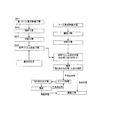
(光学表示ユニットの製造方法)
次に光学表示ユニットの製造方法について以下に説明する。図4に光学表示ユニットの製造方法のフローチャートを示す。
(Method for manufacturing optical display unit)
Next, a method for manufacturing the optical display unit will be described below. FIG. 4 shows a flowchart of a method for manufacturing the optical display unit.
(1)第1ロール原反準備工程(図4、S41)。長尺の第1シート製品を第1ロール原反として準備する。シート製品(第1、第2シート製品)の構成として、表面保護フィルム、偏光板、離型フィルムの積層構成を例にして説明する。離型フィルムは、粘着剤を介して偏光板の一方面に設けられ、表面保護フィルムは、粘着剤を介してその他方面の偏光板に設けられる。偏光板は、偏光子とその両面に設けられた偏光子保護フィルムとで構成される。それぞれの粘着剤は、層として形成されている。 (1) First roll original fabric preparation step (FIG. 4, S41). A long first sheet product is prepared as a first roll. As a configuration of the sheet product (first and second sheet products), a laminated configuration of a surface protective film, a polarizing plate, and a release film will be described as an example. The release film is provided on one surface of the polarizing plate via an adhesive, and the surface protective film is provided on the polarizing plate in the other direction via the adhesive. A polarizing plate is comprised with a polarizer and the polarizer protective film provided in the both surfaces. Each adhesive is formed as a layer.
(2)搬送工程(図4、S42)。第1ロール原反から第1シート製品を繰り出し、下流の工程に向けて搬送する。搬送手段の搬送機構は公知の手段で構成でき、例えば、複数のロール対によって挟持させ、ロール対の回転作用によって搬送させることができる。 (2) Transporting process (FIG. 4, S42). The first sheet product is unwound from the first roll and conveyed toward a downstream process. The transport mechanism of the transport means can be constituted by a known means, for example, can be sandwiched by a plurality of roll pairs and transported by the rotating action of the roll pairs.
(3)切断工程(図4、S43)。次いで、搬送手段によって搬送された第1シート製品は、切断手段を用いて、離型フィルムを切断せずに、第1シート製品の他の部材を所定サイズに切断する。これにより、離型フィルムを切断せずに、第1シート製品1のその他の部材である表面保護フィルム、粘着剤、偏光板、粘着剤を切断することができる。切断手段としては、例えば、レーザ装置、カッター、その他の公知の切断手段等が挙げられる。
(3) Cutting process (FIG. 4, S43). Next, the first sheet product conveyed by the conveying means uses the cutting means to cut other members of the first sheet product into a predetermined size without cutting the release film. Thereby, the surface protection film, an adhesive, a polarizing plate, and an adhesive which are other members of the
(4)貼合工程(図4、S44)。次いで、上記切断工程後に、離型フィルムを除去しながら、当該離型フィルムが除去された、上記で切断された第1シート製品を、粘着剤を介して基板に貼り合せる。基板としては、例えば、液晶セルのガラス基板、有機EL発光体基板等が挙げられる。また、基板は、貼り合わせ前に予め洗浄処理されるのが好ましい。 (4) Bonding process (FIG. 4, S44). Next, after the cutting step, while removing the release film, the first sheet product cut as described above from which the release film has been removed is bonded to the substrate via an adhesive. Examples of the substrate include a glass substrate of a liquid crystal cell and an organic EL light emitting substrate. Further, it is preferable that the substrate is cleaned in advance before bonding.
以上のそれぞれの工程は連続した製造ラインで実行される。そして、次の第2シート製品との切り替えの際にも連続して行えるように、第1シート製品の端面と、第2シート製品の端面とを連結するスプライス工程とを有している。このスプライス工程は、上述の連結方法を好適に適用できる。 Each of the above steps is performed on a continuous production line. And it has the splicing process which connects the end surface of the 1st sheet product, and the end surface of the 2nd sheet product so that it can carry out continuously also at the time of the change to the next 2nd sheet product. For this splicing step, the above-described connection method can be suitably applied.
また、以上の一連の製造工程では、基板の一方面に第1シート製品を貼り合わせたものである。その他面に別のシート製品を貼り合わせる工程も上述のように構成できる。 In the above series of manufacturing steps, the first sheet product is bonded to one side of the substrate. The process of bonding another sheet product to the other surface can also be configured as described above.
(5)また、上記の製造工程に、検査工程(図4)を有することが好ましい。検査工程としては、貼り合わせ状態を検査する検査工程と、貼り合わせ後の欠点を検査する検査工程が例示されるが、いずれか一方のみの検査でもよいが、両方の検査を行なうことが好ましい。 (5) Moreover, it is preferable to have an inspection process (FIG. 4) in said manufacturing process. Examples of the inspection process include an inspection process for inspecting the bonding state and an inspection process for inspecting defects after bonding, but only one of the inspections may be performed, but it is preferable to perform both inspections.
(6)検査工程において、良品判定された光学表示ユニットは、光学表示装置に実装される(実装工程)。不良品判定された場合、リワーク処理が施され、新たに光学フィルムが貼られ、次いで検査され、良品判定の場合、実装工程に移行し、不良品判定の場合、再度リワーク処理に移行するかあるいは廃棄処分とする。 (6) In the inspection process, the non-defective optical display unit is mounted on the optical display device (mounting process). If a defective product is determined, a rework process is performed, a new optical film is applied, and then inspected.If a good product is determined, the process proceeds to a mounting process. Dispose of.
(スキップカット方式)
また、上記切断工程の別実施形態を以下に説明する。第1ロール原反の幅方向の一方の端部には、所定ピッチ単位(例えば1000mm)に第1シート製品の欠点情報(欠点座標、欠点の種類、サイズ等)がコード情報(例えばQRコード、バーコード)として付されている場合がある。このような場合、切断する前段階で、このコード情報を読み取り、解析して欠点部分を避けるように、第1切断工程において所定サイズに切断する(スキップカットと称することがある)。そして、欠点を含む部分は除去あるいは基板ではない部材に貼り合わせるように構成し、所定サイズに切断された良品判定の枚葉のシート製品を基板に貼り合わされるように構成する。これにより、光学表示ユニットの歩留まりが大幅に向上される。
(Skip cut method)
Further, another embodiment of the cutting step will be described below. At one end in the width direction of the first roll of the first roll, the defect information (defect coordinates, defect type, size, etc.) of the first sheet product in a predetermined pitch unit (for example, 1000 mm) is code information (for example, QR code, (Barcode) may be attached. In such a case, before the cutting, this code information is read and analyzed, and cut into a predetermined size in the first cutting step so as to avoid the defective portion (sometimes referred to as skip cut). Then, the portion including the defect is removed or bonded to a member that is not a substrate, and the non-defective sheet product that has been cut into a predetermined size is bonded to the substrate. Thereby, the yield of the optical display unit is greatly improved.
(別実施形態)
次に別の光学表示ユニットの製造方法について以下に説明する。図5に光学表示ユニットの製造方法のフローチャートを示す。上述の製造方法と同様の工程については、その説明を簡単にあるいは省略して説明する。
(Another embodiment)
Next, another method for manufacturing an optical display unit will be described below. FIG. 5 shows a flowchart of a method for manufacturing the optical display unit. The same steps as those in the above manufacturing method will be described briefly or omitted.
(1)第1ロール原反準備工程(図5、S51)。長尺の第1シート製品を第1ロール原反として準備する。シート製品(第1、第2シート製品)の構成は、上述した構成と同じである。 (1) First roll original fabric preparation step (FIG. 5, S51). A long first sheet product is prepared as a first roll. The configuration of the sheet product (first and second sheet products) is the same as the configuration described above.
(2)搬送工程(図5、S52)。ロール原反準備工程の後に、前記ロール原反から第1シート製品を繰り出し下流に工程に搬送する(搬送工程)。 (2) Transfer process (FIG. 5, S52). After the roll original fabric preparation step, the first sheet product is fed out from the roll original fabric and conveyed downstream (process step).
(3)第1離型フィルム除去工程(図5、S53)。搬送されてきた第1シート製品から第1離型フィルムを除去する。第1離型フィルムの除去方法としては、例えば、剥離したフィルムをロールに巻くようにして連続的に剥離する方法、所定サイズ単位に第1離型フィルムのみをカットし粘着テープで剥離除去する方法、その他工程の除去方法等が挙げられる。 (3) 1st release film removal process (FIG. 5, S53). The first release film is removed from the conveyed first sheet product. As a method for removing the first release film, for example, a method in which the peeled film is continuously wound around a roll, or a method in which only the first release film is cut into a predetermined size unit and peeled off with an adhesive tape. In addition, a method for removing other processes may be used.
(4)欠点検査工程(図5、S54)。第1離型フィルム除去工程後に、欠点検査をする。第1離型フィルムに内在する位相差を考慮する必要がなく、光学フィルムの欠点検査を行なえる。欠点検査は公知の方法が適用できる。 (4) Defect inspection process (FIG. 5, S54). The defect inspection is performed after the first release film removing step. It is not necessary to consider the phase difference inherent in the first release film, and the defect inspection of the optical film can be performed. A known method can be applied to the defect inspection.
(5)第2離型フィルム貼合工程(図5、S55)。欠点検査工程後に、第2離型フィルムを、粘着剤を介して第1シート製品に貼り合せる。貼り合せに際し、気泡等の泡がみが生じないように行なうことが、平面性維持のため好ましい。 (5) 2nd release film bonding process (FIG. 5, S55). After the defect inspection step, the second release film is bonded to the first sheet product via an adhesive. In order to maintain flatness, it is preferable to perform the bonding so that bubbles such as bubbles do not occur.
(6)切断工程(図5、S56)。次いで、搬送手段によって搬送された第1シート製品は、切断手段を用いて、第2離型フィルムを切断せずに、第1シート製品の他の部材を所定サイズに切断する。 (6) Cutting process (FIG. 5, S56). Next, the first sheet product conveyed by the conveying means uses the cutting means to cut the other members of the first sheet product to a predetermined size without cutting the second release film.
(7)貼合工程(図5、S57)。次いで、上記切断工程後に、第2離型フィルムを除去しながら、当該第2離型フィルムが除去された第1シート製品を、粘着剤を介して基板に貼り合せる。 (7) Bonding process (FIG. 5, S57). Next, after the cutting step, the first sheet product from which the second release film has been removed is bonded to the substrate via an adhesive while removing the second release film.
以上のそれぞれの工程は連続した製造ラインで実行される。そして、次の第2シート製品との切り替えの際にも連続して行えるように、第1シート製品の端面と、第2シート製品の端面とを連結するスプライス工程とを有している。このスプライス工程は、上述の連結方法を好適に適用できる。 Each of the above steps is performed on a continuous production line. And it has the splicing process which connects the end surface of the 1st sheet product, and the end surface of the 2nd sheet product so that it can carry out continuously also at the time of the change to the next 2nd sheet product. For this splicing step, the above-described connection method can be suitably applied.
また、以上の一連の製造工程では、基板の一方面にシート製品を貼り合わせたものである。その他面に別のシート製品を貼り合わる工程も上述と同様に構成できる。検査工程(図5)、実装工程等は上述と同様である。 In the above series of manufacturing steps, a sheet product is bonded to one surface of the substrate. The process of attaching another sheet product to the other surface can also be configured in the same manner as described above. The inspection process (FIG. 5), the mounting process, and the like are the same as described above.
(光学表示ユニットの製造方法を実現する好適な製造システム)
以下に、上述の別の光学表示ユニットの製造方法を実現する好適な製造システムについて説明する。図6に製造システムの概略構成を示す。
(Suitable manufacturing system for realizing the manufacturing method of the optical display unit)
A suitable manufacturing system for realizing the above-described method for manufacturing another optical display unit will be described below. FIG. 6 shows a schematic configuration of the manufacturing system.
図6に示すように、製造システムは第1シート製品を基板に貼り合わせる第1製造部と、第1シート製品が貼り合された基板面と異なる面に、第2シート製品を貼り合わせる第2製造部を有している。第1、第2シート製品の構成は、上述の図1のシート製品と同様の構成である。 As shown in FIG. 6, the manufacturing system attaches the second sheet product to a surface different from the substrate surface to which the first sheet product is bonded, and the first manufacturing unit that bonds the first sheet product to the substrate. Has a manufacturing department. The configuration of the first and second sheet products is the same as that of the above-described sheet product of FIG.
第1製造部は、長尺の第1シート製品1の第1ロール原反を設置する設置手段と、第1ロール原反から第1シート製品1を繰り出し、搬送する搬送手段と、搬送されてきた第1シート製品1から第1離型フィルムを除去する第1離型フィルム除去手段と、第1離型フィルム除去後に、欠点検査をする欠点検査手段と、第1欠点検査後に、第2離型フィルムを、粘着剤を介して第1シート製品1に貼り合せる第2離型フィルム貼合手段と、第2離型フィルムを貼り合せた後に、当該第2離型フィルムを切断せずに、第1シート製品1を所定サイズに切断する切断手段と、切断処理後に、第2離型フィルムを除去しながら、当該第2離型フィルムが除去された第1シート製品を、粘着剤を介して基板に貼り合せる貼合手段と、それぞれの手段を連動させるように制御する第1制御手段とを有している。
The first manufacturing unit has been transported by an installation means for installing the first roll raw material of the long
第2製造部は、長尺の第2シート製品の第2ロール原反を設置する設置手段と、第2ロール原反から第2シート製品を繰り出し、搬送する搬送手段と、搬送されてきた第2シート製品から第3離型フィルムを除去する第3離型フィルム除去手段と、第3離型フィルム除去後に、欠点検査をする第2欠点検査手段と、第2欠点検査後に、第4離型フィルムを、粘着剤を介して第2シート製品に貼り合せる第4離型フィルム貼合手段と、第4離型フィルムを貼り合せた後に、当該第4離型フィルムを切断せずに、第2シート製品を所定サイズに切断する切断手段と、切断処理後に、第4離型フィルムを除去しながら、当該第4離型フィルムが除去された第2シート製品を、粘着剤を介して、基板の第1シート製品が貼り合わされている面と異なる面に貼り合せる貼合手段と、それぞれの手段を連動させるように制御する第2制御手段とを有している。 The second manufacturing unit includes an installation unit that installs the second roll original of the long second sheet product, a conveyance unit that feeds and conveys the second sheet product from the second roll original, and a second unit that has been conveyed A third release film removing means for removing the third release film from the two-sheet product; a second defect inspection means for inspecting defects after removing the third release film; and a fourth release after the second defect inspection. After the fourth release film laminating means for laminating the film to the second sheet product via the adhesive and the fourth release film are bonded together, the second release film is cut without cutting the fourth release film. A cutting means for cutting the sheet product into a predetermined size, and the second sheet product from which the fourth release film is removed while removing the fourth release film after the cutting process is performed on the substrate via the adhesive. Different from the side where the first sheet product is bonded And laminating means for laminating the, and a second control means for controlling so as to interlock the respective means.
第1製造部と第2製造部はそれぞれ単独に駆動されてもよいが、それぞれが連動するように駆動されてもよい。第1制御手段と第2制御手段によって、一連の処理工程を連動して駆動制御するように構成できる。なお、離型フィルム除去手段、欠点検査手段、離型フィルム貼合手段が省略された構成もできる。 The first manufacturing unit and the second manufacturing unit may be driven independently, but may be driven so as to be interlocked with each other. The first control means and the second control means can be configured to drive and control a series of processing steps in conjunction with each other. In addition, the structure by which the mold release film removal means, the defect inspection means, and the mold release film bonding means were abbreviate | omitted is also possible.
(第1製造部)
設置手段301は、長尺の第1シート製品1の第1ロール原反を設置し、自由回転あるいは一定の回転速度で回転するようにモータ等と連動されたローラ架台装置で構成される。第1制御手段によって回転速度が設定され、駆動制御される。
(First Production Department)
The installation means 301 is configured by a roller gantry device in which a first roll of the first
搬送手段302は、第1ロール原反から第1シート製品1を繰り出し、各処理工程に第1シート製品1を搬送する。各工程の要所において、テンションコントロールを設置する。搬送手段302は、第1制御手段によって制御されている。
The conveying means 302 feeds the
第1離型フィルム除去手段は、搬送されてきた第1シート製品1から第1離型フィルムを剥離除去し、ロール状に巻き取る構成である。ロールへの巻取り速度は第1制御手段によって制御されている。剥離機構としては、先端が先鋭なナイフエッジを有し、このナイフエッジに第1離型フィルムを巻き掛けて反転移送することにより、第1離型フィルムを剥離除去すると共に、第1離型フィルムを剥離した後の第1シート製品1を搬送方向に搬送するように構成される。
The first release film removing means is configured to peel and remove the first release film from the conveyed
欠点検査手段303は、第1離型フィルム除去後に、欠点検査をする。欠点検査手段303はCCDカメラあるはCMOSカメラであり、取得された画像データは第1制御手段に送信される。第1制御手段は、画像データを解析し、欠点を検出し、さらにその位置座標を算出する。この欠点の位置座標は、後述の切断手段によるスキップカットに提供される。 The defect inspection means 303 performs defect inspection after removing the first release film. The defect inspection means 303 is a CCD camera or a CMOS camera, and the acquired image data is transmitted to the first control means. The first control means analyzes the image data, detects a defect, and calculates its position coordinates. The position coordinates of this defect are provided for the skip cut by the cutting means described later.
第2離型フィルム貼合手段は、欠点検査後に、第2離型フィルムを、粘着剤を介して第1シート製品に貼り合せる。図6に示すように、第2離型フィルムのロール原反から第2離型フィルムを繰り出し、1または複数のローラ対で、第2離型フィルムと第1シート製品を挟持し、当該ローラ対で所定の圧力を作用させて貼り合わせる。ローラ対の回転速度、圧力制御、搬送制御は、第1制御手段によって制御される。 The second release film bonding means bonds the second release film to the first sheet product via the adhesive after the defect inspection. As shown in FIG. 6, the second release film is unwound from the roll original fabric of the second release film, and the second release film and the first sheet product are sandwiched by one or a plurality of roller pairs, and the roller pair Apply a predetermined pressure and stick together. The rotation speed, pressure control, and conveyance control of the roller pair are controlled by the first control means.
切断手段304は、第2離型フィルムを貼り合せた後に、当該第2離型フィルムを切断せずに、第1シート製品1を所定サイズに切断する。切断手段304は、レーザ装置である。欠点検査処理で検出された欠点の位置座標に基づいて、切断手段304は、欠点部分を避けるように所定サイズに切断する。すなわち、欠点部分を含む切断品は不良品として後工程で排除される。あるいは、切断手段304は、欠点の存在を無視して、連続的に所定サイズに切断してもよい。この場合、後述の貼り合せ処理において、当該部分を貼り合せずに除去あるいは仮板ユニットに貼り合わせるように構成できる。この場合の制御も第1制御手段の機能による。
The cutting means 304 cuts the
また、切断手段304は、第1シート製品1を裏面から吸着保持する保持テーブルを配置し、レーザ装置を第1シート製品1の上方に備える。第1シート製品1の幅方向にレーザを走査させるように水平移動し、最下部の第2離型フィルムを切断せずに、第1シート製品をその搬送方向に所定ピッチで切断する。なお、この切断を、「ハーフカット」と称することがある。また、このレーザ装置は、第1シート製品1の幅方向から挟むようにして、切断部位に向けて温風を吹き付けるエアーノズルと、この温風により搬送される切断部位から発生したガス(煙)を集煙する集煙ダクトとが対向した状態で一体構成されていることが好ましい。第1シート製品1を保持テーブルで吸着する場合に、その下流側と上流側の第1シート製品1の連続搬送を停止しないように、搬送機構の段差ローラ302a、302bは上下垂直方向に移動するように構成されている。この動作も第1制御手段の制御による。
Further, the cutting means 304 is provided with a holding table that holds the
貼合手段は、切断処理後に、第2離型フィルムを除去しながら、当該第2離型フィルムが除去された第1シート製品1を、粘着剤を介して基板Wに貼り合せる。貼り合せる場合に、押さえローラ305によって、第1シート製品1を基板W面に圧接しながら貼り合わせる。押さえローラ305の押さえ圧力、動作は、第1制御手段によって制御される。剥離機構としては、先端が先鋭なナイフエッジを有し、このナイフエッジに第2離型フィルムを巻き掛けて反転移送することにより、第2離型フィルムを剥離除去すると共に、第2離型フィルムを剥離した後の第1シート製品1を基板W面に送り出すように構成される。この際に、第2離型フィルムに150N/m以上1000N/m以下の張力をかけた状態および/または、第1シート製品を第2離型フィルムが除去されてから基板W面に圧接するまでの時間を3秒以内で行なうことにより、第1シート製品1の貼り合わせ精度を向上させることができる。張力が150N/mより小さいと第1シート製品1の送り出し位置が安定せず、1000N/mより大きいと第2離型フィルムが伸びて破断するおそれがあり、圧接するまでの時間が3秒よりも長いと、第2離型フィルムから剥離された第1シート製品端部が湾曲して折れや気泡が発生するおそれがある。貼合せ機構としては、押さえロ一ラ305とそれに対向して配置される案内ローラとから構成されている。案内ローラは、モータ駆動されるゴムローラで構成され、その直上方にはモータ駆動される金属ローラからなる押さえローラ305が昇降可能に配備されており、基板Wを貼合せ位置に送り込む際には押さえローラ305はその上面より高い位置まで上昇されてローラ間隔を開けるようになっている。なお、案内ローラおよび押さえローラ305は、いずれもゴムローラであってもよいし金属ローラであってもよい。基板Wは予め洗浄手段で洗浄され、ストック部にストックされている。吸着搬送手段306によって、搬送機構に配置される。この制御も第1制御手段の制御による。
The bonding means bonds the
(第2製造部)
第1製造部から搬送された基板W1は、搬送過程において、或いは第2製造部において、基板W1は上下反転される。上下反転手段(不図示)は、上面から吸着手段で基板W1を吸着し、持ち上げ、上下を反転させて、搬送機構に再度配置させるように構成される。この制御は、第2制御手段の機能による。なお、別実施形態として、上下反転処理を行なわない構成も可能である。この場合、第2製造部において、第2シート製品を通常と異なり、反転させた状態で(離型フィルムが上面となるようにして)各工程を処理し、第2シート製品を基板W1の下側から貼り合わせるように構成される。なお、第2シート製品の偏光板を前記第1シート製品の偏光板と90°の関係(クロスニコルの関係)に貼り合わせる場合は、基板Wを90°回転させてから第2シート製品が貼り合わされる。第2製造部の各工程において、設置手段、搬送手段、第3離型フィルム除去手段、欠点検査手段、第4離型フィルム貼合手段、切断手段は、第1製造部の対応する手段と同様の構成であるため、説明は省略する。
(Second manufacturing department)
The substrate W1 transferred from the first manufacturing unit is turned upside down in the transfer process or in the second manufacturing unit. The upside down means (not shown) is configured to suck the substrate W1 from the upper surface by the suction means, lift it, turn it upside down, and place it again on the transport mechanism. This control depends on the function of the second control means. As another embodiment, a configuration in which the upside down process is not performed is also possible. In this case, in the second manufacturing department, each step is processed in a state where the second sheet product is inverted unlike normal (with the release film on the upper surface), and the second sheet product is placed under the substrate W1. It is configured to be bonded from the side. When the polarizing plate of the second sheet product is bonded to the polarizing plate of the first sheet product in a 90 ° relationship (cross Nicol relationship), the substrate W is rotated 90 ° before the second sheet product is attached. Combined. In each process of the second manufacturing section, the installation means, the conveying means, the third release film removing means, the defect inspection means, the fourth release film laminating means, and the cutting means are the same as the corresponding means of the first manufacturing section. Since it is the structure of this, description is abbreviate | omitted.
第1制御手段、第2制御手段は、各工程の上記手段を連動するように制御する。それぞれの動作タイミングは、所定の位置にセンサを配置したり、搬送機構の回転部材をロータリーエンコーダ等で検出するようにして算出される。第1、第2制御手段は、ソフトウエアプログラムとCPU、メモリ等のハードウエア資源との協同作用によって実現されてもよく、この場合プログラムソフトウエア、処理手順、各種設定等はメモリが予め記憶されている。また、専用回路やファームウエア等で構成できる。 A 1st control means and a 2nd control means control so that the said means of each process may be interlocked. Each operation timing is calculated by arranging a sensor at a predetermined position or detecting a rotating member of the transport mechanism with a rotary encoder or the like. The first and second control means may be realized by the cooperation of a software program and a hardware resource such as a CPU and a memory. In this case, the program software, processing procedure, various settings, etc. are stored in the memory in advance. ing. Further, it can be configured by a dedicated circuit or firmware.
(別実施形態)
上記実施例では、欠点部分を含むシート製品は、仮板ユニットに貼り合わせて回収していたが、帯状のセパレータに貼り合わせて巻取り回収するように構成してもよい。
(Another embodiment)
In the above embodiment, the sheet product including the defective portion is collected by being bonded to the temporary plate unit. However, the sheet product may be bonded to the strip-shaped separator and wound and recovered.
欠点検査は公知の欠点検査方法が適用できる。欠点検査方法としては、例えば、自動検査装置及び検査者による目視検査が挙げられる。自動検査装置は、シート製品の欠点(欠陥とも称される)を自動で検査する装置であり、光を照射し、その反射光像や透過光像をラインセンサーや2次元TVカメラなどの撮像部を介して取得し、取得された画像データに基づいて、欠点検出を行う。また、光源と撮像部の間の光路中に検査用偏光フィルタを介在させた状態で画像データを取得する。通常、この検査用偏光フィルタの偏光軸(例えば、偏光吸収軸)は、検査対象である偏光板の偏光軸(例えば、偏光吸収軸)と直交する状態(クロスニコル)となるように配置される。クロスニコルに配置することで、仮に欠点が存在しなければ撮像部から全面黒の画像が入力されるが、欠点が存在すれば、その部分が黒にならない(輝点として認識される)。従って、適宜のしきい値を設定することで、欠点を検出することができる。このような輝点検出では、表面付着物、内部の異物等の欠点が輝点として検出される。また、この輝点検出のほかに、対象物に対して透過光画像をCCD撮像し画像解析することで異物検出する方法もある。また、対象物に対して反射光画像をCCD撮像し画像解析することで表面付着異物を検出する方法もある。 A known defect inspection method can be applied to the defect inspection. Examples of the defect inspection method include an automatic inspection device and a visual inspection by an inspector. The automatic inspection apparatus is an apparatus that automatically inspects defects (also referred to as defects) of a sheet product. The automatic inspection apparatus emits light, and the reflected light image and the transmitted light image are image sensors such as a line sensor and a two-dimensional TV camera. The defect detection is performed based on the acquired image data. Further, the image data is acquired in a state where the inspection polarizing filter is interposed in the optical path between the light source and the imaging unit. Usually, the polarization axis (for example, the polarization absorption axis) of the polarizing filter for inspection is arranged to be in a state (crossed Nicols) orthogonal to the polarization axis (for example, the polarization absorption axis) of the polarizing plate to be inspected. . By arranging in crossed Nicols, a black image is input from the imaging unit if there is no defect, but if there is a defect, that part will not be black (recognized as a bright spot). Therefore, a defect can be detected by setting an appropriate threshold value. In such bright spot detection, defects such as surface deposits and internal foreign matter are detected as bright spots. In addition to this bright spot detection, there is also a method of detecting a foreign object by CCD imaging a transmitted light image on an object and analyzing the image. There is also a method for detecting a surface-attached foreign substance by subjecting an object to a reflected light image by CCD imaging and analyzing the image.
(実施例1)
上記連結方法を用いて、連結シート製品の製造、および光学表示ユニットの製造を行なった。シート製品は、表面保護フィルム(PETフィルム)、アクリル系粘着剤層、偏光板、アクリル系粘着剤層、離型フィルム(積層面にシリコーン処理されたPETフィルム)の積層構成である。偏光板は、延伸、染色されたポリビニルアルコールフィルムの偏光子に、その両面側に、トリアセチルセルロースフィルムが接着剤を介して設けられた構成である。連結部材として、接着テープ(日東電工製ダンプロンテープNo.3041)を用いた。この接着テープは、幅10cm、その厚み70μm、接着力7N/25mm、引張り強度120N/25mm、伸び率140%である。各種試験方法は、上述したものと同様である。図1のように連結部材を用いてシート製品を連結した。その結果、連結部分での切れもなく2つのシート製品を連結でき、離型フィルムを他の構成部材に干渉することなく、滑らかに剥がして、液晶セル基板に貼着することができた。また、一方の接着テープと第2シート製品の離型フィルム(積層面にシリコーン処理されたPETフィルム)との接着力(A)が3.5N/25mm、第2シート製品の離型フィルム(積層面にシリコーン処理されたPETフィルム)と粘着剤層との接着力(B)が0.02N/25mm、他方の接着テープと第2シート製品の表面保護フィルム(PETフィルム)との接着力(C)が3.5N/25mmであり、上述の数式1のC≧A>Bの関係が成立した。
Example 1
Using the above connection method, a connection sheet product and an optical display unit were manufactured. The sheet product has a laminated structure of a surface protective film (PET film), an acrylic pressure-sensitive adhesive layer, a polarizing plate, an acrylic pressure-sensitive adhesive layer, and a release film (PET film silicone-treated on the laminated surface). The polarizing plate has a configuration in which a triacetyl cellulose film is provided on both sides of a polarizer of a stretched and dyed polyvinyl alcohol film via an adhesive. As the connecting member, an adhesive tape (Nitto Denko Ducron Tape No. 3041) was used. This adhesive tape has a width of 10 cm, a thickness of 70 μm, an adhesive strength of 7 N / 25 mm, a tensile strength of 120 N / 25 mm, and an elongation of 140%. Various test methods are the same as those described above. The sheet product was connected using a connecting member as shown in FIG. As a result, the two sheet products could be connected without any break at the connecting portion, and the release film could be smoothly peeled off and adhered to the liquid crystal cell substrate without interfering with other components. Also, the adhesive strength (A) between one adhesive tape and the release film of the second sheet product (PET film with silicone treatment on the laminated surface) is 3.5 N / 25 mm, the release film of the second sheet product (lamination Adhesive force (B) between the PET film silicone-treated on the surface and the pressure-sensitive adhesive layer is 0.02 N / 25 mm. Adhesive force between the other adhesive tape and the surface protective film (PET film) of the second sheet product (C ) Is 3.5 N / 25 mm, and the relationship of C ≧ A> B in the above-described
(実施例2)
実施例2の連結方法を図3に示す。シート製品の構成は、実施例1と同様である。第1シート製品と第2シート製品の端面同士を対向させ、このシート製品同士を対向させた部分の両表面を、熱溶着用のコテで押さえ、コテと接触するシート表面部分501、502を熱溶着させ、次いで、コテを外して、その熱溶着部分を固着させて連結した。この結果得られた連結シート製品は、連結部分の機械強度の面で、実施例1より若干劣るものの、連結部分での切れもなく2つのシート製品を連結でき、離型フィルムを他の構成部材に干渉することなく、滑らかに剥がして、液晶セル基板に貼着することができた。
(Example 2)
The connection method of Example 2 is shown in FIG. The configuration of the sheet product is the same as that of the first embodiment. The end surfaces of the first sheet product and the second sheet product are made to face each other, and both surfaces of the parts where the sheet products are made to face each other are pressed with a hot welding iron to heat the
(光学部材)
前記においても、光学部材を構成する偏光子、および偏光子の片側または両側に用いられるフィルムについては一部説明しているが、一般的には、以下の材料を例示できる。
(Optical member)
In the above description, part of the polarizer constituting the optical member and the film used on one side or both sides of the polarizer have been described, but generally, the following materials can be exemplified.
(偏光子)
ポリビニルアルコール系フィルムの染色、架橋、延伸の各処理は、別々に行う必要はなく同時に行ってもよく、また、各処理の順番も任意でよい。なお、ポリビニルアルコール系フィルムとして、膨潤処理を施したポリビニルアルコール系フィルムを用いてもよい。一般には、ポリビニルアルコール系フィルムを、ヨウ素や二色性色素を含む溶液に浸漬し、ヨウ素や二色性色素を吸着させて染色した後洗浄し、ホウ酸やホウ砂等を含む溶液中で延伸倍率3倍〜7倍で一軸延伸した後、乾燥する。ヨウ素や二色性色素を含む溶液中で延伸した後、ホウ酸やホウ砂等を含む溶液中でさらに延伸(二段延伸)した後、乾燥することにより、ヨウ素の配向が高くなり、偏光度特性が良くなるため、特に好ましい。
(Polarizer)
Each treatment of dyeing, crosslinking and stretching of the polyvinyl alcohol film need not be performed separately and may be performed simultaneously, and the order of the treatments may be arbitrary. In addition, you may use the polyvinyl alcohol-type film which gave the swelling process as a polyvinyl-alcohol-type film. Generally, a polyvinyl alcohol film is immersed in a solution containing iodine or a dichroic dye, dyed by adsorbing iodine or a dichroic dye, washed, and stretched in a solution containing boric acid or borax. After uniaxial stretching at a magnification of 3 to 7 times, it is dried. After stretching in a solution containing iodine or dichroic dye, further stretching (two-stage stretching) in a solution containing boric acid or borax, etc., and then drying, the orientation of iodine increases, and the degree of polarization This is particularly preferable because the characteristics are improved.
上記のポリビニルアルコール系ポリマーとしては、例えば、酢酸ビニルを重合した後にケン化したものや、酢酸ビニルに少量の不飽和カルボン酸、不飽和スルホン酸、カチオン性モノマー等の共重合可能なモノマーを共重合したもの、等が挙げられる。ポリビニルアルコール系ポリマーの平均重合度は、特に制限されず任意のものを使用することができるが、1000以上が好ましく、より好ましくは2000〜5000である。また、ポリビニルアルコール系ポリマーのケン化度は85モル%以上が好ましく、より好ましくは98〜100モル%である。 Examples of the polyvinyl alcohol polymer include those obtained by polymerizing vinyl acetate and then saponifying vinyl acetate and a small amount of a copolymerizable monomer such as unsaturated carboxylic acid, unsaturated sulfonic acid, and cationic monomer. Polymerized products and the like can be mentioned. The average degree of polymerization of the polyvinyl alcohol polymer is not particularly limited, and any one can be used, but 1000 or more is preferable, and 2000-5000 is more preferable. Moreover, 85 mol% or more is preferable and, as for the saponification degree of a polyvinyl alcohol-type polymer, More preferably, it is 98-100 mol%.
製造される偏光子の厚さは、5〜80μmが一般的であるが、これに限定するものではなく、また、偏光子の厚さを調整する方法に関しても、特に限定するものではなく、テンター、ロール延伸や圧延等の通常の方法を用いることができる。 The thickness of the manufactured polarizer is generally 5 to 80 μm, but is not limited thereto, and the method for adjusting the thickness of the polarizer is not particularly limited. Ordinary methods such as roll stretching and rolling can be used.
偏光子と保護層である透明の偏光子保護フィルムとの接着処理は、特に限定されるものではないが、例えば、ビニルアルコール系ポリマーからなる接着剤、あるいは、ホウ酸やホウ砂、グルタルアルデヒドやメラミン、シュウ酸などのビニルアルコール系ポリマーの水溶性架橋剤から少なくともなる接着剤等を介して行うことができる。かかる接着層は、水溶液の塗布乾燥層等として形成されるが、その水溶液の調製に際しては必要に応じて、他の添加剤や、酸等の触媒も配合することができる。 The adhesion treatment between the polarizer and the transparent polarizer protective film as the protective layer is not particularly limited, but for example, an adhesive made of a vinyl alcohol polymer, boric acid, borax, glutaraldehyde, It can be carried out via an adhesive comprising at least a water-soluble crosslinking agent of a vinyl alcohol polymer such as melamine or oxalic acid. Such an adhesive layer is formed as a coating / drying layer or the like of an aqueous solution. When preparing the aqueous solution, other additives and a catalyst such as an acid can be blended as necessary.
(偏光子保護フィルム)
偏光子の片側又は両側に設ける偏光子保護フィルムには、適宜な透明フィルムを用いることができる。例えば透明性、機械的強度、熱安定性、水分遮断性、等方性などに優れる熱可塑性樹脂が用いられる。このような熱可塑性樹脂の具体例としては、トリアセチルセルロース等のセルロース樹脂、ポリエステル樹脂、ポリエーテルスルホン樹脂、ポリスルホン樹脂、ポリカーボネート樹脂、ポリアミド樹脂、ポリイミド樹脂、ポリオレフィン樹脂、(メタ)アクリル樹脂、環状ポリオレフィン樹脂(ノルボルネン系樹脂)、ポリアリレート樹脂、ポリスチレン樹脂、ポリビニルアルコール樹脂、およびこれらの混合物があげられる。なお、偏光子の片側には、透明保護フィルムが接着剤層により貼り合わされるが、他の片側には、透明保護フィルムとして、(メタ)アクリル系、ウレタン系、アクリルウレタン系、エポキシ系、シリコーン系等の熱硬化性樹脂または紫外線硬化型樹脂を用いることができる。透明保護フィルム中には任意の適切な添加剤が1種類以上含まれていてもよい。添加剤としては、例えば、紫外線吸収剤、酸化防止剤、滑剤、可塑剤、離型剤、着色防止剤、難燃剤、核剤、帯電防止剤、顔料、着色剤などがあげられる。透明保護フィルム中の上記熱可塑性樹脂の含有量は、好ましくは50〜100重量%、より好ましくは50〜99重量%、さらに好ましくは60〜98重量%、特に好ましくは70〜97重量%である。透明保護フィルム中の上記熱可塑性樹脂の含有量が50重量%以下の場合、熱可塑性樹脂が本来有する高透明性等が十分に発現できないおそれがある。また、非晶性POフィルム、シクロオレフィンポリマー(COP)系フィルム、アートンフィルム(JSR製)、ゼオノアフィルム(日本ゼオン製)等が挙げられる。
(Polarizer protective film)
An appropriate transparent film can be used for the polarizer protective film provided on one side or both sides of the polarizer. For example, a thermoplastic resin excellent in transparency, mechanical strength, thermal stability, moisture barrier property, isotropy, etc. is used. Specific examples of such thermoplastic resins include cellulose resins such as triacetyl cellulose, polyester resins, polyethersulfone resins, polysulfone resins, polycarbonate resins, polyamide resins, polyimide resins, polyolefin resins, (meth) acrylic resins, cyclic Examples thereof include polyolefin resins (norbornene resins), polyarylate resins, polystyrene resins, polyvinyl alcohol resins, and mixtures thereof. A transparent protective film is bonded to one side of the polarizer by an adhesive layer. On the other side, as a transparent protective film, (meth) acrylic, urethane-based, acrylurethane-based, epoxy-based, silicone A thermosetting resin such as a system or an ultraviolet curable resin can be used. One or more kinds of arbitrary appropriate additives may be contained in the transparent protective film. Examples of the additive include an ultraviolet absorber, an antioxidant, a lubricant, a plasticizer, a release agent, a coloring inhibitor, a flame retardant, a nucleating agent, an antistatic agent, a pigment, and a coloring agent. The content of the thermoplastic resin in the transparent protective film is preferably 50 to 100% by weight, more preferably 50 to 99% by weight, still more preferably 60 to 98% by weight, and particularly preferably 70 to 97% by weight. . When content of the said thermoplastic resin in a transparent protective film is 50 weight% or less, there exists a possibility that the high transparency etc. which a thermoplastic resin originally has cannot fully be expressed. Moreover, an amorphous PO film, a cycloolefin polymer (COP) film, an Arton film (manufactured by JSR), a ZEONOR film (manufactured by Nippon Zeon) and the like can be mentioned.
また、上記の透明保護フィルムとしては、特開2001−343529号公報(WO01/37007)に記載のポリマーフィルム、例えば、(A)側鎖に置換および/または非置換イミド基を有する熱可塑性樹脂と、(B)側鎖に置換および/または非置換フェニルならびにニトリル基を有する熱可塑性樹脂を含有する樹脂組成物があげられる。具体例としてはイソブチレンとN−メチルマレイミドからなる交互共重合体とアクリロニトリル・スチレン共重合体とを含有する樹脂組成物のフィルムがあげられる。フィルムは樹脂組成物の混合押出品などからなるフィルムを用いることができる。これらのフィルムは位相差が小さく、光弾性係数が小さいため偏光板の歪みによるムラなどの不具合を解消することができ、また透湿度が小さいため、加湿耐久性に優れる。 Moreover, as said transparent protective film, the polymer film of Unexamined-Japanese-Patent No. 2001-343529 (WO01 / 37007), for example, (A) The thermoplastic resin which has a substituted and / or unsubstituted imide group in a side chain, (B) A resin composition containing a thermoplastic resin having a substituted and / or unsubstituted phenyl and a nitrile group in the side chain. A specific example is a film of a resin composition containing an alternating copolymer composed of isobutylene and N-methylmaleimide and an acrylonitrile / styrene copolymer. As the film, a film made of a mixed extruded product of the resin composition or the like can be used. Since these films have a small phase difference and a small photoelastic coefficient, problems such as unevenness due to the distortion of the polarizing plate can be eliminated, and since the moisture permeability is small, the humidification durability is excellent.
また、上記の透明保護フィルムの厚さは、適宜に決定しうるが、一般には強度や取扱性等の作業性、薄層性などの点より1〜500μm程度である。特に1〜300μmが好ましく、5〜200μmがより好ましい。透明保護フィルムは、5〜150μmの場合に特に好適である。 Moreover, although the thickness of said transparent protective film can be determined suitably, generally it is about 1-500 micrometers from points, such as workability | operativity, such as intensity | strength and a handleability, and thin layer property. 1-300 micrometers is especially preferable, and 5-200 micrometers is more preferable. The transparent protective film is particularly suitable when the thickness is 5 to 150 μm.
光学フィルムは、実用に際して各種光学層を積層した多層積層構造の光学フィルムも例示できる。その光学層については特に限定されるものではないが、例えば、前記透明保護フィルムの偏光子を接着させない面(前記接着剤塗布層を設けない面)に対して、ハードコート処理や反射防止処理、スティッキング防止や、拡散ないしアンチグレアを目的とした表面処理を施したり、視角補償等を目的とした配向液晶層を積層する方法があげられる。また、反射板や半透過板、位相差板(1/2や1/4等の波長板(λ板)を含む)、視角補償フィルムなどの液晶表示装置等の形成に用いられる光学フィルムを1層または2層以上貼りあわせたものもあげられる。 The optical film can also be exemplified by an optical film having a multilayer laminated structure in which various optical layers are laminated in practical use. The optical layer is not particularly limited, for example, on the surface of the transparent protective film that does not adhere the polarizer (the surface on which the adhesive coating layer is not provided), hard coat treatment or antireflection treatment, Examples thereof include a method of applying a surface treatment for the purpose of preventing sticking, diffusion or antiglare, and laminating an alignment liquid crystal layer for the purpose of viewing angle compensation or the like. Further, an optical film used for forming a liquid crystal display device such as a reflection plate, a semi-transmission plate, a phase difference plate (including a wave plate (λ plate) such as 1/2 or 1/4), a viewing angle compensation film, etc. A layer or a laminate of two or more layers is also included.
(位相差板)
偏光子に積層される光学フィルムの一例として位相差板が挙げられる。位相差板としては、高分子材料を一軸または二軸延伸処理してなる複屈折性フィルム、液晶ポリマーの配向フィルム、液晶ポリマーの配向層をフィルムにて支持したものなどがあげられる。延伸処理は、例えばロール延伸法、長間隙沿延伸法、テンター延伸法、チューブラー延伸法などにより行うことができる。延伸倍率は、一軸延伸の場合には1.1〜3倍程度が一般的である。位相差板の厚さも特に制限されないが、一般的には10〜200μm、好ましくは20〜100μmである。
(Phase difference plate)
An example of the optical film laminated on the polarizer is a retardation plate. Examples of the retardation plate include a birefringent film obtained by uniaxially or biaxially stretching a polymer material, a liquid crystal polymer alignment film, and a liquid crystal polymer alignment layer supported by a film. The stretching treatment can be performed by, for example, a roll stretching method, a long gap stretching method, a tenter stretching method, a tubular stretching method, or the like. In the case of uniaxial stretching, the stretching ratio is generally about 1.1 to 3 times. The thickness of the retardation plate is not particularly limited, but is generally 10 to 200 μm, preferably 20 to 100 μm.
前記高分子材料としては、例えば、ポリビニルアルコール、ポリビニルブチラール、ポリメチルビニルエーテル、ポリヒドロキシエチルアクリレート、ヒドロキシエチルセルロース、ヒドロキシプロピルセルロース、メチルセルロース、ポリカーボネート、ポリアリレート、ポリスルホン、ポリエチレンテレフタレート、ポリエチレンナフタレート、ポリエーテルスルホン、ポリフェニレンスルファイド、ポリフェニレンオキサイド、ポリアリルスルホン、ポリビニルアルコール、ポリアミド、ポリイミド、ポリオレフィン、ポリ塩化ビニル、セルロース系重合体、またはこれらの二元系、三元系各種共重合体、グラフト共重合体、ブレンド物などがあげられる。これら高分子素材は延伸等により配向物(延伸フィルム)となる。 Examples of the polymer material include polyvinyl alcohol, polyvinyl butyral, polymethyl vinyl ether, polyhydroxyethyl acrylate, hydroxyethyl cellulose, hydroxypropyl cellulose, methyl cellulose, polycarbonate, polyarylate, polysulfone, polyethylene terephthalate, polyethylene naphthalate, and polyether sulfone. , Polyphenylene sulfide, polyphenylene oxide, polyallylsulfone, polyvinyl alcohol, polyamide, polyimide, polyolefin, polyvinyl chloride, cellulosic polymers, or binary, ternary various copolymers, graft copolymers, Examples include blends. These polymer materials become oriented products (stretched films) by stretching or the like.
(視角補償フィルム)
また、偏光子に積層される光学フィルムの一例として視角補償フィルムがある。視角補償フィルムは、液晶表示装置の画面を、画面に垂直でなくやや斜めの方向から見た場合でも、画像が比較的鮮明にみえるように視野角を広げるためのフィルムである。このような視角補償位相差板としては、例えば位相差フィルム、液晶ポリマー等の配向フィルムや透明基材上に液晶ポリマー等の配向層を支持したものなどからなる。通常の位相差板は、その面方向に一軸に延伸された複屈折を有するポリマーフィルムが用いられるのに対し、視角補償フィルムとして用いられる位相差板には、面方向に二軸に延伸された複屈折を有するポリマーフィルムとか、面方向に一軸に延伸され厚さ方向にも延伸された厚さ方向の屈折率を制御した複屈折を有するポリマーや傾斜配向フィルムのような二方向延伸フィルムなどが用いられる。傾斜配向フィルムとしては、例えばポリマーフィルムに熱収縮フィルムを接着して加熱によるその収縮力の作用下にポリマーフィルムを延伸処理又は/及び収縮処理したものや、液晶ポリマーを斜め配向させたものなどが挙げられる。位相差板の素材原料ポリマーは、先の位相差板で説明したポリマーと同様のものが用いられ、液晶セルによる位相差に基づく視認角の変化による着色等の防止や良視認の視野角の拡大などを目的とした適宜なものを用いうる。
(Viewing angle compensation film)
An example of the optical film laminated on the polarizer is a viewing angle compensation film. The viewing angle compensation film is a film for widening the viewing angle so that an image can be seen relatively clearly even when the screen of the liquid crystal display device is viewed from a slightly oblique direction rather than perpendicular to the screen. As such a viewing angle compensation phase difference plate, for example, a retardation film, an alignment film such as a liquid crystal polymer, or an alignment layer such as a liquid crystal polymer supported on a transparent substrate is used. A normal retardation plate uses a birefringent polymer film uniaxially stretched in the plane direction, whereas a retardation plate used as a viewing angle compensation film stretches biaxially in the plane direction. Birefringent polymer film, biaxially stretched film such as polymer with birefringence with a controlled refractive index in the thickness direction that is uniaxially stretched in the plane direction and stretched in the thickness direction, etc. Used. Examples of the inclined alignment film include a film obtained by bonding a heat shrink film to a polymer film and stretching or / and shrinking the polymer film under the action of the contraction force by heating, and a film obtained by obliquely aligning a liquid crystal polymer. Can be mentioned. The raw material polymer for the phase difference plate is the same as the polymer described in the previous phase difference plate, preventing coloration due to a change in the viewing angle based on the phase difference by the liquid crystal cell and expanding the viewing angle for good visual recognition. An appropriate one for the purpose can be used.
また良視認の広い視野角を達成する点などより、液晶ポリマーの配向層、特にディスコティック液晶ポリマーの傾斜配向層からなる光学的異方性層をトリアセチルセルロースフィルムにて支持した光学補償位相差板が好ましく用いうる。 Also, from the viewpoint of achieving a wide viewing angle with good visibility, an optically compensated phase difference in which a liquid crystal polymer alignment layer, in particular an optically anisotropic layer composed of a discotic liquid crystal polymer gradient alignment layer, is supported by a triacetylcellulose film. A plate can be preferably used.
(輝度向上フィルム)
偏光板と輝度向上フィルムを貼り合わせた偏光板は、通常液晶セルの裏側サイドに設けられて使用される。輝度向上フィルムは、液晶表示装置などのバックライトや裏側からの反射などにより自然光が入射すると所定偏光軸の直線偏光または所定方向の円偏光を反射し、他の光は透過する特性を示すもので、輝度向上フィルムを偏光板と積層した偏光板は、バックライト等の光源からの光を入射させて所定偏光状態の透過光を得ると共に、前記所定偏光状態以外の光は透過せずに反射される。この輝度向上フィルム面で反射した光を更にその後ろ側に設けられた反射層等を介し反転させて輝度向上フィルムに再入射させ、その一部又は全部を所定偏光状態の光として透過させて輝度向上フィルムを透過する光の増量を図ると共に、偏光子に吸収させにくい偏光を供給して液晶表示画像表示等に利用しうる光量の増大を図ることにより輝度を向上させうるものである。
(Brightness enhancement film)
A polarizing plate obtained by bonding a polarizing plate and a brightness enhancement film is usually provided on the back side of a liquid crystal cell. The brightness enhancement film reflects a linearly polarized light with a predetermined polarization axis or a circularly polarized light in a predetermined direction when natural light is incident due to a backlight such as a liquid crystal display device or reflection from the back side, and transmits other light. In addition, a polarizing plate in which a brightness enhancement film is laminated with a polarizing plate allows light from a light source such as a backlight to enter to obtain transmitted light in a predetermined polarization state, and reflects light without transmitting the light other than the predetermined polarization state. The The light reflected on the surface of the brightness enhancement film is further inverted through a reflective layer or the like provided behind the brightness enhancement film and re-incident on the brightness enhancement film, and part or all of the light is transmitted as light having a predetermined polarization state. Luminance can be improved by increasing the amount of light transmitted through the enhancement film and increasing the amount of light that can be used for liquid crystal display image display or the like by supplying polarized light that is difficult to be absorbed by the polarizer.
前記の輝度向上フィルムとしては、例えば誘電体の多層薄膜や屈折率異方性が相違する薄膜フィルムの多層積層体の如き、所定偏光軸の直線偏光を透過して他の光は反射する特性を示すもの、コレステリック液晶ポリマーの配向フィルムやその配向液晶層をフィルム基材上に支持したものの如き、左回り又は右回りのいずれか一方の円偏光を反射して他の光は透過する特性を示すものなどの適宜なものを用いうる。 The brightness enhancement film has a characteristic of transmitting linearly polarized light having a predetermined polarization axis and reflecting other light, such as a multilayer thin film of dielectric material or a multilayer laminate of thin film films having different refractive index anisotropies. Such as an alignment film of a cholesteric liquid crystal polymer or an alignment liquid crystal layer supported on a film substrate, which reflects either left-handed or right-handed circularly polarized light and transmits other light. Appropriate things, such as a thing, can be used.
(粘着剤)
本発明による偏光板や、前記の光学部材には、液晶セル等の他部材と接着するための粘着層が設けられる。その粘着層は、特に限定されるものではないが、アクリル系等の従来に準じた適宜な粘着剤にて形成することができる。吸湿による発泡現象や剥がれ現象の防止、熱膨脹差等による光学特性の低下や液晶セルの反り防止、ひいては高品質で耐久性に優れる画像表示装置の形成性等の点により、吸湿率が低くて耐熱性に優れる粘着層であることが好ましい。また、微粒子を含有して光拡散性を示す粘着層などとすることができる。粘着層は必要に応じて必要な面に設ければよく、例えば、偏光子と偏光子保護フィルムの層からなる偏光板について言及するならば、必要に応じて、偏光子保護層の片面または両面に粘着層を設ければよい。
(Adhesive)
The polarizing plate according to the present invention and the optical member are provided with an adhesive layer for bonding with other members such as a liquid crystal cell. The pressure-sensitive adhesive layer is not particularly limited, but can be formed with a suitable pressure-sensitive adhesive according to the conventional type such as acrylic. Low moisture absorption and heat resistance due to prevention of foaming and peeling phenomenon due to moisture absorption, deterioration of optical characteristics due to thermal expansion difference, prevention of liquid crystal cell warpage, and formation of a high-quality and durable image display device. It is preferable that it is an adhesive layer excellent in property. Moreover, it can be set as the adhesion layer etc. which contain microparticles | fine-particles and show light diffusivity. The pressure-sensitive adhesive layer may be provided on a necessary surface as necessary. For example, when referring to a polarizing plate composed of a polarizer and a polarizer protective film layer, one or both surfaces of the polarizer protective layer as necessary. An adhesive layer may be provided on the surface.
(離型フィルム)
前記粘着層の露出面に対しては、実用に供するまでの間、その汚染防止等を目的に離型フィルム(セパレータと称されることがある。)が仮着されてカバーされる。これにより、通例の取扱状態で粘着層に接触することを防止できる。また、セパレータとしては、プラスチックフィルム構成の他に、例えば、ゴムシート、紙、布、不織布、ネット、発泡シートや金属箔、それらのラミネート体等の適宜な薄葉体を、必要に応じシリコーン系や長鎖アルキル系、フッ素系や硫化モリブデン等の適宜な剥離剤でコート処理したものなどの、従来に準じた適宜なものを用いうる。
(Release film)
On the exposed surface of the adhesive layer, a release film (sometimes referred to as a separator) is temporarily attached and covered for the purpose of preventing contamination until it is put to practical use. Thereby, it can prevent contacting an adhesion layer in the usual handling state. As the separator, in addition to the plastic film configuration, for example, an appropriate thin leaf body such as a rubber sheet, paper, cloth, non-woven fabric, net, foam sheet, metal foil, or a laminate thereof, a silicone type or Appropriate conventional ones such as those coated with an appropriate release agent such as long-chain alkyl, fluorine-based, or molybdenum sulfide can be used.
(表面保護部材)
このセパレータが設けられた面と反対面の光学部材には、表面保護部材が設けられることがある。表面保護部材として、表面保護フィルムが弱粘着剤を介して形成される。その目的は、傷防止、汚染防止等が主目的である。表面保護フィルムは、例えばプラスチックフィルムの単層あるいは積層構成が挙げられる。また、表面保護部材として、例えば、プラスチックフィルム、ゴムシート、紙、布、不織布、ネット、発泡シートや金属箔、それらのラミネート体等の適宜な薄葉体を、必要に応じシリコーン系や長鎖アルキル系、フッ素系や硫化モリブデン等の適宜な剥離剤でコート処理したものなどの、従来に準じた適宜なものを用いうる。
(Surface protection member)
A surface protection member may be provided on the optical member opposite to the surface on which the separator is provided. As the surface protection member, a surface protection film is formed via a weak adhesive. Its main purpose is to prevent scratches and pollution. Examples of the surface protective film include a single layer or a laminated structure of a plastic film. Moreover, as a surface protection member, for example, an appropriate thin leaf body such as a plastic film, rubber sheet, paper, cloth, non-woven fabric, net, foamed sheet, metal foil, laminate thereof, or the like, a silicone-based or long-chain alkyl is used. An appropriate one according to the prior art, such as those coated with an appropriate release agent such as a fluorine-based, fluorine-based or molybdenum sulfide, can be used.
なお、本発明において、上記した偏光子や偏光子保護フィルムやほかの表面保護フィルム、離型フィルム等、また粘着層などの各層には、例えばサリチル酸エステル系化合物やベンゾフェノール系化合物、ベンゾトリアゾール系化合物やシアノアクリレート系化合物、ニッケル錯塩系化合物等の紫外線吸収剤で処理する方式などの方式により紫外線吸収能をもたせたものなどであってもよい。 In the present invention, the above-described polarizer, polarizer protective film, other surface protective film, release film, etc., and each layer such as an adhesive layer include, for example, salicylic acid ester compounds, benzophenol compounds, benzotriazole compounds. A compound having a UV absorbing ability by a method such as a method of treating with a UV absorber such as a compound, a cyanoacrylate compound or a nickel complex salt compound may be used.
(光学表示装置)
本発明による光学部材は、液晶表示装置、有機EL表示装置、PDP等の画像表示装置の形成に好ましく用いることができる。
(Optical display device)
The optical member according to the present invention can be preferably used for forming an image display device such as a liquid crystal display device, an organic EL display device, and a PDP.
本発明の光学部材は、液晶表示装置等の各種装置の形成などに好ましく用いることができる。液晶表示装置の形成は、従来に準じて行いうる。すなわち液晶表示装置は一般に、液晶セルと光学フィルム、及び必要に応じての照明システム等の構成部品を適宜に組立てて駆動回路を組込むことなどにより形成されるが、本発明においては本発明による光学フィルムを用いる点を除いて特に限定はなく、従来に準じうる。液晶セルについても、例えばTN型やSTN型、π型などの任意なタイプのものを用いうる。 The optical member of the present invention can be preferably used for forming various devices such as a liquid crystal display device. The liquid crystal display device can be formed according to the conventional method. In other words, a liquid crystal display device is generally formed by appropriately assembling components such as a liquid crystal cell, an optical film, and an illumination system as necessary, and incorporating a drive circuit. There is no limitation in particular except the point which uses a film, and it can apply according to the former. As the liquid crystal cell, any type such as a TN type, an STN type, or a π type can be used.
1 第1シート製品
2 第2シート製品
11 偏光板
12 離型フィルム
12a 第2粘着剤
13 表面保護フィルム
13a 第1粘着剤
30a、30b 連結部材
DESCRIPTION OF
Claims (8)
該第1シート製品は、第1表面保護フィルムと第1光学部材と第1粘着剤層と第1離型フィルムとをこの順に有し、該第2シート製品は、第2表面保護フィルムと第2光学部材と第2粘着剤層と第2離型フィルムとをこの順に有し、
第1シート製品の幅方向端面と、第2シート製品の幅方向端面と対向させ、第1離型フィルムと第2離型フィルムとを第1連結部材により連結し、第1表面保護フィルムと第2表面保護フィルムとを第2連結部材により連結し、
第1連結部材と第2離型フィルムとの接着力をA、第2離型フィルムと第2粘着剤層との接着力をB、第2連結部材と第2表面保護フィルムとの接着力をCとしたとき、C≧A>Bの関係を満足し、かつ前記接着力Aおよび前記接着力Cが、前記接着力Bより10倍以上大きいことを特徴とする連結シート製品の製造方法。 The rear end of the first sheet product sent out in advance from the roll material of the first long sheet product and the front end of the second sheet product sent out from the roll material of the next long second sheet product Are sequentially connected to produce a continuous connected sheet product,
The first sheet product includes a first surface protection film, a first optical member, a first pressure-sensitive adhesive layer, and a first release film in this order, and the second sheet product includes a second surface protection film and a first release film. 2 optical members, a second pressure-sensitive adhesive layer, and a second release film in this order,
The width direction end face of the first sheet product and the width direction end face of the second sheet product are opposed to each other, the first release film and the second release film are connected by the first connecting member, and the first surface protection film and the first 2 Connect the surface protective film with the second connecting member,
The adhesive force between the first connecting member and the second release film is A, the adhesive force between the second release film and the second pressure-sensitive adhesive layer is B, and the adhesive force between the second connecting member and the second surface protective film is A method for producing a connected sheet product , wherein when C, the relationship C ≧ A> B is satisfied , and the adhesive force A and the adhesive force C are 10 times or more larger than the adhesive force B.
前記第2シート製品の長尺方向長さが、該長尺方向と直交する該第2シート製品の幅方向長さの10倍以上である、請求項1に記載の連結シート製品の製造方法。 The longitudinal direction length of the first sheet product is 10 times or more the width direction length of the first sheet product orthogonal to the longitudinal direction,
The manufacturing method of the connection sheet | seat product of Claim 1 whose longitudinal direction length of the said 2nd sheet product is 10 times or more of the width direction length of this 2nd sheet product orthogonal to this longitudinal direction.
該第1シート製品は、第1表面保護フィルムと第1光学部材と第1粘着剤層と第1離型フィルムとをこの順に有し、該第2シート製品は、第2表面保護フィルムと第2光学部材と第2粘着剤層と第2離型フィルムとをこの順に有し、
第1シート製品の幅方向端面は、第2シート製品の幅方向端面と対向配置され、第1離型フィルムと第2離型フィルムは、第1連結部材により連結され、第1表面保護フィルムと第2表面保護フィルムは、第2連結部材により連結され、
第1連結部材と第2離型フィルムとの接着力をA、第2離型フィルムと第2粘着剤層との接着力をB、第2連結部材と第2表面保護フィルムとの接着力をCとしたとき、C≧A>Bの関係を満足し、かつ前記接着力Aおよび前記接着力Cが、前記接着力Bより10倍以上大きく、
前記接着力が、JIS Z 0237(1991年)の180度引き剥がし法の試験方法で測定されることを特徴とする連結シート製品。 The rear end of the first sheet product sent out in advance from the roll material of the first long sheet product and the front end of the second sheet product sent out from the roll material of the next long second sheet product A continuous connection sheet product obtained by sequentially connecting
The first sheet product includes a first surface protection film, a first optical member, a first pressure-sensitive adhesive layer, and a first release film in this order, and the second sheet product includes a second surface protection film and a first release film. 2 optical members, a second pressure-sensitive adhesive layer, and a second release film in this order,
The width direction end surface of the first sheet product is disposed opposite to the width direction end surface of the second sheet product, and the first release film and the second release film are connected by the first connecting member, The second surface protective film is connected by the second connecting member,
The adhesive force between the first connecting member and the second release film is A, the adhesive force between the second release film and the second pressure-sensitive adhesive layer is B, and the adhesive force between the second connecting member and the second surface protective film is When C, the relationship of C ≧ A> B is satisfied , and the adhesive force A and the adhesive force C are 10 times or more larger than the adhesive force B,
The connection sheet product , wherein the adhesive strength is measured by a test method of 180 degree peeling method of JIS Z 0237 (1991) .
前記第2シート製品の長尺方向長さが、該長尺方向と直交する該第2シート製品の幅方向長さの10倍以上である、請求項4に記載の連結シート製品。 The longitudinal direction length of the first sheet product is 10 times or more the width direction length of the first sheet product orthogonal to the longitudinal direction,
The connection sheet product according to claim 4 , wherein the length in the longitudinal direction of the second sheet product is 10 times or more the length in the width direction of the second sheet product orthogonal to the longitudinal direction.
前記離型フィルムを連続的に除去しながら、前記所定サイズに切断された連結シート製品を、粘着剤を介して基板に貼り合せる工程を有する光学表示ユニットの製造方法。 The connection sheet product manufactured by the manufacturing method of the connection sheet product according to any one of claims 1 to 3 or the connection sheet product according to any one of claims 4 to 6 is excluded from a release film. Cutting to a predetermined size with a cutting means,
The manufacturing method of the optical display unit which has the process of bonding the connection sheet product cut | disconnected to the said predetermined size to a board | substrate through an adhesive, removing the said release film continuously.
Before the cutting step, a release film removing step for removing the release film from the connection sheet product, a defect inspection step for inspecting defects of the optical member after the release film removing step, and a release after the defect inspection step. The manufacturing method of the optical display unit of Claim 7 which further has a mold release film bonding process which bonds a mold film to a connection sheet product via an adhesive.
Priority Applications (6)
| Application Number | Priority Date | Filing Date | Title |
|---|---|---|---|
| JP2008284524A JP4853877B2 (en) | 2007-11-19 | 2008-11-05 | MANUFACTURING METHOD FOR CONNECTED SHEET PRODUCT, CONNECTING SHEET PRODUCT, AND METHOD FOR MANUFACTURING OPTICAL DISPLAY UNIT |
| CN2008801130560A CN101835605B (en) | 2007-11-19 | 2008-11-13 | Process for production of optical display units |
| PCT/JP2008/070674 WO2009066604A1 (en) | 2007-11-19 | 2008-11-13 | Process for production of connected sheet products, connected sheet products and process for production of optical display units |
| US12/682,688 US8252136B2 (en) | 2007-11-19 | 2008-11-13 | Method for manufacturing connected sheet material, connected sheet material and method for manufacturing optical display unit |
| KR1020107010917A KR101173356B1 (en) | 2007-11-19 | 2008-11-13 | Process for production of connected sheet products, connected sheet products and process for production of optical display units |
| TW097144570A TW200938369A (en) | 2007-11-19 | 2008-11-18 | Process for production of connected sheet products, connected sheet products and process for production of optical display units |
Applications Claiming Priority (3)
| Application Number | Priority Date | Filing Date | Title |
|---|---|---|---|
| JP2007299473 | 2007-11-19 | ||
| JP2007299473 | 2007-11-19 | ||
| JP2008284524A JP4853877B2 (en) | 2007-11-19 | 2008-11-05 | MANUFACTURING METHOD FOR CONNECTED SHEET PRODUCT, CONNECTING SHEET PRODUCT, AND METHOD FOR MANUFACTURING OPTICAL DISPLAY UNIT |
Publications (3)
| Publication Number | Publication Date |
|---|---|
| JP2009143224A JP2009143224A (en) | 2009-07-02 |
| JP2009143224A5 JP2009143224A5 (en) | 2011-06-02 |
| JP4853877B2 true JP4853877B2 (en) | 2012-01-11 |
Family
ID=40914413
Family Applications (1)
| Application Number | Title | Priority Date | Filing Date |
|---|---|---|---|
| JP2008284524A Active JP4853877B2 (en) | 2007-11-19 | 2008-11-05 | MANUFACTURING METHOD FOR CONNECTED SHEET PRODUCT, CONNECTING SHEET PRODUCT, AND METHOD FOR MANUFACTURING OPTICAL DISPLAY UNIT |
Country Status (5)
| Country | Link |
|---|---|
| US (1) | US8252136B2 (en) |
| JP (1) | JP4853877B2 (en) |
| KR (1) | KR101173356B1 (en) |
| CN (1) | CN101835605B (en) |
| TW (1) | TW200938369A (en) |
Families Citing this family (9)
| Publication number | Priority date | Publication date | Assignee | Title |
|---|---|---|---|---|
| CN102834244B (en) * | 2010-03-30 | 2015-03-25 | 贝卡尔特公司 | A splice for jointing steel cord strips encased in thermoplastic material |
| US8867219B2 (en) | 2011-01-14 | 2014-10-21 | Harris Corporation | Method of transferring and electrically joining a high density multilevel thin film to a circuitized and flexible organic substrate and associated devices |
| KR102355043B1 (en) * | 2014-03-28 | 2022-01-25 | 엘지디스플레이 주식회사 | Display device and bending apparatus for display device |
| JP6656086B2 (en) * | 2016-05-27 | 2020-03-04 | 日東電工株式会社 | Manufacturing method of stretched laminate |
| KR101685328B1 (en) * | 2016-05-31 | 2016-12-09 | 주식회사 엘지화학 | The manufacturing method of optical film and optical film |
| TWI676554B (en) * | 2017-06-19 | 2019-11-11 | 住華科技股份有限公司 | Bonding tape, protective piece using the same and polarizing plate using the same |
| TWI706174B (en) * | 2018-07-25 | 2020-10-01 | 住華科技股份有限公司 | Polarizer structure and bonding method thereof |
| CN111534242B (en) * | 2020-06-05 | 2023-11-10 | 捷邦精密科技股份有限公司 | Single-sided adhesive tape die-cutting assembly with bending handle part and production process thereof |
| GB202100822D0 (en) * | 2021-01-21 | 2021-03-10 | Smith & Nephew | Method of plicing a multi-layered laminate material |
Family Cites Families (15)
| Publication number | Priority date | Publication date | Assignee | Title |
|---|---|---|---|---|
| GB1199922A (en) * | 1966-08-01 | 1970-07-22 | Graham Archie Bruce Byrt | Improvements in Apparatus for Butt-Splicing Webs |
| JPS491682A (en) * | 1972-04-18 | 1974-01-09 | ||
| JP2926535B2 (en) | 1994-05-16 | 1999-07-28 | 横浜ゴム株式会社 | Sheet material joining method |
| JP2003322718A (en) * | 2002-04-30 | 2003-11-14 | Mitsubishi Polyester Film Copp | Base material for protecting film for polarizing plate |
| KR20040002796A (en) * | 2002-06-28 | 2004-01-07 | 후지 샤신 필름 가부시기가이샤 | Method and apparatus for bonding polarizing plate |
| JP2004093825A (en) | 2002-08-30 | 2004-03-25 | Sanyo Electric Co Ltd | Liquid crystal display and its manufacturing method |
| AU2005280275A1 (en) * | 2004-08-27 | 2006-03-09 | Sensormatic Electronics, LLC | System and method including partial pre-programming of RFID data |
| JP4335773B2 (en) | 2004-09-27 | 2009-09-30 | 日東電工株式会社 | Film laminate manufacturing method and manufacturing apparatus used therefor |
| KR100899971B1 (en) * | 2004-11-11 | 2009-05-28 | 닛토덴코 가부시키가이샤 | Combination optical film, laminated combination optical film, and image display |
| JP2006163377A (en) * | 2004-11-11 | 2006-06-22 | Nitto Denko Corp | Combination optical film, laminated combination optical film and image display device |
| JP4516460B2 (en) * | 2005-03-18 | 2010-08-04 | 富士フイルム株式会社 | Photosensitive laminate manufacturing apparatus and manufacturing method |
| JP4775948B2 (en) * | 2005-11-17 | 2011-09-21 | 日東電工株式会社 | Optical display device manufacturing system and manufacturing method thereof |
| JP2007144626A (en) * | 2005-11-24 | 2007-06-14 | Nitto Denko Corp | Conductor clad laminated sheet, wiring circuit board and its manufacturing method |
| US7972462B2 (en) * | 2006-05-09 | 2011-07-05 | Nitto Denko Corporation | Method for manufacturing combination-type optical film, apparatus for the method, combination-type optical film and image display device |
| JP2008297027A (en) * | 2007-05-29 | 2008-12-11 | Fujifilm Corp | Photosensitive web joining structure and its joining tape member |
-
2008
- 2008-11-05 JP JP2008284524A patent/JP4853877B2/en active Active
- 2008-11-13 KR KR1020107010917A patent/KR101173356B1/en active IP Right Grant
- 2008-11-13 US US12/682,688 patent/US8252136B2/en active Active
- 2008-11-13 CN CN2008801130560A patent/CN101835605B/en active Active
- 2008-11-18 TW TW097144570A patent/TW200938369A/en unknown
Also Published As
| Publication number | Publication date |
|---|---|
| TW200938369A (en) | 2009-09-16 |
| US20100215884A1 (en) | 2010-08-26 |
| KR20100087166A (en) | 2010-08-03 |
| CN101835605B (en) | 2013-09-04 |
| KR101173356B1 (en) | 2012-08-10 |
| CN101835605A (en) | 2010-09-15 |
| US8252136B2 (en) | 2012-08-28 |
| JP2009143224A (en) | 2009-07-02 |
| TWI350245B (en) | 2011-10-11 |
Similar Documents
| Publication | Publication Date | Title |
|---|---|---|
| JP4562792B2 (en) | MANUFACTURING METHOD FOR CONNECTED SHEET PRODUCT, CONNECTING SHEET PRODUCT, AND METHOD FOR PRODUCING OPTICAL DISPLAY UNIT | |
| JP5366339B2 (en) | Manufacturing method of optical display unit and roll material used therefor | |
| JP4853877B2 (en) | MANUFACTURING METHOD FOR CONNECTED SHEET PRODUCT, CONNECTING SHEET PRODUCT, AND METHOD FOR MANUFACTURING OPTICAL DISPLAY UNIT | |
| JP5313002B2 (en) | Manufacturing method of optical display device | |
| JP4551477B2 (en) | Optical display device manufacturing system, optical display device manufacturing method, exclusion device, and exclusion method | |
| KR101102291B1 (en) | System and method for manufacturing optical display | |
| JP4960161B2 (en) | Inspection data processing apparatus and inspection data processing method | |
| JP2009282385A (en) | Method of manufacturing optical display device | |
| JP5181125B2 (en) | Optical display unit inspection method and optical display unit manufacturing method using the inspection method | |
| JP5244014B2 (en) | Manufacturing method of optical display device | |
| WO2012070412A1 (en) | Method for manufacturing liquid-crystal display element and system for manufacturing liquid-crystal display element | |
| JP2010026314A (en) | Method of manufacturing optical display unit | |
| JP2009115759A (en) | Defect inspection method and method of manufacturing optical film using it |
Legal Events
| Date | Code | Title | Description |
|---|---|---|---|
| A621 | Written request for application examination |
Free format text: JAPANESE INTERMEDIATE CODE: A621 Effective date: 20100324 |
|
| A521 | Request for written amendment filed |
Free format text: JAPANESE INTERMEDIATE CODE: A523 Effective date: 20110418 |
|
| A871 | Explanation of circumstances concerning accelerated examination |
Free format text: JAPANESE INTERMEDIATE CODE: A871 Effective date: 20110418 |
|
| A975 | Report on accelerated examination |
Free format text: JAPANESE INTERMEDIATE CODE: A971005 Effective date: 20110510 |
|
| A131 | Notification of reasons for refusal |
Free format text: JAPANESE INTERMEDIATE CODE: A131 Effective date: 20110513 |
|
| A521 | Request for written amendment filed |
Free format text: JAPANESE INTERMEDIATE CODE: A523 Effective date: 20110630 |
|
| A131 | Notification of reasons for refusal |
Free format text: JAPANESE INTERMEDIATE CODE: A131 Effective date: 20110726 |
|
| A521 | Request for written amendment filed |
Free format text: JAPANESE INTERMEDIATE CODE: A523 Effective date: 20110829 |
|
| RD13 | Notification of appointment of power of sub attorney |
Free format text: JAPANESE INTERMEDIATE CODE: A7433 Effective date: 20110829 |
|
| A521 | Request for written amendment filed |
Free format text: JAPANESE INTERMEDIATE CODE: A821 Effective date: 20110831 |
|
| TRDD | Decision of grant or rejection written | ||
| A01 | Written decision to grant a patent or to grant a registration (utility model) |
Free format text: JAPANESE INTERMEDIATE CODE: A01 Effective date: 20111011 |
|
| A01 | Written decision to grant a patent or to grant a registration (utility model) |
Free format text: JAPANESE INTERMEDIATE CODE: A01 |
|
| RD15 | Notification of revocation of power of sub attorney |
Free format text: JAPANESE INTERMEDIATE CODE: A7435 Effective date: 20111018 |
|
| A61 | First payment of annual fees (during grant procedure) |
Free format text: JAPANESE INTERMEDIATE CODE: A61 Effective date: 20111018 |
|
| FPAY | Renewal fee payment (event date is renewal date of database) |
Free format text: PAYMENT UNTIL: 20141104 Year of fee payment: 3 |
|
| R150 | Certificate of patent or registration of utility model |
Free format text: JAPANESE INTERMEDIATE CODE: R150 Ref document number: 4853877 Country of ref document: JP Free format text: JAPANESE INTERMEDIATE CODE: R150 |
|
| R250 | Receipt of annual fees |
Free format text: JAPANESE INTERMEDIATE CODE: R250 |
|
| R250 | Receipt of annual fees |
Free format text: JAPANESE INTERMEDIATE CODE: R250 |
|
| R250 | Receipt of annual fees |
Free format text: JAPANESE INTERMEDIATE CODE: R250 |
|
| R250 | Receipt of annual fees |
Free format text: JAPANESE INTERMEDIATE CODE: R250 |
|
| R250 | Receipt of annual fees |
Free format text: JAPANESE INTERMEDIATE CODE: R250 |
|
| R250 | Receipt of annual fees |
Free format text: JAPANESE INTERMEDIATE CODE: R250 |
|
| R250 | Receipt of annual fees |
Free format text: JAPANESE INTERMEDIATE CODE: R250 |
|
| R250 | Receipt of annual fees |
Free format text: JAPANESE INTERMEDIATE CODE: R250 |
|
| R250 | Receipt of annual fees |
Free format text: JAPANESE INTERMEDIATE CODE: R250 |
|
| R250 | Receipt of annual fees |
Free format text: JAPANESE INTERMEDIATE CODE: R250 |