JP4849833B2 - Insulated and airtight structure of steel beams - Google Patents
Insulated and airtight structure of steel beams Download PDFInfo
- Publication number
- JP4849833B2 JP4849833B2 JP2005181706A JP2005181706A JP4849833B2 JP 4849833 B2 JP4849833 B2 JP 4849833B2 JP 2005181706 A JP2005181706 A JP 2005181706A JP 2005181706 A JP2005181706 A JP 2005181706A JP 4849833 B2 JP4849833 B2 JP 4849833B2
- Authority
- JP
- Japan
- Prior art keywords
- heat insulating
- insulating material
- groove
- steel beam
- sheet
- Prior art date
- Legal status (The legal status is an assumption and is not a legal conclusion. Google has not performed a legal analysis and makes no representation as to the accuracy of the status listed.)
- Active
Links
Images


Description
本発明は、硬質発泡板からなる断熱材を鋼製梁に用いて気密性を確保することができる鋼製梁の断熱気密構造に関するものである。 The present invention relates to sectional heat material ing from hard foam plate heat insulating airtight structure of steel beams that can secure airtightness using a steel beam.
住宅の外壁に沿って断熱層を形成する際に、硬質発泡ポリウレタンフォームや押出発泡ポリスチレン或いはフェノール樹脂発泡体等の硬質材料からなる板状の断熱材を用いることがある。これらの断熱材は極めて弾力性に乏しいため、鉄骨躯体を有する住宅に於ける柱と柱との間や梁と梁との間、或いは梁の上下フランジの間等の部材間に取り付ける際に、これらの間に嵌め込もうとしても弾性的に圧縮させることができない。このため、所定の部材の間に納めるには断熱材をこれらの部材間の寸法よりも僅かでも小さくしないと施工できないという問題がある。また断熱材の寸法を配置すべき部材間の寸法よりも小さくすることによって、端面を柱や梁に圧接させて自己保持することができず、気密が必要な部位では両者の接続部分に対し特別な気密処理を行う必要がある。 When forming a heat insulating layer along the outer wall of a house, a plate-shaped heat insulating material made of a hard material such as hard foamed polyurethane foam, extruded foamed polystyrene, or a phenol resin foam may be used. These insulation materials are extremely inelastic, so when installing between members such as between columns, between beams, or between upper and lower flanges of beams in a house with a steel frame, Even if it tries to fit between these, it cannot be compressed elastically. For this reason, in order to fit between predetermined members, there exists a problem that it cannot be constructed unless a heat insulating material is made slightly smaller than the dimension between these members. In addition, by making the size of the heat insulating material smaller than the dimension between the members to be placed, the end face cannot be pressed against the pillar or beam and cannot be self-held. Need to be airtight.
上記問題を解決するために、例えば特許文献1に記載された技術が提案されている。この技術は、硬質発泡ポリウレタン、発泡ポリスチレン等の板状の断熱材の、部材間に挿入したときに圧縮を受ける板の圧縮方向の端面付近の両面に、板面に対して略垂直で切り込みの間隔が板厚より小さく、且つ深さが板厚の半分より深く、互いに平行な複数の細溝を設けたものである。この技術では、厚さ方向に形成された複数の細溝によって該細溝と直交する方向への弾性が発揮され、部材間の寸法よりも大きい寸法で形成した断熱材を目的の部材の間に嵌め込んだとき、端面が該部材に圧接して自己保持することが可能となる。 In order to solve the above problem, for example, a technique described in Patent Document 1 has been proposed. In this technology, a plate-like heat insulating material such as hard foam polyurethane and polystyrene foam is cut substantially perpendicular to the plate surface on both sides near the end surface in the compression direction of the plate subjected to compression when inserted between members. The gap is smaller than the plate thickness, the depth is deeper than half of the plate thickness, and a plurality of narrow grooves parallel to each other are provided. In this technology, elasticity in a direction perpendicular to the narrow grooves is exerted by a plurality of narrow grooves formed in the thickness direction, and a heat insulating material formed with a dimension larger than the dimension between the members is interposed between the target members. When fitted, the end face can be pressed against the member and self-held.
特許文献1の技術では、断熱材の板面に対しほぼ垂直に深さが板厚の半分よりも深い溝を入れたことによって弾性(圧縮方向への自由度、伸縮性)が発生するものの、板面に対し曲げ力が作用したとき、溝の開放側が開いて該溝の底部分を起点として折れ始め、簡単に破断してしまうという問題が生じる。 In the technique of Patent Document 1, elasticity (degree of freedom in the compression direction, stretchability) is generated by inserting a groove whose depth is substantially perpendicular to the plate surface of the heat insulating material and is deeper than half of the plate thickness. When a bending force is applied to the plate surface, there is a problem that the open side of the groove opens and begins to bend starting from the bottom of the groove and easily breaks.
また鋼製梁のウエブには配管や配線を通す穴や他の部材を取り付ける際にボルトを通す穴等を含む複数の穴が形成されている。このため、断熱層を構成する際に鋼製梁のウエブの外壁側の面に特許文献1に記載された断熱材を配置する場合、該断熱材は鋼製梁の上下フランジ間に圧接して自己保持し得るものの、隣接する断熱材どうしの接続部分の気密処理をすることができず、この接続部分とウエブに形成された穴とが連通することになり、気密性を損なうという問題が生じる。 The steel beam web is formed with a plurality of holes including holes for piping and wiring and holes for bolts when other members are attached. For this reason, when the heat insulating material described in Patent Document 1 is disposed on the outer wall side surface of the steel beam web when the heat insulating layer is formed, the heat insulating material is pressed between the upper and lower flanges of the steel beam. Although it can hold itself, the connection between adjacent heat insulating materials cannot be hermetically sealed, and this connection and the hole formed in the web communicate with each other, resulting in a problem that the airtightness is impaired. .
本発明の目的は、硬質発泡板からなる断熱材を鋼製梁に用いた場合の断熱気密構造を提供することにある。 An object of the present invention is a cross-sectional heated material ing from hard foam plate to provide a heat insulating airtight structure in the case of using a steel beam.
上記課題を解決するために本発明に係る鋼製梁の断熱気密構造は、鋼製梁の気密性を確保すると共に鋼製梁の屋外側の面を断熱する構造であって、鋼製梁のウエブに形成した穴を気密シートによって覆い、且つ前記ウエブの屋外側に硬質の発泡板の端面に平行に且つ該発泡板の両面に深さが厚さの半分よりも深い複数の溝を設けると共に少なくとも各溝の一部を可撓性を有するシートによって覆った断熱材を配置して該断熱材の溝と平行な端面を鋼製梁のフランジ間に嵌合させて取り付けたものである。 In order to solve the above problems, a heat-insulating and air-tight structure of a steel beam according to the present invention is a structure that ensures the air-tightness of the steel beam and insulates the surface on the outdoor side of the steel beam. A hole formed in the web is covered with an airtight sheet, and a plurality of grooves deeper than half of the thickness are provided on both sides of the foam plate parallel to the end face of the rigid foam plate on the outdoor side of the web. A heat insulating material in which at least a part of each groove is covered with a flexible sheet is disposed, and an end surface parallel to the groove of the heat insulating material is fitted between the flanges of the steel beam.
本発明に係る鋼製梁の断熱気密構造では、鋼製梁のウエブに形成されている穴を気密シートによって覆うと共にこの気密シートをウエブに貼着することで気密性を確保することができる。そしてウエブの屋外側に上記断熱材を配置して形成された溝と平行な端面を鋼製梁のフランジ間に嵌め込むことで、溝の形成によって発揮される伸縮性によって鋼製梁のフランジ間に自己保持される。また嵌め込む際に、断熱材寸法と上下フランジ間寸法の精度をさほど気にする必要がなく、施工性が極めて良い。従って、隣接する断熱材どうしの間や断熱材周辺で気密性の確保がし難い個所が生じていても、ウエブを覆う気密シートによって容易に気密性を確保することができており、鋼製梁の断熱気密構造を実現することができる。 In the heat-insulating and airtight structure of a steel beam according to the present invention, airtightness can be ensured by covering holes formed in the steel beam web with an airtight sheet and adhering the airtight sheet to the web. And by fitting the end face parallel to the groove formed by arranging the above heat insulating material on the outdoor side of the web between the flanges of the steel beam, the elasticity between the flanges of the steel beam is exerted by the stretch formed by the groove formation. Self-retained. Moreover, when fitting, it is not necessary to care much about the accuracy of the heat insulating material dimension and the dimension between the upper and lower flanges, and the workability is extremely good. Therefore, even if there is a place where it is difficult to ensure airtightness between adjacent heat insulating materials or around the heat insulating material, the airtight sheet covering the web can easily ensure airtightness. A heat insulating and airtight structure can be realized.
以下本発明に係る鋼製梁の断熱気密構造の好ましい実施形態について説明する。先ず断熱材について説明する。 It will be described a preferred embodiment of the heat insulating airtight engagement Ru steel beams to the present invention below. First, the heat insulating material will be described.
本発明の鋼製梁の断熱気密構造に用いる断熱材は、硬質の発泡板の端面に平行に且つ該発泡板の両面に深さが厚さの半分よりも深い複数の溝を設け、少なくとも各溝の一部を可撓性を有するシートによって覆って構成したものであり、住宅の柱と柱の間や梁と梁の間或いは梁を構成するH型鋼の上下フランジの間(これらの間を部材間ともいう)に嵌め込まれたとき、溝の開放部分が狭まって端面がこれらの部材に圧接することで自立することを実現し、且つ溝を開く方向の力が作用したとき溝の開放が可撓性を有するシートに規制されることで破断することのないようにしたものである。 The heat insulating material used for the heat- insulating and air-tight structure of the steel beam of the present invention is provided with a plurality of grooves parallel to the end face of the hard foam plate and on both surfaces of the foam plate having a depth deeper than half of the thickness. Part of the groove is covered with a flexible sheet, between the pillars of the house, between the beams, between the beams or between the upper and lower flanges of the H-shaped steel that constitutes the beams (between these When it is fitted between the members), the open part of the groove is narrowed and the end face is in contact with these members to achieve self-supporting, and when the force in the direction of opening the groove is applied, the opening of the groove is By being restricted by the sheet having flexibility, the sheet is not broken.
上記断熱材は、躯体を構成する部材(構成部材)となる柱と柱、柱と梁、梁と梁、梁の上下フランジとによって形成される空間の内部に配置され、目的の構造部材の間に嵌め込まれたとき、一方向の両端面が圧接して自己保持することが可能である。躯体を構成する構造部材の材質は特に限定するものではなく、鉄骨造或いは木造の何れであっても適用することが可能である。 The heat insulating material is disposed in a space formed by columns and columns, columns and beams, beams and beams, and upper and lower flanges of the beams, which are members (constituent members) constituting the frame, and between the target structural members. When fitted into the two, both end faces in one direction can be pressed and held by themselves. The material of the structural member constituting the housing is not particularly limited, and it can be applied to either a steel structure or a wooden structure.
断熱材としては硬質プラスチック系の発泡板であれば良く、特に材質を限定するものではない。このような断熱材としては、硬質ウレタンフォームや押出発泡ポリスチレン或いはフェノール樹脂発泡体等の硬質プラスチック系断熱材があり、何れも利用することが可能である。硬質ウレタンフォームや押出発泡ポリスチレンは、高い硬度を有しており、厚さを選択することによって住宅として充分な断熱性能を発揮することが可能である。しかし、硬質ウレタンフォームは経時的な断熱性能の低下や、火災時に爆燃性を有することや有害ガスを発生するという問題があり、発泡ポリスチレンでは耐薬品性に劣るため、気密処理材が限定されることや燃え易いという問題も有する。 The heat insulating material may be a hard plastic foam plate, and the material is not particularly limited. As such a heat insulating material, there is a hard plastic type heat insulating material such as a hard urethane foam, extruded polystyrene foam, or a phenol resin foam, and any of them can be used. Rigid urethane foam and extruded expanded polystyrene have high hardness, and can exhibit sufficient heat insulation performance as a house by selecting the thickness. However, rigid urethane foam has problems such as deterioration of heat insulation performance over time, deflagration in fire and generation of harmful gas, and foamed polystyrene is inferior in chemical resistance, so airtight treatment materials are limited. There is also a problem that it is easy to burn.
またフェノール樹脂発泡体からなる断熱材としては、本件出願人が開発して既に国際出願(特願2000−558158)した技術(ネオマフォーム(登録商標))がある。このフェノール樹脂発泡体は、フェノール樹脂基体部と、多数の微細気泡から形成される気泡部とを有する密度が10kg/m3 〜100kg/m3 のフェノールフォームであり、前記微細気泡が炭化水素を含有し且つ平均気泡径が5μm〜200μmの範囲にあり、大部分の微細気泡の気泡壁が滑らかなフェノール樹脂基体面で構成されている。 Further, as a heat insulating material made of a phenol resin foam, there is a technology (Neoma Foam (registered trademark)) developed by the present applicant and already applied for international application (Japanese Patent Application No. 2000-558158). The phenolic resin foam, phenol resin base portion, a phenol foam of density 10kg / m 3 ~100kg / m 3 and a bubble portion formed from a large number of fine bubbles, the micro bubbles hydrocarbons In addition, the average cell diameter is in the range of 5 μm to 200 μm, and the cell walls of most of the fine cells are formed of a smooth phenol resin substrate surface.
そして発泡剤が炭化水素であるにも関わらず、従来のフロン系発泡剤と遜色のない熱伝導率を持ち、且つ熱伝導率の経時的な変化もなく、圧縮強度等の機械的強度に優れ、脆性が改善される。 Despite the fact that the foaming agent is a hydrocarbon, it has thermal conductivity comparable to that of conventional fluorocarbon foaming agents, and there is no change in thermal conductivity over time, and it excels in mechanical strength such as compressive strength. , The brittleness is improved.
上記フェノール樹脂発泡体では、高い断熱性と気密性とを有し、且つこれらの性能を長期間維持し得る性質を有している。フェノール樹脂発泡体に於ける断熱性は、気泡径が5μm〜200μmの範囲、好ましくは10μm〜150μmと小さく、且つ独立気泡率を80%以上と高く保持することによって確保することが可能である。またフェノール樹脂発泡体は高い耐燃焼性を有しており、火炎が作用したとき、表面が炭化することで、着火することがなく、且つガスが発生することがない。 The phenol resin foam has high heat insulating properties and airtightness, and has the property of maintaining these performances for a long time. The heat insulating property in the phenol resin foam can be ensured by keeping the bubble diameter as small as 5 μm to 200 μm, preferably as small as 10 μm to 150 μm and keeping the closed cell ratio as high as 80% or more. Moreover, the phenol resin foam has high combustion resistance, and when the flame acts, the surface is carbonized, so that no ignition occurs and no gas is generated.
例えば、フェノール樹脂発泡体の密度を27kg/m3 に設定した場合、20℃に於ける熱伝導率は0.02W/m・Kであり、圧縮強さは15N/cm2 、熱変形温度は200℃である。前記フェノール樹脂発泡体の性能は、押出発泡ポリスチレン3種が熱伝導率;0.028W/m・K、圧縮強さ;20N/cm2 、熱変形温度;80℃であることや、硬質ウレタンフォーム2種が熱伝導率;0.024W/m・K、圧縮強さ;8N/cm2 熱変形温度;100℃であることと比較して充分に高い性能である。 For example, when the density of the phenol resin foam is set to 27 kg / m 3 , the thermal conductivity at 20 ° C. is 0.02 W / m · K, the compressive strength is 15 N / cm 2 , and the thermal deformation temperature is 200 ° C. As for the performance of the phenol resin foam, three types of extruded polystyrene foam have thermal conductivity: 0.028 W / m · K, compressive strength: 20 N / cm 2 , heat distortion temperature: 80 ° C., rigid urethane foam Two types have sufficiently high performance as compared with thermal conductivity: 0.024 W / m · K, compressive strength: 8 N / cm 2 heat distortion temperature: 100 ° C.
このため、フェノール樹脂発泡体からなる断熱材では、従来の押出発泡ポリスチレンや硬質ウレタンフォームの約2/3程度の厚さで略同等の断熱性能を発揮することが可能である。 For this reason, a heat insulating material made of a phenol resin foam can exhibit substantially the same heat insulating performance with a thickness of about 2/3 that of conventional extruded polystyrene or rigid urethane foam.
またフェノール樹脂発泡体は、比較的脆い材料であるため、少なくとも片面にクラフト紙や不織布からなる保護層を設けるのが一般的である。特に、本件出願人が開発して特許出願している特開平11−198332号公報に開示されたフェノール樹脂発泡体積層板は、保護層を形成する不織布を改良することによって接着性能を向上させたものであり、この不織布によってフェノール樹脂発泡体の強度を改善して、強度、断熱性共に優れた建築用断熱材として提供されるものである。 Moreover, since a phenol resin foam is a comparatively brittle material, it is common to provide the protective layer which consists of a kraft paper or a nonwoven fabric at least on one side. In particular, the phenol resin foam laminate disclosed in Japanese Patent Application Laid-Open No. 11-198332, which has been developed and patented by the present applicant, has improved adhesive performance by improving the nonwoven fabric forming the protective layer. The strength of the phenolic resin foam is improved by this nonwoven fabric, and it is provided as a heat insulating material for building excellent in both strength and heat insulation.
上記の如くフェノール樹脂発泡体の表裏面に保護層を設けた積層板からなる断熱材は、端面(小口)はフェノール樹脂基体面が露出した状態となっている。このため、表裏面は保護層を構成する不織布を利用して貼着テープや貼着シートを貼り付けることが可能である。このように、硬質プラスチック系断熱材は、高い断熱性を有するものの弾力性に劣るという特徴を有する。 As described above, the end face (small edge) of the heat insulating material made of the laminated plate provided with the protective layers on the front and back surfaces of the phenol resin foam is in a state in which the phenol resin substrate surface is exposed. For this reason, it is possible to affix an adhesive tape and an adhesive sheet using the nonwoven fabric which comprises a protective layer for front and back. As described above, the hard plastic-based heat insulating material has a high heat insulating property but is inferior in elasticity.
断熱材を構成する発泡板に設けられた溝は、構成部材に対して圧接すべき方向の端面(例えば幅方向の端面或いは長手方向の端面)に平行に該発泡板の両面に深さが厚さの半分よりも深くなるように形成されている。この溝の幅寸法や条数は特に限定するものではなく、断熱材を配置すべき構成部材間の寸法や、断熱材の端面が圧接する構成部材の構造等に応じて適宜設定することが好ましい。前記溝は断熱材の両面に交互に設けることが好ましく、このような溝を設けることによって溝に対して直角方向の力を作用させたときに断熱材を直線的に変形させることが可能となり、部材間に嵌め込む以前、及び嵌め込む際に断熱材の平坦性を保持することが可能である。また溝は直線状に且つ断熱材の端部から端部にわたって形成することが好ましい。このような溝を形成した場合、製造が容易となる。 Grooves provided in the foam plate constituting the heat insulating material are thick on both sides of the foam plate in parallel with the end face in the direction to be pressed against the component (for example, the end face in the width direction or the end face in the longitudinal direction). It is formed so as to be deeper than half of the length. The width dimension and the number of stripes of the groove are not particularly limited, and are preferably set as appropriate according to the dimension between the constituent members where the heat insulating material is to be disposed, the structure of the constituent member with which the end face of the heat insulating material is pressed, and the like. . The groove is preferably provided alternately on both sides of the heat insulating material, and by providing such a groove, it becomes possible to linearly deform the heat insulating material when a force in a direction perpendicular to the groove is applied, It is possible to maintain the flatness of the heat insulating material before and when fitting between the members. Moreover, it is preferable to form a groove | channel linearly over the edge part from the edge part of a heat insulating material. When such a groove is formed, the manufacture becomes easy.
例えば、構造部材に於ける圧接すべき面が平坦な面であり、特別な部品を取り付けるような部位ではないような場合、該部位に配置される断熱材は構造部材間に嵌め込まれたときに自己保持するのに充分な圧接を実現し得る程度の復元力を発揮し得れば良く、多くの条数を必要とはしない。これに対し、構造部材に於ける圧接すべき面に他の部材を取り付けるためのボルト等が配置されるような場合、該部位に配置される断熱材はボルトの頭部、或いはナットを回避し得る程度に圧縮することが必要となり、多くの条数が必要となる。 For example, when the surface to be pressed in the structural member is a flat surface and is not a part to which a special part is attached, when the heat insulating material arranged in the part is fitted between the structural members It is only necessary to exhibit a restoring force that can realize sufficient pressure contact for self-holding, and a large number of strips are not required. On the other hand, when a bolt or the like for attaching another member is arranged on the surface to be pressed in the structural member, the heat insulating material arranged in the part avoids the bolt head or nut. It is necessary to compress as much as possible, and a large number of strips are required.
特に、断熱材としてフェノール樹脂発泡体を用いた場合、このフェノール樹脂発泡体がは高い断熱性能を有するため、他の断熱材を利用する場合と比較して薄くすることが可能となる。このため、部材間で自己保持する好ましい板幅は他の断熱材と比較して狭くなり、梁のフランジ間や根太間に適用して有利である。 In particular, when a phenol resin foam is used as the heat insulating material, the phenol resin foam has high heat insulating performance, and thus can be made thinner than the case where other heat insulating materials are used. For this reason, the preferable board width which self-holds between members becomes narrow compared with another heat insulating material, and it is advantageous to apply between the flanges or joists of a beam.
従って、発泡板に形成する溝の幅寸法や条数は、断熱材を取り付けるべき部位に於ける構造部材の寸法や構造に応じて適宜設定することが好ましい。また、発泡板の板幅は適用すべき部材間の寸法よりも大きく、且つ発泡板の板幅から溝の幅寸法と溝の数との積を引いた寸法が適用すべき部材間の寸法よりも小さいことが必要である。 Therefore, it is preferable to appropriately set the width dimension and the number of grooves of the groove formed in the foamed plate according to the dimension and structure of the structural member at the site where the heat insulating material is to be attached. The width of the foam plate is larger than the dimension between the members to be applied, and the dimension obtained by subtracting the product of the width dimension of the groove and the number of grooves from the width of the foam plate is larger than the dimension between the members to be applied. It is necessary to be small.
発泡板に設けた複数の溝は、該発泡板に於ける構成部材に圧接すべき端面に対し平行に形成される。しかし、何れの端面側に設けるかは限定するものではなく、両端面側(例えば発泡板の幅方向の両端面側に、或いは長手方向の両端面側)に夫々設けても良く、一方の端面側にのみ設けても良い。このようにすると、板全体が反らないので、施工時取り付けやすく、且つ自己保持性も良い。に The plurality of grooves provided in the foamed plate are formed in parallel to the end surface to be pressed against the constituent members in the foamed plate. However, it is not limited to which end face is provided, and may be provided on both end faces (for example, both end faces in the width direction of the foam plate or both end faces in the longitudinal direction). It may be provided only on the side. If it does in this way, since the whole board will not warp, it will be easy to attach at the time of construction, and self-holding property is also good. In
発泡板に溝を形成する方法は限定するものではない。溝は発泡板を横切るように直線状に形成されるため、例えば溝の幅寸法に対応した厚さを持った円板状のソーやバイトを利用して機械的に加工することが可能であり、また発泡成形時に予め溝の形状に応じた部材を配置しておき、成形が完了したときに該部材を排除することで形成することも可能である。 The method for forming the grooves in the foam plate is not limited. Since the groove is formed in a straight line so as to cross the foam plate, it can be mechanically processed using, for example, a disk-shaped saw or bite having a thickness corresponding to the width of the groove. Further, it is possible to form a member by previously arranging a member corresponding to the shape of the groove at the time of foam molding, and removing the member when the molding is completed.
断熱材を構成する発泡板に設けた溝を覆うと共に発泡板の面に貼着させる可撓性を有するシート(以下、「覆シート」という)は、断熱材に曲げ力が作用したときに該曲げ力に応じて溝の開放部が拡大することを阻止して断熱材の破断を防止し、また開放部が縮小する際にはこの縮小に追従して断熱材の圧縮を許容する機能を有するものである。従って、覆シートとしては、前記機能を発揮し得るものであれば用いることが可能であり、材質を限定するものではない。 A flexible sheet (hereinafter referred to as “cover sheet”) that covers the groove provided in the foamed plate constituting the heat insulating material and is adhered to the surface of the foamed plate is referred to as “bending force” applied to the heat insulating material. Prevents the opening of the groove from expanding in accordance with the bending force to prevent breakage of the heat insulating material, and also has a function of allowing the compression of the heat insulating material following the reduction when the opening decreases. Is. Accordingly, the cover sheet can be used as long as it can exhibit the above functions, and the material is not limited.
覆シートは溝の少なくとも一部を覆うことが可能であれば良く、覆うべき溝の長さを限定するものではない。例えば、覆シートによる溝の覆い長さは、溝の覆われた部分に於ける覆シートの断面積の大きさと覆シートの許容引張応力、及び断熱材に作用する最大曲げ力との関係で設定することが可能である。 The covering sheet should just be able to cover at least one part of a groove | channel, and does not limit the length of the groove | channel which should be covered. For example, the covering length of the groove by the covering sheet is set in relation to the size of the cross-sectional area of the covering sheet in the covered portion of the groove, the allowable tensile stress of the covering sheet, and the maximum bending force acting on the heat insulating material. Is possible.
このため、覆シートの許容引張応力が大きい場合、溝の長手方向の中央部分の1個所を覆うことで強度的に満足させることが可能である。しかし、断熱材に設けた溝の長さが大きく且つ覆シートが中央部分の1個所を覆っているような場合、該断熱材に均等に曲げ力が作用したとしても、この曲げ力によって溝の両端部分が広がって底部からの破断が生じる虞がある。従って、溝の長さによっては2個所、或いは3個所を覆うことが好ましい場合も生じる。 For this reason, when the allowable tensile stress of the cover sheet is large, it is possible to satisfy the strength by covering one portion of the central portion in the longitudinal direction of the groove. However, when the length of the groove provided in the heat insulating material is large and the cover sheet covers one place in the center portion, even if a bending force acts on the heat insulating material evenly, There is a possibility that both ends expand and break from the bottom. Therefore, depending on the length of the groove, it may be preferable to cover two or three places.
また覆シートによって溝を覆う場合の方向や覆い方も特に限定するものではなく、複数の溝に対し交叉する方向に覆シートを配置して一度に複数の溝を覆うようにしても良く、溝と平行な方向に覆シートを配置して一度に一つの溝を覆うようにしても良い。 Further, the direction and the way of covering the groove with the covering sheet are not particularly limited, and the covering sheet may be arranged in a direction intersecting with the plurality of grooves so as to cover the plurality of grooves at one time. A covering sheet may be arranged in a direction parallel to the groove to cover one groove at a time.
上記の如く、覆シートは覆った溝の開放部分が拡大して底部を起点として破損することを防止するものであるため、断熱材に対して作用する力の方向が決まっているような場合には作用する方向に応じて開放部分が拡大する溝のみを覆うようにすることが好ましい。即ち、断熱材が一方向の曲げ力のみが作用することが決まっている場合、作用する曲げ力によって開放部分が拡大する溝の一部を覆シートによって覆い、開放部分が縮小する溝は覆シートによって覆うことなく構成することが好ましい。 As described above, the cover sheet prevents the opening portion of the covered groove from expanding and damaging from the bottom, so that the direction of the force acting on the heat insulating material is determined. It is preferable to cover only the groove in which the open part expands in accordance with the direction of action. That is, when it is determined that only one-direction bending force acts on the heat insulating material, a part of the groove whose open part expands by the acting bending force is covered with the cover sheet, and the groove whose open part shrinks is the cover sheet It is preferable to configure without covering.
即ち、覆シートとしてテープ状のものを用い、このテープ状の覆シートを溝に対して直角方向に配置して複数の溝に跨がらせ、或いは複数の溝から断熱材の両面に跨がらせることが好ましい。断熱材、溝に対してこのようにテープ状の覆シートを配置することで、テープの無駄がなく且つ施工性も良く、且つ使用量の割に強度を発揮することが可能となり力学的な面からも効率が良い。特に断熱材としてフェノール樹脂発泡体を用いた場合には、小口やその近傍が壊れ安いため、小口の付近にテープ状の覆シートを貼着することで壊れを防ぐことが可能となり好ましい。 That is, a tape-shaped cover sheet is used, and this tape-shaped cover sheet is arranged in a direction perpendicular to the groove so as to straddle a plurality of grooves, or straddle both surfaces of the heat insulating material from the plurality of grooves. It is preferable. By arranging the tape-shaped cover sheet against the heat insulating material and the groove in this way, there is no waste of the tape, the workability is good, and it is possible to demonstrate the strength for the amount used, and the mechanical aspect Is also efficient. In particular, when a phenol resin foam is used as a heat insulating material, the fore edge and the vicinity thereof are less likely to break. Therefore, it is possible to prevent breakage by sticking a tape-shaped cover sheet in the vicinity of the fore edge.
覆シートとしては、粘着性を持った紙テープ、布テープ、ビニールテープやセロファンテープがあり、これらのテープを選択的に用いることが可能である。しかし、気密性を考慮して断熱材に於ける全ての溝を覆うような場合には、粘着性を持った合成樹脂テープやアルミニウム等の金属テープ等からなる気密テープを用いることが好ましい。何れにしても、断熱材の適用部位や気密保持等の機能に対応させて最適なものを選択して用いることが好ましい。 As the cover sheet, there are paper tape, cloth tape, vinyl tape and cellophane tape having adhesiveness, and these tapes can be selectively used. However, when all the grooves in the heat insulating material are covered in consideration of airtightness, it is preferable to use an airtight tape made of a synthetic resin tape having adhesiveness or a metal tape such as aluminum. In any case, it is preferable to select and use the most suitable one corresponding to the function of the application part of the heat insulating material and the airtight maintenance.
上記の如く構成された断熱材では、溝に対し該溝を圧縮させる方向の力を作用させると、この力に応じて溝が縮小することで断熱材の溝に対し平行な端面間の寸法が小さくなる。この状態を保持して断熱材を構成部材の間に嵌め込み、その後、前記力を除去すると、縮小している溝が元の状態に復帰しようとし、このとき発生する復元力によって端面が構成部材の圧接面に圧接し、これにより、断熱材は構成部材の間で自己保持することが可能である。 In the heat insulating material configured as described above, when a force in the direction of compressing the groove is applied to the groove, the groove is reduced in accordance with this force, so that the dimension between the end faces parallel to the groove of the heat insulating material is reduced. Get smaller. When this state is maintained and the heat insulating material is fitted between the constituent members, and then the force is removed, the shrinking groove attempts to return to the original state, and the end surface of the constituent member is restored by the restoring force generated at this time. The insulation is pressed against the pressure contact surface, so that the heat insulating material can be self-held between the constituent members.
また断熱材に曲げ力が作用したとき、この曲げ力によって開放部が拡大する側の溝は覆シートによって拡大が阻止され、開放部が縮小する側の溝は覆シートが撓むことで断熱材の端部側が湾曲する。このため、断熱材の湾曲形状は覆シートに規制されて溝の底部を起点とする破断が防止される。 Further, when a bending force is applied to the heat insulating material, the groove on the side where the open portion is expanded by this bending force is prevented from being expanded by the cover sheet, and the groove on the side where the open portion is reduced is bent by the cover sheet. The end side is curved. For this reason, the curved shape of the heat insulating material is restricted by the cover sheet, and breakage starting from the bottom of the groove is prevented.
次に、鋼製梁の断熱気密構造について説明する。本発明の鋼製梁の断熱気密構造は、ウエブに複数の穴が形成された鋼製梁の屋外側に前述の断熱材を配置したときに、該断熱材どうしの接続部或いは断熱材と梁の上下フランジとの接続部に対し気密処理を施すことなく、気密性を確保し得るようにしたものである。このため、本発明では、鋼製梁のウエブに形成した穴を気密シートによって覆うと共にこの気密シートをウエブに貼着し、このウエブの屋外側に断熱材を配置して該断熱材の溝と平行な端面を鋼製梁の上下フランジ間に嵌め込んで取り付けている。 Next, the heat insulating and airtight structure of the steel beam will be described. The heat-insulating and air-tight structure of the steel beam according to the present invention is such that when the above-described heat insulating material is disposed on the outdoor side of the steel beam having a plurality of holes formed in the web, the connecting portion between the heat insulating materials or the heat insulating material and the beam The airtightness can be ensured without performing the airtight treatment on the connecting portion with the upper and lower flanges. For this reason, in the present invention, the hole formed in the steel beam web is covered with an airtight sheet, the airtight sheet is adhered to the web, a heat insulating material is disposed on the outdoor side of the web, and a groove of the heat insulating material is formed. Parallel end faces are fitted between the upper and lower flanges of the steel beam.
本発明に於いて、鋼製梁のウエブに形成される穴の大きさや数、或いは位置等は如何なるものでも良く、通常の鉄骨造の躯体を構成する鋼製梁を対象としている。躯体を構成する鋼製梁のウエブには、一定の間隔を持って配管や配線を通す穴や、他の部材を取り付けるためのボルトを通す穴が形成されているのが一般的である。そして、本発明では、前記穴を気密シートによって覆うことで通気性を遮断し、これにより、気密性を確保している。 In the present invention, the size, number, position, etc. of the holes formed in the steel beam web may be any, and are intended for steel beams constituting a normal steel frame. In general, a steel beam web constituting the housing is formed with holes through which piping and wiring are passed with a certain interval and holes through which bolts for attaching other members are passed. And in this invention, air permeability is interrupted | blocked by covering the said hole with an airtight sheet | seat, and, thereby, airtightness is ensured.
鋼製梁のウエブに形成された穴を覆う気密シートとしては、材質を特に限定するものではなく、粘着性を持った合成樹脂製の気密シートや、粘着性を持ったアルミニウム等の金属製の気密シートを用いることが可能である。これらの気密シートは幅がウエブに形成された穴を一度に覆うことが可能な寸法であることが好ましい。このような気密シートを用いることで、一度の貼着作業でウエブに形成された全ての穴を覆うことが可能となる。 The material for the airtight sheet covering the hole formed in the steel beam web is not particularly limited, and it is made of an airtight sheet made of adhesive synthetic resin, or made of metal such as adhesive aluminum. It is possible to use an airtight sheet. These hermetic sheets preferably have a width that can cover holes formed in the web at a time. By using such an airtight sheet, it is possible to cover all the holes formed in the web by a single sticking operation.
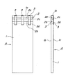
次に、断熱材の例について図を用いて説明する。図1は断熱材の構成を説明する図である。図2は図1の要部を拡大して説明する図である。 Next, an example of the heat insulating material will be described with reference to the drawings. Figure 1 is a diagram illustrating the configuration of the cross-sectional heated material. FIG. 2 is an enlarged view illustrating the main part of FIG.
図1,2に於いて、断熱材Aは、硬質の発泡板1の端面(発泡板1の長手方向の端面であって上部側の端面)1aに対して平行に、且つ発泡板1の両面1b,1cに夫々複数の溝2(2a〜2d)が設けられ、これらの溝2の少なくとも一部が覆シート3によって覆われて構成されている。
In FIGS. 1 and 2, the heat insulating material A is parallel to the end surface of the hard foam plate 1 (the end surface in the longitudinal direction of the foam plate 1 and the upper end surface) 1 a and both surfaces of the foam plate 1. A plurality of grooves 2 (2a to 2d) are provided in 1b and 1c, respectively, and at least a part of these
発泡板1は、フェノール樹脂発泡体からなる板によって構成されており、長さは建物の1層に於ける上下の梁の間に嵌め込まれたとき自己保持し得るように、上下の梁間の寸法よりも大きい寸法を有している。また幅は柱間の寸法に応じた寸法を有している。このフェノール樹脂発泡体は極めて高い断熱性を有するため、大きな厚さを必要としない。しかし、躯体を構成する上下の梁と左右方向の柱に配置されたときに特別な補強を施すことなく自立し得る程度の剛性を発揮することが可能な厚さ(例えば25mm)を有している。 The foam plate 1 is composed of a plate made of a phenol resin foam, and the length is a dimension between the upper and lower beams so that the length can be self-held when fitted between the upper and lower beams in one layer of the building. Larger dimensions. The width has a dimension corresponding to the dimension between the columns. Since this phenol resin foam has an extremely high heat insulating property, a large thickness is not required. However, it has a thickness (for example, 25 mm) capable of exhibiting rigidity to the extent that it can stand on its own without any special reinforcement when it is arranged on the upper and lower beams and the left and right columns constituting the frame. Yes.
複数の溝2は、発泡体1の厚さの半分よりも深い約15mm程度の深さを持って、且つ幅は約2mmの寸法を持って該発泡板1の幅方向の全長にわたって形成されている。特に本実施例では、発泡板1の両面1b,1cに夫々2条の溝2a,2b、溝2c,2dが形成されている。
The plurality of
覆シート3は、粘着性を持った幅が約50mm程度の紙テープを用いている。即ち、発泡板1がフェノール樹脂発泡体によって構成されているため、該発泡板1の両面1b,1cは不織布の面となり、粘着性を持った紙テープが良好な状態で貼着することが可能である。
The
覆シート3は、発泡板1の各面1b,1cに形成された溝2a,2b、溝2c,2dに対し直交する方向に配置され、二つの溝2a,2b及び溝2c,2cを同時に覆うようにして各面1b,1cに貼着されている。また覆シート3は各溝3a〜3dの長手方向(発泡板1の幅方向)に対し3個所を覆うように配置されている。
The
上記の如く構成された断熱材Aでは、溝2に対し直交する方向に発泡板1を圧縮させる力を作用させると、この力に応じて溝2(各溝2a〜2d)の幅が縮小することで断熱材Aの寸法が小さくなる。このとき、覆シート3は各溝2a〜2dを覆う部分に撓みが生じ、これにより、各溝2a〜2dの縮小を許容する。
In the heat insulating material A configured as described above, when a force for compressing the foam plate 1 is applied in a direction orthogonal to the
断熱材Aが縮小した状態を保持して該断熱材Aを目的の構成部材間に嵌め込み、その後、発泡板1を圧縮させる方向に作用する力を解除すると、この解除に伴って断熱材Aが元の寸法に復帰しようとし、端面1aが対抗する構成部材に圧接して自己保持する。従って、断熱材Aは、目的の配置部位に於ける柱や梁等の構成部材の間に於ける配置位置を安定した状態で確保することが可能となる。 When the heat insulating material A is held in a contracted state, the heat insulating material A is fitted between the target constituent members, and then the force acting in the direction of compressing the foamed plate 1 is released. An attempt is made to return to the original dimension, and the end surface 1a is pressed against the component member that the end face 1a opposes and self-holds. Therefore, the heat insulating material A can secure the arrangement position between the constituent members such as columns and beams in the target arrangement portion in a stable state.
また断熱材Aに例えば面1bから面1c方向への曲げ力が作用したとき、この曲げ力に応じて面1bに形成された溝2a,2bは開放部分が拡大し、面1cに形成された溝2c,2dは開放部分が縮小する。このとき、溝2a,2bの開放部分は一部が覆シート3に覆われて拘束されるため、過大な拡大が阻止され底部を起点とした破損が生じることがない。また溝2c,2dの開放部分は一部が覆シート3に覆われて拘束されるものの、該覆シート3が可撓性を有するため、溝2c,2dの開放部分の縮小に追従することが可能となる。
Further, when a bending force in the direction from the surface 1b to the surface 1c is applied to the heat insulating material A, for example, the
このように、断熱材Aに曲げ力が作用した場合であっても、溝2の底部を起点として破断することがなく、且つ構成部材の間に嵌め込まれて安定した状態を確保することが可能となる。
As described above, even when a bending force is applied to the heat insulating material A, it is possible to ensure a stable state by being fitted between the constituent members without being broken starting from the bottom of the
次に、断熱材Aを構成する発泡板1に設けた溝2を覆シート3によって覆う場合の覆い方の例について図を用いて説明する。図3は覆シートによって溝を覆う覆い方を説明する図である。
Next, the example of how to cover the groove |
図3(a)は、発泡板1の面1bに形成した二つの溝2a,2b、及び面1cに形成した二つの溝2c,2dに対し直交する方向の3個所に覆シート3を配置して覆った例である。この実施例では、各覆シート3は発泡板1の面1bから端面1aを跨いで面1c側に掛け渡され、各面1b,1cに形成された溝2a〜2dを一度に覆うように構成している。
In FIG. 3 (a), the
尚、発泡板1の材料が高い被粘着性を有するような場合には、覆シート3を発泡板1の端面1aから面1b側に形成された溝2a,2bに対して、また端面1aから面1cに形成された溝2c,2dに対して夫々配置して個別に覆うようにしても良い。
In the case where the material of the foam plate 1 has high adhesiveness, the
同図(b)は、発泡板1の面1bに形成された溝2a,2bに沿って2個所に覆シート3を配置して貼着することで各溝2a,2bの一部を覆うようにしたものである。この例では、覆シート3の幅寸法の如何に関わらず溝2a,2bに対する覆い寸法を設定することが可能となり、作業上の面や強度的な面で有利である。
In FIG. 2B, the
同図(c)は、発泡板1の面1bに形成された溝2a,2bを夫々全長にわたって覆シート3で覆うと共に、該覆シート3を面1bに貼着したものである。このように、溝2a,2bの端部を覆シート3によって覆うことで、欠けを含む破損のし易い部分を補強することが可能となり有利である。
FIG. 2C shows the
尚、溝2a,2bの全長を覆シート3によって覆うような場合、覆シート3として気密性を有する金属テープを用いることで、断熱材Aに気密性を発揮させることが可能となる。
In addition, when covering the full length of groove |
次に、鋼製梁の断熱気密構造の実施例について図を用いて説明する。図4は外壁に沿って断熱層を構成する際に鋼製梁の屋外側に断熱材を配置した構造を説明する図である。図5は鋼製梁に形成された穴を気密シートによって覆った状態を説明する図である。図6は鋼製梁の断熱気密構造を説明する断面図である。 Next, an embodiment of a heat insulating and airtight structure of steel beams will be described with reference to the drawings. FIG. 4 is a diagram illustrating a structure in which a heat insulating material is arranged on the outdoor side of a steel beam when a heat insulating layer is formed along the outer wall. FIG. 5 is a diagram for explaining a state where a hole formed in a steel beam is covered with an airtight sheet. FIG. 6 is a cross-sectional view illustrating a heat-insulating and air-tight structure of a steel beam.
先ず、図4により、建物の外壁に沿って構成された断熱層の構造について簡単に説明する。鋼製梁11は図示しない柱に支持されており、該柱の下端側は基礎梁或いは鋼製梁に接続されている。鋼製梁11の上部フランジ11aには上階の床12が支持されている。また鋼製梁11の屋外側には外壁13が構成されている。床12,外壁13の材料や構造は特に限定するものではないが、本実施例では軽量気泡コンクリートパネル(ALCパネル)を用いている。
First, with reference to FIG. 4, the structure of the heat insulating layer configured along the outer wall of the building will be briefly described. The steel beam 11 is supported by a column (not shown), and the lower end side of the column is connected to a foundation beam or a steel beam. An
鋼製梁11と下方に配置された図示しない基礎梁或いは鋼製梁との間に断熱材Aが配置されると共に、鋼製梁11の下部フランジ11bと下方の梁との間に嵌め込まれ、端面1aが下部フランジ11bに圧接して自己保持されている。 The heat insulating material A is disposed between the steel beam 11 and a base beam or steel beam (not shown) disposed below, and is fitted between the lower flange 11b of the steel beam 11 and the lower beam, The end surface 1a is pressed against the lower flange 11b and is self-held.
また鋼製梁11のウエブ11cには気密シート14が配置されており、この気密シート14によって該ウエブ11cに形成された穴11d,11eが覆われている。更に、鋼製梁11のウエブ11cの屋外側には断熱材Bが配置されると共に、上下のフランジ11a,11bの間に嵌め込まれて自己保持されている。
An
このように、鋼製梁11の屋外側には略同一面上に断熱材A,Bが配置されることとなり、これらの断熱材A,Bによって断熱層が構成されている。 As described above, the heat insulating materials A and B are arranged on substantially the same surface on the outdoor side of the steel beam 11, and the heat insulating layers are constituted by these heat insulating materials A and B.
次に、図5,6により鋼製梁の断熱気密構造についてより詳しく説明する。尚、図に於いて、前述の断熱材Aと同一の部分及び同一の機能を有する部分には同一の符号を付して説明を省略する。 Next, the heat insulating and airtight structure of the steel beam will be described in more detail with reference to FIGS. It should be noted that, in FIG, its description is omitted with the same reference numerals with a cross-sectional thermal material A same parts and the same function as described above.
図5に示すように、鋼製梁11のウエブ11cには一定の間隔で配管や配線を通す比較的径の大きい穴11dと、ウエブ11cに他の部材(例えば鋼製梁)を取り付けるために用いるボルトを通す比較的径の小さい穴11eが形成されている。また図6に示すように上部フランジ11aには該上部フランジ11aに他の部材(例えば上階の柱等)を取り付けるためのボルトを通す穴11fが形成されている。 As shown in FIG. 5, the web 11c of the steel beam 11 has a relatively large diameter hole 11d through which piping and wiring are passed at regular intervals, and other members (for example, steel beams) are attached to the web 11c. A relatively small hole 11e through which the bolt to be used is passed is formed. As shown in FIG. 6, the upper flange 11a is formed with a hole 11f through which a bolt for attaching another member (for example, an upper floor pillar) is attached to the upper flange 11a.
本実施例では、鋼性梁11のウエブ11cに形成された複数の穴11d,11eを気密シート14によって気密性を確保している。気密シート14によって穴11d,11eを覆う際に、気密シート14をウエブ11cに密着させると共にこの密着状態を保持する方法については特に限定するものではない。
In this embodiment, a plurality of holes 11 d and 11 e formed in the web 11 c of the steel beam 11 are secured by the
本実施例では、気密シート14として透明な合成樹脂製でウエブ11cに対する粘着性を持ったシートを用いている。従って、気密シート14を鋼製梁11のウエブ11cに貼着することで、穴11d,11eの全てを覆うことが可能である。
In this embodiment, a sheet made of a transparent synthetic resin and having adhesiveness to the web 11c is used as the
特に、気密シート14をウエブ11cの両面に貼着した場合には、気密シート14の粘着層が穴11d,11eから露出した状態で長期間保持するようなことがなく、しかも穴11d,11eの二つの開口部分が気密シート14によって覆われることで、高い気密性を確保することが可能となる。
In particular, when the
断熱材Bは、高さ寸法が鋼製梁11の上下フランジ11a,11bの対向する面間の寸法よりも大きく形成され、高さ方向の両端面1a,1d側に、夫々端面1a,1dと平行に且つ両面1b,1cに複数の溝2が形成されており、各溝2は覆シート3によって一部が覆われている。
The heat insulating material B is formed so that the height dimension is larger than the dimension between the opposing surfaces of the upper and lower flanges 11a, 11b of the steel beam 11, and the end faces 1a, 1d and the end faces 1a, 1d, respectively. A plurality of
また発泡板1の端面1aには、該発泡板1の厚さ方向の略中央に予め設定された幅寸法と深さ寸法を持った凹溝1eが形成されており、この凹溝1eによって鋼製梁11の上部フランジ11aに形成された穴11fにボルトを通したとき、上部フランジ11aの下側の面に配置されるボルトの頭部を回避し得るように構成されている。 Further, the end surface 1a of the foam plate 1 is formed with a concave groove 1e having a preset width dimension and depth dimension at substantially the center in the thickness direction of the foam plate 1. When a bolt is passed through a hole 11f formed in the upper flange 11a of the beam 11, the bolt head arranged on the lower surface of the upper flange 11a can be avoided.
本実施例に於いて、断熱材Bには幅寸法が約2mmの溝が全部で8条形成されており、高さ方向に圧縮力を作用させたとき、該断熱材Bを約10mm〜14mm程度圧縮することが可能である。この圧縮寸法は、予め鋼製梁11の上部フランジ11aに形成した穴11fにボルトを締結した場合でも、このボルトの頭部を容易に回避し得る寸法である。 In this example, the heat insulating material B is formed with a total of 8 grooves having a width of about 2 mm, and when a compressive force is applied in the height direction, the heat insulating material B is about 10 mm to 14 mm. It is possible to compress to some extent. This compression dimension is a dimension that can easily avoid the head of the bolt even when the bolt is fastened to the hole 11f formed in the upper flange 11a of the steel beam 11 in advance.
上記の如く、予め鋼製梁11のウエブ11cに形成された穴11d,11eを気密シート14によって覆っておき、その後、断熱材Bに対し高さ方向の圧縮力を作用させて各溝2を縮小させることで収縮させる。次いで、端面1dを鋼製梁11の下部フランジ11bの上面に当接させた状態で、端面1aを上部フランジ11aの端部側から下面側に移動させて対向させる。この過程で、上部フランジ11aに形成された穴11fに通されているボルトの頭部を回避する。
As described above, the holes 11d and 11e formed in the web 11c of the steel beam 11 in advance are covered with the
そして断熱材Bに対する圧縮を解除すると、縮小している各溝2が元の状態に復帰しようとし、このときの復元力によって、端面1aが上部フランジ11aの下面に圧接すると共に端面1dが下部フランジ11bの上面に圧接してこの状態を保持する。
When the compression of the heat insulating material B is released, each shrinking
従って、鋼製梁11は、ウエブ11cの屋外側が断熱材Bによって断熱され、ウエブ11cに形成された穴11d,11eが気密シート14によって覆われることで気密性が確保されることになる。
Therefore, the steel beam 11 is heat-insulated by the outdoor side of the web 11c being insulated by the heat insulating material B and the holes 11d and 11e formed in the web 11c being covered by the air-
上記の如く構成された鋼製梁の断熱気密構造では、鋼製梁11の長手方向に沿って複数の断熱材Bを連続した配置した場合であっても、各断熱材Bの接続部位に於ける気密性を確保しなくとも、ウエブ11cに形成された穴11d,11eが気密シート14によって覆われていることで気密性を確保することが可能である。
In the heat-insulating and air-tight structure of steel beams configured as described above, even when a plurality of heat insulating materials B are continuously arranged along the longitudinal direction of the steel beams 11, the connection portions of the heat insulating materials B are connected. Even if the airtightness is not secured, the holes 11d and 11e formed in the web 11c are covered with the
本発明の鋼製梁の断熱気密構造では、鋼製梁の屋外側に断熱材を配置して自己保持することが可能となり、且つ鋼製梁のウエブに形成された穴を気密シートによって覆うことで高い気密性を発揮させることが可能となる。このため、外壁に沿って略同一面内に断熱層を構成することが可能となり有利である。 In the heat-insulating and air-tight structure of the steel beam of the present invention, it is possible to place a heat insulating material on the outdoor side of the steel beam to self-hold, and to cover the hole formed in the steel beam web with an air-tight sheet. It is possible to exhibit high airtightness. For this reason, it becomes possible to constitute a heat insulation layer in substantially the same plane along the outer wall, which is advantageous.
A,B 断熱材
1 発泡板
1a,1d 端面
1b,1c 面
1e 凹溝
2,2a〜2d 溝
3 覆シート
11 鋼製梁
11a 上部フランジ
11b 下部フランジ
11c ウエブ
11d〜11f 穴
12 床
13 外壁
14 気密シート
A, B Heat insulating material 1 Foam plate 1a, 1d End surface 1b, 1c
Claims (1)
Priority Applications (1)
| Application Number | Priority Date | Filing Date | Title |
|---|---|---|---|
| JP2005181706A JP4849833B2 (en) | 2005-06-22 | 2005-06-22 | Insulated and airtight structure of steel beams |
Applications Claiming Priority (1)
| Application Number | Priority Date | Filing Date | Title |
|---|---|---|---|
| JP2005181706A JP4849833B2 (en) | 2005-06-22 | 2005-06-22 | Insulated and airtight structure of steel beams |
Publications (2)
| Publication Number | Publication Date |
|---|---|
| JP2007002454A JP2007002454A (en) | 2007-01-11 |
| JP4849833B2 true JP4849833B2 (en) | 2012-01-11 |
Family
ID=37688315
Family Applications (1)
| Application Number | Title | Priority Date | Filing Date |
|---|---|---|---|
| JP2005181706A Active JP4849833B2 (en) | 2005-06-22 | 2005-06-22 | Insulated and airtight structure of steel beams |
Country Status (1)
| Country | Link |
|---|---|
| JP (1) | JP4849833B2 (en) |
Families Citing this family (1)
| Publication number | Priority date | Publication date | Assignee | Title |
|---|---|---|---|---|
| JP4891442B1 (en) * | 2011-02-18 | 2012-03-07 | 健一 佐藤 | Board panel |
Family Cites Families (5)
| Publication number | Priority date | Publication date | Assignee | Title |
|---|---|---|---|---|
| JPS60184903A (en) * | 1984-03-05 | 1985-09-20 | Hitachi Ltd | Steam turbine rotor |
| JPH03113007A (en) * | 1989-09-25 | 1991-05-14 | Kosei Hata | Collection of chained and arranged flax fiber |
| JPH1061053A (en) * | 1996-08-26 | 1998-03-03 | Matsushita Electric Works Ltd | Composite beam |
| JP3901316B2 (en) * | 1997-12-08 | 2007-04-04 | 旭化成ホームズ株式会社 | H-shaped steel insulation method and insulation structure |
| JP3821289B2 (en) * | 2002-09-03 | 2006-09-13 | 積水ハウス株式会社 | Airtight structure at the connecting corner of the beam |
-
2005
- 2005-06-22 JP JP2005181706A patent/JP4849833B2/en active Active
Also Published As
| Publication number | Publication date |
|---|---|
| JP2007002454A (en) | 2007-01-11 |
Similar Documents
| Publication | Publication Date | Title |
|---|---|---|
| US20100095625A1 (en) | Rigid foam insulating panel with compressible joint | |
| JP4849833B2 (en) | Insulated and airtight structure of steel beams | |
| EP1360382B1 (en) | Building panel having at least two panel domains of different average compressive strength | |
| JP4001524B2 (en) | Hermetic structure and method for forming hermetic structure | |
| JP4969857B2 (en) | Breathable spacer | |
| JP4017462B2 (en) | Thermal insulation structure of outer wall | |
| JP4878765B2 (en) | Hermetic structure and composite hermetic insulation and elastic foam | |
| KR101922940B1 (en) | Molding system using quasi-noncombustible heat insulator and construction method therefor | |
| JP4017473B2 (en) | Insulation filling structure and filling method | |
| JP2018025058A (en) | Heat insulation material, wall unit, construction method for heat insulation wall and house | |
| JP2007239218A (en) | Floor heat insulation structure | |
| JP2007262850A (en) | Thermal insulation panel for roof and roof structure | |
| JP3966785B2 (en) | Book wall structure and insulation construction method | |
| JP2008180017A (en) | Floor substrate structure and method of constructing the same | |
| JP2006052590A (en) | Heat insulation panel used in common for form and heat insulation concrete skeleton structure using the same and its construction method | |
| JP3183566U (en) | Drainage material with backup material and waterproof structure of side joint | |
| JPH02304141A (en) | Joint gasket | |
| JP4827901B2 (en) | Ceiling insulation structure | |
| JP2004218423A (en) | Opening structure of exterior wall | |
| JP6598197B2 (en) | Architectural panels and interior wall structures | |
| JP2004076314A (en) | Airtight structure of residence | |
| JP2016151640A (en) | Soundproof material | |
| JP2816952B2 (en) | Architectural panel and outer wall structure of building using the same | |
| JP2003027619A (en) | Beam structure of steel-framed house, and steel-framed house | |
| JP4043316B2 (en) | Airtight substrate structure at the joint |
Legal Events
| Date | Code | Title | Description |
|---|---|---|---|
| RD02 | Notification of acceptance of power of attorney |
Free format text: JAPANESE INTERMEDIATE CODE: A7422 Effective date: 20080131 |
|
| A621 | Written request for application examination |
Free format text: JAPANESE INTERMEDIATE CODE: A621 Effective date: 20080529 |
|
| A977 | Report on retrieval |
Free format text: JAPANESE INTERMEDIATE CODE: A971007 Effective date: 20101209 |
|
| A131 | Notification of reasons for refusal |
Free format text: JAPANESE INTERMEDIATE CODE: A131 Effective date: 20101221 |
|
| A521 | Written amendment |
Free format text: JAPANESE INTERMEDIATE CODE: A523 Effective date: 20110218 |
|
| A131 | Notification of reasons for refusal |
Free format text: JAPANESE INTERMEDIATE CODE: A131 Effective date: 20110524 |
|
| A521 | Written amendment |
Free format text: JAPANESE INTERMEDIATE CODE: A523 Effective date: 20110704 |
|
| TRDD | Decision of grant or rejection written | ||
| A01 | Written decision to grant a patent or to grant a registration (utility model) |
Free format text: JAPANESE INTERMEDIATE CODE: A01 Effective date: 20111018 |
|
| A01 | Written decision to grant a patent or to grant a registration (utility model) |
Free format text: JAPANESE INTERMEDIATE CODE: A01 |
|
| A61 | First payment of annual fees (during grant procedure) |
Free format text: JAPANESE INTERMEDIATE CODE: A61 Effective date: 20111018 |
|
| R150 | Certificate of patent or registration of utility model |
Ref document number: 4849833 Country of ref document: JP Free format text: JAPANESE INTERMEDIATE CODE: R150 Free format text: JAPANESE INTERMEDIATE CODE: R150 |
|
| FPAY | Renewal fee payment (event date is renewal date of database) |
Free format text: PAYMENT UNTIL: 20141028 Year of fee payment: 3 |
|
| S531 | Written request for registration of change of domicile |
Free format text: JAPANESE INTERMEDIATE CODE: R313531 |
|
| R350 | Written notification of registration of transfer |
Free format text: JAPANESE INTERMEDIATE CODE: R350 |