JP4847983B2 - Body front structure - Google Patents
Body front structure Download PDFInfo
- Publication number
- JP4847983B2 JP4847983B2 JP2008137451A JP2008137451A JP4847983B2 JP 4847983 B2 JP4847983 B2 JP 4847983B2 JP 2008137451 A JP2008137451 A JP 2008137451A JP 2008137451 A JP2008137451 A JP 2008137451A JP 4847983 B2 JP4847983 B2 JP 4847983B2
- Authority
- JP
- Japan
- Prior art keywords
- vehicle
- hood
- cross
- central portion
- central
- Prior art date
- Legal status (The legal status is an assumption and is not a legal conclusion. Google has not performed a legal analysis and makes no representation as to the accuracy of the status listed.)
- Expired - Fee Related
Links
Images


Description
本発明は、車両の正面に配置されているバルクヘッドアッパメンバを備えた車体前部構造に関するものである。 The present invention relates to a vehicle body front structure provided with a bulkhead upper member disposed in front of a vehicle.
車体前部構造には、例えば、車両前方側からアッパメンバに衝突力が作用したときに、ラジエータとアッパメンバとが一体的に変形するのではなく、アッパメンバがラジエータに比べて優先的に変形するので、障害物(例えば、歩行者)からの衝突力に対する曲げ剛性が小さくなり、障害物(歩行者)の保護を図ることができるというものが知られている(例えば、特許文献1参照。)。
しかし、特許文献1の車両の前端構造では、アッパメンバ(バルクヘッドアッパメンバ
)の上方に開閉自在に設けたフードを開閉させたときの支持剛性を得るために、アッパメンバの中央から下方にセンターブレース(支柱)を垂下し下方のロアメンバに支持する必要があり、センターブレースによって部品数が増加し、ラジエータの配置の自由度が減少するという問題がある。
However, in the vehicle front end structure disclosed in Patent Document 1, in order to obtain support rigidity when the hood provided to be freely opened and closed above the upper member (bulkhead upper member) is obtained, a center brace ( There is a problem in that the number of parts is increased by the center brace, and the degree of freedom in arranging the radiator is reduced.
本発明は、車両の正面に障害物から加わる荷重に対して、バルクヘッドアッパメンバの衝撃吸収の向上を図り、バルクヘッドアッパメンバの中央を下方に支持する支柱を用いることなく、バルクヘッドアッパメンバの強度を確保し、フードを支持する強度を確保し、フードロック装置の配置の自由度を高めた車体前部構造を提供することを課題とする。 The present invention improves the impact absorption of the bulkhead upper member against a load applied from an obstacle to the front of the vehicle, and does not use a column that supports the center of the bulkhead upper member downward. It is an object of the present invention to provide a vehicle body front structure that secures the strength of the hood, secures the strength to support the hood, and increases the degree of freedom of arrangement of the hood lock device.
請求項1に係る発明は、車室の前に連なるフロントボデーの上部に開閉自在に設けたフードのフード前部の下方に、車両の左右に延ばしたバルクヘッドアッパメンバが配置されている車体前部構造において、バルクヘッドアッパメンバは、平面視で、長さに対する中央に形成された中央部が車両の前方に向かう凹凸のない平坦に形成されているとともに中央部を断面閉構造とし、左端部及び右端部をそれぞれ断面閉構造とし、左端部と中央部との間の左緩衝部を開断面構造とし、右端部と中央部との間の右緩衝部を開断面構造とし、中央部の平坦の前にフード前部をロックするフードロック装置のフードロックブラケットを配置し、左緩衝部及び右緩衝部に対して、中央部を車両の後方へオフセットし、フードロックブラケットにフードロック装置を取付けるために設けた左右の凸部の頂部を中央部の平坦に形成されている平坦部から車両の前方へオフセットし、中央部の断面閉構造は、断面U字状の溝形部材の開口を下方へ向けて配置し、溝形部材の開口に中央板部材を取付けることで形成され、左端部及び右端部の断面閉構造は、溝形部材の開口に左板部材、右板部材をそれぞれ取付けることで形成されていることを特徴とする。 According to the first aspect of the present invention, a bulkhead upper member extending to the left and right of a vehicle is disposed below a hood front portion of a hood that is openable and closable at an upper portion of a front body that is connected to the front of a vehicle compartment. In the partial structure, the bulkhead upper member has a central portion formed in the center with respect to the length in a plan view, is formed flat without an unevenness toward the front of the vehicle, and the central portion has a cross-sectional closed structure, and the left end portion The right end portion has a closed cross section structure, the left buffer portion between the left end portion and the central portion has an open cross section structure, the right buffer portion between the right end portion and the central portion has an open cross section structure, and the center portion is flat. place the hood lock bracket of the hood lock device for locking the hood front in front of, the left buffer unit and the right buffer unit, it offsets the central portion to the rear of the vehicle, Fudoro' the hood lock bracket The tops of the left and right convex portions provided for mounting the device are offset from the flat portion formed flat at the central portion to the front of the vehicle, and the cross-sectional closed structure at the central portion is a groove-shaped member having a U-shaped cross section. It is formed by arranging the opening downward and attaching the central plate member to the opening of the groove member. The cross-sectional closed structure of the left end portion and the right end portion includes the left plate member and the right plate member in the opening of the groove member. It is formed by attaching each .
請求項1に係る発明では、車体前部構造のバルクヘッドアッパメンバは、平面視で、長さに対する中央に形成された中央部が車両の前方に向かう凹凸のない平坦に形成されているとともに中央部を断面閉構造とし、左端部及び右端部をそれぞれ断面閉構造とし、中央部に連ねた左緩衝部を開断面構造とし、中央部に連ねた右緩衝部を開断面構造とし、中央部の平坦の前にフードロックブラケットを配置し、左緩衝部及び右緩衝部に対して、中央部を車両の後方へオフセットし、フードロックブラケットにフードロック装置を取付けるために設けた左右の凸部の頂部を中央部の平坦に形成されている平坦部から車両の前方へオフセットし、中央部の断面閉構造は、断面U字状の溝形部材の開口を下方へ向けて配置し、溝形部材の開口に中央板部材を取付けることで形成され、左端部及び右端部の断面閉構造は、溝形部材の開口に左板部材、右板部材をそれぞれ取付けることで形成されているので、車両の正面に障害物から荷重が加わると、正面に位置しているバルクヘッドアッパメンバが変形し始め、最初に、開断面構造とした左緩衝部及び右緩衝部が、たわんで変形するとともに、前方へオフセットした凸部の頂部によって荷重の入力位置が偏心するためモーメントが発生し、ねじれて荷重を吸収する。従って、障害物から加わる荷重に対するバルクヘッドアッパメンバの衝撃吸収の向上を図ることができる。 In the invention according to claim 1, the bulkhead upper member of the vehicle body front structure has a central portion formed at the center with respect to the length in a plan view and is formed flat without any irregularities toward the front of the vehicle. The section has a closed cross-section structure, the left end and the right end section each have a closed cross-section structure, the left buffer section connected to the center section has an open section structure, the right buffer section connected to the center section has an open section structure, Place the hood lock bracket in front of the flat , offset the center part to the rear of the vehicle with respect to the left buffer part and right buffer part, and the left and right convex parts provided to attach the hood lock device to the hood lock bracket The top portion is offset from the flat portion formed flat at the center portion to the front of the vehicle, and the cross-section closed structure at the center portion is arranged such that the opening of the groove-shaped member having a U-shaped section is directed downward. Center plate at the opening of It is formed by attaching a sectional closed structure at the left end and the right end, Hidariban member into the opening of the channel members, since the right plate member are formed by attaching each load from the obstacle in front of the vehicle The bulkhead upper member located at the front begins to deform, and the left shock absorbing part and the right shock absorbing part having an open cross-sectional structure are bent and deformed , and the top of the convex part offset forward As a result, the input position of the load is decentered to generate a moment, which twists and absorbs the load. Therefore, it is possible to improve the impact absorption of the bulkhead upper member with respect to the load applied from the obstacle.
また、車体前部構造では、中央部が車両の前方に向かう凹凸のない平坦に形成され、平坦の前にフードロックブラケットを配置した。すなわち、フードロックブラケットを別部材として配置することで、中央部を凹凸のない平坦に形成することができ、左右の凸部からフードロックブラケットを介して中央部に分散し、応力集中が起きず、強度を高めることができる。バルクヘッドアッパメンバの中央を下方に支持する支柱を用いることなく、バルクヘッドアッパメンバの強度を確保することができる。 Moreover, in the vehicle body front part structure, the central part is formed flat without unevenness toward the front of the vehicle, and the hood lock bracket is disposed in front of the flat. In other words, by arranging the hood lock bracket as a separate member, the central portion can be formed flat without unevenness, and the right and left convex portions are distributed to the central portion via the hood lock bracket, and stress concentration does not occur. , Can increase the strength. The strength of the bulkhead upper member can be ensured without using a column that supports the center of the bulkhead upper member downward.
さらに、車体前部構造では、中央部が車両の前方に向かう凹凸のない平坦に形成されているとともに中央部を断面閉構造としたので、衝撃を吸収する左緩衝部及び右緩衝部をバルクヘッドアッパメンバに設けても、バルクヘッドアッパメンバの中央を下方に支持する支柱を用いることなく、フードを支持する強度を確保することができる。 Furthermore, in the vehicle body front structure, the central portion is formed flat without unevenness toward the front of the vehicle, and the central portion has a closed cross-section structure, so the left shock absorbing portion and the right shock absorbing portion that absorb impact are bulkheads. Even if it is provided on the upper member, the strength for supporting the hood can be ensured without using a column that supports the center of the bulkhead upper member downward.
その上、車体前部構造では、中央部が車両の前方に向かう凹凸のない平坦に形成され、平坦の前にフードロックブラケットを配置したので、フードロックブラケットの配置の自由度が高まり、車両の前方、後方に対するフードロック装置の配置の自由度を高めることができる。 In addition, in the vehicle body front structure, the central portion is formed flat without unevenness toward the front of the vehicle, and the hood lock bracket is arranged in front of the flat, so the degree of freedom of arrangement of the hood lock bracket is increased, and the vehicle The freedom degree of arrangement | positioning of the food lock apparatus with respect to the front and back can be raised.
請求項1に係る発明では、左緩衝部及び右緩衝部に対して、中央部を車両の後方へオフセットし、フードロックブラケットを車両の前方へオフセットしているので、中央部の設計の自由度が高まり、中央部を平坦にすることができる。
また、オフセットによって、フードロックブラケットの設計の自由度が高まり、車両の前方、後方に対するフードロック装置の配置の自由度をより高めることができる。
In the invention according to claim 1 , since the center part is offset to the rear of the vehicle and the hood lock bracket is offset to the front of the vehicle with respect to the left buffer part and the right buffer part, the degree of freedom in designing the center part And the central part can be flattened.
In addition, the degree of freedom in designing the hood lock bracket is increased by the offset, and the degree of freedom in arranging the hood lock device with respect to the front and rear of the vehicle can be further increased.
本発明を実施するための最良の形態を添付図に基づいて以下に説明する。
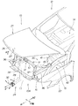
図1は、本発明の車体前部構造を含む車両のフロント部の分解図である。
車体前部構造11は、車両12のフロント部13に採用され、車室14の前に連なるフロントボデー15のフロント前部16に含まれるバルクヘッドアッパメンバ17を備える。具体的には後述する。
The best mode for carrying out the present invention will be described below with reference to the accompanying drawings.
FIG. 1 is an exploded view of a front portion of a vehicle including a vehicle body front portion structure of the present invention.
The vehicle
フロント部13は、フロントボデー15に開閉自在(矢印a1の方向)に取付けられ、図に示していないエンジンなどの機器をカバーしているフード21と、フロントボデー15の左右に取付けられているフロントフェンダ22と、フード21を閉じた状態に保ちロックするフードロック装置24と、を備える。
The
フードロック装置24は、フード21のフード前部26にU字形のストライカ27が取付けられ、ストライカ27を係止するロック機構28がバルクヘッドアッパメンバ17にフードロックブラケット31を介して取付けられ、ロック機構28にオープナケーブル32が接続され、オープナケーブル32に接続したオープナノブ(図に示していない)が車室14に配置されている。
ロック機構28は、既存の構成である。
In the
The
フロントボデー15は、エンジンルーム35と、エンジンルーム35の左右のフロントサイドフレーム36と、フロントサイドフレーム36の前に連なる左右のフロントサイドバルクヘッド37と、フロントサイドバルクヘッド37の下端同士を接続しているフロントロアクロスメンバ38と、フロントサイドフレーム36から上へ連なる左右のダンパハウジング41と、ダンパハウジング41の上部に連なるホイールハウスアッパメンバ42と、ホイールハウスアッパメンバ42の前に連なるバルクヘッドアッパメンバ17と、を備える。
なお、車体前部構造11を主体にすると、車体前部構造11は、バルクヘッドアッパメンバ17を含む。
The
When the vehicle
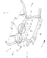
図2は、本発明の車体前部構造の斜視図である。図1を併用して説明する。
車体前部構造11は、具体的には、バルクヘッドアッパメンバ17と、フロントサイドバルクヘッド37と、フロントロアクロスメンバ38と、フードロックブラケット31と、を備えている。
FIG. 2 is a perspective view of the front body structure of the present invention. This will be described with reference to FIG.
Specifically, the vehicle body
バルクヘッドアッパメンバ17はホイールハウスアッパメンバ42に連なる左アッパメンバ45と、右アッパメンバ46と、これらに連なり中央に配置されている中央アッパメンバ47と、からなり、車両12の車幅方向(X軸方向)の中心Cを基準に左右がほぼ対称で、中央アッパメンバ47が本発明の車体前部構造11の主体をなしている。
The bulkhead
中央アッパメンバ47は、車両12の車幅方向(X軸方向)の中央に配置している中央部51と、左に順に形成した左緩衝部52と、左端部53と、右に順に形成した右緩衝部54と、右端部55と、フードロックブラケット31と、からなる。
The central
図3は、図2の3−3矢視図である。本発明の車体前部構造が備えるバルクヘッドアッパメンバ(中央アッパメンバ47)の平面を示している。図1を併用して説明する。 FIG. 3 is a view taken along arrow 3-3 in FIG. The plane of the bulkhead upper member (center upper member 47) with which the vehicle body front part structure of the present invention is provided is shown. This will be described with reference to FIG.
中央アッパメンバ47は、平面視(図3及び図4の視点)で、長さ(X軸方向)に対する中央に形成された中央部51が車両12の前方(矢印a1の方向)に向かう凹凸のない平坦に形成されているとともに中央部51を断面閉構造とし、左端部53及び右端部55をそれぞれ断面閉構造とし、左端部53と中央部51との間の左緩衝部52を開断面構造とし、右端部55と中央部51との間の右緩衝部54を開断面構造とし、中央部51にフード前部26をロックするフードロック装置24のフードロックブラケット31を配置している。
The central
「車両12の前方に向かう凹凸」とは、フードロックブラケット31の第1凸部57、第2凸部58に相当する部位である。
“Unevenness toward the front of the
断面閉構造は、長尺な上板溝形部材61に下板部材62が取付けられた部位で、下板部材62は中央下板L形部材63、左下板溝形部材64、右下板溝形部材65からなる。
The closed cross-sectional structure is a portion where a
また、中央アッパメンバ47は、左緩衝部52及び右緩衝部54に対して、中央部51を車両12の後方(矢印a2の方向)へ距離Erだけオフセットし、フードロックブラケット31を車両12の前方へ距離Efだけオフセットしている。
Further, the central
図4は、バルクヘッドアッパメンバの平面図である。フードロックブラケット31を取り外した状態の中央部51を示している。
中央部51は、上板溝形部材61の上板前壁部67が平坦になっている。詳しくは、中央部51に対応する上板前壁部67には、平坦部68が形成されている。
FIG. 4 is a plan view of the bulkhead upper member. The
In the
図5は、バルクヘッドアッパメンバの断面閉構造に用いられた下板部材の平面図である。図3、図4を併用して説明する。
下板部材62は、中央下板L形部材63、左下板溝形部材64、右下板溝形部材65からなる。
断面閉構造では、上板溝形部材61に短い中央下板L形部材63を取付けることで中央部51が形成され、上板溝形部材61に短い左下板溝形部材64を取付けることで左端部53が形成され、上板溝形部材61に短い右下板溝形部材65を取付けることで右端部55が形成されている。
左緩衝部52、右緩衝部54が上板溝形部材61のみで形成されている。
FIG. 5 is a plan view of the lower plate member used for the cross-sectional closed structure of the bulkhead upper member. This will be described with reference to FIGS.
The
In the closed cross-section structure, a
The
図6は、図2の6部詳細図である。上板溝形部材61や右端部55の詳細を一部破断にして示している。図3、図5を併用して説明する。
上板溝形部材61は、断面U字状で、上板溝開口71を下方へ向けて配置し、車両12の前方(矢印a1の方向)へ向いている上板前壁部67を形成し、連ねて上板天部72、上板後壁部73を形成したものである。そして、右端部55に対応する上板前壁部67の縁に連ねて右上板フランジ部74が形成され、右緩衝部54に対応する上板前壁部67の縁に連ねて右緩衝フランジ部75が形成されている。
FIG. 6 is a detailed view of
The upper plate groove-shaped
右緩衝フランジ部75は前方から(矢印a5の方向)の荷重に対する右緩衝部54の強度確保に寄与している。
The right shock-absorbing
右端部55は、前述の上板溝開口71に右下板溝形部材65を取付けることで上板溝開口71を閉じた部位で、閉断面構造である。
右下板溝形部材65は、断面U字状で、下板溝開口81を下方へ向けて配置し、車両12の前方へ向いている下板前壁部82を形成し、連ねて下板天部83、下板後壁部84を形成している。右端部55に対応する下板前壁部82の縁に連ねて右下板フランジ部85が形成されている。
The
The right lower plate groove-shaped
また、上板溝形部材61に下板前壁部82、右下板フランジ部85、下板後壁部84が、例えば、スポット溶接の溶接部で接合されている。
右下板フランジ部85及び右上板フランジ部74は、右緩衝フランジ部75より大きく、より右端部55の強度を高めている。
Further, the lower plate
The lower right
左端部53は、右端部55と同様(対称)である。
左下板溝形部材64は、右下板溝形部材65と同様(対称)である。
The
The lower left
右緩衝部54は、既に述べた断面U字状で、上板溝開口71を残した部位である。左緩衝部52は、右緩衝部54と同様(対称)である。その結果、上板溝形部材61をプレス成形した時点で、形成されるので、右緩衝部54及び左緩衝部52の製造は容易である。
The
図7は、図2の7部詳細図である。中央部51やフードロックブラケット31の詳細を一部破断にして示している。
図8は、図7の8−8線断面図である。図4を併用して説明する。
FIG. 7 is a detailed view of
8 is a cross-sectional view taken along line 8-8 in FIG. This will be described with reference to FIG.
中央部51は、上板前壁部67に平坦部68が形成されている。
そして、前述の上板溝開口71に中央下板L形部材63を取付けることで上板溝開口71を閉じた閉断面構造としている。
さらに、中央部51に対応する上板後壁部73の縁に連ねて中央上板フランジ部87が形成されている。
中央上板フランジ部87は、車両12の前方から(矢印a5の方向)加わる荷重に対する中央部51の強度をより高めることができる。
In the
Then, a closed cross-sectional structure in which the upper
Further, a central upper
The center upper
中央下板L形部材63は、断面L字形で、上板溝開口71を閉じている下板中央本体部88を形成し、下板中央本体部88に連ね上板前壁部67に、スポット溶接の溶接部91で接合されている下板中央前部92を形成している。
The central lower plate L-shaped
フードロックブラケット31は、上板溝形部材61の上板天部72にスポット溶接の溶接部94で取付けられている第1取付け部95が形成され、第1取付け部95に連ねほぼ直交している第2取付け部96が形成されて上板前壁部67にスポット溶接の溶接部97で接合し、第2取付け部96にはロック機構28を取り付ける第1凸部57、第2凸部58が形成されている。第1凸部57及び第2凸部58の頂部101に締結用のナット102を溶接にて取付けた。
The
次に、本発明の車体前部構造の作用を説明する。図1〜図8を併用して説明する。
図9は、本発明の車体前部構造の衝撃吸収の機構を説明する図である。
車体前部構造11は、車両12の正面104に荷重Fが加わると、バルクヘッドアッパメンバ17の左緩衝部52及び右緩衝部54が矢印b1のように、たわんで変形するので、障害物105からの衝撃を吸収することができる。
障害物105が歩行者の場合、歩行者の受ける衝撃を低減することができる。
Next, the operation of the vehicle body front structure of the present invention will be described. 1 to 8 will be used together for explanation.
FIG. 9 is a diagram for explaining the shock absorbing mechanism of the vehicle body front structure according to the present invention.
When a load F is applied to the
When the
具体的には、障害物105に車両12の正面104が接触して、障害物105がフード21側に倒れ込み、障害物105の上部がフード21を変形させつつ、バルクヘッドアッパメンバ17の中央アッパメンバ47に荷重が伝わると、図6〜図8の下板部材62(中央下板L形部材63、左下板溝形部材64、右下板溝形部材65)のない開断面構造とした左緩衝部52及び右緩衝部54のそれぞれが前方へ(矢印b2の方向)回転(ねじれ)しながら下方へ変位して、中央部51が下がる((矢印b3の方向))。従って、歩行者など障害物105の受ける衝撃を低減することができる。
Specifically, the
また、車体前部構造11は、図7、図8のフードロックブラケット31を別部材とし、フードロック装置24のロック機構28の取付けに必要な第1凸部57、第2凸部58をフードロックブラケット31に形成したので、上板前壁部67に平坦部68を形成して、平坦にすることができる。その結果、上板前壁部67に一体に第1凸部57、第2凸部58のような凹凸を形成した場合に比べ、応力集中が起きず、強度を高めることができる。従って、閉断面構造に比べて小さな荷重で変形する左緩衝部52及び右緩衝部54を設けたにもかかわらず、バルクヘッドアッパメンバ17の強度を確保することができる。
Further, the vehicle
さらに、車体前部構造11は、図1、図7、図8のフードロック装置24を取付ける中央部51を断面U字状の上板溝形部材61に中央下板L形部材63を取付けることで形成した閉断面構造としたので、閉断面構造に比べて小さな荷重で変形する左緩衝部52及び右緩衝部54を設けたにもかかわらず、フード21を支持する強度を確保することができる。
Further, the vehicle
バルクヘッドアッパメンバ17は、図3に示した左緩衝部52及び右緩衝部54に対して、中央部51を車両12の後方(矢印a2の方向)へ距離Erだけオフセットし、フードロックブラケット31を車両12の前方へ距離Efだけオフセットしているので、中央部51の設計の自由度が高まり、中央部51を平坦にすることができる。
また、オフセットによって、フードロックブラケット31の設計の自由度が高まり、車両12の前方、後方に対するフードロック装置24の配置の自由度を高めることができる。
The bulkhead
Moreover, the freedom degree of design of the
尚、本発明の車体前部構造は、実施の形態では車両に採用されているが、車両以外の緩衝にも採用可能である。 In addition, although the vehicle body front part structure of this invention is employ | adopted as the vehicle in embodiment, it is employable also as buffers other than a vehicle.
本発明の車体前部構造は、車両の正面に配置されているフード前部を内側で支持しているバルクヘッドアッパメンバに好適である。 The vehicle body front portion structure of the present invention is suitable for a bulkhead upper member that supports a hood front portion disposed in front of the vehicle on the inside.
11…車体前部構造、12…車両、14…車室、15…フロントボデー、17…バルクヘッドアッパメンバ、21…フード、24…フードロック装置、26…フード前部、31…フードロックブラケット、51…中央部、52…左緩衝部、53…左端部、54…右緩衝部、55…右端部。
DESCRIPTION OF
Claims (1)
前記バルクヘッドアッパメンバは、平面視で、長さに対する中央に形成された中央部が車両の前方に向かう凹凸のない平坦に形成されているとともに前記中央部を断面閉構造とし、左端部及び右端部をそれぞれ断面閉構造とし、該左端部と前記中央部との間の左緩衝部を開断面構造とし、前記右端部と前記中央部との間の右緩衝部を開断面構造とし、前記中央部の平坦の前に前記フード前部をロックするフードロック装置のフードロックブラケットを配置し、
前記左緩衝部及び右緩衝部に対して、前記中央部を車両の後方へオフセットし、前記フードロックブラケットに前記フードロック装置を取付けるために設けた左右の凸部の頂部を前記中央部の平坦に形成されている平坦部から前記車両の前方へオフセットし、
前記中央部の断面閉構造は、断面U字状の溝形部材の開口を下方へ向けて配置し、前記溝形部材の開口に中央板部材を取付けることで形成され、
前記左端部及び前記右端部の断面閉構造は、前記溝形部材の開口に左板部材、右板部材をそれぞれ取付けることで形成されていることを特徴とする車体前部構造。 In the vehicle body front structure in which the bulkhead upper member extending to the left and right of the vehicle is arranged below the hood front portion of the hood that can be freely opened and closed at the top of the front body that is connected to the front of the passenger compartment,
The bulkhead upper member has a central portion formed in the center with respect to the length in a plan view and is formed flat without an unevenness toward the front of the vehicle, and the central portion has a cross-sectional closed structure, and a left end portion and a right end portion Each section has a closed cross-section structure, a left buffer portion between the left end portion and the central portion has an open cross-section structure, a right buffer portion between the right end portion and the central portion has an open cross-section structure, and the center Place the hood lock bracket of the hood lock device that locks the front of the hood in front of the flat part ,
The central portion is offset toward the rear of the vehicle with respect to the left shock absorbing portion and the right shock absorbing portion, and the top portions of the left and right convex portions provided for attaching the hood lock device to the hood lock bracket are flat on the central portion. Offset from the flat part formed to the front of the vehicle,
The cross-sectional closed structure of the central portion is formed by arranging an opening of a groove-shaped member having a U-shaped cross-section facing downward, and attaching a central plate member to the opening of the groove-shaped member,
The vehicle body front structure , wherein the cross-sectional closed structure of the left end portion and the right end portion is formed by attaching a left plate member and a right plate member to the opening of the groove member .
Priority Applications (1)
| Application Number | Priority Date | Filing Date | Title |
|---|---|---|---|
| JP2008137451A JP4847983B2 (en) | 2008-05-27 | 2008-05-27 | Body front structure |
Applications Claiming Priority (1)
| Application Number | Priority Date | Filing Date | Title |
|---|---|---|---|
| JP2008137451A JP4847983B2 (en) | 2008-05-27 | 2008-05-27 | Body front structure |
Publications (2)
| Publication Number | Publication Date |
|---|---|
| JP2009286148A JP2009286148A (en) | 2009-12-10 |
| JP4847983B2 true JP4847983B2 (en) | 2011-12-28 |
Family
ID=41455805
Family Applications (1)
| Application Number | Title | Priority Date | Filing Date |
|---|---|---|---|
| JP2008137451A Expired - Fee Related JP4847983B2 (en) | 2008-05-27 | 2008-05-27 | Body front structure |
Country Status (1)
| Country | Link |
|---|---|
| JP (1) | JP4847983B2 (en) |
Cited By (1)
| Publication number | Priority date | Publication date | Assignee | Title |
|---|---|---|---|---|
| US10807650B2 (en) | 2017-10-11 | 2020-10-20 | Ford Global Technologies, Llc | Hood latch support beam |
Families Citing this family (4)
| Publication number | Priority date | Publication date | Assignee | Title |
|---|---|---|---|---|
| DE102011012529A1 (en) * | 2011-02-26 | 2012-08-30 | Gm Global Technology Operations, Llc | Arrangement with a lock cross member and a hood lock for a motor vehicle |
| JP2013166420A (en) * | 2012-02-14 | 2013-08-29 | F Tech:Kk | Vehicle-body front structure member |
| FR2990922B1 (en) * | 2012-05-24 | 2014-05-09 | Peugeot Citroen Automobiles Sa | ARRANGEMENT FOR LOCKING A COVER OF A VEHICLE ON A FRONT CROSS. |
| JP6376469B2 (en) * | 2014-12-18 | 2018-08-22 | スズキ株式会社 | Body front structure |
Family Cites Families (3)
| Publication number | Priority date | Publication date | Assignee | Title |
|---|---|---|---|---|
| JPH0313282A (en) * | 1989-06-09 | 1991-01-22 | Hitachi Ltd | Central initiation explosive press welding method |
| JPH07165116A (en) * | 1993-12-17 | 1995-06-27 | Suzuki Motor Corp | Front body structure of automobile |
| JP2000006841A (en) * | 1998-06-24 | 2000-01-11 | Suzuki Motor Corp | Front part car body structure |
-
2008
- 2008-05-27 JP JP2008137451A patent/JP4847983B2/en not_active Expired - Fee Related
Cited By (1)
| Publication number | Priority date | Publication date | Assignee | Title |
|---|---|---|---|---|
| US10807650B2 (en) | 2017-10-11 | 2020-10-20 | Ford Global Technologies, Llc | Hood latch support beam |
Also Published As
| Publication number | Publication date |
|---|---|
| JP2009286148A (en) | 2009-12-10 |
Similar Documents
| Publication | Publication Date | Title |
|---|---|---|
| JP4736609B2 (en) | Car fender panel mounting structure | |
| JP4355958B2 (en) | Vehicle door structure | |
| JP4978147B2 (en) | Car cowl top structure | |
| JP5494942B2 (en) | Vehicle front structure | |
| JP6131967B2 (en) | Auto body structure | |
| JP4847983B2 (en) | Body front structure | |
| JP2010047076A (en) | Vehicular front body structure | |
| JP5482482B2 (en) | Front window support structure | |
| JP2010215092A (en) | Lower part structure of vehicle body | |
| JP6098649B2 (en) | Auto body structure | |
| JP6187484B2 (en) | Vehicle front structure | |
| JP6187423B2 (en) | Automotive hood structure | |
| JP6237290B2 (en) | Body front structure | |
| JP5151495B2 (en) | Automotive hood stopper structure | |
| JP4650009B2 (en) | Body front structure | |
| JP2002046648A (en) | Impact force absorbing structure at front part of body in automobile | |
| EP3889008B1 (en) | Front vehicle-body structure for a vehicle, vehicle body structure, and vehicle | |
| JP2016060396A (en) | Engine hood structure for automobile | |
| WO2012073682A1 (en) | Structure for front portion of vehicle body | |
| JP5688394B2 (en) | Body front structure | |
| JP5628255B2 (en) | Vehicle steering hanger beam support structure | |
| WO2019198752A1 (en) | Automobile body structure | |
| JP6052310B2 (en) | Auto body structure | |
| JP2001130450A (en) | Front body structure automobile | |
| KR101305194B1 (en) | Noise reducing unit for door in vehicle |
Legal Events
| Date | Code | Title | Description |
|---|---|---|---|
| A131 | Notification of reasons for refusal |
Free format text: JAPANESE INTERMEDIATE CODE: A131 Effective date: 20110222 |
|
| A977 | Report on retrieval |
Free format text: JAPANESE INTERMEDIATE CODE: A971007 Effective date: 20110224 |
|
| A521 | Written amendment |
Free format text: JAPANESE INTERMEDIATE CODE: A523 Effective date: 20110415 |
|
| TRDD | Decision of grant or rejection written | ||
| A01 | Written decision to grant a patent or to grant a registration (utility model) |
Free format text: JAPANESE INTERMEDIATE CODE: A01 Effective date: 20111004 |
|
| A01 | Written decision to grant a patent or to grant a registration (utility model) |
Free format text: JAPANESE INTERMEDIATE CODE: A01 |
|
| A61 | First payment of annual fees (during grant procedure) |
Free format text: JAPANESE INTERMEDIATE CODE: A61 Effective date: 20111014 |
|
| FPAY | Renewal fee payment (event date is renewal date of database) |
Free format text: PAYMENT UNTIL: 20141021 Year of fee payment: 3 |
|
| R150 | Certificate of patent or registration of utility model |
Free format text: JAPANESE INTERMEDIATE CODE: R150 |
|
| LAPS | Cancellation because of no payment of annual fees |