JP4843493B2 - Vacuum pump - Google Patents
Vacuum pump Download PDFInfo
- Publication number
- JP4843493B2 JP4843493B2 JP2006530557A JP2006530557A JP4843493B2 JP 4843493 B2 JP4843493 B2 JP 4843493B2 JP 2006530557 A JP2006530557 A JP 2006530557A JP 2006530557 A JP2006530557 A JP 2006530557A JP 4843493 B2 JP4843493 B2 JP 4843493B2
- Authority
- JP
- Japan
- Prior art keywords
- pump
- exhaust mechanism
- rotor
- rotor element
- impeller
- Prior art date
- Legal status (The legal status is an assumption and is not a legal conclusion. Google has not performed a legal analysis and makes no representation as to the accuracy of the status listed.)
- Expired - Fee Related
Links
Images


Classifications
-
- F—MECHANICAL ENGINEERING; LIGHTING; HEATING; WEAPONS; BLASTING
- F04—POSITIVE - DISPLACEMENT MACHINES FOR LIQUIDS; PUMPS FOR LIQUIDS OR ELASTIC FLUIDS
- F04D—NON-POSITIVE-DISPLACEMENT PUMPS
- F04D19/00—Axial-flow pumps
- F04D19/02—Multi-stage pumps
- F04D19/04—Multi-stage pumps specially adapted to the production of a high vacuum, e.g. molecular pumps
- F04D19/042—Turbomolecular vacuum pumps
-
- F—MECHANICAL ENGINEERING; LIGHTING; HEATING; WEAPONS; BLASTING
- F04—POSITIVE - DISPLACEMENT MACHINES FOR LIQUIDS; PUMPS FOR LIQUIDS OR ELASTIC FLUIDS
- F04D—NON-POSITIVE-DISPLACEMENT PUMPS
- F04D17/00—Radial-flow pumps, e.g. centrifugal pumps; Helico-centrifugal pumps
- F04D17/08—Centrifugal pumps
- F04D17/16—Centrifugal pumps for displacing without appreciable compression
- F04D17/168—Pumps specially adapted to produce a vacuum
-
- F—MECHANICAL ENGINEERING; LIGHTING; HEATING; WEAPONS; BLASTING
- F04—POSITIVE - DISPLACEMENT MACHINES FOR LIQUIDS; PUMPS FOR LIQUIDS OR ELASTIC FLUIDS
- F04D—NON-POSITIVE-DISPLACEMENT PUMPS
- F04D19/00—Axial-flow pumps
- F04D19/02—Multi-stage pumps
- F04D19/04—Multi-stage pumps specially adapted to the production of a high vacuum, e.g. molecular pumps
- F04D19/044—Holweck-type pumps
-
- F—MECHANICAL ENGINEERING; LIGHTING; HEATING; WEAPONS; BLASTING
- F04—POSITIVE - DISPLACEMENT MACHINES FOR LIQUIDS; PUMPS FOR LIQUIDS OR ELASTIC FLUIDS
- F04D—NON-POSITIVE-DISPLACEMENT PUMPS
- F04D19/00—Axial-flow pumps
- F04D19/02—Multi-stage pumps
- F04D19/04—Multi-stage pumps specially adapted to the production of a high vacuum, e.g. molecular pumps
- F04D19/046—Combinations of two or more different types of pumps
-
- F—MECHANICAL ENGINEERING; LIGHTING; HEATING; WEAPONS; BLASTING
- F04—POSITIVE - DISPLACEMENT MACHINES FOR LIQUIDS; PUMPS FOR LIQUIDS OR ELASTIC FLUIDS
- F04D—NON-POSITIVE-DISPLACEMENT PUMPS
- F04D23/00—Other rotary non-positive-displacement pumps
- F04D23/008—Regenerative pumps
-
- H—ELECTRICITY
- H01—ELECTRIC ELEMENTS
- H01J—ELECTRIC DISCHARGE TUBES OR DISCHARGE LAMPS
- H01J49/00—Particle spectrometers or separator tubes
- H01J49/02—Details
- H01J49/24—Vacuum systems, e.g. maintaining desired pressures
Abstract
Description
本発明は、真空ポンプに関し、特に複合真空ポンプに関する。 The present invention relates to a vacuum pump, and more particularly to a composite vacuum pump.
差動排気式質量分析計装置では、試料及びキャリヤガスが分析のために質量分析計に導入される。このような例の1つを図1に示す。図1を参照すると、このような装置では、排気された第1インターフェース室11(装置のタイプに応じて)、排気された第2インターフェース室12及び排気された第3インターフェース室14に直ぐ続く高真空室10が存在する。第1インターフェース室は、排気された分析計装置の最高圧力室であり、且つオリフィスを有し、イオンがイオン源からこのオリフィスを通して第11インターフェース室11に吸い込まれる。第2、即ち選択的なインターフェース室12は、イオンを第1インターフェース室11から第3インターフェース室14に案内するためのイオン光学要素を含み、第3インターフェース室14は、イオンを第2インターフェース室から最高真空室10に案内するための追加のイオン光学要素を含む。この例では、使用中、第1インターフェース室は1−10ミリバール位の圧力であり、第2インターフェース室(使用される場合)は10-1−1ミリバールの圧力であり、第3インターフェース室は10-2−10-3ミリバール位の圧力であり、高真空室は10-5−10-6ミリバール位の圧力である。
In a differential exhaust mass spectrometer apparatus, a sample and a carrier gas are introduced into the mass spectrometer for analysis. One such example is shown in FIG. Referring to FIG. 1, in such a device, the
高真空室10、第2インターフェース室12及び第3インターフェース室14は、複合真空ポンプ16によって排気することができる。この例では、真空ポンプは、2組のターボ分子段18、20の形態をなした2つの排気部分、及びホルウィック(Holweck)ドラック機構22の形態をなした第3排気部分を有し、シーグバーン(Siegbahn)又はゲーデ(Gaede)機構のような別の形態のドラッグ機構をその代わりに使用してもよい。各組のターボ分子段18、20は周知の角度構造の多数(図1には3個示されているが、適当な数を設けてもよい)のロータ19a、21aとステータブレード19b、21bの対からなる。ホルウィック機構22は、多数(図1には3個示されているが、適当な数を設けてもよい)の回転シリンダ23a及び対応する管状ステータ23b及び螺旋チャンネルをそれ自体周知の方法で含む。
The
この例では、第1ポンプ入口24は高真空室10に連結され、入口24を通して排気された流体は、両組のターボ分子段18、20を順に通過し、そしてホルウィック機構22を通過し、出口30を経てポンプを出る。第2ポンプ入口26が第3インターフェース室14に連結され、入口26を通して排気された流体は1組のターボ分子段20及びホルウィック機構22を通過し、出口30を経てポンプを出る。この例では、ポンプ16はまた選択的に開閉される第3入口27を有し、この入口は、例えば、流体を第2の選択的なインターフェース室12からポンプ16に案内する内バッフルを使用してもよい。第3入口が開いていれば、第3入口27を通して排気された流体はホルウィック機構だけを通過し、出口30を経てポンプを出る。
In this example, the first pump inlet 24 is connected to the
この例では、分析計を排気するのに必要とされるポンプの数を最小にするために、第1インターフェース室11は、補助ライン31を介して補助ポンプ32に連結され、この捕助ポンプは、また流体を複合真空ポンプ16の出口30から排気する。補助ポンプは、典型的には、複合真空ポンプ16の出口30からの質量流量よりも大きい質量流量を第1インターフェース室11から排気する。各ポンプ入口に入る流体が、ポンプから出る前にそれぞれ異なる数の段を通過するから、ポンプは、室10、12、14に所要の真空レベルを提供することができ、補助ポンプ32は、室11に所要の真空レベルを提供する。
In this example, in order to minimize the number of pumps required to evacuate the analyzer, the
複合真空ポンプ16の性能及び電力消費はその補助圧力に大きく依存し、したがって、補助ポンプ32によって得られる補助ライン圧力(及び第1インターフェース室11内の圧力)に依存する。これはそれ自身、主として2つの要因、即ち、分析計から補助ライン31に入る質量流量及び補助ポンプ32の排気容量に依存する。ターポ分子段と分子ドラッグ段の組合せを有する多くの複合真空ポンプは、理想的には、低補助ポンプに適しているに過ぎず、従って、補助ライン31内(それ故に、第1インターフェース室11内)の圧力が高い質量流量又はより小さい補助ポンプのサイズの結果として増すならば、性能の低下及び電力消費の増大が急になることがある。質量分析計の性能を増す努力においては、製品はしばしば分析計への質量流量を増す。高い質量流量に適応させるために補助ポンプのサイズ及び数を増すことは、質量分析計を差動的に排気するのに必要とされる全体の排気装置のコストとサイズの両方を増大させる。
The performance and power consumption of the
少なくとも本発明の好ましい実施形態では、本発明は、より高い捕助圧力でもっと効率的に差動することができる複合真空ポンプを提供することを目的とする。 In at least a preferred embodiment of the present invention, the present invention aims to provide a composite vacuum pump that can be more efficiently differentiated at a higher assist pressure.
第1の側面では、本発明は、分子ドラッグ排気機構と、それから下流の、再生排気機構と、を含み、分子ドラッグ排気機構のロータ要素が再生排気機構のロータ要素を取り囲む、真空ポンプを提供する。 In a first aspect, the present invention provides a vacuum pump including a molecular drag exhaust mechanism and a regeneration exhaust mechanism downstream thereof, wherein the rotor element of the molecular drag exhaust mechanism surrounds the rotor element of the regeneration exhaust mechanism. .
かくして、ポンプは、分子ドラッグ排気機構に加えて、下流の再生排気機構を有する。再生排気機構は、分子ドラッグ排気機構によって排気されたガスを圧縮し、したがって、補助圧力を、ポンプを取り付ける補助ラインよりも低い捕助圧力を分子ドラッグ排気機構に送出し、それによって、分子ドラッグ排気機構の電力消費を減じ、ポンプの性能を改善する(再生排気機構はそれ自身、高い補助圧力のために、電力を消費するけれども、この増大した電力消費は、分子ドラッグ排気機構が補助ラインに直接曝される場合に消費される電力よりも少ない。)。 Thus, the pump has a downstream regeneration exhaust mechanism in addition to the molecular drag exhaust mechanism. The regenerative exhaust mechanism compresses the gas exhausted by the molecular drag exhaust mechanism, thus delivering an auxiliary pressure to the molecular drag exhaust mechanism that is lower than the auxiliary line to which the pump is attached, thereby causing the molecular drag exhaust mechanism. Reduces mechanism power consumption and improves pump performance (regenerative exhaust mechanism itself consumes power due to high auxiliary pressure, but this increased power consumption causes the molecular drag exhaust mechanism to directly connect to the auxiliary line. Less than the power consumed when exposed.)
分子ドラッグ排気機構から下流に再生排気機構を設けることは、ポンプ性能及び電力消費に関する問題に取り組むことになるが、これらの問題に、ポンプのサイズについて最小の影響で取り組む事も重要である。分子ドラッグ排気機構のロータ要素が再生排気機構のロータ要素を取り囲むように排気機構を構成することによって、ポンプのサイズを全く又は殆ど増すことなく、より低い電力消費と改善されたポンプ性能を提供することができる。 Providing a regenerative exhaust mechanism downstream from the molecular drag exhaust mechanism addresses issues with pump performance and power consumption, but it is also important to address these issues with minimal impact on the size of the pump. By configuring the exhaust mechanism so that the rotor element of the molecular drag exhaust mechanism surrounds the rotor element of the regenerative exhaust mechanism, it provides lower power consumption and improved pump performance with little or no increase in pump size be able to.
分子ドラッグ排気機構のロータ要素は、好ましくは、再生排気機構のロータ要素とともに回転運動可能に取り付けられたシリンダからなる。このシリンダは、好ましくは、多段のホルウィック排気機構の一部を形成する。好ましい実施形態では、ポンプは、2段ホルウィック排気機構を有するが、シリンダ及びそれに対応するステータ要素の数を増すことによって追加の段を設けてもよい。追加のシリンダは、シリンダの軸線方向位置が略同じであるように同じインペラーディスクに同心の方法で異なる直径に取り付けることができる。 The rotor element of the molecular drag exhaust mechanism preferably consists of a cylinder mounted for rotational movement together with the rotor element of the regeneration exhaust mechanism. This cylinder preferably forms part of a multi-stage Holwick exhaust mechanism. In a preferred embodiment, the pump has a two-stage Holwick exhaust mechanism, but additional stages may be provided by increasing the number of cylinders and corresponding stator elements. Additional cylinders can be attached to different diameters in a concentric manner on the same impeller disk so that the axial positions of the cylinders are substantially the same.
分子ドラッグ排気機構のロータ要素及び再生排気機構のロータ要素は、ポンプの共通のロータに都合よく置かれるのがよい。このロータは、好ましくは、ポンプの駆動シャフトに取り付けられたインペラーと一体であり、そして、駆動シャフトと実質的に直交するディスクによって提供されるのがよい。再生排気機構のロータ要素は、ロータの片側に環状列をなして位置決めされた一連のブレードからなるのがよい。これらのブレードは、好ましくは、ロータと一体である。ブレードのこの構成では、分子ドラッグ排気機構のロータ要素は、ロータの同じ側に都合よく取り付けることができる。 The rotor element of the molecular drag evacuation mechanism and the rotor element of the regeneration evacuation mechanism may be conveniently placed on a common rotor of the pump. This rotor is preferably integral with an impeller attached to the drive shaft of the pump and may be provided by a disk substantially orthogonal to the drive shaft. The rotor element of the regenerative exhaust mechanism may comprise a series of blades positioned in an annular row on one side of the rotor. These blades are preferably integral with the rotor. In this configuration of blades, the rotor element of the molecular drag evacuation mechanism can be conveniently attached to the same side of the rotor.
再生排気機構は1以上の段からなり、従って、ブレードの軸線方向位置が略同じであるように、ロータの前記片側に同心の環状列をなして位置決めされた少なくとも2連のブレードを含む。 The regenerative exhaust mechanism comprises one or more stages and therefore includes at least two blades positioned in a concentric annular row on one side of the rotor such that the axial positions of the blades are substantially the same.
ポンプのサイズを最小にするのを助けるために、再生排気機構及び分子ドラッグ排気機構の少なくとも一部のための共通のロータを設けるのがよい。第2の側面では、本発明は、分子ドラッグ排気機構及び再生排気機構と、分子ドラッグ排気機構のためのロータ要素及び再生排気機構のためのロータ要素が置かれる駆動シャフトと、再生排気機構と分子ドラッグ排気機構の少なくとも一部の両方に共通のステータと、を含む真空ポンプを提供する。 To help minimize the size of the pump, a common rotor for at least a portion of the regeneration exhaust mechanism and the molecular drag exhaust mechanism may be provided. In a second aspect, the present invention relates to a molecular drag exhaust mechanism and a regenerative exhaust mechanism, a rotor element for the molecular drag exhaust mechanism and a drive shaft on which the rotor element for the regenerative exhaust mechanism is placed, a regenerative exhaust mechanism and a molecule. A vacuum pump is provided that includes a stator common to at least a portion of the drag evacuation mechanism.
ポンプは、ゲーデ排気機構を更に含むのがよい。分子ドラッグ排気機構のロータ要素はゲーデ排気機構のロータ要素を取り囲む。 The pump may further include a gode exhaust mechanism. The rotor element of the molecular drag exhaust mechanism surrounds the rotor element of the Gede exhaust mechanism.
分子ドラッグ段の上流に追加の排気機構を設けてもよい。好ましい実施形態では、この追加の排気機構は少なくとも1つのターボ分子排気段からなる。追加の排気機構のロータ要素は、駆動シャフトに取り付けられたインペラーに都合よく置かれ、好ましくは、該インペラーは一体である。 An additional exhaust mechanism may be provided upstream of the molecular drag stage. In a preferred embodiment, this additional exhaust mechanism consists of at least one turbomolecular exhaust stage. The rotor element of the additional exhaust mechanism is conveniently placed on an impeller attached to the drive shaft, preferably the impeller is integral.
追加の排気機構から上流にポンプ入口が置かれ、再生排気機構から下流にポンプ出口が置かれる。追加の排気機構と再生排気機構の間に第2ポンプ入口が置かれるのが好ましい。一例では、この第2ポンプ入口は、追加の排気機構と分子ドラッグ排気機構の間に置かれる。変形例として、第2ポンプ入口は、分子ドラッグ排気機構の少なくとも一部と再生排気機構の間に置かれてもよい。この第2入口は、流体が第1ポンプ入口からポンプに入るのではなくポンプに入る流体が、分子ドラッグ排気機構を通して異なる路をたどるように、或いは流体が第1ポンプ入口からポンプに入るのではなくポンプに入る流体が、分子ドラッグ排気機構を通して前記路の一部だけをたどるように位置決めされてもよい。この場合、追加の排気機構と分子ドラッグ排気機構の間に第3のポンプ入口を置いてもよい。 A pump inlet is placed upstream from the additional exhaust mechanism and a pump outlet is placed downstream from the regeneration exhaust mechanism. A second pump inlet is preferably placed between the additional exhaust mechanism and the regeneration exhaust mechanism. In one example, this second pump inlet is placed between the additional pumping mechanism and the molecular drag pumping mechanism. Alternatively, the second pump inlet may be placed between at least a portion of the molecular drag exhaust mechanism and the regeneration exhaust mechanism. This second inlet allows the fluid entering the pump to follow a different path through the molecular drag exhaust mechanism rather than entering the pump from the first pump inlet, or if the fluid enters the pump from the first pump inlet. Instead, the fluid entering the pump may be positioned to follow only a portion of the path through the molecular drag evacuation mechanism. In this case, a third pump inlet may be placed between the additional pumping mechanism and the molecular drag pumping mechanism.
追加の排気機構の上流に更なるターボ分子排気機構を設けてもよい。ターボ分子排気機構のロータ要素は、駆動シャフトに取り付けられたインペラーに都合よく置かれ、好ましくはインペラーと一体である。ターボ分子排気機構から上流に他のポンプ入口が置かれてもよい。 A further turbomolecular exhaust mechanism may be provided upstream of the additional exhaust mechanism. The rotor element of the turbomolecular exhaust mechanism is conveniently placed on an impeller attached to the drive shaft, and is preferably integral with the impeller. Another pump inlet may be placed upstream from the turbomolecular pumping mechanism.
使用中、ポンプからの流体排気の圧力は、好ましくは1ミリバールと等しい或いは1ミリバールよりも大きい。 In use, the pressure of the fluid exhaust from the pump is preferably equal to or greater than 1 millibar.
他の側面では、本発明は、真空ポンプ用のインペラーを提供する。インペラーは、分子ドラッグ排気機構のロータ要素と、再生排気機構の複数のロータ要素と、を含み、分子ドラッグ排気機構のロータ要素は、再生排気機構のロータ要素を取り囲む。本発明は、このようなインペラーを有するポンプにも及ぶ。 In another aspect, the present invention provides an impeller for a vacuum pump. The impeller includes a rotor element of the molecular drag exhaust mechanism and a plurality of rotor elements of the regeneration exhaust mechanism, and the rotor element of the molecular drag exhaust mechanism surrounds the rotor element of the regeneration exhaust mechanism. The invention also extends to a pump having such an impeller.
更なる側面では、本発明は、真空ポンプ用のインペラーを提供し、ターボ分子排気段の少なくとも1つのロータ要素、再生排気機構の複数のロータ要素、及び分子ドラッグ排気機構の少なくも1つのロータ要素を受け入れるためのロータ要素がインペラーと一体である。 In a further aspect, the present invention provides an impeller for a vacuum pump, wherein at least one rotor element of a turbomolecular exhaust stage, a plurality of rotor elements of a regenerative exhaust mechanism, and at least one rotor element of a molecular drag exhaust mechanism The rotor element for receiving the is integral with the impeller.
今、本発明の好ましい特徴を添付図面を参照して単なる例示として説明する。 Preferred features of the present invention will now be described by way of example only with reference to the accompanying drawings.
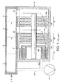
図2は、複合多ポート真空ポンプ100の第1実施形態を示す。ポンプは、多構成要素本体102を含み、駆動シャフト104が本体内に取り付けられている。シャフトの回転は、シャフトのまわりに位置決めされたモータ(図示せず)、例えば、ブラシレス直流モータによって行われる。シャフト104は、対向した軸受(図示せず)に取り付けられている。例えば、駆動シャフト104は、ハイブリッド永久磁石軸受及びオイル潤滑軸受装置によって支持されるのがよい。
FIG. 2 shows a first embodiment of a composite
ポンプは、少なくとも3つの排気部分106、108、110を含む。第1排気部分106は、ターボ分子段組からなる。図2に示す実施形態では、ターボ分子段組106は、周知の角度構造の4つのロータブレード及び3つのステータブレードからなる。ロータブレードを107aで指示し、ステータブレードを107bで指示する。この例では、ロータブレード107aは駆動シャフト104に取り付けられる。
The pump includes at least three
第2排気部分108は、第1排気部分106と同様であり、かつまたターボ分子段組からなる。図2に示す実施形態では、ターボ分子段組108も、周知の角度構造の4つのロータブレード及び3つのステータブレードからなる。ロータブレードを109aで指示し、ステータブレードを109bで指示する。この例では、ロータブレード109aも駆動シャフト104に取り付けられる。
The
第1及び第2排気部分の下流に、第3排気部分110がある。図2に示す実施形態では、第3排気部分は、分子ドラッグ排気機構112及び再生排気機構114からなる。
There is a
分子ドラッグ排気機構112は、ホルウィックドラッグ機構の形態をなしている。この実施形態では、ホルウィック機構は、回転シリンダ116及びそれに対応する環状ステータ118a、118bからなり、環状ステータには、螺旋チャンネルがそれ自体周知の方法で形成されている。この実施形態では、ホルウィック機構は、2つの排気段からなるが、圧力、流量及び容量要求に応じて、任意の数の段を設けてもよい。回転シリンダ116は、好ましくは、炭素繊維材料で形成され、そして好ましくは、駆動シャフト104に位置したディスク120の形態をなしたロータ要素120に取り付けられている。この例では、ディスク120も駆動シャフト104に取り付けられている。
The molecular
再生排気機構114は、ホルウィック機構112のディスク120の片側に取り付けられ、或いはそれと一体のブレード122の少なくとも1つの環状列の形態をなした複数のロータからなる。この実施形態では、再生排気機構114は、ロータ122の2つの同心の環状列からなるが、圧力、流量及び容量要求に応じて任意の数の環状列を設けてもよい。
The
分子ドラッグ排気機構112のステータ118bは、再生排気機構114のステータをも形成し、該ステータには、環状チャンネル124a、124bが形成され、ロータ122は、この環状チャンネルの中で回転する。知られているように、チャンネル124a、124bは、ロータのための厳密な隙間をもたらす減少した断面を有する「ストリッパ」として知られるチャンネルの小さい部分を除いて、ここのブレード122の断面積よりも大きい断面積を有する。使用中、排気された排気流体はストリッパの一端に臨床装置決して位置した入口を経て最も外側の環状チャンネル124aに入り、流体は、ロータ122によってチャンネルに沿って押され、遂には、流体は、ストッパの他端に当たる。次いで、流体は、ポートを通して最も内側の環状チャンネル124bに押し入れられ、流体は、出口126までチャンネル124に沿って押される。
The
再生排気機構114の下流には、ポンプ出口126がある。補助ポンプ128は、出口126を経てポンプ100を補助する。
A
図2に示すように、ポンプ100は、2つの入口130、132を有しており、この実施形態では、たった2つの入口が使用されているけれども、ポンプは、選択的に開閉させることができ、且つ異なる流量流れを機構の特定部分に案内するため内バッフルを使用することができる追加の選択的な入口134を有するのがよい。入口130は排気部分の全ての上流に置かれる。入口132は、第1排気部分106と第2排気部分108の段間に置かれる。選択的な入口134は、第2排気部分108と第3排気部分110の段間に置かれ、分子ドラッグ排気機構112の段の全ては、選択的入口と連通する。
As shown in FIG. 2, the
使用中、各入口は、差動排気装置、即ちこの例では、図1に示すように同じ質量分析計装置のそれぞれの室に連結される。かくして、入口130は低圧力室10に連結され、入口132は中間圧力室14に連結される。他の室12が高圧力室11と中間圧力室14との間にある場合には、点線136で指示されているように、選択的な入口134は開かれ、そしてこの室12に連結される。追加の低圧力室を装置に加え、そして別の手段によって排気してもよい。高圧力インターフェース室11は補助ラインを介して補助ポンプに連結され、該補助ポンプも、複合真空ポンプ100の出口126から流体を排気する。
In use, each inlet is connected to a differential evacuation device, ie, in this example, a respective chamber of the same mass spectrometer device as shown in FIG. Thus, the
使用中、低圧力室10から入口130を通過する流体は、第1排気部分106、第2排気部分108、及び第3排気部分110を通過し、そしてポンプ出口126を経てポンプ100を出る。中間圧力室14から入口122を通過する流体は、ポンプ100に入り、第2排気部分108及び第3排気部分110を通過し、ポンプ出口126を経てポンプ100を出る。開かれるならば、室12から選択的な入口124を通過する流体は、ポンプ100に入り、第3は排気部分110だけを通過し、そしてポンプ出口126を経てポンプ100を出る。
In use, fluid passing from the
この例では、使用中、図1を参照して説明した装置と同様に、第1インターフェース室11は1−10ミリバール位の圧力であり、第2インターフェース室12(使用される場合)は10-1−1ミリバールの圧力であり、第3インターフェース室14は10-2−10-3ミリバール位の圧力であり、高真空室10は10-5−10-6ミリバール位の圧力である。しかしながら、ポンプを通過するガスの、再生排気機構112による圧縮のために、再生排気機構は、補助ライン138内の圧力よりも低い補助圧力を分子ドラッグ排気段110に送出するのに役立つ。これは、ポンプの電力消費を著しく減じ、且つポンプ性能を著しく改善することができる。
In this example, during use, the
その上、図2に指示されているように、再生排気機構114のロータ122は、分子ドラッグ排気機構112の回転シリンダ116によって取り囲まれている。かくして、再生排気機構114を、真空ポンプの全体の長さ又はサイズの増大が殆ど無く、又は全く無く、第1実施形態の真空ポンプ100に都合よく含める事が出来る。
In addition, as indicated in FIG. 2, the
図3に示すように、この実施形態では、ターボ分子部分106、108のロータ107、109、分子ドラッグ機構112の回転ディスク120、及び再生排気機構114のロータ122は、駆動シャフト104に取り付けられた共通のインペラー145に置かれ、分子ドラッグ排気機構112の炭素繊維製の回転シリンダ116は、これらの一体の回転要素の機械加工に続いて回転ディスク120に取り付けられる。しかしながら、これらの回転要素の1つだけ又はそれ以上はインペラー145と一体でもよく、残りの要素は図2におけるように、駆動シャフトに取り付けられ、或いは要求されるように、他のインペラーに置かれてもよい。インペラー145の右端(図示のように)は磁石軸受で支持され、この軸受の永久磁石はインペラーに置かれ、駆動シャフト104の左端(図示のように)は潤滑軸受で支持されるのがよい。
As shown in FIG. 3, in this embodiment, the rotors 107 and 109 of the turbo
図4は、複合多ポート真空ポンプ200の第2実施形態を示す。この第2実施形態は、図1を参照して上で説明した差動排気質量分析計装置で全体の質量流量の99%以上を排気するのに適している点で第1実施形態と異なる。これは、通常の第2及び第3最高圧力室に加えて、最高圧力室を直接排気することができるように構成されている真空ポンプ200によって達成される。ポンプ200は、入口130、132及び選択的な入口134のみならず、分子ドラッグ排気機構112の段の流に或いは、図4に示すように、その段の間に置かれた追加の入口240を含み、その結果、分子ドラッグ排気機構112の段の全ては、入口130、132と連通しており、図4に示す構成では、段の一部分だけ(1つ又はそれ以上)月以下の入口240と連通している。
FIG. 4 shows a second embodiment of the composite
使用中、入口130は、低圧室10に連結され、入口132は、中間圧力室14に連結され、追加の入口240は、最高圧力室11に連結される。第4室12が、点線136で指示されているように、高圧室11と中間圧力室14の間にある場合には、選択的な入口134は開かれ、そして第4室12に連結される。追加の低圧力室を装置に加えてもよく、また別の手段によって排気してもよいが、これらの追加の室の質量流量は、典型的には、分析計装置の全体の質量流量の1%よりも大変小さい。
In use, the
使用中、真空ポンプ200は、差動排気質量分析計装置の室に、第1実施形態の真空ポンプ100と同様の性能利点を生じさせることができる。第1実施形態によって提供された潜在的な性能利点に加えて、この第2実施形態も多数の他の性能を提供することができる。これらの利点のうちの第1のものは、差動排気質量分析計装置の高圧室を、補助ポンプ128によってではなく、第2及び第3最高圧力室を排気する同じ複合多ポート真空ポンプ200によって直接排気することができることによって、複合多ポート真空ポンプが質量分析計装置の全体の流体質量流量の99%以上をなしとげることができる。かくして、内部的にリンクした分析計装置の高圧室及び残部の性能を、補助ポンプのサイズを増すこと無く増大させる事が出来る。
In use, the
これらの利点のうちの第2のものは、異なる性能レベルのポンプ、例えば、50又は60Hzでオンラインで直接作動する補助ポンプで補助される時装置の性能及び電力の一貫性である。この第2実施形態の場合には、図4を参照して説明した装置では、装置の性能の変動が、補助ポンプ128の作動周波数が50Hzと60Hzの間で変えられれば、1%位になり、かくして使用者に安定な装置性能及び電力の融通性のある排気装置を提供することが予想される。(質量分析計の設計に応じて、この利点は、たとえ小さい程度でも、第1実施形態によっても与えられることに気付くべきである。「自由噴射膨張(free jet expansion)」がときどき質量分析計装置に付与され、その結果、第1室の圧力は引き続く室の圧力に殆ど影響を及ぼさない。かくして、低圧室の性能に強く影響を及ぼす唯一の要因は、複合ポンプそれ自体である。再生排気機構は、変化が補助圧力に対して起こる時、性能をより良く安定化させることを確実にする、と言うのは、変化がポンプ性能をより高い補助圧力に維持するからである。例え低圧力でも、再生排気機構は、補助性能を「制限する」のに役立ち、かくしてもっと一定の補助圧力をポンプの残部に与える。)
The second of these benefits is the consistency of device performance and power when assisted by pumps of different performance levels, eg, auxiliary pumps that operate directly online at 50 or 60 Hz. In the case of the second embodiment, in the apparatus described with reference to FIG. 4, the fluctuation in the performance of the apparatus is about 1% if the operating frequency of the
第2の実施形態の他の利点は、補助ポンプ128が最早流体を高圧室11から直接吸引しない時、補助ポンプ128の容量、かくして、サイズを第1実施形態と比較して著しく減少させることができる。(再び、「自由噴射膨張」が使用される場合、たとえ小さい程度でも、第1実施形態によって同様な利点が与えられることに気付くべきである。)。これは、再生排気機構114によって、真空ポンプ200が10ミリバール以上の圧力で利稀有対を排気することができるからである。対象的に、図1に記載した先行技術の真空ポンプ100は、典型的には、1−10ミリバール位の圧力で流体を排気し、従って補助ポンプのサイズをこの第2実施形態では著しく減少させることができる。このサイズの減少は、装置の性能に悪影響を及ぼすことなく、ある質量分析計装置では10のファクター程になる。かくして、真空ポンプ200と補助ポンプ128の両方を含む第2実施形態の全体の排気装置は、サイズが減ぜられ、恐らく、卓上取付け包囲体内に都合よく収容される。
Another advantage of the second embodiment is that when the
図5は、差動排気質量分析計装置から全体の質量流量の99%以上を排気するのに適した真空ポンプ300の第3実施形態を示し、そして、第2実施形態と同様であり、高圧室11から入口340を通過する流体がポンプ300に入り、分子ドラッグ排気機構112を通過することなく再生排気機構114を通過し、ポンプ出口126を経てポンプを出る。その上、図5に示すように、再生排気機構114の少なくとも一部がゲーデ又は他の分子ドラッグ機構350で置き換えられる。再生排気機構114をゲーデ機構350で置き換える程度は、真空ポンプ350の所要の排気性能に依存する。例えば、再生排気機構114を全体的に置き換えてもよいし、或いは図示したように、ゲーデ機構で部分的に置き換えてもよい。
FIG. 5 shows a third embodiment of a
Claims (23)
ホルウィック分子ドラッグ排気機構(112)のロータ要素(116)は、炭素繊維材料で形成された、再生排気機構(114)のロータ要素(122)とともに回転運動可能に取り付けられたシリンダ(116)からなり、
ホルウィック分子ドラッグ排気機構のロータ要素(116)及び再生排気機構のロータ要素(122)は、真空ポンプの共通のロータ(120)に配置され、該ロータ(120)は、真空ポンプの駆動シャフト(104)に取り付けられたインペラー(145)と一体であり、かつ真空ポンプの駆動シャフトと直交するディスク(120)によって提供され、
再生排気機構のロータ要素(122)は、ロータ(120)と一体で、ロータ(120)の片側に同心の環状列をなして位置決めされた少なくとも2連のブレード(122)からなり、ブレード(122)の軸線方向先端位置は同じであり、分子ドラッグ排気機構のロータ要素(116)は、ロータの、再生排気機構のロータ要素(122)と同じ側に設けられている、真空ポンプ。A vacuum pump (100) including a Holwick molecular drag exhaust mechanism (112) and a regeneration exhaust mechanism (114) downstream thereof, wherein the rotor element (116) of the molecular drag exhaust mechanism is a rotor element ( 122)
The rotor element (116) of the Holwick molecular drag exhaust mechanism (112) comprises a cylinder (116) made of carbon fiber material and mounted for rotational movement together with the rotor element (122) of the regenerative exhaust mechanism (114). ,
The rotor element (116) of the Holwick molecular drag exhaust mechanism and the rotor element (122) of the regenerative exhaust mechanism are arranged in a common rotor (120) of the vacuum pump, and the rotor (120) is connected to the drive shaft (104) of the vacuum pump. Provided by a disk (120) that is integral with the impeller (145) attached to the vacuum pump and orthogonal to the drive shaft of the vacuum pump;
The rotor element (122) of the regenerative exhaust mechanism is composed of at least two blades (122) integrated with the rotor (120) and positioned in a concentric annular row on one side of the rotor (120). axial end position of the) are the same, the rotor element of the molecular drag pumping mechanism (116) of the rotor are provided on the same side as the rotor element (122) of the regenerative pumping mechanism, a vacuum pump.
分子ドラッグ排気機構のロータ要素は、炭素繊維材料で形成された、再生排気機構のロータ要素(122)とともに回転運動可能に取り付けられたシリンダ(116)からなり、
分子ドラッグ排気機構のロータ要素(116)及び再生排気機構のロータ要素(122)は、インペラーの共通のロータ(120)に配置され、
ロータ(120)は、インペラーと一体であり、
ロータ(120)は、インペラーの長手方向軸線と直交するディスク(120)からなり、
再生排気機構のロータ要素(122)は、ロータ(120)と一体で、ロータ(120)の片側に同心の環状列をなして位置決めされた一連のブレード(122)からなり、ブレード(122)の軸線方向先端位置は同じであり、
分子ドラッグ排気機構のロータ要素(116)は、ロータ(120)の前記片側に設けられている、真空ポンプ用のインペラー。An impeller (145) for a vacuum pump, the impeller including a rotor element (116) of a molecular drag exhaust mechanism and a plurality of rotor elements (122) of a regeneration exhaust mechanism, the rotor element of the molecular drag exhaust mechanism (116) surrounds the rotor element (122) of the regenerative exhaust mechanism;
The rotor element of the molecular drag exhaust mechanism consists of a cylinder (116) made of carbon fiber material and mounted for rotational movement with the rotor element (122) of the regenerative exhaust mechanism,
The rotor element (116) of the molecular drag exhaust mechanism and the rotor element (122) of the regeneration exhaust mechanism are arranged in a common rotor ( 120 ) of the impeller,
The rotor (120) is integral with the impeller;
The rotor (120) consists of a disk (120) orthogonal to the longitudinal axis of the impeller,
The regenerative exhaust mechanism rotor element (122) comprises a series of blades (122) integral with the rotor (120) and positioned in a concentric annular row on one side of the rotor (120). The axial tip position is the same,
The rotor element (116) of the molecular drag exhaust mechanism is an impeller for a vacuum pump provided on the one side of the rotor (120).
Applications Claiming Priority (5)
| Application Number | Priority Date | Filing Date | Title |
|---|---|---|---|
| GB0322888.9 | 2003-09-30 | ||
| GB0322888A GB0322888D0 (en) | 2003-09-30 | 2003-09-30 | Vacuum pump |
| GBGB0409139.3A GB0409139D0 (en) | 2003-09-30 | 2004-04-23 | Vacuum pump |
| GB0409139.3 | 2004-04-23 | ||
| PCT/GB2004/004110 WO2005033520A1 (en) | 2003-09-30 | 2004-09-23 | Vacuum pump |
Related Child Applications (1)
| Application Number | Title | Priority Date | Filing Date |
|---|---|---|---|
| JP2011089466A Division JP5637919B2 (en) | 2003-09-30 | 2011-04-13 | Compound vacuum pump |
Publications (2)
| Publication Number | Publication Date |
|---|---|
| JP2007507657A JP2007507657A (en) | 2007-03-29 |
| JP4843493B2 true JP4843493B2 (en) | 2011-12-21 |
Family
ID=34424883
Family Applications (5)
| Application Number | Title | Priority Date | Filing Date |
|---|---|---|---|
| JP2006530557A Expired - Fee Related JP4843493B2 (en) | 2003-09-30 | 2004-09-23 | Vacuum pump |
| JP2006530555A Expired - Fee Related JP5546094B2 (en) | 2003-09-30 | 2004-09-23 | Vacuum pump |
| JP2011089466A Expired - Fee Related JP5637919B2 (en) | 2003-09-30 | 2011-04-13 | Compound vacuum pump |
| JP2013213093A Expired - Fee Related JP5809218B2 (en) | 2003-09-30 | 2013-10-10 | Vacuum pump |
| JP2013213092A Pending JP2014001743A (en) | 2003-09-30 | 2013-10-10 | Vacuum pump |
Family Applications After (4)
| Application Number | Title | Priority Date | Filing Date |
|---|---|---|---|
| JP2006530555A Expired - Fee Related JP5546094B2 (en) | 2003-09-30 | 2004-09-23 | Vacuum pump |
| JP2011089466A Expired - Fee Related JP5637919B2 (en) | 2003-09-30 | 2011-04-13 | Compound vacuum pump |
| JP2013213093A Expired - Fee Related JP5809218B2 (en) | 2003-09-30 | 2013-10-10 | Vacuum pump |
| JP2013213092A Pending JP2014001743A (en) | 2003-09-30 | 2013-10-10 | Vacuum pump |
Country Status (8)
| Country | Link |
|---|---|
| US (4) | US8851865B2 (en) |
| EP (4) | EP2375080B1 (en) |
| JP (5) | JP4843493B2 (en) |
| CN (3) | CN102062109B (en) |
| AT (1) | ATE535715T1 (en) |
| CA (4) | CA2747137C (en) |
| GB (1) | GB0409139D0 (en) |
| WO (2) | WO2005033520A1 (en) |
Families Citing this family (40)
| Publication number | Priority date | Publication date | Assignee | Title |
|---|---|---|---|---|
| GB0409139D0 (en) | 2003-09-30 | 2004-05-26 | Boc Group Plc | Vacuum pump |
| GB0322883D0 (en) * | 2003-09-30 | 2003-10-29 | Boc Group Plc | Vacuum pump |
| US20120027583A1 (en) * | 2006-05-04 | 2012-02-02 | Bernd Hofmann | Vacuum pump |
| DE102006020710A1 (en) * | 2006-05-04 | 2007-11-08 | Pfeiffer Vacuum Gmbh | Vacuum pump with housing |
| US8288719B1 (en) * | 2006-12-29 | 2012-10-16 | Griffin Analytical Technologies, Llc | Analytical instruments, assemblies, and methods |
| DE102007010068A1 (en) * | 2007-02-28 | 2008-09-04 | Thermo Fisher Scientific (Bremen) Gmbh | Vacuum pump or vacuum device for evacuation of multiple volumes, has two suction inlets with multiple pressure stages and outer suction inlet for one pressure stage spatially encompasses inner suction inlet for another pressure stage |
| DE102007027352A1 (en) * | 2007-06-11 | 2008-12-18 | Oerlikon Leybold Vacuum Gmbh | Mass Spectrometer arrangement |
| US9343280B2 (en) | 2007-09-07 | 2016-05-17 | Perkinelmer Health Sciences Canada, Inc. | Multi-pressure stage mass spectrometer and methods |
| CN101398406B (en) * | 2007-09-30 | 2012-03-07 | 孔令昌 | Portable mass spectrometer |
| DE102008009715A1 (en) * | 2008-02-19 | 2009-08-20 | Oerlikon Leybold Vacuum Gmbh | Vacuum pumping system and use of a multi-stage vacuum pump |
| US8673394B2 (en) * | 2008-05-20 | 2014-03-18 | Sundew Technologies Llc | Deposition method and apparatus |
| KR101297743B1 (en) | 2008-10-10 | 2013-08-20 | 가부시키가이샤 아루박 | Dry pump |
| GB0901872D0 (en) * | 2009-02-06 | 2009-03-11 | Edwards Ltd | Multiple inlet vacuum pumps |
| GB2472638B (en) * | 2009-08-14 | 2014-03-19 | Edwards Ltd | Vacuum system |
| GB2474507B (en) | 2009-10-19 | 2016-01-27 | Edwards Ltd | Vacuum pump |
| DE102010019940B4 (en) * | 2010-05-08 | 2021-09-23 | Pfeiffer Vacuum Gmbh | Vacuum pumping stage |
| DE102012003680A1 (en) | 2012-02-23 | 2013-08-29 | Pfeiffer Vacuum Gmbh | vacuum pump |
| WO2014125238A1 (en) * | 2013-02-15 | 2014-08-21 | Edwards Limited | Vacuum pump |
| DE202013005458U1 (en) | 2013-06-15 | 2014-09-16 | Oerlikon Leybold Vacuum Gmbh | vacuum pump |
| DE102013214662A1 (en) * | 2013-07-26 | 2015-01-29 | Pfeiffer Vacuum Gmbh | vacuum pump |
| GB201314841D0 (en) * | 2013-08-20 | 2013-10-02 | Thermo Fisher Scient Bremen | Multiple port vacuum pump system |
| DE102013109637A1 (en) * | 2013-09-04 | 2015-03-05 | Pfeiffer Vacuum Gmbh | Vacuum pump and arrangement with a vacuum pump |
| DE102014101257A1 (en) | 2014-02-03 | 2015-08-06 | Pfeiffer Vacuum Gmbh | vacuum pump |
| EP3032106B1 (en) * | 2014-12-08 | 2020-02-12 | Pfeiffer Vacuum Gmbh | Vacuum pump |
| GB2533153B (en) * | 2014-12-12 | 2017-09-20 | Thermo Fisher Scient (Bremen) Gmbh | Vacuum system |
| DE102014226038A1 (en) * | 2014-12-16 | 2016-06-16 | Carl Zeiss Microscopy Gmbh | Pressure reducing device, apparatus for mass spectrometric analysis of a gas and cleaning method |
| US9368335B1 (en) * | 2015-02-02 | 2016-06-14 | Thermo Finnigan Llc | Mass spectrometer |
| JP6488898B2 (en) | 2015-06-09 | 2019-03-27 | 株式会社島津製作所 | Vacuum pump and mass spectrometer |
| EP3112688B2 (en) * | 2015-07-01 | 2022-05-11 | Pfeiffer Vacuum GmbH | Split flow vacuum pump and vacuum system with a split flow vacuum pump |
| JP6578838B2 (en) * | 2015-09-15 | 2019-09-25 | 株式会社島津製作所 | Vacuum pump and mass spectrometer |
| EP3327293B1 (en) * | 2016-11-23 | 2019-11-06 | Pfeiffer Vacuum Gmbh | Vacuum pump having multiple inlets |
| JP7108377B2 (en) * | 2017-02-08 | 2022-07-28 | エドワーズ株式会社 | Vacuum pumps, rotating parts of vacuum pumps, and unbalance correction methods |
| GB201715151D0 (en) * | 2017-09-20 | 2017-11-01 | Edwards Ltd | A drag pump and a set of vacuum pumps including a drag pump |
| KR101838660B1 (en) * | 2017-12-04 | 2018-03-14 | (주)대명엔지니어링 | Vacuum pump |
| GB2569633A (en) * | 2017-12-21 | 2019-06-26 | Edwards Ltd | A vacuum pumping arrangement and method of cleaning the vacuum pumping arrangement |
| DE202018000285U1 (en) * | 2018-01-18 | 2019-04-23 | Leybold Gmbh | Vacuum system |
| DE102018119747B3 (en) | 2018-08-14 | 2020-02-13 | Bruker Daltonik Gmbh | TURBOMOLECULAR PUMP FOR MASS SPECTROMETERS |
| GB2584603B (en) * | 2019-04-11 | 2021-10-13 | Edwards Ltd | Vacuum chamber module |
| EP3623634B1 (en) * | 2019-08-13 | 2022-04-06 | Pfeiffer Vacuum Gmbh | Vacuum pump comprising a holweck pump stage and two side channel pump stages |
| US11710950B2 (en) | 2021-01-20 | 2023-07-25 | Te Connectivity Solutions Gmbh | Cutting blade and cutting depth control device |
Citations (4)
| Publication number | Priority date | Publication date | Assignee | Title |
|---|---|---|---|---|
| JPH02264196A (en) * | 1989-04-04 | 1990-10-26 | Hitachi Ltd | Turbine vacuum pump |
| JPH06280785A (en) * | 1992-12-24 | 1994-10-04 | Balzers Pfeiffer Gmbh | Vacuum pump device for multistage gas suction device |
| JPH11351190A (en) * | 1998-05-20 | 1999-12-21 | Boc Group Plc:The | Vacuum pump |
| JP2002285987A (en) * | 2001-03-28 | 2002-10-03 | Chiba Seimitsu:Kk | Small-size vacuum pump |
Family Cites Families (41)
| Publication number | Priority date | Publication date | Assignee | Title |
|---|---|---|---|---|
| DE2409857B2 (en) | 1974-03-01 | 1977-03-24 | Leybold-Heraeus GmbH & Co KG, 5000Köln | TURBOMOLECULAR VACUUM PUMP WITH AT LEAST PARTIAL BELL-SHAPED ROTOR |
| DE2442614A1 (en) * | 1974-09-04 | 1976-03-18 | Siemens Ag | Rotary high vacuum pump - has second inlet opening so that it can produce two levels of vacuum |
| JPS6172896A (en) | 1984-09-17 | 1986-04-14 | Japan Atom Energy Res Inst | High speed rotary pump |
| JPS62279282A (en) * | 1986-05-27 | 1987-12-04 | Mitsubishi Electric Corp | Turbomolecular pump |
| JPS6355396A (en) * | 1986-08-21 | 1988-03-09 | Hitachi Ltd | Turbo vacuum pump |
| JPS6375386A (en) | 1986-09-18 | 1988-04-05 | Mitsubishi Heavy Ind Ltd | Hybrid vacuum pump |
| US5020969A (en) † | 1988-09-28 | 1991-06-04 | Hitachi, Ltd. | Turbo vacuum pump |
| JPH02108895A (en) † | 1988-10-17 | 1990-04-20 | Hitachi Ltd | Turbo vacuum pump |
| JPH02136595A (en) | 1988-11-16 | 1990-05-25 | Anelva Corp | Vacuum pump |
| DE69016198T2 (en) * | 1990-07-06 | 1995-05-18 | Cit Alcatel | Second stage for mechanical vacuum pump unit and leak monitoring system for using this unit. |
| DE4228313A1 (en) * | 1992-08-26 | 1994-03-03 | Leybold Ag | Counterflow leak detector with high vacuum pump |
| US5733104A (en) * | 1992-12-24 | 1998-03-31 | Balzers-Pfeiffer Gmbh | Vacuum pump system |
| JP2656199B2 (en) * | 1993-01-11 | 1997-09-24 | アプライド マテリアルズ インコーポレイテッド | Opening method of vacuum chamber and PVD apparatus |
| DE4314418A1 (en) * | 1993-05-03 | 1994-11-10 | Leybold Ag | Friction vacuum pump with differently designed pump sections |
| CN1110376A (en) * | 1994-04-16 | 1995-10-18 | 储继国 | Driven molecular pump |
| DE19508566A1 (en) * | 1995-03-10 | 1996-09-12 | Balzers Pfeiffer Gmbh | Molecular vacuum pump with cooling gas device and method for its operation |
| JP3095338B2 (en) * | 1995-06-19 | 2000-10-03 | 富士通株式会社 | Turbo molecular pump |
| GB9725146D0 (en) * | 1997-11-27 | 1998-01-28 | Boc Group Plc | Improvements in vacuum pumps |
| JPH11230036A (en) * | 1998-02-18 | 1999-08-24 | Ebara Corp | Evacuating system |
| DE19821634A1 (en) * | 1998-05-14 | 1999-11-18 | Leybold Vakuum Gmbh | Friction vacuum pump with staged rotor and stator |
| DE59912626D1 (en) * | 1998-05-26 | 2006-02-16 | Leybold Vakuum Gmbh | FRESH VACUUM PUMP WITH CHASSIS, ROTOR AND HOUSING, AND EQUIPMENT, EQUIPPED WITH A FRESH VACUUM PUMP OF THIS ART |
| US6193461B1 (en) * | 1999-02-02 | 2001-02-27 | Varian Inc. | Dual inlet vacuum pumps |
| DE19915307A1 (en) * | 1999-04-03 | 2000-10-05 | Leybold Vakuum Gmbh | Turbomolecular friction vacuum pump, with annular groove in region of at least one endface of rotor |
| DE19930952A1 (en) * | 1999-07-05 | 2001-01-11 | Pfeiffer Vacuum Gmbh | Vacuum pump |
| GB9927493D0 (en) * | 1999-11-19 | 2000-01-19 | Boc Group Plc | Improved vacuum pumps |
| DE10022062A1 (en) * | 2000-05-06 | 2001-11-08 | Leybold Vakuum Gmbh | Machine, preferably turbo-molecular vacuum pumps, has magnet bearings each comprising concentrically-arranged magnet ring stacks |
| JP2001323892A (en) * | 2000-05-16 | 2001-11-22 | Shimadzu Corp | Turbo type vacuum instrument |
| DE10032607B4 (en) * | 2000-07-07 | 2004-08-12 | Leo Elektronenmikroskopie Gmbh | Particle beam device with a particle source to be operated in ultra-high vacuum and a cascade-shaped pump arrangement for such a particle beam device |
| US6793466B2 (en) * | 2000-10-03 | 2004-09-21 | Ebara Corporation | Vacuum pump |
| JP2002138987A (en) * | 2000-10-31 | 2002-05-17 | Seiko Instruments Inc | Vacuum pump |
| DE10055057A1 (en) * | 2000-11-07 | 2002-05-08 | Pfeiffer Vacuum Gmbh | Leak detector pump has high vacuum pump, gas analyzer, test object connector, gas outlet opening, gas inlet opening, valve bodies and gas connections in or forming parts of housing |
| CN1399076A (en) * | 2001-07-27 | 2003-02-26 | 大晃机械工业株式会社 | Vacuum pump |
| GB0124731D0 (en) | 2001-10-15 | 2001-12-05 | Boc Group Plc | Vacuum pumps |
| JP3961273B2 (en) * | 2001-12-04 | 2007-08-22 | Bocエドワーズ株式会社 | Vacuum pump |
| GB0229353D0 (en) * | 2002-12-17 | 2003-01-22 | Boc Group Plc | Vacuum pumping system and method of operating a vacuum pumping arrangement |
| GB0229356D0 (en) * | 2002-12-17 | 2003-01-22 | Boc Group Plc | Vacuum pumping arrangement |
| GB0229355D0 (en) * | 2002-12-17 | 2003-01-22 | Boc Group Plc | Vacuum pumping arrangement |
| GB0229352D0 (en) * | 2002-12-17 | 2003-01-22 | Boc Group Plc | Vacuum pumping arrangement and method of operating same |
| ITTO20030421A1 (en) * | 2003-06-05 | 2004-12-06 | Varian Spa | COMPACT VACUUM PUMP |
| GB0409139D0 (en) * | 2003-09-30 | 2004-05-26 | Boc Group Plc | Vacuum pump |
| GB0411426D0 (en) * | 2004-05-21 | 2004-06-23 | Boc Group Plc | Pumping arrangement |
-
2004
- 2004-04-23 GB GBGB0409139.3A patent/GB0409139D0/en not_active Ceased
- 2004-09-23 CA CA2747137A patent/CA2747137C/en not_active Expired - Fee Related
- 2004-09-23 CN CN2011100487470A patent/CN102062109B/en active Active
- 2004-09-23 EP EP11169892.4A patent/EP2375080B1/en active Active
- 2004-09-23 EP EP04768653.0A patent/EP1668255B2/en not_active Not-in-force
- 2004-09-23 US US10/572,894 patent/US8851865B2/en active Active
- 2004-09-23 CN CN2004800268965A patent/CN101124409B/en active Active
- 2004-09-23 CA CA2563234A patent/CA2563234C/en active Active
- 2004-09-23 EP EP11169894.0A patent/EP2378129B1/en active Active
- 2004-09-23 JP JP2006530557A patent/JP4843493B2/en not_active Expired - Fee Related
- 2004-09-23 JP JP2006530555A patent/JP5546094B2/en not_active Expired - Fee Related
- 2004-09-23 CA CA2563306A patent/CA2563306C/en not_active Expired - Fee Related
- 2004-09-23 WO PCT/GB2004/004110 patent/WO2005033520A1/en active Application Filing
- 2004-09-23 EP EP04768590.4A patent/EP1668254B1/en active Active
- 2004-09-23 US US10/574,027 patent/US7866940B2/en active Active
- 2004-09-23 AT AT04768653T patent/ATE535715T1/en active
- 2004-09-23 CN CN2004800284031A patent/CN1860301B/en active Active
- 2004-09-23 CA CA2747136A patent/CA2747136C/en not_active Expired - Fee Related
- 2004-09-23 WO PCT/GB2004/004046 patent/WO2005040615A2/en active Application Filing
-
2010
- 2010-12-13 US US12/966,566 patent/US8672607B2/en active Active
-
2011
- 2011-04-13 JP JP2011089466A patent/JP5637919B2/en not_active Expired - Fee Related
-
2013
- 2013-10-10 JP JP2013213093A patent/JP5809218B2/en not_active Expired - Fee Related
- 2013-10-10 JP JP2013213092A patent/JP2014001743A/en active Pending
-
2014
- 2014-08-28 US US14/471,698 patent/US9249805B2/en not_active Expired - Fee Related
Patent Citations (4)
| Publication number | Priority date | Publication date | Assignee | Title |
|---|---|---|---|---|
| JPH02264196A (en) * | 1989-04-04 | 1990-10-26 | Hitachi Ltd | Turbine vacuum pump |
| JPH06280785A (en) * | 1992-12-24 | 1994-10-04 | Balzers Pfeiffer Gmbh | Vacuum pump device for multistage gas suction device |
| JPH11351190A (en) * | 1998-05-20 | 1999-12-21 | Boc Group Plc:The | Vacuum pump |
| JP2002285987A (en) * | 2001-03-28 | 2002-10-03 | Chiba Seimitsu:Kk | Small-size vacuum pump |
Also Published As
Similar Documents
| Publication | Publication Date | Title |
|---|---|---|
| JP4843493B2 (en) | Vacuum pump | |
| US8764413B2 (en) | Pumping arrangement | |
| JP5378432B2 (en) | Pumping device | |
| JP4806636B2 (en) | Vacuum pump | |
| JP5319118B2 (en) | Vacuum pump | |
| JP2007507658A (en) | Vacuum pump |
Legal Events
| Date | Code | Title | Description |
|---|---|---|---|
| A621 | Written request for application examination |
Free format text: JAPANESE INTERMEDIATE CODE: A621 Effective date: 20070807 |
|
| A711 | Notification of change in applicant |
Free format text: JAPANESE INTERMEDIATE CODE: A711 Effective date: 20071119 |
|
| A521 | Request for written amendment filed |
Free format text: JAPANESE INTERMEDIATE CODE: A523 Effective date: 20080205 |
|
| A131 | Notification of reasons for refusal |
Free format text: JAPANESE INTERMEDIATE CODE: A131 Effective date: 20100329 |
|
| A521 | Request for written amendment filed |
Free format text: JAPANESE INTERMEDIATE CODE: A523 Effective date: 20100629 |
|
| A02 | Decision of refusal |
Free format text: JAPANESE INTERMEDIATE CODE: A02 Effective date: 20101213 |
|
| A521 | Request for written amendment filed |
Free format text: JAPANESE INTERMEDIATE CODE: A523 Effective date: 20110413 |
|
| A521 | Request for written amendment filed |
Free format text: JAPANESE INTERMEDIATE CODE: A523 Effective date: 20110524 |
|
| A911 | Transfer to examiner for re-examination before appeal (zenchi) |
Free format text: JAPANESE INTERMEDIATE CODE: A911 Effective date: 20110527 |
|
| A131 | Notification of reasons for refusal |
Free format text: JAPANESE INTERMEDIATE CODE: A131 Effective date: 20110822 |
|
| A521 | Request for written amendment filed |
Free format text: JAPANESE INTERMEDIATE CODE: A523 Effective date: 20110829 |
|
| TRDD | Decision of grant or rejection written | ||
| A01 | Written decision to grant a patent or to grant a registration (utility model) |
Free format text: JAPANESE INTERMEDIATE CODE: A01 Effective date: 20111003 |
|
| A01 | Written decision to grant a patent or to grant a registration (utility model) |
Free format text: JAPANESE INTERMEDIATE CODE: A01 |
|
| A61 | First payment of annual fees (during grant procedure) |
Free format text: JAPANESE INTERMEDIATE CODE: A61 Effective date: 20111007 |
|
| R150 | Certificate of patent or registration of utility model |
Ref document number: 4843493 Country of ref document: JP Free format text: JAPANESE INTERMEDIATE CODE: R150 Free format text: JAPANESE INTERMEDIATE CODE: R150 |
|
| FPAY | Renewal fee payment (event date is renewal date of database) |
Free format text: PAYMENT UNTIL: 20141014 Year of fee payment: 3 |
|
| R250 | Receipt of annual fees |
Free format text: JAPANESE INTERMEDIATE CODE: R250 |
|
| R250 | Receipt of annual fees |
Free format text: JAPANESE INTERMEDIATE CODE: R250 |
|
| S531 | Written request for registration of change of domicile |
Free format text: JAPANESE INTERMEDIATE CODE: R313531 |
|
| R250 | Receipt of annual fees |
Free format text: JAPANESE INTERMEDIATE CODE: R250 |
|
| R350 | Written notification of registration of transfer |
Free format text: JAPANESE INTERMEDIATE CODE: R350 |
|
| R250 | Receipt of annual fees |
Free format text: JAPANESE INTERMEDIATE CODE: R250 |
|
| R250 | Receipt of annual fees |
Free format text: JAPANESE INTERMEDIATE CODE: R250 |
|
| R250 | Receipt of annual fees |
Free format text: JAPANESE INTERMEDIATE CODE: R250 |
|
| R250 | Receipt of annual fees |
Free format text: JAPANESE INTERMEDIATE CODE: R250 |
|
| R250 | Receipt of annual fees |
Free format text: JAPANESE INTERMEDIATE CODE: R250 |
|
| LAPS | Cancellation because of no payment of annual fees |