JP4839552B2 - Induction motor control method - Google Patents
Induction motor control method Download PDFInfo
- Publication number
- JP4839552B2 JP4839552B2 JP2001279609A JP2001279609A JP4839552B2 JP 4839552 B2 JP4839552 B2 JP 4839552B2 JP 2001279609 A JP2001279609 A JP 2001279609A JP 2001279609 A JP2001279609 A JP 2001279609A JP 4839552 B2 JP4839552 B2 JP 4839552B2
- Authority
- JP
- Japan
- Prior art keywords
- induction motor
- magnetic flux
- value
- calculation value
- inverter
- Prior art date
- Legal status (The legal status is an assumption and is not a legal conclusion. Google has not performed a legal analysis and makes no representation as to the accuracy of the status listed.)
- Expired - Lifetime
Links
Images

Landscapes
- Control Of Ac Motors In General (AREA)
Description
【0001】
【発明の属する技術分野】
この発明は、可変電圧可変周波数インバータを用い誘導電動機の二次磁束を補正するような該インバータの出力電圧を発生しつつ、所謂、速度センサレスで該電動機を可変速駆動する誘導電動機の制御方法に関する。
【0002】
【従来の技術】
この種の誘導電動機の従来の制御方法としては、例えば特開昭50−121724号公報に開示されているように、可変電圧可変周波数インバータ(以下、単にインバータとも称する)から誘導電動機に給電される無効電力に基づいて該電動機の二次磁束演算値を求め、この磁束演算値が該電動機の二次磁束の定格値になるように前記インバータの出力電圧を補正して、該インバータで駆動される誘導電動機の可変速特性を改善することが行われていた。
【0003】
【発明が解決しようとする課題】
上述の従来の誘導電動機の制御方法では、誘導電動機の二次磁束の補正が行われているが該電動機のすべりに対する補償が行われておらず、その結果、該電動機の負荷が変動すると、前記電動機の回転速度もすべり分だけ変動するという難点があった。
【0004】
この発明の目的は、上記問題点を解決する誘導電動機の制御方法を提供することにある。
【0005】
【課題を解決するための手段】
この第1の発明は、可変電圧可変周波数インバータを用い誘導電動機の二次磁束を補正するような該インバータの出力電圧を発生しつつ、該電動機を可変速駆動する誘導電動機の制御方法において、
前記可変電圧可変周波数インバータから前記誘導電動機への出力電流と、該インバータから該電動機への出力電圧又は該出力電圧を発生させるための該インバータへの出力電圧指令値とに基づいて該電動機の二次磁束演算値とトルク電流演算値とをそれぞれ導出し、前記二次磁束演算値と二次磁束指令値との偏差を入力とする磁束調節器により前記偏差を零にする一次電圧補正値を求め、この一次電圧補正値を前記電圧指令値に加算して電圧指令値を補正するとともに、前記トルク電流演算値によりすべり周波数演算値を求め、すべり周波数演算値により前記誘導電動機への周波数指令を補正することを特徴とする。
【0006】
第2の発明は前記第1の発明の誘導電動機の制御方法において、
前記誘導電動機の二次磁束演算値とトルク電流演算値とをそれぞれ導出する際には、前記誘導電動機の電気定数としての励磁インダクタンスと漏れインダクタンスとを用いることを特徴とする。
【0007】
また、第3の発明は前記誘導電動機の制御方法において、
前記可変電圧可変周波数インバータから前記誘導電動機への出力電流と、該インバータから該電動機への出力電圧又は該出力電圧を発生させるための該インバータへの出力電圧指令値とに基づいて該電動機の二次磁束演算値と軸トルク演算値とをそれぞれ導出し、前記二次磁束演算値と二次磁束指令値との偏差を入力とする磁束調節器により前記偏差を零にする一次電圧補正値を求め、この一次電圧補正値を前記電圧指令値に加算して電圧指令値を補正するとともに、前記軸トルク演算値によりすべり周波数演算値を求め、この求めたすべり周波数演算値により前記誘導電動機への周波数指令を補正することを特徴とする。
【0008】
第4の発明は前記第3の発明の誘導電動機の制御方法において、
前記誘導電動機の二次磁束演算値を導出する際には該電動機の電気定数としての励磁インダクタンスと漏れインダクタンスとを用い、前記誘導電動機の軸トルク演算値を導出する際には該電動機の電気定数としての一次抵抗値を用いることを特徴とする。
【0009】
この発明によれば、可変電圧可変周波数インバータを介して誘導電動機の二次磁束を補正しつつ該電動機を可変速度駆動するときに、後述の如き該電動機のすべり補償機能を付加することにより、該インバータで駆動される誘導電動機の可変速特性をより改善することができる。
【0010】
【発明の実施の形態】
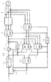
図1は、この発明の第1の実施の形態を示す誘導電動機の制御装置の回路構成図である。
【0011】
図1において、1は後述の制御装置10からの各相の電圧指令vu *,vv *,vw *(交流量)をPWM演算して内蔵するインバータ主回路を形成するそれぞれの半導体スイッチへのオン,オフ駆動信号に変換し、このオン,オフ駆動信号に基づき前記インバータ主回路から三相の出力電圧を発生するインバータ、2はインバータ1から給電される誘導電動機、3はインバータ1から誘導電動機2に流れる各相の電流iu,iv,iwを検出する電流検出器、10はインバータ1を介した誘導電動機2を可変速制御する制御装置である。
【0012】
この制御装置10には磁束指令演算器11と、乗算演算器12と、加算演算器13,14と、電圧指令演算器15と、積分演算器16と、ベクトル回転器17と、磁束・トルク電流演算器18と、加算演算器19と、磁束調節器20と、すべり演算器21とを備えている。
【0013】
図1に示した制御装置10において、先ず、磁束指令演算器11は外部から指令される角周波数指令ω*を誘導電動機2の二次磁束指令φ2 *に変換する演算を行うが、図示の如く角周波数指令ω*が誘導電動機2の定格角周波数までは一定値の二次磁束指令φ2 *を出力し、該定格角周波数を越えると角周波数指令ω*に反比例した値の二次磁束指令φ2 *を出力する。加算演算器13は角周波数指令ω*と後述のすべり角周波数の演算値ωslとを加算した誘導電動機2の一次角周波数指令ω1 *を出力する。乗算演算器12では二次磁束指令φ2 *と一次角周波数指令ω1 *とを乗算して得られる誘導電動機2の一次電圧基準値を出力するが、周知の如く、角周波数指令ω*に比してすべり周波数の演算値ωslの値は僅かであるため、前記一次電圧基準値は角周波数指令ω*が前記定格角周波数までは角周波数指令ω*にほぼ比例して増大し、前記定格角周波数を越えると、この領域では前記一次電圧基準値はほぼ一定値となる。
【0014】
次に、加算演算器14は前記一次電圧基準値に後述の磁束調節器20の出力である誘導電動機2の二次磁束補正のための一次電圧補正値とを加算した誘導電動機2の一次電圧V1の絶対値(大きさ)に対応した出力電圧指令値|V1 *|を出力する。電圧指令演算器15では前記出力電圧指令値|V1 *|に対応した振幅とし、前記一次角周波数指令ω1 *を積分演算器16での時間積分演算で得られる角度指令θ*に基づいた三相の電圧指令vu *,vv *,vw *それぞれに変換している。
【0015】
また、ベクトル回転器17では電流検出器2で得られた検出値iu,iv,iwを前記角度指令θ*に基づくベクトル回転演算により直交した2軸(d−q軸)の値i1d,i1qに変換している。
【0016】
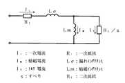
以下に、図1に示した実施形態回路構成図におけるこの発明の主要な構成要素である磁束・トルク電流演算器18,加算演算器19,磁束調節器20,すべり演算器21それぞれの動作を、図2に示す誘導電動機のT−1形等価回路図を参照しつつ、説明する。
【0017】
図2において、誘導電動機の無効電力Qは該電動機の一次角周波数をω1とすると、下記式(1)で表される。
【0018】
【数1】
![]()
また、誘導電動機の二次磁束φ2は、下記式(2)で表される。
【0020】
【数2】
![]()
上記式(1),式(2)から二次磁束φ2は下記式(3)となる。
【0022】
【数3】
すなわち磁束・トルク電流演算器18では一方の演算動作として、前記ω1 *と|V1 *|とi1dとi1qとをそれぞれ入力し、実効値I1及びI1dを求め、前記Qと等価なV1 *・I1dを演算し、これらの値と誘導電動機2の電気定数として温度変化による影響の無い励磁インダクタンスLmと漏れインダクタンスLσとを前記式(3)に当てはめた誘導電動機2の二次磁束演算値φ2Eを導出している。
【0024】
加算演算器19では前記φ2 *とφ2Eとの偏差を求め、この偏差を零にする調節演算を磁束調節器20に行わせ、この調節演算結果を、誘導電動機2の二次磁束φ2を補正するための一次電圧補正値として出力することにより、インバータ1で駆動される誘導電動機2の可変速特性を改善している。
【0025】
また、図2において、一次電流I1とトルク電流ITと励磁電流IMには下記式(4)の関係がある。
【0026】
【数4】
前記式(2),式(3)から励磁電流IMは下記式(5)で表される。
【0028】
【数5】
上記式(4),式(5)からトルク電流ITは、下記式(6)で表される。
【0030】
【数6】
すなわち磁束・トルク電流演算器18では他方の演算動作として、前記ω1 *と|V1 *|とi1dとi1qとをそれぞれ入力し、実効値I1及びI1dを求め、前記Qと等価なV1 *・I1dを演算し、これらの値と誘導電動機2の電気定数としての励磁インダクタンスLmと漏れインダクタンスLσとを前記式(6)に当てはめた誘導電動機2のトルク電流演算値ITEを導出している。
【0032】
すべり演算器21では前記φ2 *とITEとを入力し、さらに誘導電動機2の二次抵抗R2を用いて、該電動機のすべり角周波数の演算値ωslとして、下記式(7)の演算を行っている。
【0033】
【数7】
![]()
図3は、この発明の第2の実施の形態を示す誘導電動機の制御装置の回路構成図であり、図1に示した第1の実施形態回路と同一機能を有するものには同一符号を付して、ここではその説明を省略する。
【0035】
すなわち、図3に示した制御装置30が図1に示した制御装置10と異なる点は、磁束・トルク電流演算器18とすべり演算器21に代えて、磁束演算器31とトルク演算器32とすべり演算器33とを備えていることである。
【0036】
磁束演算器31は前記ω1 *と|V1 *|とi1dとi1qとをそれぞれ入力し、実効値I1及びI1dを求め、前記Qと等価なV1 *・I1dを演算し、これらの値と誘導電動機2の電気定数としての励磁インダクタンスLmと漏れインダクタンスLσとを前記式(3)に当てはめた誘導電動機2の二次磁束演算値φ2Eを導出している。
【0037】
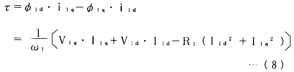
また、トルク演算器32では、前記ω1 *と|V1 *|とi1dとi1qとをそれぞれ入力し、実効値I1d及びI1qを求め、さらに誘導電動機2の一次電圧ベクトルV1d及びV1qを求め、誘導電動機2の一次抵抗R1を用いると、誘導電動機2の軸トルクの演算値τEは誘導電動機2の一次磁束ベクトルφ1d及びφ1qと前記i1d及びi1qの外積から、下記式(8)のように表される。
【0038】
【数8】
すべり演算器33では前記φ2 *とτEとを入力し、トルク電流演算値ITEとしてITE=τE/φ2 *を求め、さらに誘導電動機2の二次抵抗R2を用いて該電動機のすべり角周波数の演算値ωslとして、前記式(7)の演算を行っている。
【0040】
なお、図1及び図3に示したこの発明の実施形態回路では、インバータ1の出力電圧指令値を用いた回路構成であるが、この出力電圧指令値の代わりにインバータ1の出力電圧を検出して誘導電動機2を制御してもよい。
【0041】
【発明の効果】
この発明によれば、誘導電動機が定格周波数以内の運転では出力電圧と出力周波数の比をほぼ一定にし、定格周波数以上の運転では前記出力電圧をほぼ一定にし出力周波数のみ可変にする可変電圧可変周波数インバータ(一般に、VVVFインバータと称される)において、該電動機の二次磁束の補正に加えて、前記電動機のすべりに対する補償も行う制御機能を付加することにより、前記インバータで駆動される誘導電動機の可変速特性をより改善することができる。
【図面の簡単な説明】
【図1】 この発明の第1の実施の形態を示す誘導電動機の制御装置の回路構成図
【図2】 誘導電動機のT−1形等価回路図
【図3】 この発明の第2の実施の形態を示す誘導電動機の制御装置の回路構成図
【符号の説明】
1…インバータ、2…誘導電動機、3…電流検出器、10…制御装置、11…磁束指令演算器、12…乗算演算器、13,14…加算演算器、15…電圧指令演算器、16…積分演算器、17…ベクトル回転器、18…磁束・トルク電流演算器、19…加算演算器、20…磁束調節器、21…すべり演算器、30…制御装置、31…磁束演算器、32…トルク演算器、33…すべり演算器。[0001]
BACKGROUND OF THE INVENTION
The present invention relates to a control method for an induction motor that uses a variable voltage variable frequency inverter to generate an output voltage of the inverter that corrects the secondary magnetic flux of the induction motor, and that drives the motor at a variable speed without a speed sensor. .
[0002]
[Prior art]
As a conventional control method for this type of induction motor, for example, as disclosed in Japanese Patent Laid-Open No. 50-121724, power is supplied to the induction motor from a variable voltage variable frequency inverter (hereinafter also simply referred to as an inverter). The secondary magnetic flux calculation value of the electric motor is obtained based on the reactive power, and the output voltage of the inverter is corrected so that the magnetic flux calculation value becomes the rated value of the secondary magnetic flux of the electric motor, and driven by the inverter. Improvements have been made to the variable speed characteristics of induction motors.
[0003]
[Problems to be solved by the invention]
In the above-described conventional induction motor control method, correction of the secondary magnetic flux of the induction motor is performed, but compensation for the slip of the motor is not performed, and as a result, when the load of the motor fluctuates, There was a difficulty that the rotation speed of the electric motor fluctuated by the amount of slip.
[0004]
An object of the present invention is to provide a method of controlling an induction motor that solves the above problems.
[0005]
[Means for Solving the Problems]
This first invention is a control method of an induction motor that drives a variable speed of an electric motor while generating an output voltage of the inverter that corrects a secondary magnetic flux of the induction motor using a variable voltage variable frequency inverter.
Based on the output current from the variable voltage variable frequency inverter to the induction motor and the output voltage from the inverter to the motor or the output voltage command value to the inverter for generating the output voltage. A primary magnetic flux calculation value and a torque current calculation value are respectively derived, and a primary voltage correction value that makes the deviation zero is obtained by a magnetic flux controller that receives the deviation between the secondary magnetic flux calculation value and the secondary magnetic flux command value. The primary voltage correction value is added to the voltage command value to correct the voltage command value, and the slip frequency calculation value is obtained from the torque current calculation value, and the frequency command to the induction motor is corrected by the slip frequency calculation value. It is characterized by doing.
[0006]
A second invention is the method of controlling an induction motor according to the first invention,
When the secondary magnetic flux calculation value and the torque current calculation value of the induction motor are derived, respectively, an excitation inductance and a leakage inductance as electrical constants of the induction motor are used.
[0007]
A third aspect of the invention is the method for controlling the induction motor,
Based on the output current from the variable voltage variable frequency inverter to the induction motor and the output voltage from the inverter to the motor or the output voltage command value to the inverter for generating the output voltage. A primary magnetic flux calculation value and a shaft torque calculation value are derived, respectively, and a primary voltage correction value that makes the deviation zero is obtained by a magnetic flux controller that receives the deviation between the secondary magnetic flux calculation value and the secondary magnetic flux command value. The primary voltage correction value is added to the voltage command value to correct the voltage command value, and a slip frequency calculation value is obtained from the shaft torque calculation value, and the frequency to the induction motor is determined from the calculated slip frequency calculation value. It is characterized by correcting the command .
[0008]
4th invention is the control method of the induction motor of said 3rd invention,
When the secondary magnetic flux calculation value of the induction motor is derived, the excitation inductance and the leakage inductance are used as the electric constant of the motor, and when the shaft torque calculation value of the induction motor is derived, the electric constant of the motor The primary resistance value is used.
[0009]
According to this invention, when the motor is driven at a variable speed while correcting the secondary magnetic flux of the induction motor via the variable voltage variable frequency inverter, the slip compensation function of the motor as described later is added, The variable speed characteristics of the induction motor driven by the inverter can be further improved.
[0010]
DETAILED DESCRIPTION OF THE INVENTION
FIG. 1 is a circuit configuration diagram of an induction motor control apparatus showing a first embodiment of the present invention.
[0011]
In FIG. 1,
[0012]
The
[0013]
In the
[0014]
Next, the addition calculator 14 adds the primary voltage V of the
[0015]
Further, in the
[0016]
In the following, the operations of the magnetic flux / torque current calculator 18, the
[0017]
In FIG. 2, the reactive power Q of the induction motor is represented by the following formula (1), where the primary angular frequency of the motor is ω 1 .
[0018]
[Expression 1]
![]()
Further, the secondary magnetic flux φ 2 of the induction motor is represented by the following formula (2).
[0020]
[Expression 2]
![]()
From the above equations (1) and (2), the secondary magnetic flux φ 2 is expressed by the following equation (3).
[0022]
[Equation 3]
That is, in the magnetic flux / torque current calculator 18, as one calculation operation, the ω 1 * , | V 1 * |, i 1d, and i 1q are respectively input to obtain effective values I 1 and I 1d , The equivalent V 1 * · I 1d is calculated, and these values and the electric constant of the
[0024]
The
[0025]
In FIG. 2, the primary current I 1 , the torque current I T, and the excitation current I M have the relationship of the following formula (4).
[0026]
[Expression 4]
From the above formulas (2) and (3), the excitation current I M is expressed by the following formula (5).
[0028]
[Equation 5]
From the above formulas (4) and (5), the torque current IT is expressed by the following formula (6).
[0030]
[Formula 6]
In other words, the magnetic flux / torque current calculator 18 inputs the ω 1 * , | V 1 * |, i 1d, and i 1q as the other calculation operations, finds the effective values I 1 and I 1d , The equivalent V 1 * · I 1d is calculated, and the torque current calculation value I of the
[0032]
The
[0033]
[Expression 7]
![]()
FIG. 3 is a circuit configuration diagram of an induction motor control apparatus showing a second embodiment of the present invention. Components having the same functions as those of the first embodiment circuit shown in FIG. The description thereof is omitted here.
[0035]
That is, the control device 30 shown in FIG. 3 differs from the
[0036]
The magnetic flux calculator 31 inputs ω 1 * , | V 1 * |, i 1d, and i 1q , calculates effective values I 1 and I 1d , and calculates V 1 * · I 1d equivalent to Q. Then, the secondary magnetic flux calculation value φ 2E of the induction motor 2 is derived by applying these values, the excitation inductance Lm and the leakage inductance Lσ as electrical constants of the
[0037]
Further, the torque calculator 32 inputs the above ω 1 * , | V 1 * |, i 1d, and i 1q , obtains effective values I 1d and I 1q , and further, a primary voltage vector V 1d of the induction motor 2. And V 1q are obtained, and the primary resistance R 1 of the
[0038]
[Equation 8]
The slip calculator 33 inputs the φ 2 * and τ E , obtains I TE = τ E / φ 2 * as the torque current calculation value I TE , and further uses the secondary resistance R 2 of the
[0040]
1 and 3, the circuit configuration using the output voltage command value of the
[0041]
【The invention's effect】
According to the present invention, the variable voltage variable frequency that makes the ratio of the output voltage and the output frequency substantially constant when the induction motor is operated within the rated frequency, and makes the output voltage substantially constant and only the output frequency variable when operated above the rated frequency. In an inverter (generally referred to as a VVVF inverter), in addition to correcting the secondary magnetic flux of the motor, a control function for compensating for the slip of the motor is added, so that the induction motor driven by the inverter The variable speed characteristics can be further improved.
[Brief description of the drawings]
FIG. 1 is a circuit configuration diagram of an induction motor control device showing a first embodiment of the present invention. FIG. 2 is a T-1 type equivalent circuit diagram of an induction motor. Schematic diagram of induction motor control device showing configuration
DESCRIPTION OF
Claims (4)
前記可変電圧可変周波数インバータから前記誘導電動機への出力電流と、該インバータから該電動機への出力電圧又は該出力電圧を発生させるための該インバータへの出力電圧指令値とに基づいて該電動機の二次磁束演算値とトルク電流演算値とをそれぞれ導出し、前記二次磁束演算値と二次磁束指令値との偏差を入力とする磁束調節器により前記偏差を零にする一次電圧補正値を求め、この一次電圧補正値を前記電圧指令値に加算して電圧指令値を補正するとともに、前記トルク電流演算値によりすべり周波数演算値を求め、すべり周波数演算値により前記誘導電動機への周波数指令を補正することを特徴とする誘導電動機の制御方法。In the control method of the induction motor that drives the motor at a variable speed while generating the output voltage of the inverter that corrects the secondary magnetic flux of the induction motor using a variable voltage variable frequency inverter,
Based on the output current from the variable voltage variable frequency inverter to the induction motor and the output voltage from the inverter to the motor or the output voltage command value to the inverter for generating the output voltage. A primary magnetic flux calculation value and a torque current calculation value are respectively derived, and a primary voltage correction value that makes the deviation zero is obtained by a magnetic flux controller that receives the deviation between the secondary magnetic flux calculation value and the secondary magnetic flux command value. The primary voltage correction value is added to the voltage command value to correct the voltage command value, and the slip frequency calculation value is obtained from the torque current calculation value, and the frequency command to the induction motor is corrected by the slip frequency calculation value. A method for controlling an induction motor.
前記誘導電動機の二次磁束演算値とトルク電流演算値とをそれぞれ導出する際には、前記誘導電動機の電気定数としての励磁インダクタンスと漏れインダクタンスとを用いることを特徴とする誘導電動機の制御方法。In the control method of the induction motor according to claim 1,
An induction motor control method characterized by using an excitation inductance and a leakage inductance as electrical constants of the induction motor when deriving a secondary magnetic flux calculation value and a torque current calculation value of the induction motor, respectively.
前記可変電圧可変周波数インバータから前記誘導電動機への出力電流と、該インバータから該電動機への出力電圧又は該出力電圧を発生させるための該インバータへの出力電圧指令値とに基づいて該電動機の二次磁束演算値と軸トルク演算値とをそれぞれ導出し、前記二次磁束演算値と二次磁束指令値との偏差を入力とする磁束調節器により前記偏差を零にする一次電圧補正値を求め、この一次電圧補正値を前記電圧指令値に加算して電圧指令値を補正するとともに、前記軸トルク演算値によりすべり周波数演算値を求め、この求めたすべり周波数演算値により前記誘導電動機への周波数指令を補正することを特徴とする誘導電動機の制御方法。In the control method of the induction motor that drives the motor at a variable speed while generating the output voltage of the inverter that corrects the secondary magnetic flux of the induction motor using a variable voltage variable frequency inverter,
Based on the output current from the variable voltage variable frequency inverter to the induction motor and the output voltage from the inverter to the motor or the output voltage command value to the inverter for generating the output voltage. A primary magnetic flux calculation value and a shaft torque calculation value are derived, respectively, and a primary voltage correction value that makes the deviation zero is obtained by a magnetic flux controller that receives the deviation between the secondary magnetic flux calculation value and the secondary magnetic flux command value. The primary voltage correction value is added to the voltage command value to correct the voltage command value, and a slip frequency calculation value is obtained from the shaft torque calculation value, and the frequency to the induction motor is determined from the calculated slip frequency calculation value. A method for controlling an induction motor , comprising correcting a command .
前記誘導電動機の二次磁束演算値を導出する際には、該電動機の電気定数としての励磁インダクタンスと漏れインダクタンスとを用い、前記誘導電動機の軸トルク演算値を導出する際には、該電動機の電気定数としての一次抵抗値を用いることを特徴とする誘導電動機の制御方法。In the control method of the induction motor according to claim 3,
When deriving the secondary magnetic flux calculation value of the induction motor, the excitation inductance and the leakage inductance as the electric constant of the motor are used, and when deriving the axial torque calculation value of the induction motor, A control method for an induction motor using a primary resistance value as an electrical constant.
Priority Applications (1)
| Application Number | Priority Date | Filing Date | Title |
|---|---|---|---|
| JP2001279609A JP4839552B2 (en) | 2001-09-14 | 2001-09-14 | Induction motor control method |
Applications Claiming Priority (1)
| Application Number | Priority Date | Filing Date | Title |
|---|---|---|---|
| JP2001279609A JP4839552B2 (en) | 2001-09-14 | 2001-09-14 | Induction motor control method |
Publications (2)
| Publication Number | Publication Date |
|---|---|
| JP2003088198A JP2003088198A (en) | 2003-03-20 |
| JP4839552B2 true JP4839552B2 (en) | 2011-12-21 |
Family
ID=19103770
Family Applications (1)
| Application Number | Title | Priority Date | Filing Date |
|---|---|---|---|
| JP2001279609A Expired - Lifetime JP4839552B2 (en) | 2001-09-14 | 2001-09-14 | Induction motor control method |
Country Status (1)
| Country | Link |
|---|---|
| JP (1) | JP4839552B2 (en) |
Families Citing this family (2)
| Publication number | Priority date | Publication date | Assignee | Title |
|---|---|---|---|---|
| JP2005117761A (en) * | 2003-10-07 | 2005-04-28 | Tsudakoma Corp | Driving method and driving apparatus for induction motor |
| CN106849812B (en) * | 2017-02-28 | 2019-04-30 | 湘潭电机股份有限公司 | A control method of asynchronous motor based on flux linkage compensation |
Family Cites Families (6)
| Publication number | Priority date | Publication date | Assignee | Title |
|---|---|---|---|---|
| US3909687A (en) * | 1974-03-05 | 1975-09-30 | Westinghouse Electric Corp | Flux control system for controlled induction motors |
| JPS6489988A (en) * | 1987-09-29 | 1989-04-05 | Toshiba Corp | Induction machine controller |
| JPH07143799A (en) * | 1993-06-23 | 1995-06-02 | Isao Takahashi | Secondary resistance detector for induction motor |
| JPH09121600A (en) * | 1995-10-26 | 1997-05-06 | Fuji Electric Co Ltd | Induction motor control device |
| JP2000095453A (en) * | 1998-09-18 | 2000-04-04 | Hitachi Ltd | Elevator control device |
| JP2001224191A (en) * | 2000-02-09 | 2001-08-17 | Fuji Electric Co Ltd | Induction motor control device |
-
2001
- 2001-09-14 JP JP2001279609A patent/JP4839552B2/en not_active Expired - Lifetime
Also Published As
| Publication number | Publication date |
|---|---|
| JP2003088198A (en) | 2003-03-20 |
Similar Documents
| Publication | Publication Date | Title |
|---|---|---|
| JP5130716B2 (en) | Motor control device and electric power steering device | |
| JP4033030B2 (en) | Electric power steering device | |
| JPH1127999A (en) | Method for estimating induction electromotive force of induction motor, method for estimating speed, method for correcting shaft misalignment, and induction motor control device | |
| US6359415B1 (en) | Apparatus for controlling synchronous motor | |
| JP3951075B2 (en) | Method and apparatus for controlling motor | |
| JP2585376B2 (en) | Control method of induction motor | |
| WO2006033180A1 (en) | Vector controller of induction motor | |
| JP3637209B2 (en) | Power converter using speed sensorless vector control | |
| JP4581739B2 (en) | Electric motor drive | |
| US6075337A (en) | Speed control apparatus for induction motor | |
| JP3067659B2 (en) | Control method of induction motor | |
| JP4839552B2 (en) | Induction motor control method | |
| JP2004187460A (en) | Inverter control device, induction motor control device, and induction motor system | |
| JP2004180480A (en) | Driving device for stepping motor | |
| JP3023256B2 (en) | Induction motor control device | |
| JPH06335278A (en) | Tuning of vector control inverter for induction motor | |
| JP3770286B2 (en) | Vector control method for induction motor | |
| WO2007063766A1 (en) | Motor controller | |
| JP3944659B2 (en) | Induction motor control device | |
| JPH11285299A (en) | Induction motor vector control apparatus and method | |
| JP3323900B2 (en) | Control device for linear motor electric vehicle | |
| JP5228436B2 (en) | Motor control device and control method thereof | |
| JP3797479B2 (en) | Induction motor control method | |
| JPH06319285A (en) | Vector controller for induction motor | |
| JP2001120000A (en) | Vector control method of induction motor |
Legal Events
| Date | Code | Title | Description |
|---|---|---|---|
| A621 | Written request for application examination |
Free format text: JAPANESE INTERMEDIATE CODE: A621 Effective date: 20080715 |
|
| A711 | Notification of change in applicant |
Free format text: JAPANESE INTERMEDIATE CODE: A712 Effective date: 20080919 |
|
| RD03 | Notification of appointment of power of attorney |
Free format text: JAPANESE INTERMEDIATE CODE: A7423 Effective date: 20080919 |
|
| RD04 | Notification of resignation of power of attorney |
Free format text: JAPANESE INTERMEDIATE CODE: A7424 Effective date: 20080919 |
|
| A977 | Report on retrieval |
Free format text: JAPANESE INTERMEDIATE CODE: A971007 Effective date: 20101209 |
|
| A131 | Notification of reasons for refusal |
Free format text: JAPANESE INTERMEDIATE CODE: A131 Effective date: 20101228 |
|
| A521 | Written amendment |
Free format text: JAPANESE INTERMEDIATE CODE: A523 Effective date: 20110225 |
|
| A711 | Notification of change in applicant |
Free format text: JAPANESE INTERMEDIATE CODE: A712 Effective date: 20110422 |
|
| TRDD | Decision of grant or rejection written | ||
| A01 | Written decision to grant a patent or to grant a registration (utility model) |
Free format text: JAPANESE INTERMEDIATE CODE: A01 Effective date: 20110906 |
|
| A01 | Written decision to grant a patent or to grant a registration (utility model) |
Free format text: JAPANESE INTERMEDIATE CODE: A01 |
|
| A61 | First payment of annual fees (during grant procedure) |
Free format text: JAPANESE INTERMEDIATE CODE: A61 Effective date: 20110919 |
|
| R150 | Certificate of patent or registration of utility model |
Ref document number: 4839552 Country of ref document: JP Free format text: JAPANESE INTERMEDIATE CODE: R150 Free format text: JAPANESE INTERMEDIATE CODE: R150 |
|
| FPAY | Renewal fee payment (event date is renewal date of database) |
Free format text: PAYMENT UNTIL: 20141014 Year of fee payment: 3 |
|
| R250 | Receipt of annual fees |
Free format text: JAPANESE INTERMEDIATE CODE: R250 |
|
| R250 | Receipt of annual fees |
Free format text: JAPANESE INTERMEDIATE CODE: R250 |
|
| R250 | Receipt of annual fees |
Free format text: JAPANESE INTERMEDIATE CODE: R250 |
|
| R250 | Receipt of annual fees |
Free format text: JAPANESE INTERMEDIATE CODE: R250 |
|
| R250 | Receipt of annual fees |
Free format text: JAPANESE INTERMEDIATE CODE: R250 |
|
| R250 | Receipt of annual fees |
Free format text: JAPANESE INTERMEDIATE CODE: R250 |
|
| R250 | Receipt of annual fees |
Free format text: JAPANESE INTERMEDIATE CODE: R250 |
|
| EXPY | Cancellation because of completion of term |