JP4838960B2 - Filling and bleed valve - Google Patents
Filling and bleed valve Download PDFInfo
- Publication number
- JP4838960B2 JP4838960B2 JP2001515181A JP2001515181A JP4838960B2 JP 4838960 B2 JP4838960 B2 JP 4838960B2 JP 2001515181 A JP2001515181 A JP 2001515181A JP 2001515181 A JP2001515181 A JP 2001515181A JP 4838960 B2 JP4838960 B2 JP 4838960B2
- Authority
- JP
- Japan
- Prior art keywords
- fluid
- sleeve
- ball
- bore
- flow
- Prior art date
- Legal status (The legal status is an assumption and is not a legal conclusion. Google has not performed a legal analysis and makes no representation as to the accuracy of the status listed.)
- Expired - Fee Related
Links
Images


Classifications
-
- B—PERFORMING OPERATIONS; TRANSPORTING
- B60—VEHICLES IN GENERAL
- B60T—VEHICLE BRAKE CONTROL SYSTEMS OR PARTS THEREOF; BRAKE CONTROL SYSTEMS OR PARTS THEREOF, IN GENERAL; ARRANGEMENT OF BRAKING ELEMENTS ON VEHICLES IN GENERAL; PORTABLE DEVICES FOR PREVENTING UNWANTED MOVEMENT OF VEHICLES; VEHICLE MODIFICATIONS TO FACILITATE COOLING OF BRAKES
- B60T17/00—Component parts, details, or accessories of power brake systems not covered by groups B60T8/00, B60T13/00 or B60T15/00, or presenting other characteristic features
- B60T17/02—Arrangements of pumps or compressors, or control devices therefor
-
- B—PERFORMING OPERATIONS; TRANSPORTING
- B60—VEHICLES IN GENERAL
- B60T—VEHICLE BRAKE CONTROL SYSTEMS OR PARTS THEREOF; BRAKE CONTROL SYSTEMS OR PARTS THEREOF, IN GENERAL; ARRANGEMENT OF BRAKING ELEMENTS ON VEHICLES IN GENERAL; PORTABLE DEVICES FOR PREVENTING UNWANTED MOVEMENT OF VEHICLES; VEHICLE MODIFICATIONS TO FACILITATE COOLING OF BRAKES
- B60T13/00—Transmitting braking action from initiating means to ultimate brake actuator with power assistance or drive; Brake systems incorporating such transmitting means, e.g. air-pressure brake systems
- B60T13/10—Transmitting braking action from initiating means to ultimate brake actuator with power assistance or drive; Brake systems incorporating such transmitting means, e.g. air-pressure brake systems with fluid assistance, drive, or release
- B60T13/12—Transmitting braking action from initiating means to ultimate brake actuator with power assistance or drive; Brake systems incorporating such transmitting means, e.g. air-pressure brake systems with fluid assistance, drive, or release the fluid being liquid
- B60T13/14—Transmitting braking action from initiating means to ultimate brake actuator with power assistance or drive; Brake systems incorporating such transmitting means, e.g. air-pressure brake systems with fluid assistance, drive, or release the fluid being liquid using accumulators or reservoirs fed by pumps
- B60T13/148—Arrangements for pressure supply
-
- B—PERFORMING OPERATIONS; TRANSPORTING
- B60—VEHICLES IN GENERAL
- B60T—VEHICLE BRAKE CONTROL SYSTEMS OR PARTS THEREOF; BRAKE CONTROL SYSTEMS OR PARTS THEREOF, IN GENERAL; ARRANGEMENT OF BRAKING ELEMENTS ON VEHICLES IN GENERAL; PORTABLE DEVICES FOR PREVENTING UNWANTED MOVEMENT OF VEHICLES; VEHICLE MODIFICATIONS TO FACILITATE COOLING OF BRAKES
- B60T13/00—Transmitting braking action from initiating means to ultimate brake actuator with power assistance or drive; Brake systems incorporating such transmitting means, e.g. air-pressure brake systems
- B60T13/10—Transmitting braking action from initiating means to ultimate brake actuator with power assistance or drive; Brake systems incorporating such transmitting means, e.g. air-pressure brake systems with fluid assistance, drive, or release
- B60T13/12—Transmitting braking action from initiating means to ultimate brake actuator with power assistance or drive; Brake systems incorporating such transmitting means, e.g. air-pressure brake systems with fluid assistance, drive, or release the fluid being liquid
- B60T13/16—Transmitting braking action from initiating means to ultimate brake actuator with power assistance or drive; Brake systems incorporating such transmitting means, e.g. air-pressure brake systems with fluid assistance, drive, or release the fluid being liquid using pumps directly, i.e. without interposition of accumulators or reservoirs
- B60T13/168—Arrangements for pressure supply
-
- B—PERFORMING OPERATIONS; TRANSPORTING
- B60—VEHICLES IN GENERAL
- B60T—VEHICLE BRAKE CONTROL SYSTEMS OR PARTS THEREOF; BRAKE CONTROL SYSTEMS OR PARTS THEREOF, IN GENERAL; ARRANGEMENT OF BRAKING ELEMENTS ON VEHICLES IN GENERAL; PORTABLE DEVICES FOR PREVENTING UNWANTED MOVEMENT OF VEHICLES; VEHICLE MODIFICATIONS TO FACILITATE COOLING OF BRAKES
- B60T8/00—Arrangements for adjusting wheel-braking force to meet varying vehicular or ground-surface conditions, e.g. limiting or varying distribution of braking force
- B60T8/32—Arrangements for adjusting wheel-braking force to meet varying vehicular or ground-surface conditions, e.g. limiting or varying distribution of braking force responsive to a speed condition, e.g. acceleration or deceleration
- B60T8/34—Arrangements for adjusting wheel-braking force to meet varying vehicular or ground-surface conditions, e.g. limiting or varying distribution of braking force responsive to a speed condition, e.g. acceleration or deceleration having a fluid pressure regulator responsive to a speed condition
- B60T8/40—Arrangements for adjusting wheel-braking force to meet varying vehicular or ground-surface conditions, e.g. limiting or varying distribution of braking force responsive to a speed condition, e.g. acceleration or deceleration having a fluid pressure regulator responsive to a speed condition comprising an additional fluid circuit including fluid pressurising means for modifying the pressure of the braking fluid, e.g. including wheel driven pumps for detecting a speed condition, or pumps which are controlled by means independent of the braking system
- B60T8/404—Control of the pump unit
- B60T8/4054—Control of the pump unit involving the delivery pressure control
-
- B—PERFORMING OPERATIONS; TRANSPORTING
- B60—VEHICLES IN GENERAL
- B60T—VEHICLE BRAKE CONTROL SYSTEMS OR PARTS THEREOF; BRAKE CONTROL SYSTEMS OR PARTS THEREOF, IN GENERAL; ARRANGEMENT OF BRAKING ELEMENTS ON VEHICLES IN GENERAL; PORTABLE DEVICES FOR PREVENTING UNWANTED MOVEMENT OF VEHICLES; VEHICLE MODIFICATIONS TO FACILITATE COOLING OF BRAKES
- B60T8/00—Arrangements for adjusting wheel-braking force to meet varying vehicular or ground-surface conditions, e.g. limiting or varying distribution of braking force
- B60T8/32—Arrangements for adjusting wheel-braking force to meet varying vehicular or ground-surface conditions, e.g. limiting or varying distribution of braking force responsive to a speed condition, e.g. acceleration or deceleration
- B60T8/34—Arrangements for adjusting wheel-braking force to meet varying vehicular or ground-surface conditions, e.g. limiting or varying distribution of braking force responsive to a speed condition, e.g. acceleration or deceleration having a fluid pressure regulator responsive to a speed condition
- B60T8/40—Arrangements for adjusting wheel-braking force to meet varying vehicular or ground-surface conditions, e.g. limiting or varying distribution of braking force responsive to a speed condition, e.g. acceleration or deceleration having a fluid pressure regulator responsive to a speed condition comprising an additional fluid circuit including fluid pressurising means for modifying the pressure of the braking fluid, e.g. including wheel driven pumps for detecting a speed condition, or pumps which are controlled by means independent of the braking system
- B60T8/4072—Systems in which a driver input signal is used as a control signal for the additional fluid circuit which is normally used for braking
-
- B—PERFORMING OPERATIONS; TRANSPORTING
- B60—VEHICLES IN GENERAL
- B60T—VEHICLE BRAKE CONTROL SYSTEMS OR PARTS THEREOF; BRAKE CONTROL SYSTEMS OR PARTS THEREOF, IN GENERAL; ARRANGEMENT OF BRAKING ELEMENTS ON VEHICLES IN GENERAL; PORTABLE DEVICES FOR PREVENTING UNWANTED MOVEMENT OF VEHICLES; VEHICLE MODIFICATIONS TO FACILITATE COOLING OF BRAKES
- B60T8/00—Arrangements for adjusting wheel-braking force to meet varying vehicular or ground-surface conditions, e.g. limiting or varying distribution of braking force
- B60T8/32—Arrangements for adjusting wheel-braking force to meet varying vehicular or ground-surface conditions, e.g. limiting or varying distribution of braking force responsive to a speed condition, e.g. acceleration or deceleration
- B60T8/34—Arrangements for adjusting wheel-braking force to meet varying vehicular or ground-surface conditions, e.g. limiting or varying distribution of braking force responsive to a speed condition, e.g. acceleration or deceleration having a fluid pressure regulator responsive to a speed condition
- B60T8/48—Arrangements for adjusting wheel-braking force to meet varying vehicular or ground-surface conditions, e.g. limiting or varying distribution of braking force responsive to a speed condition, e.g. acceleration or deceleration having a fluid pressure regulator responsive to a speed condition connecting the brake actuator to an alternative or additional source of fluid pressure, e.g. traction control systems
- B60T8/4809—Traction control, stability control, using both the wheel brakes and other automatic braking systems
- B60T8/4827—Traction control, stability control, using both the wheel brakes and other automatic braking systems in hydraulic brake systems
-
- B—PERFORMING OPERATIONS; TRANSPORTING
- B60—VEHICLES IN GENERAL
- B60T—VEHICLE BRAKE CONTROL SYSTEMS OR PARTS THEREOF; BRAKE CONTROL SYSTEMS OR PARTS THEREOF, IN GENERAL; ARRANGEMENT OF BRAKING ELEMENTS ON VEHICLES IN GENERAL; PORTABLE DEVICES FOR PREVENTING UNWANTED MOVEMENT OF VEHICLES; VEHICLE MODIFICATIONS TO FACILITATE COOLING OF BRAKES
- B60T8/00—Arrangements for adjusting wheel-braking force to meet varying vehicular or ground-surface conditions, e.g. limiting or varying distribution of braking force
- B60T8/32—Arrangements for adjusting wheel-braking force to meet varying vehicular or ground-surface conditions, e.g. limiting or varying distribution of braking force responsive to a speed condition, e.g. acceleration or deceleration
- B60T8/34—Arrangements for adjusting wheel-braking force to meet varying vehicular or ground-surface conditions, e.g. limiting or varying distribution of braking force responsive to a speed condition, e.g. acceleration or deceleration having a fluid pressure regulator responsive to a speed condition
- B60T8/341—Systems characterised by their valves
-
- Y—GENERAL TAGGING OF NEW TECHNOLOGICAL DEVELOPMENTS; GENERAL TAGGING OF CROSS-SECTIONAL TECHNOLOGIES SPANNING OVER SEVERAL SECTIONS OF THE IPC; TECHNICAL SUBJECTS COVERED BY FORMER USPC CROSS-REFERENCE ART COLLECTIONS [XRACs] AND DIGESTS
- Y10—TECHNICAL SUBJECTS COVERED BY FORMER USPC
- Y10T—TECHNICAL SUBJECTS COVERED BY FORMER US CLASSIFICATION
- Y10T137/00—Fluid handling
- Y10T137/2496—Self-proportioning or correlating systems
- Y10T137/2559—Self-controlled branched flow systems
- Y10T137/2574—Bypass or relief controlled by main line fluid condition
- Y10T137/2605—Pressure responsive
- Y10T137/2612—Common sensor for both bypass or relief valve and other branch valve
- Y10T137/2615—Bypass or relief valve opens as other branch valve closes
-
- Y—GENERAL TAGGING OF NEW TECHNOLOGICAL DEVELOPMENTS; GENERAL TAGGING OF CROSS-SECTIONAL TECHNOLOGIES SPANNING OVER SEVERAL SECTIONS OF THE IPC; TECHNICAL SUBJECTS COVERED BY FORMER USPC CROSS-REFERENCE ART COLLECTIONS [XRACs] AND DIGESTS
- Y10—TECHNICAL SUBJECTS COVERED BY FORMER USPC
- Y10T—TECHNICAL SUBJECTS COVERED BY FORMER US CLASSIFICATION
- Y10T137/00—Fluid handling
- Y10T137/2496—Self-proportioning or correlating systems
- Y10T137/2559—Self-controlled branched flow systems
- Y10T137/2574—Bypass or relief controlled by main line fluid condition
- Y10T137/2605—Pressure responsive
- Y10T137/2617—Bypass or relief valve biased open
-
- Y—GENERAL TAGGING OF NEW TECHNOLOGICAL DEVELOPMENTS; GENERAL TAGGING OF CROSS-SECTIONAL TECHNOLOGIES SPANNING OVER SEVERAL SECTIONS OF THE IPC; TECHNICAL SUBJECTS COVERED BY FORMER USPC CROSS-REFERENCE ART COLLECTIONS [XRACs] AND DIGESTS
- Y10—TECHNICAL SUBJECTS COVERED BY FORMER USPC
- Y10T—TECHNICAL SUBJECTS COVERED BY FORMER US CLASSIFICATION
- Y10T137/00—Fluid handling
- Y10T137/2496—Self-proportioning or correlating systems
- Y10T137/2559—Self-controlled branched flow systems
- Y10T137/2574—Bypass or relief controlled by main line fluid condition
- Y10T137/2605—Pressure responsive
- Y10T137/2622—Bypass or relief valve responsive to pressure downstream of outlet valve
- Y10T137/2627—Outlet valve carried by bypass or relief valve
Landscapes
- Engineering & Computer Science (AREA)
- Transportation (AREA)
- Mechanical Engineering (AREA)
- Physics & Mathematics (AREA)
- Fluid Mechanics (AREA)
- Check Valves (AREA)
- Valves And Accessory Devices For Braking Systems (AREA)
Description
【0001】
本発明は、ブレーキシステムのアキュムレータを充填するよう流体を源から流通させ、源からの流体の流れがない場合に流体を導管からリザーバに流すことができるようにする弁に関する。
【0002】
〔発明の背景〕
ブレーキシステムにおいては、アンチロックブレーキ機能と共にトラクションコントロール機能を有することが慣例となっている。トラクションコントロール機能は、アンチロックブレーキ機能を達成するのに必要な構成部品の多くを利用している。しかしながら、トラクションコントロール機能が、所望の動作レベルを達成するためには、ブレーキシステム内にアキュムレータを設ける場合が多い。アキュムレータは、ブレーキシステム内に設けられたポンプの作動により所望圧力レベルまで充填される。アキュムレータを充填する際、流体がポンプから可撓性導管を通して送られる。残念なことに、アキュムレータを充填するためにポンプによって発生する流体圧は、ポンプの作動停止後も導管内に保たれ、その結果、或る期間の経過後に或る条件の下で、可撓性導管に漏れが生じる恐れがある。導管内の流体圧を下げるために、可撓性導管を制限オリフィスを介して永続的にリザーバに連結することが提案された。この永続的な連結により、導管中の流体圧は、時間が経つとリザーバ圧力にブリードすることができる。残念なことに、この永続的な連結により、ポンプによってアキュムレータに送られる流体の一部も又、充填動作中にリザーバに流れ、その結果、リザーバへのこの流れによってポンプの効率が低下する。
【0003】
〔発明の概要〕
アキュムレータを充填する上でポンプの全容量を利用するため、本発明は、充填作動中及びポンプからの流体の停止時、ポンプの出力全体がアキュムレータに流れるようにし、しかる後、流体が可撓性導管からリザーバに流れることができるようにする弁を提供する。この弁はハウジングを有し、このハウジングは、入口ポートを介してポンプに、出口ポートを介してアキュムレータに、排出ポートを介してリザーバに連結されるボアを有している。第1のボア内に設けられたスリーブが、入口ポートに隣接して位置する第1の端部及び排出ポートに隣接して位置する第2の端部を有している。スリーブ内に設けられていて、第1の端部から第2の端部まで延びる第2のボアが、第1の肩によって第1の端直径部から分離されると共に第2の肩によって第2の端直径部から分離された中央直径部を有している。第1の端直径部内に設けられた第1のボールが、第1のばねによって第1の肩に向かって押圧される。スリーブの第2の端部に設けられたフランジが、第2のボールをスリーブの第2の直径部内に保持する。中央直径部内に設けられたリンク機構が、第1のボールに係合する第1の端部及び第2のボールに係合する第2の端部を有している。第1のボア内に設けられた第2のばねが、スリーブを入口ポートに向かって押圧し、それにより第1のばねが第1のボールを第1の肩に着座させるようにすることができる。第1のボールを着座させた状態で、中央直径部を介する流体連通が阻止されるが、出口ポートと排出をポートとの間の自由連通を可能にして導管内の流体がリザーバに流れることができるようにする。ポンプを作動させると、流体の流れは、入口ポートに送られる。入口ポートに与えられる流体の圧力は充填力を生じ、この充填力は、スリーブの第1の端部に作用し、第2のばねに打ち勝った後、先ず最初にスリーブを排出ポートに向かって移動させる。スリーブが排出ポートに近づくと、第2のボールが先ず最初に排出ポートの周りに設けられた排出受座に係合する。第2のボールが受座に係合すると、第1のボアからリザーバへの流体の流通が遮断される。スリーブのそれ以上の運動は、第2のばねを圧縮すると生じるが、第2のボールは、排出受座上の静止位置に位置したままであり、リンク機構により第2のボールに連結された第1のボールもまた、第1のばねを圧縮すると静止状態のままであり、第1の肩の充填受座が第1のボールから遠ざかって流体が第2のボア及び排出ポートを経てアキュムレータに流れることができるようにする。アキュムレータを充填すると、第2のボアを通る流体の流れが止まり、スリーブの両端に加わる流体圧が等しくなって第2のばねがスリーブを入口ポートに向かって移動させ、再び第1のボールを充填受座に着座させると出口ポートと排出ポートとの間の連通を再び開始させる。
【0004】
本発明の利点は、可撓性導管が高圧下にある時間を制限することによって得られる。
【0005】
本発明の目的は、アキュムレータを充填し、アキュムレータが充填されると可撓性導管をブリードし、それにより高圧への導管の暴露を制限しながらポンプの全容量を利用するための弁を提供することにある。
【0006】
本発明のもう一つの利点は、弁が出口ポートと排出ポートとの間の流体連通経路を順次閉じるが、入口ポートと出口ポートとの間の連通経路を開いて加圧流体をアキュムレータに供給することにある。
【0007】
〔詳細な説明〕
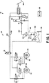
第1の車輪ブレーキ14及び第2の車輪ブレーキ16に連結された作動部分12を有する車両のためのブレーキシステム10の一部が、図1に示されている。第1の車輪ブレーキ14及び第2の車輪ブレーキ16はそれぞれ、車両のECU(Electronic Control Unit )20に情報を送る速度センサ18,18′及びアンチロック機能を発揮させる種々のソレノイド弁17,18及び17′,18′を有している。加えて、ソレノイド19が、ブレーキブースタ34からの供給導管内に設けられ、作動導管が、アキュムレータ24に連結されている。ソレノイド19は、ECU20からの入力に応答してもっぱらトラクションコントロール機能を実行するようになっている。ポンプ32が、ペダル36に加えられた入力に応答してブレーキを働かせるために加圧流体をアキュムレータ24及びブレーキブースタ34に送る。アキュムレータ24とブレーキブースタ34との間に設けられた供給導管40に連結されている圧力スイッチ38が、ECU20に接続されている。圧力スイッチ38からの信号が、ポンプ32の動作を制御して加圧流体を生じさせ、この加圧流体は、可撓性導管52を介して供給導管40及びアキュムレータ24に送られる。アキュムレータ24を所望の流体圧レベルまで充填すると、圧力スイッチ38は、信号をECU20に送り、ポンプ32と関連したモータ30をオフ(作動停止)モードに切り替える。アキュムレータ24がいったん充填されると、可撓性導管52を高圧にさらし続けないようにするために、弁60は、可撓性導管52内の流体を導管53を介してポンプ32のリザーバ33に送ることができる。
【0008】
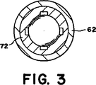
より具体的に詳細に説明すると、図2に示すような弁60は、第1のボア64が設けられたハウジング62を有している。ハウジング62は、導管31によりポンプ32に連結された入口ポート66、可撓性導管52によりアキュムレータ24に連結された出口ポート68及び導管29によりリザーバ33に連結された排出ポート70を有している。スリーブ72が、ボア64内に設けられていて、このスリーブは、第1の端部76から第2の端部78まで延びる第2のボア74を有している。第2のボア74は、第1の肩84により第1の端直径部82から分離されると共に第2の肩88により第2の端直径部86から分離された中央直径部80を有している。スリーブ72は、複数のランド83,83′・・・83n によって分離された対応関係にある複数の軸方向スロット81,81′・・・81n を有し、これらランドは、第1の端部76から肩84まで延びて第1の直径部82を構成している(図3参照)。第1のボール90が、第1の直径部82内に設けられ、この第1のボールは、ランド83,83′・・・83n によって、肩84により構成された充填受座84′と軸方向に整列した状態に保たれている。ボア74の第1の直径部82内に保持された第1のばね93が、第1のボール90に作用し、これを充填受座84に向かって押圧してボア64内に充填室91を構成する。
【0009】
スリーブ72は、第2の直径部86をボア64に連結する複数の半径方向通路85,85′及び第2の端部78に隣接して設けられた第2の肩87を有している。第2のボール92が、第2の直径部86内に設けられていて、端部78を球の一部の形に丸めることにより形成されたフランジ79によってこの中に保持されている。
【0010】
図4に最もよく示されているような3角形の形をしたリンク機構又は部材94が、中央直径部80内に設けられていて、第1の端部96及び第2の端部98を有している。第1の端部96は、第1のボール90に係合し、第2の端部98は第2のボール92に係合している。第1の端部96から第2の端部98までのリンク部材94の長さは、ボール90を充填受座84′に着座させた状態で、第2のボール92が、スリーブ72の端部78を越えて延びるようなものである。
【0011】
ボア64内に設けられた第2のばね又はリターンスプリング100が、スリーブ72の肩87に作用し、スリーブ72を充填室91及び入口ポート60に向かって押圧している。
【0012】
〔動作原理〕
車両が動作中であって、アキュムレータの圧力スイッチ38が、アキュムレータ24内の流体圧が所望レベルよりも低いという指示をECU20に送ると、ECU20は、動作信号をモータ30に送ってポンプ32を作動させる。ポンプ32の作動により、流体は、導管31を通り入口ポート60を経て弁60内の充填室91に流れる。充填室91内の流体圧が、スリーブの端部76に加わる力を生じさせるのに十分な所定量に達してばね100に打ち勝つと、スリーブ72は、排出ポート70に向かって動くことになる。スリーブ72の端部78が排出ポート72に近づくと、ボール92は先ず最初に排出受座70′に係合し、排出ポート70を介する排出室96とリザーバ33との連通を遮断する(図5参照)。ばね100がさらに圧縮されると、ボール92及びボール90は、静止状態に保持され、スリーブ72は引き続き排出室69に向かって動き、充填受座84′が、流体の計量された流れを第2のボア74内に通し、中央直径部80、半径方向通路85,85′、排出室69、出口ポート68及び可撓性導管52を経てアキュムレータ24に分配できるようにする。流体は引き続きアキュムレータ24に流れ、ついには所望の流体圧が達成されるようになり、しかる後、圧力スイッチ38は、アキュムレータ24が完全に充填されたことを表す信号をECU20に送る。しかる後、ECU20は、モータ30への動作信号を停止し、ポンプ32は空転状態になる。
【0013】
ポンプ32からの流体の流れがない場合、充填室91内の流体圧と排出室69内の流体圧が等しくなり、その後、ばね100はスリーブ72を充填室91に向かって移動させる。充填室91内の圧力と排出室69内の圧力が互いに実質的に等しい場合、ばね100は、スリーブ72に作用してスリーブを充填室91に向かって移動させる。充填室に向かうスリーブ72の初期運動により、充填受座84′が動いてボール90に係合し、それにより充填室91から第2のボア74への流通を遮断する。スリーブが更に充填室91に向かって移動すると、フランジ79がボール92に係合してボール92を動かし、これを排出ポート70′から離すので流体がリザーバ33に流れることができる。
【0014】
可撓性導管52と導管40との間には逆止弁41が設けられ、この逆止弁は、流体がアキュムレータ24から弁60に向かって流れることがないようにする。可撓性導管52からの流体の流れは引き続き生じていて、ついにはこの導管内の圧力レベルが、ばね100の力によって定められる値になる。同様に、導管31内には逆止弁51が設けられており、この逆止弁は、充填室91内の流体圧がポンプ32に戻る流体の流れによって散逸しないようにする。
【図面の簡単な説明】
【図1】 本発明に従ってアキュムレータを充填し、可撓性導管を排出する弁を備えたトラクション制御装置付きアンチロックブレーキシステムを有するブレーキシステムの略図である。
【図2】 出口ポートがリザーバへの連通を可能にするために排出ポートに連結された状態の図1の弁の断面図である。
【図3】 図2の3−3線矢視断面図である。
【図4】 図2の4−4線矢視断面図である。
【図5】 入口ポートが、アキュムレータへの連通を可能にするよう出口ポートに連結された状態の図1の弁の断面図である。[0001]
The present invention relates to a valve that allows fluid to flow from a source to fill an accumulator of a brake system and to allow fluid to flow from a conduit to a reservoir when there is no fluid flow from the source.
[0002]
BACKGROUND OF THE INVENTION
In a brake system, it is customary to have a traction control function as well as an antilock brake function. The traction control function utilizes many of the components necessary to achieve the antilock brake function. However, in order for the traction control function to achieve a desired operation level, an accumulator is often provided in the brake system. The accumulator is filled to the desired pressure level by actuation of a pump provided in the brake system. When filling the accumulator, fluid is pumped from the pump through the flexible conduit. Unfortunately, the fluid pressure generated by the pump to fill the accumulator is maintained in the conduit after the pump has been deactivated, so that under certain conditions, the flexibility of the fluid There is a risk of leakage in the conduit. In order to reduce the fluid pressure in the conduit, it has been proposed to permanently connect the flexible conduit to the reservoir via a restriction orifice. This permanent connection allows fluid pressure in the conduit to bleed to reservoir pressure over time. Unfortunately, due to this permanent connection, some of the fluid sent by the pump to the accumulator also flows to the reservoir during the filling operation, which results in a decrease in pump efficiency due to this flow to the reservoir.
[0003]
[Summary of the Invention]
In order to utilize the full capacity of the pump to fill the accumulator, the present invention allows the entire pump output to flow to the accumulator during filling operation and when the fluid from the pump is stopped, after which the fluid is flexible. A valve is provided that allows flow from the conduit to the reservoir. The valve has a housing which has a bore connected to the pump via an inlet port, to an accumulator via an outlet port, and to a reservoir via a discharge port. A sleeve provided in the first bore has a first end located adjacent to the inlet port and a second end located adjacent to the discharge port. A second bore provided in the sleeve and extending from the first end to the second end is separated from the first end diameter by the first shoulder and is second by the second shoulder. And a central diameter portion separated from the end diameter portion of the. A first ball provided in the first end diameter portion is pressed toward the first shoulder by the first spring. A flange provided at the second end of the sleeve holds the second ball within the second diameter of the sleeve. A link mechanism provided in the central diameter portion has a first end that engages with the first ball and a second end that engages with the second ball. A second spring provided in the first bore may press the sleeve toward the inlet port, thereby causing the first spring to seat the first ball on the first shoulder. . With the first ball seated, fluid communication through the central diameter is blocked, but fluid in the conduit can flow to the reservoir, allowing free communication between the outlet port and the discharge port. It can be so. When the pump is activated, the fluid flow is directed to the inlet port. The pressure of the fluid applied to the inlet port creates a filling force that acts on the first end of the sleeve and overcomes the second spring and then first moves the sleeve toward the discharge port. Let As the sleeve approaches the discharge port, the second ball first engages a discharge receptacle provided around the discharge port. When the second ball engages the seat, fluid flow from the first bore to the reservoir is blocked. Further movement of the sleeve occurs when the second spring is compressed, but the second ball remains in a stationary position on the discharge seat and is connected to the second ball by a linkage. The one ball also remains stationary when the first spring is compressed, and the first shoulder fill seat moves away from the first ball and fluid flows to the accumulator through the second bore and discharge port. To be able to. Filling the accumulator stops fluid flow through the second bore, equalizing the fluid pressure applied to both ends of the sleeve, causing the second spring to move the sleeve toward the inlet port and filling the first ball again When seated in the seat, communication between the outlet port and the discharge port is started again.
[0004]
The advantages of the present invention are obtained by limiting the time that the flexible conduit is under high pressure.
[0005]
It is an object of the present invention to provide a valve for filling an accumulator and utilizing the full capacity of the pump while bleeding the flexible conduit when the accumulator is filled, thereby limiting the exposure of the conduit to high pressure. There is.
[0006]
Another advantage of the present invention is that the valve sequentially closes the fluid communication path between the outlet port and the outlet port, but opens the communication path between the inlet port and the outlet port to supply pressurized fluid to the accumulator. There is.
[0007]
[Detailed explanation]
A portion of a
[0008]
More specifically, the valve 60 as shown in FIG. 2 has a
[0009]
The
[0010]
A triangular shaped linkage or
[0011]
A second spring or
[0012]
〔Operating principle〕
When the vehicle is in operation and the accumulator pressure switch 38 sends an instruction to the
[0013]
When there is no fluid flow from the
[0014]
A check valve 41 is provided between the
[Brief description of the drawings]
FIG. 1 is a schematic diagram of a brake system having an anti-lock brake system with a traction control device with a valve that fills an accumulator and discharges a flexible conduit in accordance with the present invention.
2 is a cross-sectional view of the valve of FIG. 1 with the outlet port connected to the drain port to allow communication to the reservoir.
3 is a cross-sectional view taken along line 3-3 in FIG.
4 is a cross-sectional view taken along line 4-4 of FIG.
FIG. 5 is a cross-sectional view of the valve of FIG. 1 with an inlet port coupled to the outlet port to allow communication to an accumulator.
Claims (4)
前記スリーブは、前記第1の端部(76)から前記第1の肩(84)まで延びる複数のランド(83,83’・・・ 83n)によって分離された対応関係にある複数の軸方向スロット(81,81’・・・ 81n)を有し、前記第1のボール(90)は、前記複数のランド(83,83’・・・ 83n)によって前記第2のボア(74)と整列し、他方、前記複数の軸方向スロット(81,81’・・・ 81n)は流体を前記中央直径部(80)に自由に流通させることができる、
請求項1記載の弁。The sleeve (72) couples the second end diameter (86) to the first bore (64) to allow fluid to freely flow to the outlet port ( 68 ). With radial passage (85,85 '),
The sleeve has a plurality of axial slots in corresponding relationship separated by a plurality of lands (83, 83 '... 83n) extending from the first end (76) to the first shoulder (84). (81, 81 ′... 81n), and the first ball (90) is aligned with the second bore (74) by the plurality of lands (83, 83 ′... 83n). On the other hand, the plurality of axial slots (81, 81 ′... 81n) can freely circulate fluid to the central diameter portion (80).
The valve according to claim 1.
請求項2記載の弁。When there is no fluid flow from the fluid source (32) through the inlet port ( 66 ), the fluid pressure acting on the first end (76) of the sleeve (72) and the sleeve (72) The fluid pressures acting on the second end (78) are equal to each other, after which the second spring (100) moves the sleeve (72) away from the discharge port (70) and the central diameter. The communication through the section (80) is blocked, but the outlet port (68) and the discharge port (70) are allowed to communicate and fluid flows from the conduit (52) to the reservoir (33), thereby , The pressure of the fluid in the conduit (52) can be reduced,
The valve according to claim 2.
Applications Claiming Priority (3)
| Application Number | Priority Date | Filing Date | Title |
|---|---|---|---|
| US09/372,130 US6173730B1 (en) | 1999-08-11 | 1999-08-11 | Charging and bleed value |
| US09/372,130 | 1999-08-11 | ||
| PCT/US2000/020980 WO2001010696A1 (en) | 1999-08-11 | 2000-08-01 | Charging and bleed valve |
Publications (3)
| Publication Number | Publication Date |
|---|---|
| JP2003506262A JP2003506262A (en) | 2003-02-18 |
| JP2003506262A5 JP2003506262A5 (en) | 2007-10-11 |
| JP4838960B2 true JP4838960B2 (en) | 2011-12-14 |
Family
ID=23466834
Family Applications (1)
| Application Number | Title | Priority Date | Filing Date |
|---|---|---|---|
| JP2001515181A Expired - Fee Related JP4838960B2 (en) | 1999-08-11 | 2000-08-01 | Filling and bleed valve |
Country Status (5)
| Country | Link |
|---|---|
| US (1) | US6173730B1 (en) |
| EP (1) | EP1119480B1 (en) |
| JP (1) | JP4838960B2 (en) |
| DE (1) | DE60027399T2 (en) |
| WO (1) | WO2001010696A1 (en) |
Families Citing this family (2)
| Publication number | Priority date | Publication date | Assignee | Title |
|---|---|---|---|---|
| US7367636B2 (en) * | 2005-02-16 | 2008-05-06 | Bendix Commercial Vehicle Systems, Llc | Solenoid armature with integrated spherical soft seal |
| US11738732B2 (en) * | 2021-04-28 | 2023-08-29 | Caterpillar Inc. | Automatic retarding control system |
Citations (5)
| Publication number | Priority date | Publication date | Assignee | Title |
|---|---|---|---|---|
| JPS5376424A (en) * | 1976-12-17 | 1978-07-06 | Bosch Gmbh Robert | Electroomagnetic type valve device |
| JPS54135982A (en) * | 1978-04-01 | 1979-10-22 | Teves Gmbh Alfred | Reserve feeder for discharging pressure fluid to user*s section |
| JPS62181954A (en) * | 1986-02-05 | 1987-08-10 | Toyota Motor Corp | Hydraulic braking device for automobile |
| JPS62297574A (en) * | 1986-04-25 | 1987-12-24 | シ−ルド・パワ−・コ−ポレ−シヨン | Electrohydraulic type valve |
| JPH0243579A (en) * | 1988-08-03 | 1990-02-14 | Nec Corp | Printing device |
Family Cites Families (7)
| Publication number | Priority date | Publication date | Assignee | Title |
|---|---|---|---|---|
| GB806972A (en) * | 1954-08-26 | 1959-01-07 | Boulton Aircraft Ltd | Improvements in bleeder valves |
| US3604446A (en) * | 1969-05-26 | 1971-09-14 | Garrett Corp | Valve |
| US3845776A (en) * | 1971-12-24 | 1974-11-05 | Aisin Seiki | Unloader valve |
| JPS49106020A (en) * | 1973-02-13 | 1974-10-08 | ||
| US3896845A (en) * | 1974-06-13 | 1975-07-29 | Gen Motors Corp | Accumulator charging and relief valve |
| DE3218344A1 (en) * | 1982-05-14 | 1983-11-17 | Lucas Industries P.L.C., Birmingham, West Midlands | Accumulator-loading valve |
| JPH0243579U (en) * | 1988-09-20 | 1990-03-26 |
-
1999
- 1999-08-11 US US09/372,130 patent/US6173730B1/en not_active Expired - Lifetime
-
2000
- 2000-08-01 JP JP2001515181A patent/JP4838960B2/en not_active Expired - Fee Related
- 2000-08-01 WO PCT/US2000/020980 patent/WO2001010696A1/en active IP Right Grant
- 2000-08-01 EP EP00952370A patent/EP1119480B1/en not_active Expired - Lifetime
- 2000-08-01 DE DE2000627399 patent/DE60027399T2/en not_active Expired - Lifetime
Patent Citations (5)
| Publication number | Priority date | Publication date | Assignee | Title |
|---|---|---|---|---|
| JPS5376424A (en) * | 1976-12-17 | 1978-07-06 | Bosch Gmbh Robert | Electroomagnetic type valve device |
| JPS54135982A (en) * | 1978-04-01 | 1979-10-22 | Teves Gmbh Alfred | Reserve feeder for discharging pressure fluid to user*s section |
| JPS62181954A (en) * | 1986-02-05 | 1987-08-10 | Toyota Motor Corp | Hydraulic braking device for automobile |
| JPS62297574A (en) * | 1986-04-25 | 1987-12-24 | シ−ルド・パワ−・コ−ポレ−シヨン | Electrohydraulic type valve |
| JPH0243579A (en) * | 1988-08-03 | 1990-02-14 | Nec Corp | Printing device |
Also Published As
| Publication number | Publication date |
|---|---|
| EP1119480B1 (en) | 2006-04-19 |
| JP2003506262A (en) | 2003-02-18 |
| EP1119480A1 (en) | 2001-08-01 |
| DE60027399T2 (en) | 2007-02-01 |
| DE60027399D1 (en) | 2006-05-24 |
| WO2001010696A1 (en) | 2001-02-15 |
| US6173730B1 (en) | 2001-01-16 |
Similar Documents
| Publication | Publication Date | Title |
|---|---|---|
| JP4275315B2 (en) | Master cylinder for electro-hydraulic brake equipment for automobiles | |
| US7419227B2 (en) | Braking device for a motor vehicle | |
| JP4066721B2 (en) | Check valve and brake actuator using the check valve | |
| US6789857B2 (en) | Vehicle brake hydraulic pressure generator | |
| CN112292295B (en) | Hydraulic control unit for saddle-ride type vehicle brake system, and saddle-ride type vehicle brake system | |
| JP3867498B2 (en) | Check valve and ABS actuator using the check valve | |
| US20220176928A1 (en) | Electronic brake system | |
| CN100372713C (en) | Brake control system | |
| JP4003784B2 (en) | Brake device for vehicle | |
| CN112601682A (en) | Brake-by-wire system having at least one brake circuit, method for operating a brake system, and diagnostic valve for such a brake system | |
| JP4838960B2 (en) | Filling and bleed valve | |
| US5330259A (en) | Electrohydraulic braking system with remote booster | |
| US5487597A (en) | Hydraulic circuit with a capacity forming a distributor | |
| US6312062B1 (en) | Brake fluid pressure control device | |
| CN114667245B (en) | Valve device | |
| JPH02293246A (en) | Hydraulic brake | |
| KR20000013677A (en) | Device for power distributing of brake for motor vehicle | |
| JP3769774B2 (en) | Hydraulic brake device for vehicles | |
| US6038857A (en) | Control apparatus for a brake booster | |
| JP3026715U (en) | Hydraulic pressure control device | |
| JPH05254422A (en) | Braking device for vehicle | |
| JP2000309263A (en) | Braking device having a plurality of operating sources | |
| JPS6181260A (en) | Hydro booster for anti-skid system | |
| JPH03503750A (en) | anti-lock hydraulic brake system | |
| SU918141A2 (en) | Motor vehicle brake hydraulic actuator |
Legal Events
| Date | Code | Title | Description |
|---|---|---|---|
| A521 | Written amendment |
Free format text: JAPANESE INTERMEDIATE CODE: A523 Effective date: 20070801 |
|
| A621 | Written request for application examination |
Free format text: JAPANESE INTERMEDIATE CODE: A621 Effective date: 20070801 |
|
| A977 | Report on retrieval |
Free format text: JAPANESE INTERMEDIATE CODE: A971007 Effective date: 20101025 |
|
| A131 | Notification of reasons for refusal |
Free format text: JAPANESE INTERMEDIATE CODE: A131 Effective date: 20101111 |
|
| A521 | Written amendment |
Free format text: JAPANESE INTERMEDIATE CODE: A523 Effective date: 20110210 |
|
| TRDD | Decision of grant or rejection written | ||
| A01 | Written decision to grant a patent or to grant a registration (utility model) |
Free format text: JAPANESE INTERMEDIATE CODE: A01 Effective date: 20110901 |
|
| A01 | Written decision to grant a patent or to grant a registration (utility model) |
Free format text: JAPANESE INTERMEDIATE CODE: A01 |
|
| A61 | First payment of annual fees (during grant procedure) |
Free format text: JAPANESE INTERMEDIATE CODE: A61 Effective date: 20111003 |
|
| FPAY | Renewal fee payment (event date is renewal date of database) |
Free format text: PAYMENT UNTIL: 20141007 Year of fee payment: 3 |
|
| R150 | Certificate of patent or registration of utility model |
Free format text: JAPANESE INTERMEDIATE CODE: R150 |
|
| R250 | Receipt of annual fees |
Free format text: JAPANESE INTERMEDIATE CODE: R250 |
|
| R250 | Receipt of annual fees |
Free format text: JAPANESE INTERMEDIATE CODE: R250 |
|
| R250 | Receipt of annual fees |
Free format text: JAPANESE INTERMEDIATE CODE: R250 |
|
| LAPS | Cancellation because of no payment of annual fees |