EP1119480B1 - Charging and bleed valve - Google Patents
Charging and bleed valve Download PDFInfo
- Publication number
- EP1119480B1 EP1119480B1 EP00952370A EP00952370A EP1119480B1 EP 1119480 B1 EP1119480 B1 EP 1119480B1 EP 00952370 A EP00952370 A EP 00952370A EP 00952370 A EP00952370 A EP 00952370A EP 1119480 B1 EP1119480 B1 EP 1119480B1
- Authority
- EP
- European Patent Office
- Prior art keywords
- fluid
- sleeve
- diameter section
- ball
- bore
- Prior art date
- Legal status (The legal status is an assumption and is not a legal conclusion. Google has not performed a legal analysis and makes no representation as to the accuracy of the status listed.)
- Expired - Lifetime
Links
Images

Classifications
-
- B—PERFORMING OPERATIONS; TRANSPORTING
- B60—VEHICLES IN GENERAL
- B60T—VEHICLE BRAKE CONTROL SYSTEMS OR PARTS THEREOF; BRAKE CONTROL SYSTEMS OR PARTS THEREOF, IN GENERAL; ARRANGEMENT OF BRAKING ELEMENTS ON VEHICLES IN GENERAL; PORTABLE DEVICES FOR PREVENTING UNWANTED MOVEMENT OF VEHICLES; VEHICLE MODIFICATIONS TO FACILITATE COOLING OF BRAKES
- B60T17/00—Component parts, details, or accessories of power brake systems not covered by groups B60T8/00, B60T13/00 or B60T15/00, or presenting other characteristic features
- B60T17/02—Arrangements of pumps or compressors, or control devices therefor
-
- B—PERFORMING OPERATIONS; TRANSPORTING
- B60—VEHICLES IN GENERAL
- B60T—VEHICLE BRAKE CONTROL SYSTEMS OR PARTS THEREOF; BRAKE CONTROL SYSTEMS OR PARTS THEREOF, IN GENERAL; ARRANGEMENT OF BRAKING ELEMENTS ON VEHICLES IN GENERAL; PORTABLE DEVICES FOR PREVENTING UNWANTED MOVEMENT OF VEHICLES; VEHICLE MODIFICATIONS TO FACILITATE COOLING OF BRAKES
- B60T13/00—Transmitting braking action from initiating means to ultimate brake actuator with power assistance or drive; Brake systems incorporating such transmitting means, e.g. air-pressure brake systems
- B60T13/10—Transmitting braking action from initiating means to ultimate brake actuator with power assistance or drive; Brake systems incorporating such transmitting means, e.g. air-pressure brake systems with fluid assistance, drive, or release
- B60T13/12—Transmitting braking action from initiating means to ultimate brake actuator with power assistance or drive; Brake systems incorporating such transmitting means, e.g. air-pressure brake systems with fluid assistance, drive, or release the fluid being liquid
- B60T13/14—Transmitting braking action from initiating means to ultimate brake actuator with power assistance or drive; Brake systems incorporating such transmitting means, e.g. air-pressure brake systems with fluid assistance, drive, or release the fluid being liquid using accumulators or reservoirs fed by pumps
- B60T13/148—Arrangements for pressure supply
-
- B—PERFORMING OPERATIONS; TRANSPORTING
- B60—VEHICLES IN GENERAL
- B60T—VEHICLE BRAKE CONTROL SYSTEMS OR PARTS THEREOF; BRAKE CONTROL SYSTEMS OR PARTS THEREOF, IN GENERAL; ARRANGEMENT OF BRAKING ELEMENTS ON VEHICLES IN GENERAL; PORTABLE DEVICES FOR PREVENTING UNWANTED MOVEMENT OF VEHICLES; VEHICLE MODIFICATIONS TO FACILITATE COOLING OF BRAKES
- B60T13/00—Transmitting braking action from initiating means to ultimate brake actuator with power assistance or drive; Brake systems incorporating such transmitting means, e.g. air-pressure brake systems
- B60T13/10—Transmitting braking action from initiating means to ultimate brake actuator with power assistance or drive; Brake systems incorporating such transmitting means, e.g. air-pressure brake systems with fluid assistance, drive, or release
- B60T13/12—Transmitting braking action from initiating means to ultimate brake actuator with power assistance or drive; Brake systems incorporating such transmitting means, e.g. air-pressure brake systems with fluid assistance, drive, or release the fluid being liquid
- B60T13/16—Transmitting braking action from initiating means to ultimate brake actuator with power assistance or drive; Brake systems incorporating such transmitting means, e.g. air-pressure brake systems with fluid assistance, drive, or release the fluid being liquid using pumps directly, i.e. without interposition of accumulators or reservoirs
- B60T13/168—Arrangements for pressure supply
-
- B—PERFORMING OPERATIONS; TRANSPORTING
- B60—VEHICLES IN GENERAL
- B60T—VEHICLE BRAKE CONTROL SYSTEMS OR PARTS THEREOF; BRAKE CONTROL SYSTEMS OR PARTS THEREOF, IN GENERAL; ARRANGEMENT OF BRAKING ELEMENTS ON VEHICLES IN GENERAL; PORTABLE DEVICES FOR PREVENTING UNWANTED MOVEMENT OF VEHICLES; VEHICLE MODIFICATIONS TO FACILITATE COOLING OF BRAKES
- B60T8/00—Arrangements for adjusting wheel-braking force to meet varying vehicular or ground-surface conditions, e.g. limiting or varying distribution of braking force
- B60T8/32—Arrangements for adjusting wheel-braking force to meet varying vehicular or ground-surface conditions, e.g. limiting or varying distribution of braking force responsive to a speed condition, e.g. acceleration or deceleration
- B60T8/34—Arrangements for adjusting wheel-braking force to meet varying vehicular or ground-surface conditions, e.g. limiting or varying distribution of braking force responsive to a speed condition, e.g. acceleration or deceleration having a fluid pressure regulator responsive to a speed condition
- B60T8/40—Arrangements for adjusting wheel-braking force to meet varying vehicular or ground-surface conditions, e.g. limiting or varying distribution of braking force responsive to a speed condition, e.g. acceleration or deceleration having a fluid pressure regulator responsive to a speed condition comprising an additional fluid circuit including fluid pressurising means for modifying the pressure of the braking fluid, e.g. including wheel driven pumps for detecting a speed condition, or pumps which are controlled by means independent of the braking system
- B60T8/404—Control of the pump unit
- B60T8/4054—Control of the pump unit involving the delivery pressure control
-
- B—PERFORMING OPERATIONS; TRANSPORTING
- B60—VEHICLES IN GENERAL
- B60T—VEHICLE BRAKE CONTROL SYSTEMS OR PARTS THEREOF; BRAKE CONTROL SYSTEMS OR PARTS THEREOF, IN GENERAL; ARRANGEMENT OF BRAKING ELEMENTS ON VEHICLES IN GENERAL; PORTABLE DEVICES FOR PREVENTING UNWANTED MOVEMENT OF VEHICLES; VEHICLE MODIFICATIONS TO FACILITATE COOLING OF BRAKES
- B60T8/00—Arrangements for adjusting wheel-braking force to meet varying vehicular or ground-surface conditions, e.g. limiting or varying distribution of braking force
- B60T8/32—Arrangements for adjusting wheel-braking force to meet varying vehicular or ground-surface conditions, e.g. limiting or varying distribution of braking force responsive to a speed condition, e.g. acceleration or deceleration
- B60T8/34—Arrangements for adjusting wheel-braking force to meet varying vehicular or ground-surface conditions, e.g. limiting or varying distribution of braking force responsive to a speed condition, e.g. acceleration or deceleration having a fluid pressure regulator responsive to a speed condition
- B60T8/40—Arrangements for adjusting wheel-braking force to meet varying vehicular or ground-surface conditions, e.g. limiting or varying distribution of braking force responsive to a speed condition, e.g. acceleration or deceleration having a fluid pressure regulator responsive to a speed condition comprising an additional fluid circuit including fluid pressurising means for modifying the pressure of the braking fluid, e.g. including wheel driven pumps for detecting a speed condition, or pumps which are controlled by means independent of the braking system
- B60T8/4072—Systems in which a driver input signal is used as a control signal for the additional fluid circuit which is normally used for braking
-
- B—PERFORMING OPERATIONS; TRANSPORTING
- B60—VEHICLES IN GENERAL
- B60T—VEHICLE BRAKE CONTROL SYSTEMS OR PARTS THEREOF; BRAKE CONTROL SYSTEMS OR PARTS THEREOF, IN GENERAL; ARRANGEMENT OF BRAKING ELEMENTS ON VEHICLES IN GENERAL; PORTABLE DEVICES FOR PREVENTING UNWANTED MOVEMENT OF VEHICLES; VEHICLE MODIFICATIONS TO FACILITATE COOLING OF BRAKES
- B60T8/00—Arrangements for adjusting wheel-braking force to meet varying vehicular or ground-surface conditions, e.g. limiting or varying distribution of braking force
- B60T8/32—Arrangements for adjusting wheel-braking force to meet varying vehicular or ground-surface conditions, e.g. limiting or varying distribution of braking force responsive to a speed condition, e.g. acceleration or deceleration
- B60T8/34—Arrangements for adjusting wheel-braking force to meet varying vehicular or ground-surface conditions, e.g. limiting or varying distribution of braking force responsive to a speed condition, e.g. acceleration or deceleration having a fluid pressure regulator responsive to a speed condition
- B60T8/48—Arrangements for adjusting wheel-braking force to meet varying vehicular or ground-surface conditions, e.g. limiting or varying distribution of braking force responsive to a speed condition, e.g. acceleration or deceleration having a fluid pressure regulator responsive to a speed condition connecting the brake actuator to an alternative or additional source of fluid pressure, e.g. traction control systems
- B60T8/4809—Traction control, stability control, using both the wheel brakes and other automatic braking systems
- B60T8/4827—Traction control, stability control, using both the wheel brakes and other automatic braking systems in hydraulic brake systems
-
- B—PERFORMING OPERATIONS; TRANSPORTING
- B60—VEHICLES IN GENERAL
- B60T—VEHICLE BRAKE CONTROL SYSTEMS OR PARTS THEREOF; BRAKE CONTROL SYSTEMS OR PARTS THEREOF, IN GENERAL; ARRANGEMENT OF BRAKING ELEMENTS ON VEHICLES IN GENERAL; PORTABLE DEVICES FOR PREVENTING UNWANTED MOVEMENT OF VEHICLES; VEHICLE MODIFICATIONS TO FACILITATE COOLING OF BRAKES
- B60T8/00—Arrangements for adjusting wheel-braking force to meet varying vehicular or ground-surface conditions, e.g. limiting or varying distribution of braking force
- B60T8/32—Arrangements for adjusting wheel-braking force to meet varying vehicular or ground-surface conditions, e.g. limiting or varying distribution of braking force responsive to a speed condition, e.g. acceleration or deceleration
- B60T8/34—Arrangements for adjusting wheel-braking force to meet varying vehicular or ground-surface conditions, e.g. limiting or varying distribution of braking force responsive to a speed condition, e.g. acceleration or deceleration having a fluid pressure regulator responsive to a speed condition
- B60T8/341—Systems characterised by their valves
-
- Y—GENERAL TAGGING OF NEW TECHNOLOGICAL DEVELOPMENTS; GENERAL TAGGING OF CROSS-SECTIONAL TECHNOLOGIES SPANNING OVER SEVERAL SECTIONS OF THE IPC; TECHNICAL SUBJECTS COVERED BY FORMER USPC CROSS-REFERENCE ART COLLECTIONS [XRACs] AND DIGESTS
- Y10—TECHNICAL SUBJECTS COVERED BY FORMER USPC
- Y10T—TECHNICAL SUBJECTS COVERED BY FORMER US CLASSIFICATION
- Y10T137/00—Fluid handling
- Y10T137/2496—Self-proportioning or correlating systems
- Y10T137/2559—Self-controlled branched flow systems
- Y10T137/2574—Bypass or relief controlled by main line fluid condition
- Y10T137/2605—Pressure responsive
- Y10T137/2612—Common sensor for both bypass or relief valve and other branch valve
- Y10T137/2615—Bypass or relief valve opens as other branch valve closes
-
- Y—GENERAL TAGGING OF NEW TECHNOLOGICAL DEVELOPMENTS; GENERAL TAGGING OF CROSS-SECTIONAL TECHNOLOGIES SPANNING OVER SEVERAL SECTIONS OF THE IPC; TECHNICAL SUBJECTS COVERED BY FORMER USPC CROSS-REFERENCE ART COLLECTIONS [XRACs] AND DIGESTS
- Y10—TECHNICAL SUBJECTS COVERED BY FORMER USPC
- Y10T—TECHNICAL SUBJECTS COVERED BY FORMER US CLASSIFICATION
- Y10T137/00—Fluid handling
- Y10T137/2496—Self-proportioning or correlating systems
- Y10T137/2559—Self-controlled branched flow systems
- Y10T137/2574—Bypass or relief controlled by main line fluid condition
- Y10T137/2605—Pressure responsive
- Y10T137/2617—Bypass or relief valve biased open
-
- Y—GENERAL TAGGING OF NEW TECHNOLOGICAL DEVELOPMENTS; GENERAL TAGGING OF CROSS-SECTIONAL TECHNOLOGIES SPANNING OVER SEVERAL SECTIONS OF THE IPC; TECHNICAL SUBJECTS COVERED BY FORMER USPC CROSS-REFERENCE ART COLLECTIONS [XRACs] AND DIGESTS
- Y10—TECHNICAL SUBJECTS COVERED BY FORMER USPC
- Y10T—TECHNICAL SUBJECTS COVERED BY FORMER US CLASSIFICATION
- Y10T137/00—Fluid handling
- Y10T137/2496—Self-proportioning or correlating systems
- Y10T137/2559—Self-controlled branched flow systems
- Y10T137/2574—Bypass or relief controlled by main line fluid condition
- Y10T137/2605—Pressure responsive
- Y10T137/2622—Bypass or relief valve responsive to pressure downstream of outlet valve
- Y10T137/2627—Outlet valve carried by bypass or relief valve
Definitions
- This invention relates to a valve through which fluid flows from a source to charge an accumulator in a brake system and which allows fluid to flow from the conduit to a reservoir in the absence of flow of fluid from the source, according to the preamble of claim 1.
- Document DE 3 218 344 discloses such a valve.
- a traction control function In brakes systems it has become a common practice to include a traction control function along with anti-lock brake capabilities.
- the traction control function utilizes may of the components necessary to achieve the anti-lock brake capabilities.
- an accumulator is often included in the brake system.
- the accumulator is charged to a desired pressure level by the operation of a pump in the brake system.
- In charging the accumulator fluid is communicated from the pump through a flexible conduit.
- the fluid pressure developed by the pump to charge the accumulator is maintained in the conduit even after the pump has been turned off and as a result after a period of time and under some conditions it is possible that a leak may occur in the flexible conduit.
- the flexible conduit be permanently connected to a reservoir through a restricted orifice.
- This permanent connection allows the fluid pressure in the conduit to bleed to reservoir pressure over a period of time.
- this permanent connection also allows a portion of the fluid supplied to the accumulator by the pump to flow to the reservoir during the charging function and as a result the efficiency of the pump is reduced by this flow to the reservoir.
- the present invention has a valve which allows the entire output of a pump to flow to an accumulator during a charging operation and when the flow from the pump terminates thereafter allows fluid to flow from a flexible conduit to a reservoir.
- the valve has a housing with a first bore therein connected to the pump through an entrance port, to the accumulator through an exit port and to the reservoir through an exhaust port.
- a sleeve located in the first bore has a first end adjacent the entrance port and a second end adjacent the exhaust port.
- a second bore in the sleeve which extends from the first end to the second end has a central diameter section separated from a first end diameter section by a first shoulder and from a second end diameter section by a second shoulder.
- a first ball located in the first end diameter section is urged by a first spring toward the first shoulder.
- a flange on the second end of the sleeve retains a second ball in the second diameter section of the sleeve.
- Linkage located in the central diameter section has a first end, which engages the first ball, and a second end, which engages the second ball.
- a second spring located in the first bore urges the sleeve toward the entrance port to allow the first spring to seat the first ball on the first shoulder.
- An advantage of the present invention is provided by limiting the time that a flexible conduit is under high pressure.
- An object of this invention is to provide a valve for charging an accumulator and for bleeding a flexible conduit when the accumulator is charged to utilize a full capacity of a pump while limiting the exposure of a conduit to high pressure.
- a further advantage of this invention resides in a valve, which sequentially closes a flow communication path between an exit port and an exhaust port while opening a communication path between an entrance port and the exit port to supply pressurized fluid to an accumulator.
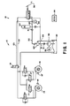
- FIG. 1 A portion of a brake system 10 is illustrated in Figure 1 for a vehicle having an actuation section 12 connected to first 14 and second 16 wheel brakes.
- the first 14 and second 16 wheel brakes each have speed sensors 18,18' which supply information to an ECU 20 for the vehicle and various solenoid valves 17,18 and 17'18' for performing an anti-lock function.
- a solenoid 19 connected in a supply conduit 22 from a brake booster 34 and an actuation conduit connected to an accumulator 24. Solenoid 19 is dedicated to performing a traction control function in responds to an input from the ECU 20.
- a pump 32 supplies the accumulator 24 and the brake booster 34 with pressurized fluid to effect a brake application in response to an input applied to pedal 36.
- a pressure switch 38 connected to a supply conduit 40 between the accumulator 24 and brake booster 34 is connected to the ECU 20. Signals from the pressure switch 38 control the operation of pump 32 for the development of pressurized fluid which is communicated through flexible conduit 52 to the supply conduit 40 and accumulator 24. When accumulator 24 is charged to a desired fluid pressure level, pressure switch 38 communicates a signal to the ECU 20 a motor 30 associated with pump 32 is switched to an off mode. In order that the flexible conduit 52 is not continually exposed to high pressure once accumulator 24 is charged, a valve 60 allows fluid in the flexible conduit 52 to be communicated through conduit 53 to reservoir 33 for pump 32.
- valve 60 as shown in Figure 2 has a housing 62 having a first bore 64 therein.
- Housing 62 has an entrance port 66 connected to pump 32 by a conduit 31, an exit port 68 connected to accumulator 24 by flexible conduit 52 and an exhaust port 70 connected to the reservoir 33 by conduit 29.
- a sleeve 72 is located in bore 64 has a second bore 74 that extends from a first end 76 to a second end 78.
- the second bore 74 has a central diameter section 80 separated from a first end diameter section 82 by a first shoulder 84 and from a second end diameter section 86 by a second shoulder 88.
- the sleeve 72 has a plurality of axial slots 81, 81' ⁇ 81 n separated by a corresponding plurality of lands 83, 83' ⁇ 83 n which extend from said first end 76 to shoulder 84 to define the first diameter section 82, see Figure 3.
- a first ball 90 is located in first diameter section 82 and maintained in axial alignment with a charging seat 84' formed by shoulder 84 by lands 83, 83' ⁇ 83 n .
- a first spring 93 retained in the first diameter section 82 of bore 74 acts on and urges first ball 90 toward charging seat 84 to define a charging chamber 91 within bore 64.
- the sleeve 72 has a plurality of radial passages 85,85' through which the second diameter section 86 is connected with bore 64 and a second shoulder 87 located adjacent the second end 78.
- a second ball 92 is located in second diameter section 86 and retained in therein by a flange 79 formed by rolling end 78 in the shape of a partial sphere.
- a tri-angular shaped linkage 94 as best-illustrated in Figure 4 is located in the central diameter section 80 has a first end 96 and a second end 98.
- the first end 96 engages the first ball 90 and the second end 98 engages the second ball 92.
- the length of the linkage 94 from the first end 96 to the second end 98 is such that with ball 90 seated on charging seat 84' the second ball 92 extends past end 78 of sleeve 72.
- a second or return spring 100 located in bore 64 acts on shoulder 87 of sleeve 72 for urging sleeve 72 toward the charging chamber 91 and entrance port 60.
- spring 100 moves sleeve 72 toward the charging chamber 91.
- spring 100 acts on sleeve 72 to move sleeve toward the charging chamber 91.
- Initial movement of sleeve 72 toward the charging chamber moves charging seat 84' into engagement with ball 90 to interrupt communication from charging chamber 91 to the second bore 74.
- Further movement of sleeve toward the charging chamber 91 brings flange 79 into engagement with ball 92 to move ball 92 off exhaust port 70' and allow fluid to flow to the reservoir 33.
- Check valve 41 located between the flexible conduit 52 and conduit 40 assures that fluid does not flow from the accumulator 24 toward valve 60. Fluid flow from the flexible conduit 52 continues until the pressure level therein is at a value as defined by the force of spring 100. Similarly a check valve 51 in conduit 31 assures that the fluid pressure in charging chamber 91 is not dissipated by the flow of fluid back to pump 32.
Landscapes
- Engineering & Computer Science (AREA)
- Transportation (AREA)
- Mechanical Engineering (AREA)
- Physics & Mathematics (AREA)
- Fluid Mechanics (AREA)
- Check Valves (AREA)
- Valves And Accessory Devices For Braking Systems (AREA)
Description
- This invention relates to a valve through which fluid flows from a source to charge an accumulator in a brake system and which allows fluid to flow from the conduit to a reservoir in the absence of flow of fluid from the source, according to the preamble of claim 1. Document DE 3 218 344 discloses such a valve.
- In brakes systems it has become a common practice to include a traction control function along with anti-lock brake capabilities. The traction control function utilizes may of the components necessary to achieve the anti-lock brake capabilities. However, in order for the traction control function to achieve a desired level of operation, an accumulator is often included in the brake system. The accumulator is charged to a desired pressure level by the operation of a pump in the brake system. In charging the accumulator fluid is communicated from the pump through a flexible conduit. Unfortunately, the fluid pressure developed by the pump to charge the accumulator is maintained in the conduit even after the pump has been turned off and as a result after a period of time and under some conditions it is possible that a leak may occur in the flexible conduit. In order to relieve the fluid pressure in the conduit it has been suggested that the flexible conduit be permanently connected to a reservoir through a restricted orifice. This permanent connection allows the fluid pressure in the conduit to bleed to reservoir pressure over a period of time. Unfortunately this permanent connection also allows a portion of the fluid supplied to the accumulator by the pump to flow to the reservoir during the charging function and as a result the efficiency of the pump is reduced by this flow to the reservoir.
- In order to utilize the full capacity of a pump to charge an accumulator, the present invention has a valve which allows the entire output of a pump to flow to an accumulator during a charging operation and when the flow from the pump terminates thereafter allows fluid to flow from a flexible conduit to a reservoir. The valve has a housing with a first bore therein connected to the pump through an entrance port, to the accumulator through an exit port and to the reservoir through an exhaust port. A sleeve located in the first bore has a first end adjacent the entrance port and a second end adjacent the exhaust port. A second bore in the sleeve which extends from the first end to the second end has a central diameter section separated from a first end diameter section by a first shoulder and from a second end diameter section by a second shoulder. A first ball located in the first end diameter section is urged by a first spring toward the first shoulder. A flange on the second end of the sleeve retains a second ball in the second diameter section of the sleeve. Linkage located in the central diameter section has a first end, which engages the first ball, and a second end, which engages the second ball. A second spring located in the first bore urges the sleeve toward the entrance port to allow the first spring to seat the first ball on the first shoulder. With the first ball seated fluid communication is prevented through the central diameter section while permitting free communication between the exit port and the exhaust port to allow fluid in the conduit to flow to the reservoir. When the pump is activated fluid flow is communicated to the entrance port. The pressure of the fluid presented to the entrance port develops a charging force which acts on the first end of the sleeve and after overcoming the second spring initially moves the sleeve toward the exhaust port. As the sleeve approaches the exhaust port, the second ball is first to engage an exhaust seat surrounding said exhaust port. On engagement of the second ball with the seat fluid communication from the first bore to the reservoir is interrupted. Further movement of the sleeve occurs as the second spring is compressed, however, the second ball remains in a stationary position on the exhaust seat and the first ball which is connected by the linkage to the first ball also remains stationary as the first spring is now compressed with a charging seat of the first shoulder moving away from the first ball to allow fluid to flow to the accumulator by way of the second bore and exhaust port. When the accumulator is charged, flow of fluid through the second bore terminates and the fluid pressure across the sleeve equalizes such that the second spring moves the sleeve toward the entrance port and again initiate communication between the exit port and exhaust ports as the first ball is again seated on the charging seat.
- An advantage of the present invention is provided by limiting the time that a flexible conduit is under high pressure.
- An object of this invention is to provide a valve for charging an accumulator and for bleeding a flexible conduit when the accumulator is charged to utilize a full capacity of a pump while limiting the exposure of a conduit to high pressure.
- A further advantage of this invention resides in a valve, which sequentially closes a flow communication path between an exit port and an exhaust port while opening a communication path between an entrance port and the exit port to supply pressurized fluid to an accumulator.
-
- Figure 1 is a schematic illustration of a brake system having an anti-lock brake system with traction control with a valve to charge an accumulator and exhaust a flexible conduit according to the present invention;
- Figure 2 is a sectional view of the valve of Figure 1 with an exit port connected to an exhaust to provide for communication to a reservoir;
- Figure 3 is a sectional view taken along line 3-3 of Figure 2;
- Figure 4 is a sectional view taken along line 4-4 of Figure 2; and
- Figure 5 is a section view of the valve in Figure 1 with an entrance port connected to the exit port to provide for communication to an accumulator.
- A portion of a
brake system 10 is illustrated in Figure 1 for a vehicle having an actuation section 12 connected to first 14 and second 16 wheel brakes. The first 14 and second 16 wheel brakes each havespeed sensors 18,18' which supply information to anECU 20 for the vehicle andvarious solenoid valves 17,18 and 17'18' for performing an anti-lock function. In addition asolenoid 19 connected in asupply conduit 22 from a brake booster 34 and an actuation conduit connected to anaccumulator 24. Solenoid 19 is dedicated to performing a traction control function in responds to an input from theECU 20. Apump 32 supplies theaccumulator 24 and the brake booster 34 with pressurized fluid to effect a brake application in response to an input applied topedal 36. Apressure switch 38 connected to asupply conduit 40 between theaccumulator 24 and brake booster 34 is connected to theECU 20. Signals from thepressure switch 38 control the operation ofpump 32 for the development of pressurized fluid which is communicated throughflexible conduit 52 to thesupply conduit 40 andaccumulator 24. Whenaccumulator 24 is charged to a desired fluid pressure level,pressure switch 38 communicates a signal to the ECU 20 amotor 30 associated withpump 32 is switched to an off mode. In order that theflexible conduit 52 is not continually exposed to high pressure onceaccumulator 24 is charged, avalve 60 allows fluid in theflexible conduit 52 to be communicated through conduit 53 toreservoir 33 forpump 32. - In more particular detail the
valve 60 as shown in Figure 2 has ahousing 62 having afirst bore 64 therein.Housing 62 has anentrance port 66 connected topump 32 by aconduit 31, anexit port 68 connected toaccumulator 24 byflexible conduit 52 and anexhaust port 70 connected to thereservoir 33 byconduit 29. Asleeve 72 is located inbore 64 has asecond bore 74 that extends from afirst end 76 to asecond end 78. Thesecond bore 74 has acentral diameter section 80 separated from a firstend diameter section 82 by afirst shoulder 84 and from a secondend diameter section 86 by asecond shoulder 88. Thesleeve 72 has a plurality of axial slots 81, 81'···81n separated by a corresponding plurality of lands 83, 83'···83n which extend from saidfirst end 76 toshoulder 84 to define thefirst diameter section 82, see Figure 3. Afirst ball 90 is located infirst diameter section 82 and maintained in axial alignment with a charging seat 84' formed byshoulder 84 by lands 83, 83'···83n . Afirst spring 93 retained in thefirst diameter section 82 ofbore 74 acts on and urgesfirst ball 90 toward chargingseat 84 to define acharging chamber 91 withinbore 64. - The
sleeve 72 has a plurality ofradial passages 85,85' through which thesecond diameter section 86 is connected withbore 64 and asecond shoulder 87 located adjacent thesecond end 78. Asecond ball 92 is located insecond diameter section 86 and retained in therein by aflange 79 formed byrolling end 78 in the shape of a partial sphere. - A tri-angular
shaped linkage 94 as best-illustrated in Figure 4 is located in thecentral diameter section 80 has a first end 96 and a second end 98. The first end 96 engages thefirst ball 90 and the second end 98 engages thesecond ball 92. The length of thelinkage 94 from the first end 96 to the second end 98 is such that withball 90 seated on charging seat 84' thesecond ball 92 extends pastend 78 ofsleeve 72. - A second or
return spring 100 located inbore 64 acts onshoulder 87 ofsleeve 72 for urgingsleeve 72 toward thecharging chamber 91 andentrance port 60. - With a vehicle is operating and
accumulator pressure switch 38 supplies theECU 20 with an indication of fluid pressure in theaccumulator 24 is less that a desired level, the ECU 20 supplies an operational signal to motor 30 to activatepump 30. Activation ofpump 30 causes fluid to flow throughconduit 31 to chargingchamber 91 invalve 60 byway entrance port 60. When the fluid pressure in chargingchamber 91 reaches a predetermined value sufficient to develop a force acrossend 76 of sleeve to overcomespring 100,sleeve 72 will move toward theexhaust port 70. Asend 78 ofsleeve 72 approachesexhaust port 70ball 92 will first engage an exhaust seat 70' to interrupt communication between exhaust chamber 69 andreservoir 33 throughexhaust port 70, see Figure 5. Asspring 100 is further compressed,ball 92 andball 90 are held stationary andsleeve 72 continues to move toward the exhaust chamber 69 such that charging seat 84' allows metered flow of fluid to flow in thesecond bore 74 for distribution toaccumulator 24 by way of thecentral diameter section 80,radial passages 85,85', exhaust chamber 69,exit port 68 andflexible conduit 52. Fluid continues to flow to theaccumulator 24 until the desired fluid pressure is attained and thereafter pressureswitch 38supplies ECU 20 with a signal that theaccumulator 24 is fully charged. Thereafter theECU 20 terminates the operational signal tomotor 30 and pump 32 is idled. - In the absence of the flow of fluid from
pump 32, the fluid pressure in the chargingchamber 91 and exhaust chamber 69 equalize and thereafter spring 100 movessleeve 72 toward the chargingchamber 91. With the pressure in the chargingchamber 91 and exhaust chamber 69 substantially equal,spring 100 acts onsleeve 72 to move sleeve toward the chargingchamber 91. Initial movement ofsleeve 72 toward the charging chamber moves charging seat 84' into engagement withball 90 to interrupt communication from chargingchamber 91 to thesecond bore 74. Further movement of sleeve toward the chargingchamber 91 bringsflange 79 into engagement withball 92 to moveball 92 off exhaust port 70' and allow fluid to flow to thereservoir 33. - Check
valve 41 located between theflexible conduit 52 andconduit 40 assures that fluid does not flow from theaccumulator 24 towardvalve 60. Fluid flow from theflexible conduit 52 continues until the pressure level therein is at a value as defined by the force ofspring 100. Similarly acheck valve 51 inconduit 31 assures that the fluid pressure in chargingchamber 91 is not dissipated by the flow of fluid back to pump 32.
Claims (6)
- A valve (60) for use in a brake system (10) through which a source (32) of fluid charges an accumulator (24) to a desired fluid pressure level and through which fluid pressure present in a conduit (52) is communicated to a reservoir (33) in the absence of the flow of fluid from said source (32), said valve (60) comprising a housing (62) having a first bore (64) therein with an entrance port (66) connected to said source of fluid (32), an exit port (68) connected to said accumulator (24) and an exhaust port (70) connected to said reservoir (33); a sleeve (72) located in said first bore (64), said sleeve (72) having a second bore (74) that extends from a first end (76) to a second end (78), characterized by said second bore (74) having a central diameter section (80) separated from a first end diameter section (82) by a first shoulder (84) and from a second end diameter section (86) by a second shoulder (88); a first ball (90) located in said first end diameter section (82), a first spring (93) for urging said first ball (90) toward said first shoulder (84); a second ball (92) located in said second diameter section (86) and retained in said second diameter section (86) by a flange (79) on said second end (78) of said sleeve (72); a linkage (94) located in said central diameter section (80) having a first end (96) and a second end (98), said first end (96) engaging said first ball (90) and said second end (98) engaging said second ball (92); and a second spring (100) located in said first bore (64) for urging said sleeve (72) toward said entrance port (66) to allow said first spring (93) to seat said first ball (90) on said first shoulder (84) and prevent communication between said central diameter section (80) and said entrance port (66) while permitting free communication between said exit port (68) and said exhaust port (70) to allow fluid in said conduit (52) to flow to said reservoir (33), said second spring (100) being compressed by a charging force developed by pressurized fluid from said source (32) acting on said first end (76) of said sleeve (72), said charging force initially moving said sleeve (72) toward said exit port (68) to bring said second ball (92) into engagement with an exhaust seat (70') surrounding said exhaust port (70) to interrupt communication from said first bore (64) to said reservoir (33) and with further movement compress said first spring (93) to allow said first ball (90) to move off an communication seat defined by said first shoulder (84) and allow fluid to flow to said accumulator (24) by way of said second bore (74) and exhaust port (70).
- The valve (70) as recited in claim 1 wherein said sleeve (72) is further characterized by a plurality of radial passages (85,85')through which said second diameter section (86) is connected with said first bore (64) to allow fluid to freely flow to said exit port (70).
- The valve (70) as recited in claim 2 wherein said sleeve comprises a plurality of axial slots (81, 81'···81n) separated by a corresponding plurality of lands (83, 83'···83n) which extend from said first end (76) to said first shoulder (84), said first ball (90) being aligned by said second bore (74) by said plurality of lands (83, 83'···83n) while said plurality of axial slots (81, 81'···81n) allow fluid to be freely communicated to said central diameter section (80).
- The valve (70) as recited in claim 3 wherein said plurality of lands (81, 81'···81n) define said first diameter section (82) of said sleeve (80).
- The valve (70) as recited in claim 4 wherein in the absence of flow of fluid from said source (32) through said entrance port (68) the fluid pressure acting on said first end (76) of said sleeve (72) and said second end (78) of said sleeve (72) is equalized and said second spring (100) thereafter moves said sleeve (72) away from said exhaust port (70) to interrupt communication between said central diameter section (80) while opening communication between said exit port (68) and said exhaust port (70) to allow fluid to flow from said conduit (52) to said reservoir (33) and thereby relieve any pressure in the fluid in said conduit (52).
- The valve (70) as recited in claim 5 further comprises a first check valve (41) in said conduit (52) which restricts the flow of fluid from said accumulator (24) toward said exit port (70) and a second check valve (51) in a second conduit (31) which restricts the flow of fluid from entrance port (66) toward said source of fluid (32).
Applications Claiming Priority (3)
| Application Number | Priority Date | Filing Date | Title |
|---|---|---|---|
| US372130 | 1999-08-11 | ||
| US09/372,130 US6173730B1 (en) | 1999-08-11 | 1999-08-11 | Charging and bleed value |
| PCT/US2000/020980 WO2001010696A1 (en) | 1999-08-11 | 2000-08-01 | Charging and bleed valve |
Publications (2)
| Publication Number | Publication Date |
|---|---|
| EP1119480A1 EP1119480A1 (en) | 2001-08-01 |
| EP1119480B1 true EP1119480B1 (en) | 2006-04-19 |
Family
ID=23466834
Family Applications (1)
| Application Number | Title | Priority Date | Filing Date |
|---|---|---|---|
| EP00952370A Expired - Lifetime EP1119480B1 (en) | 1999-08-11 | 2000-08-01 | Charging and bleed valve |
Country Status (5)
| Country | Link |
|---|---|
| US (1) | US6173730B1 (en) |
| EP (1) | EP1119480B1 (en) |
| JP (1) | JP4838960B2 (en) |
| DE (1) | DE60027399T2 (en) |
| WO (1) | WO2001010696A1 (en) |
Families Citing this family (2)
| Publication number | Priority date | Publication date | Assignee | Title |
|---|---|---|---|---|
| US7367636B2 (en) * | 2005-02-16 | 2008-05-06 | Bendix Commercial Vehicle Systems, Llc | Solenoid armature with integrated spherical soft seal |
| US11738732B2 (en) * | 2021-04-28 | 2023-08-29 | Caterpillar Inc. | Automatic retarding control system |
Family Cites Families (12)
| Publication number | Priority date | Publication date | Assignee | Title |
|---|---|---|---|---|
| GB806972A (en) * | 1954-08-26 | 1959-01-07 | Boulton Aircraft Ltd | Improvements in bleeder valves |
| US3604446A (en) * | 1969-05-26 | 1971-09-14 | Garrett Corp | Valve |
| US3845776A (en) * | 1971-12-24 | 1974-11-05 | Aisin Seiki | Unloader valve |
| JPS49106020A (en) * | 1973-02-13 | 1974-10-08 | ||
| US3896845A (en) * | 1974-06-13 | 1975-07-29 | Gen Motors Corp | Accumulator charging and relief valve |
| DE2657197A1 (en) * | 1976-12-17 | 1978-06-29 | Bosch Gmbh Robert | ELECTROMAGNETIC VALVE DEVICE |
| DE2814163A1 (en) * | 1978-04-01 | 1979-10-11 | Teves Gmbh Alfred | EMERGENCY SUPPLY SYSTEM |
| DE3218344A1 (en) * | 1982-05-14 | 1983-11-17 | Lucas Industries P.L.C., Birmingham, West Midlands | Accumulator-loading valve |
| JPS62181954A (en) * | 1986-02-05 | 1987-08-10 | Toyota Motor Corp | Hydraulic braking device for automobile |
| US4674536A (en) * | 1986-04-25 | 1987-06-23 | Sealed Power Corporation | Electrohydraulic valves for use in a system |
| JPH0243579A (en) * | 1988-08-03 | 1990-02-14 | Nec Corp | Printing device |
| JPH0243579U (en) * | 1988-09-20 | 1990-03-26 |
-
1999
- 1999-08-11 US US09/372,130 patent/US6173730B1/en not_active Expired - Lifetime
-
2000
- 2000-08-01 WO PCT/US2000/020980 patent/WO2001010696A1/en active IP Right Grant
- 2000-08-01 JP JP2001515181A patent/JP4838960B2/en not_active Expired - Fee Related
- 2000-08-01 DE DE2000627399 patent/DE60027399T2/en not_active Expired - Lifetime
- 2000-08-01 EP EP00952370A patent/EP1119480B1/en not_active Expired - Lifetime
Also Published As
| Publication number | Publication date |
|---|---|
| DE60027399T2 (en) | 2007-02-01 |
| JP2003506262A (en) | 2003-02-18 |
| JP4838960B2 (en) | 2011-12-14 |
| US6173730B1 (en) | 2001-01-16 |
| WO2001010696A1 (en) | 2001-02-15 |
| EP1119480A1 (en) | 2001-08-01 |
| DE60027399D1 (en) | 2006-05-24 |
Similar Documents
| Publication | Publication Date | Title |
|---|---|---|
| US6192685B1 (en) | Master cylinder for motor vehicle electro-hydraulic braking installation | |
| US4685749A (en) | Hydraulic pressure control device for use in vehicle anti-skid braking system | |
| US6247764B1 (en) | Full function valve for heavy duty semi-trailer brake systems | |
| US6435210B1 (en) | Electromagnetic valve | |
| US5558123A (en) | Electrically controlled pressure-holding valve | |
| EP0360378B1 (en) | Vehicle braking systems | |
| US6196641B1 (en) | Fluid pressure boosting device and brake pressure boosting system employing the device | |
| US4938541A (en) | Remote power assist hydraulic antilock braking system | |
| JPS62168752A (en) | Slip control hydraulic servo brake system | |
| US5882090A (en) | Traction control system having pilot operated valves | |
| US4936344A (en) | Pilot-controlled valve for a wheel anti-lock system | |
| EP1420987B1 (en) | Dual actuation master brake cylinder | |
| JPH02256553A (en) | Antilock type brake device | |
| EP1119480B1 (en) | Charging and bleed valve | |
| US5312173A (en) | Control valve actuator | |
| US3951043A (en) | Brake booster for motor vehicle fluid power circuit | |
| GB2175362A (en) | Anti-skid vehicle braking system | |
| GB2078325A (en) | Control valve assemblies for dual hydraulic braking systems | |
| US5330259A (en) | Electrohydraulic braking system with remote booster | |
| US5297860A (en) | Brake control device | |
| US5960629A (en) | Control apparatus for a brake booster | |
| US20230234544A1 (en) | An anti-lock braking unit for a hydraulic braking system, particularly of a bicycle | |
| US5388897A (en) | Vacuum brake booster with traction control | |
| US6142584A (en) | Brake system having a plurality of operational sources | |
| WO2006036342A2 (en) | Reaction arrangement for brake booster |
Legal Events
| Date | Code | Title | Description |
|---|---|---|---|
| PUAI | Public reference made under article 153(3) epc to a published international application that has entered the european phase |
Free format text: ORIGINAL CODE: 0009012 |
|
| AK | Designated contracting states |
Kind code of ref document: A1 Designated state(s): AT BE CH CY DE DK ES FI FR GB GR IE IT LI LU MC NL PT SE |
|
| 17P | Request for examination filed |
Effective date: 20010816 |
|
| RBV | Designated contracting states (corrected) |
Designated state(s): DE ES FR GB IT |
|
| GRAP | Despatch of communication of intention to grant a patent |
Free format text: ORIGINAL CODE: EPIDOSNIGR1 |
|
| GRAS | Grant fee paid |
Free format text: ORIGINAL CODE: EPIDOSNIGR3 |
|
| GRAA | (expected) grant |
Free format text: ORIGINAL CODE: 0009210 |
|
| AK | Designated contracting states |
Kind code of ref document: B1 Designated state(s): DE ES FR GB IT |
|
| PG25 | Lapsed in a contracting state [announced via postgrant information from national office to epo] |
Ref country code: IT Free format text: LAPSE BECAUSE OF FAILURE TO SUBMIT A TRANSLATION OF THE DESCRIPTION OR TO PAY THE FEE WITHIN THE PRESCRIBED TIME-LIMIT;WARNING: LAPSES OF ITALIAN PATENTS WITH EFFECTIVE DATE BEFORE 2007 MAY HAVE OCCURRED AT ANY TIME BEFORE 2007. THE CORRECT EFFECTIVE DATE MAY BE DIFFERENT FROM THE ONE RECORDED. Effective date: 20060419 |
|
| REG | Reference to a national code |
Ref country code: GB Ref legal event code: FG4D |
|
| REF | Corresponds to: |
Ref document number: 60027399 Country of ref document: DE Date of ref document: 20060524 Kind code of ref document: P |
|
| PG25 | Lapsed in a contracting state [announced via postgrant information from national office to epo] |
Ref country code: ES Free format text: LAPSE BECAUSE OF FAILURE TO SUBMIT A TRANSLATION OF THE DESCRIPTION OR TO PAY THE FEE WITHIN THE PRESCRIBED TIME-LIMIT Effective date: 20060730 |
|
| ET | Fr: translation filed | ||
| PLBE | No opposition filed within time limit |
Free format text: ORIGINAL CODE: 0009261 |
|
| STAA | Information on the status of an ep patent application or granted ep patent |
Free format text: STATUS: NO OPPOSITION FILED WITHIN TIME LIMIT |
|
| 26N | No opposition filed |
Effective date: 20070122 |
|
| PGFP | Annual fee paid to national office [announced via postgrant information from national office to epo] |
Ref country code: DE Payment date: 20151022 Year of fee payment: 16 |
|
| REG | Reference to a national code |
Ref country code: FR Ref legal event code: PLFP Year of fee payment: 17 |
|
| PGFP | Annual fee paid to national office [announced via postgrant information from national office to epo] |
Ref country code: GB Payment date: 20160824 Year of fee payment: 17 |
|
| PGFP | Annual fee paid to national office [announced via postgrant information from national office to epo] |
Ref country code: FR Payment date: 20160825 Year of fee payment: 17 |
|
| REG | Reference to a national code |
Ref country code: DE Ref legal event code: R119 Ref document number: 60027399 Country of ref document: DE |
|
| PG25 | Lapsed in a contracting state [announced via postgrant information from national office to epo] |
Ref country code: DE Free format text: LAPSE BECAUSE OF NON-PAYMENT OF DUE FEES Effective date: 20170301 |
|
| GBPC | Gb: european patent ceased through non-payment of renewal fee |
Effective date: 20170801 |
|
| REG | Reference to a national code |
Ref country code: FR Ref legal event code: ST Effective date: 20180430 |
|
| PG25 | Lapsed in a contracting state [announced via postgrant information from national office to epo] |
Ref country code: GB Free format text: LAPSE BECAUSE OF NON-PAYMENT OF DUE FEES Effective date: 20170801 |
|
| PG25 | Lapsed in a contracting state [announced via postgrant information from national office to epo] |
Ref country code: FR Free format text: LAPSE BECAUSE OF NON-PAYMENT OF DUE FEES Effective date: 20170831 |