JP4834260B2 - Liquid storage container and method for manufacturing the container - Google Patents
Liquid storage container and method for manufacturing the container Download PDFInfo
- Publication number
- JP4834260B2 JP4834260B2 JP2001286483A JP2001286483A JP4834260B2 JP 4834260 B2 JP4834260 B2 JP 4834260B2 JP 2001286483 A JP2001286483 A JP 2001286483A JP 2001286483 A JP2001286483 A JP 2001286483A JP 4834260 B2 JP4834260 B2 JP 4834260B2
- Authority
- JP
- Japan
- Prior art keywords
- wall
- pinch
- mold
- liquid
- inner bag
- Prior art date
- Legal status (The legal status is an assumption and is not a legal conclusion. Google has not performed a legal analysis and makes no representation as to the accuracy of the status listed.)
- Expired - Lifetime
Links
Images


Landscapes
- Ink Jet (AREA)
- Containers Having Bodies Formed In One Piece (AREA)
- Wrappers (AREA)
- Moulds For Moulding Plastics Or The Like (AREA)
- Blow-Moulding Or Thermoforming Of Plastics Or The Like (AREA)
Description
【0001】
【発明の属する技術分野】
本発明は、液体を収納する容器、該容器の製造方法、および該製造方法に用いられる金型に関し、特に多層のブロー成形によって形成され、外部へ液体を供給するために、液体の供給先である被供給部と連結される液体供給部を有する液体収納容器、該容器の製造方法、および該製造方法に用いられる金型に関する。
【0002】
【従来の技術】
近年、液体収納容器として、多層のブロー成形によって形成された容器が多方面にわたって使用されている。ブロー成形は、熱可塑性樹脂をチューブ状のパリソンとして押し出し、パリソンをその側方から金型で挟み、袋状となったパリソン内に空気を吹き込んでパリソンを膨らませ、金型の内壁に密着させて製品を得る方法である。
【0003】
ブロー成形によって容器を形成する場合、パリソンの軸方向端部には、ピンチオフ部と呼ばれる、熱可塑性樹脂同士の溶着部が形成される。溶着部のシール強度が弱いと、外部からの衝撃等により溶着部で割れが生じてしまうので、特に、インクや薬品等を収納する場合は、安全性の面からも、溶着部の衝撃強度、シール性に優れていることが重要になってくる。
【0004】
従来、ブロー成形によって形成された液体収納容器(以下、ブロー容器という)のピンチオフ部の溶着強度を改善するために、図9に示すように、ピンチオフ部101を外側に突出させた形状とし、ピンチオフ部101での溶着面積を大きくすることによって溶着強度を向上させたブロー容器100が知られている。
【0005】
ところで、図9に示すように、外層100a、中間層100bおおび内層100cからなる一般的な多層構造のブロー容器100の場合、溶着強度は、積層された3層が各層間で分断されることのない強度で保たれていることはもちろんのこと、内層100cどうしがどのように溶着されているかで決まってくる。したがって、単にピンチオフ部101を外側に突出させただけでは、ピンチオフ部101の先端にまで中間層100bおよび内層100cがその肉厚を変えずに残っており、溶着面積は大きくなるものの、溶着強度はそれほど改善されない。
【0006】
これを解決するため、図10に示すようなブロー容器110が提案されている(特開平7−88943号公報参照)。
【0007】
すなわち、このブロー容器110は、ピンチオフ部111の突出した両側面にそれぞれ押圧凹部112,113が段違いに形成された構造となっている。押圧凹部112,113は、左右のピンチオフ部成形面にそれぞれ互いに段違いに対向する突条が設けられた金型を用いて、ブロー成形することによって形成される。これにより、金型の型閉じ動作に伴って、中間層110bおよび内層110cが金型の突条によって押し上げられ、ピンチオフ部111での外層110a同士の溶着面積が多くなっている。
【0008】
以上のように、ブロー成形によって形成された多層積層構造の液体収納容器にあっては、ピンチオフ部を外側に突出させて、容器の衝撃強度およびシール性を向上させている。
【0009】
一方、多層ブロー成形によって形成された液体収納容器のなかでも、形状保持性を有する外層と圧力変形性を有する内層からなる多層積層構造であり、これらの層間で剥離可能な容器にあっても、内層どうしの溶着面積を多くするため、ピンチオフ部を外側に突出させることが提案されている(特開平5−310265号公報参照)。
【0010】
【発明が解決しようとする課題】
しかしながら、上述した従来の構造では、何れの場合でもピンチオフ部を突出させた構造となっているので、容器の使用時に他のものと干渉してしまうことがあり、場合によっては必要な機能を満たすことができなくあることもあった。また、使用者が直接手で持つ位置にピンチオフ部が形成されていると、取り扱いが不安定となったり、手に傷が付いたりするといった事態も生じるおそれがあった。さらには、このような突出したピンチオフ部は外観上も好ましくないものである。
【0011】
また、層間で剥離可能な容器にあっては、たとえ、ピンチオフ部を外側に突出させて内層どうしの溶着面積を多くしても、外層と内層が剥離可能であることから、容器自体の衝撃強度およびシール性を満足させることはできなかった。
【0012】
本発明の目的は、ブロー成形により形成されるピンチオフ部を外側に実質的に突出させずに衝撃強度およびシール性を向上させた液体収納容器を提供することである。
【0013】
本発明の他の目的は、上記液体収納容器の製造方法、該製造方法に用いられる金型等,関連する諸発明を提供することである。
【0014】
【課題を解決するための手段】
上記目的を達成するために本発明の液体収納容器は、筐体を構成する外壁と、
前記外壁の内面と同等の形状の外面を有して内部に液体を収納する可撓性の内壁と、
前記内壁の溶着端部が前記外壁の外側へ露出してピンチオフされたピンチオフ部と、を備える液体収納容器において、
前記内壁は、前記溶着端部を挟んで壁の厚みが相対的に厚くなった壁厚領域を有し、前記溶着端部を除いて前記外壁の内面に対して剥離可能に形成されて、前記壁厚領域の外面と前記壁厚領域に対応する前記外壁の内面との間に空隙部を形成することを特徴とする。
【0018】
また、本発明の液体収納容器の製造方法は、筐体を構成する外壁と、前記外壁の内面と同等の形状の外面を有して内部に液体を収納する可撓性の内壁と、前記内壁を閉じるための溶着端部が前記外壁の外側へ露出してピンチオフされたピンチオフ部と、を備える液体収納容器の製造方法において、
該液体収納容器の外面と同形状のキャビティを有する型と、該型より小さい径の円筒形の外壁用の第1パリソン及び内壁用の第2パリソンを用意する工程と、
該第1、第2パリソンを前記型で挟み込むとともに、前記型の外にある前記第1、第2パリソンを形成する樹脂を前記型の内にある前記ピンチオフ部が形成される部分に押し込む工程と、
内部にエアを導入して前記第1、第2パリソンを膨張させて前記型に沿わせ、前記外壁と内壁を剥離可能に形成する工程と、
前記溶着端部を除いて前記外壁の内面に対して剥離可能に形成されて、前記溶着端部を挟んで壁の厚みが相対的に厚くなった壁厚領域を有する前記内壁の、前記壁厚領域の外面と前記壁厚領域に対応する前記外壁の内面との間に空隙部を形成する工程と、を有することを特徴とする。
【0020】
なお、本明細書において、ピンチオフ部の「根元部」および「先端部」とは、ピンチオフ部における、液体収納容器の内面から外表面へ向かう方向についての根元部および先端部を意味する。
【0021】
また、本発明における「多層ブロー成形」とは、共押し出しされた多層パリソンを分割形式の金型で挟み,上記パリソン内に加圧流体を導入して膨張させる、いわゆる共押し出し多層ブロー成形を意味する。
【0022】
また,本発明における「液体」とは、ゾル状の粘性流体を含む意味で用いている。
【0023】
【発明の実施の形態】
次に、本発明の実施形態について図面を参照して説明する。
【0024】
(第1の実施形態)
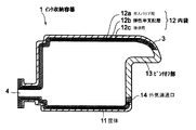
図1は、本発明の第1の実施形態によるインク収納容器の概略斜視図である。また、図2は、図1に示すインク収納容器の断面図である。
【0025】
本実施形態のインク収納容器1は、外部へインクを供給するためのインク供給口4が一端から突出しているとともに、他端から把手3が突出した、略多角柱形状(各稜線及び頂点部分は微小曲面形状をなしている)の中空容器であり、ホルダ(不図示)に着脱自在に装着されて使用される。インク供給口4には、後述する内袋12を密閉容器とするための栓部材(不図示)が設けられており、インク収納容器1がホルダに装着されることによって、栓部材を介してホルダの連結部と内袋12内の空間とが結合され、この連結部を介して、インク収納容器1内のインクが消費される。把手3は、ホルダに装着されたインク収納容器1をホルダから取り外す際に使用者が手を掛ける部分である。
【0026】
図2に示すように、インク収納容器1は、多層ブロー成形によって形成されたものであり、その断面構造として、筐体11を形成する外壁と、外壁の内層を構成し筐体11の内面と同等もしくは相似形の外面を有する内袋12を形成する内壁とを有する。
【0027】
内袋(内壁)12は可撓性を有し、かつ、筐体(外壁)11と剥離可能である。したがって、内袋12の内側であるインク収納部に収納されたインクの導出に伴い、筐体11が変形することなく内袋12のみが変形することが可能である。内袋12の厚さは、略多角柱状の各面の中央域よりも角部(曲面形状をなす場合も含む)を構成する部分の方が薄くなるように、各面の中央域から周辺に向かって徐々に減少しており、インク収納部側に凸の形状を有している。この凸の方向は、言い換えると、面の変形方向と同じであり、インク収納部の変形を促進する効果を有し、このような構成により特開平9-267483号公報に記載されているように、液体の導出に伴い、インク供給口4において特にインクジェット分野に最適な負圧を発生することが可能である。なお、図2は、主としてインク収納容器1の層構造を示すものであり、実際の各層の厚さを示すものではない。
【0028】
また、インク収納容器1の後述するピンチオフ部13の端部において、インク収納容器1には、筐体11と内袋12との隙間で構成される外気連通口14が形成されている。これにより、外気連通口14から筐体11と内袋12との間に外気を導入することができ、インク収納部内のインクの消費に伴って内袋12を容易に変形させることができる。
【0029】
さらに、内袋12は、その内側から順に、耐インク性を有する接液層12c、弾性率支配層12b、ガスバリヤ性に優れたガスバリヤ層12aが積層された3層からなり、それぞれの層が接合状態で機能分離されている。弾性率支配層12bは、インク収納容器1の使用温度範囲内でその弾性率がほぼ一定に保たれるものであり、すなわち、インク収納容器1の使用温度範囲内で内袋12の弾性率がその弾性率支配層12bによってほぼ一定に保たれる。内袋12では、接液層12cが最内層となっておれば、弾性率支配層12bおよびガスバリヤ層12aの位置は入れ替わっても構わず、弾性率支配層12bが最も外側の層で、ガスバリヤ層12aが中間の層であってもよい。
【0030】
このように内袋12が構成されていることにより、接液層12c、弾性率支配層12bおよびガスバリヤ層12aという少ない層で、内袋12がそれぞれの層の機能を十分に発揮することが可能となり、内袋12の弾性率などの、温度変化に対する影響が少なくなる。
【0031】
本実施形態においては、内袋12を構成する最も内側の接液層12cの材質として、ポリプロピレン、中間の弾性率支配層12bの材質として環状オレフィンコポリマ、最も外側のガスバリヤ層12aの材質として、EVOH(EVA(エチレン酢酸ビニル共重合体樹脂)のけん化物)が用いられている。また、筐体11の材質としては、内袋12の最内層と同じポリプロピレンが用いられている。
【0032】
ここで、内袋12を構成する3層の各層間の接着強度は、筐体11と内袋12との接着強度(剥離強度)に比べ、十分に大きく構成されている。そのため、インク収納容器1の使用時に筐体11と内袋12との層間剥離を容易に行えるとともに、内袋12を構成する各層間が剥離しないようになっている。
【0033】
前述したように、インク収納容器1は多層ブロー成形によって形成されたものであるので、インク供給口4の側、およびその反対側の端部である、把手3が設けられた側の端部に、ピンチオフ部13を有する。ピンチオフ部13は、図2に示す状態において、インク収納容器1の後端の把手3となっている部分から底部に向かって形成されている。なお、インク供給口4側のピンチオフ部13は、図2では示していない。
【0034】
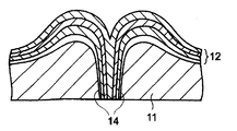
ピンチオフ部13の断面構造について、図3を参照して説明する。図3は、図2に示すインク収納容器の、ピンチオフ部を横断する方向で切断したピンチオフ部近傍の断面図である。
【0035】
図3に示すように、ピンチオフ部13は、その先端部が、インク収納容器1の外面構造において、周囲の部分に対して突出した構造とはなっておらず、インク収納容器1の外面から見て、ピンチオフ部13の周囲と実質的に同一の面を構成している。平坦なピンチオフ部13とすることで、インク収納容器1の取り扱い面からも安定し、また、安全面からも手が切れるといった問題も防止できる。さらに、インク収納容器1の外観も損なわない形状となっている。
【0036】
このような構造は、例えばインク収納容器1を成形する金型として、ピンチオフ部13において、食い切られる樹脂の樹脂溜めとなる凹部が設けられていない金型、または、樹脂溜めとなる凹部に特殊な構造を有する金型を用いて形成することができる。インク収納容器1の形成母体となるパリソンを金型で挟み込むと、ピンチオフ部13では、筐体11および内袋12は、樹脂溜めに逃げることができない樹脂の侵入により、それぞれ内側に押し上げられる。これにより、内袋12の接液層12c同士が互いに溶着される部分の両側には、筐体11および内袋12の肉厚が周囲の部分よりも厚くなった部分である、筐体11による凸部21および内袋12による凸部22が形成される。
【0037】
ここで、樹脂溜めとなる凹部に特殊な構造を有する金型を用いた凸部21及び凸部22の形成について,図8を用いて補足する。図8は、図1に示すインクタンクの製造方法を説明するための要部断面図であり、(a)は金型の型締めが進行中の状態、(b)は型締めが終了した状態を示している。
【0038】
金型30は、製造すべきインク収納容器1(図1参照)の外面と略同形状のキャビティを有しており、図8(a)に示すように、左右一対の金型30のキャビティ外面には、後述する共押し出しされたパリソンを加圧するためのパリソン狭圧領域としてのダム30bが形成されている。インク収納容器の成形母体となる、筐体11を形成する外壁用の樹脂層(第1パリソン)が外側に、内袋12を形成する内壁用のガスバリア層12a、弾性率支配層12b、接液層12cからなる樹脂層(第2パリソン)がその内側に同心円状に配置された、金型30より小径の円筒形のパリソン40を金型30で挟み込む際に、まず、突起30aと対向する金型の端部30dによりパリソン40が挟み込まれる。ここで、パリソン40のうち、型外の開放された空間である樹脂溜め30eに逃げ込めない領域の樹脂40a(金型外部の樹脂の一部)はダム30bへ押し込まれる。このとき、突起30aと端部30dとの隙間が少なくなるにつれて,ダム30b内の樹脂40aは図中矢印方向、すなわち、金型内(形成される容器の筐体外部から内袋内部側)のピンチオフ部13が形成される領域へと押し込まれる。
【0039】
そして、金型30の型締めが終了しエアなどの流体でパリソン内部を膨らませた状態では、図8(b)に示すように、この樹脂溜め39eに逃げ込めない領域の樹脂40aの押し込みにより、筐体の凸部21及び内袋の凸部22が形成される。金型30の、ピンチオフ部13を形成する領域では、金型30を閉じた状態で隙間30fが形成されるように、ダム30bの端部30cが構成されており、図8(b)で示される状態では、この隙間30fには押圧されたパリソンが存在し、ピンチオフ部13とダム30b内の樹脂40aとは連続している。この部分は、型から取り出した後、筐体外壁面を基準にバリ取りを行うことで、後述するようにピンチオフ部13を周囲と実質的に同一面に形成することが出来るとともに、ピンチオフ部13の内壁が一体となった部分が外部に露出するように形成することが出来る。このことは、後述する空隙部を形成する上でより望ましい。
【0040】
本実施形態では、上述のように型締め完了時に対向する金型30のパーティングライン同士が、パリソン40が挟まれるピンチオフ部13のパーティングラインを除き互いに当接する構造となっており、パリソン40が挟まれるピンチオフ部13のパーティングラインは若干の隙間30fを有する、すなわち、ピンチオフ部13を形成する金型30の両端部30c同士は接触せず、スリット状の微小な隙間30fを有することが望ましい。これは、この隙間30fを有することで、型締めが終了するまで前述の樹脂40aの金型内への押し込みがより確実に行なわれるためである。この結果、型締め終了時のダム30bの容積より多くの樹脂を型締め終了時にダム内で保持することはなくなるため,生産性が向上する。
【0041】
また、筐体の凸部21及び内袋の凸部22の厚みは、パリソン狭圧領域にある樹脂40aの量、及び可塑化状態の樹脂の粘弾性特性により決定される。本実施形態において粘弾性特性が同じ樹脂を使用する場合、厚みを増したい場合には、突起30aの突出量を多くし、ダム30b内に押し込まれる樹脂の量を多くするか,ダム30bの容積を減らして、多くの樹脂が金型内に流れ込むようにすればよい。
【0042】
なお、突起30aについては、開放された樹脂溜め30eに逃げることの出来ない樹脂40aをダム30bに押し込めることが出来るものであればこの形状に限られるものではない。具体的には、図8(a)に示す断面図で,型締め前の突起30aと端部30dとの距離がピンチオフ部13を形成する金型30の両端部30c同士の距離よりも短くなっていればよい。
【0043】
また、挟圧領域としてのダム30bは、型外にあるパリソン40を形成する樹脂を型内のピンチオフ部13が形成される部分に押し戻すことが出来ればよい。具体的には、突起30aなどを設ける代わりに、金型のピンチオフ部を形成する部分に本実施形態のような隙間を設け,型の厚みを厚くするとともに、その隙間が金型外方の開放された樹脂溜めに延在するようになっていてもよい。しかしながら,本実施形態のように、樹脂溜め30eに樹脂を逃がさないような突起30aを設けるほうが、より確実に樹脂を金型内へと押し込むことが出来るので望ましい。
【0044】
さて、前述したように、筐体11と内袋12とは剥離可能である。つまり、筐体11と内袋12とは互いに溶着されてはおらず、ピンチオフ部13において、内袋12は筐体11の凸部21間に挟まれて筐体11に保持されている。このように、内袋12が、筐体11の凸部21間に挟まれることにより、筐体11による内袋12の保持領域が大きくなるので、筐体11と内袋12とが溶着されていないとしても、ピンチオフ部13において内袋12が筐体11から外れることを抑制できる。また、仮に剥離した際に一時的に外れてしまっても、内袋12が筐体11から離脱しにくい構成となっているため,結果として内袋の不規則な変形を抑制することが出来る。
【0045】
ところで、外気連通口14(図2参照)は、図4に示すように、筐体11と内袋12とが剥離されることによって形成されている。しかし、この外気連通口14を構成する、筐体11と内袋12とが剥離している領域の、ピンチオフ部13全体に占める割合は小さいので、筐体11による内袋12の保持力に外気連通口14が与える影響は少ない。
【0046】
一方、内袋12に凸部22が形成されることにより、接液層12c、弾性率支配層12b、およびガスバリヤ層12aの肉厚が厚くなり、ピンチオフ部13の根元部分での内袋12の強度を向上させることができる。また、内袋12に凸部22が形成されることも、内袋12を形成する内壁同士の溶着面積を大きくし、ピンチオフ部13での内袋12を形成する内壁同士の溶着強度を向上させるのに効果がある。なお、この効果を得るためには、本発明者等の実験によれば、内袋12については、肉厚領域としての凸部22の厚みが、内袋12の他の領域の厚みの平均よりも1.5倍から4倍の範囲内にあることが望ましい。
【0047】
また、凸部21,22が形成された部分には、筐体11と内袋12との間に空隙部20aが形成されている。ここで、この空隙部20aは、内袋12による凸部22の外面と、それに対応する筐体11の内面との間に形成されるものであればよく、必ずしも凸部21は必要ではない。
【0048】
この空隙部20aを形成するための方法としては、(1)ピンチオフ部を容器外面より内方に向かって垂直に押圧または加圧する、(2)筐体の任意の個所に設けた外気連通口より筐体と内袋との間に外気を導入することで筐体と内袋との境界面と一旦剥離させ、ピンチオフ部に外気を侵入させる、(3)容器本体を押圧あるいは加圧変形させてピンチオフ部に外気を侵入させる、などの方法がある。
【0049】
以下に、この空隙部20aの機能について、図5を参照して説明する。図5は、図1に示すインク収納容器に外部から衝撃が加わったときのピンチオフ部の挙動を説明するための、ピンチオフ部の断面図である。
【0050】
例えば落下などによりインク収納容器1に外部から衝撃力が加わると、その衝撃力は、筐体11から内袋12へ伝わる。ここで、ピンチオフ部13では、その根元部の両側において筐体11と内袋12との間に空隙部20aが形成されているので、この空隙部20aが衝撃を吸収するダンパの役目を果たし、内袋12へ伝わる衝撃力を減少させることができる。
【0051】
さらに、空隙部20aはピンチオフ部13の両側に存在しているので、衝撃力が内袋12に伝わることにより、図5(a)、(b)に示すように、衝撃力の加わった向きに応じて、内袋12は左または右、あるいは左右両方向に振れて、衝撃を吸収することができる。これにより、ピンチオフ部13において内袋12の溶着部に加わるダメージが抑えられ、ピンチオフ部13の裂けといった損傷が防止されるので、ピンチオフ部13からのインクの漏れを防止することができる。
【0052】
また、筐体11と内袋12とは分離可能であるので、筐体11の凸部21に挟まれた内袋12の部分では、衝撃力が加わった時に一瞬だけ、筐体11と内袋12との間に空隙部20bが形成される。この空隙部20bが形成されている間、筐体11に加わった衝撃力は空隙部20bで略遮断される。したがって、ピンチオフ部13において外部から内袋12へ伝えられる衝撃力はより小さくなり、外部からの衝撃力によるピンチオフ部13の損傷をより効果的に防止することができる。
【0053】
なお、空隙部20bの形成は一瞬であるため、空隙部20bが形成されることによって内袋12が筐体11から外れることはない。また、図5(a)、(b)に示すように内袋12が振れた後は、内袋12は図3に示す状態に戻り、筐体11に保持される。
【0054】
以上説明したように、空隙部20aおよび空隙部20bのぞれぞれの作用により、外部からの衝撃力が加わった際の、ピンチオフ部13での内袋12の損傷を防止することができるが、もちろん、ピンチオフ部13が形成された部位においてインク収納容器1の外形形状が平坦であることも、衝撃力がピンチオフ部13に直接加わり難くし、ピンチオフ部13の損傷防止に大きく貢献している。また、インク収納容器1の外形形状や重量分布等により、より高い確率で、より高い衝撃を受ける方向に、効果的となるように、これら2種類の空隙部20a、20bを予め配分することも可能であり、こうすることにより、ピンチオフ部13の損傷を防止することができる。
【0055】
(第2の実施形態)
図6は、本発明の第2の実施形態による液体収納容器の概略斜視図である。また、図7は、図6に示す液体収容容器のピンチオフ部を横断する方向で切断したピンチオフ部についての要部断面図である。
【0056】
本実施形態の液体収納容器50は、前述の第1の実施形態と同様、筐体と筐体に対して分離可能な内袋とを有しているが、内袋には例えばシャンプーやリンスなどの液体を収容するものであり、注出口52を端部に有するポンプ部材51が、口部53に設けられている。このポンプ部材51に接続され,内部の液体を取り出すための筒部55が液体収納容器50の内部に延在しており、その開口端部55aは、液体収納容器50の底面56の近傍に位置している。この底面56には、前述の第1の実施形態と同様、ピンチオフ部58が設けられ,その近傍の内壁の肉厚領域(図7に示す内袋59の凸部60)の外面と、筐体の内面との間に空隙部57が形成されている。なお、本実施形態では、外気連通口54は液体収納容器50の口部53に任意の加工手段で穿孔されている。
【0057】
このピンチオフ部58の近傍の構造について,更に図7を用いて詳細に説明する。
【0058】
本実施形態でも,前述の第1の実施形態と同様、空隙部57は、筐体62の凸部61と、内袋59の凸部60との間に形成されている。本実施形態では、前述の第1の実施形態とは異なり、内袋59の構成が、接着性樹脂を添加したポリプロピレンなどの内層59aと、EVOHなどのバリア層59bとの積層になっている。もちろん、内容物の種類によっては、これに変えて内袋を単層にしてもよい。
【0059】
また、本実施形態の筐体62はポリプロピレンで形成されているが,その底面56については、液体収納容器50の外周部が載置面56bを形成しているのに対して、その内側の領域56aは相対的に内袋59側に突出している。そして、載置面56bとその内側の領域56aとで形成される凹部内に、ピンチオフ部58が、外部に対して突出するように設けられ,それに対応する筐体62の外壁外面が突起56cを形成している。このような容器であっても、上述の空隙部57を設けることで,外部から衝撃が加わった際にピンチオフ部58を保護することが出来る。
【0060】
このような液体収納容器は、シャンプーやリンスなどのほか、マヨネーズやケチャップなどの粘性食品、シェービングクリームなどの発泡状の粘性化粧品、液体洗剤、ゼリー状の洗顔化粧品等を収容する容器としても好適に利用できる。また、それらの内容物に応じて、本実施形態に示されるようなポンプを用いてもよいし、単なる開口としてもよい。
【0061】
【発明の効果】
以上説明したように本発明によれば、多層積層構造で、かつ層間剥離状態に構成された、ブロー成形によって形成される液体収納容器のピンチオフ部における内壁の肉厚領域で内壁と外壁との間に空隙部を形成することで、この空隙部がダンパとして機能し、液体収納容器に外部から衝撃力が加わった際のピンチオフ部の損傷、ひいてはピンチオフ部からの液体の漏れを防止することができる。また、これにより、ピンチオフ部を、筐体の外面から見てピンチオフ部の周囲と実質的に同一面に構成することもでき、ピンチオフ部が突出することによる種々の不具合も防止することができる。さらに、筐体の肉厚をピンチオフ部で厚くすることで、ピンチオフ部での筐体や内袋の強度を向上させることができるとともに、内袋同士の溶着面積も大きくなるため、ピンチオフ部での溶着強度を向上させることができる。また、このようにピンチオフ部における種々の不具合が解消された液体収納容器は、本発明の液体収納容器の製造方法および金型を用いることにより製造することができる。
【図面の簡単な説明】
【図1】本発明の第1の実施形態によるインク収納容器の概略斜視図である。
【図2】図1に示すインク収納容器の、ピンチオフ部の形成方向に沿った断面図である。
【図3】図1に示すインク収納容器の、ピンチオフ部を横断する方向で切断したピンチオフ部近傍の断面図である。
【図4】図1に示すインク収納容器の、ピンチオフ部を横断する方向で切断した外気連通口での断面図である。
【図5】図1に示すインク収納容器に外部から衝撃が加わったときのピンチオフ部の挙動を説明するための、ピンチオフ部の断面図である。
【図6】本発明の第2の実施形態による液体収納容器の概略斜視図である。
【図7】図6に示す液体収容容器のピンチオフ部を横断する方向で切断したピンチオフ部についての要部断面図である。
【図8】図1に示すインクタンクの製造方法を説明するための要部断面図であり、(a)は金型の型締めが進行中の状態、(b)は型締めが終了した状態を示す。
【図9】ブロー成形によって形成された従来の液体収納容器の一例の、ピンチオフ部近傍での断面図である。
【図10】ブロー成形によって形成された従来の液体収納容器の他の例の、ピンチオフ部近傍での断面図である。
【符号の説明】
1 インク収納容器
3 把手
4 インク供給口
11,62 筐体
12,59 内袋
13,58 ピンチオフ部
14,54 外気連通口
20a,20b,57 空隙部
21,22,60,61 凸部
30 金型
30a 突起
30b ダム
30f 隙間
40 パリソン
50 液体収納容器
51 ポンプ部材
52 注出口
53 口部
55 筒部
56 底面
56b 載置面
56c 突起[0001]
BACKGROUND OF THE INVENTION
The present invention relates to a container for storing a liquid, a method for manufacturing the container, and a mold used for the manufacturing method, and more particularly to a liquid supply destination formed by multilayer blow molding and supplying liquid to the outside. The present invention relates to a liquid storage container having a liquid supply part connected to a given supply part, a method for manufacturing the container, and a mold used in the manufacturing method.
[0002]
[Prior art]
In recent years, as a liquid storage container, a container formed by multilayer blow molding has been widely used. Blow molding involves extruding a thermoplastic resin as a tube-shaped parison, sandwiching the parison with a mold from the side, blowing air into the bag-shaped parison, inflating the parison, and contacting the inner wall of the mold. How to get a product.
[0003]
When a container is formed by blow molding, a welded portion between thermoplastic resins called a pinch-off portion is formed at an end portion in the axial direction of the parison. If the seal strength of the welded part is weak, cracks will occur in the welded part due to external impacts, etc., especially when storing ink or chemicals, from the viewpoint of safety, the impact strength of the welded part, It is important to have excellent sealing performance.
[0004]
Conventionally, in order to improve the welding strength of a pinch-off portion of a liquid container (hereinafter referred to as a blow container) formed by blow molding, as shown in FIG. A
[0005]
By the way, as shown in FIG. 9, in the case of the
[0006]
In order to solve this, a
[0007]
That is, the
[0008]
As described above, in a multi-layered liquid storage container formed by blow molding, the pinch-off portion protrudes outward to improve the impact strength and sealing performance of the container.
[0009]
On the other hand, among liquid storage containers formed by multilayer blow molding, it is a multilayer laminated structure consisting of an outer layer having shape retention and an inner layer having pressure deformability, and even in a container that can be peeled between these layers, In order to increase the welding area between the inner layers, it has been proposed to project the pinch-off portion outward (see Japanese Patent Laid-Open No. 5-310265).
[0010]
[Problems to be solved by the invention]
However, the above-described conventional structure has a structure in which the pinch-off portion protrudes in any case, so that it may interfere with other objects when the container is used, and may satisfy a necessary function in some cases. Sometimes it was impossible. Further, if the pinch-off portion is formed at a position directly held by the user's hand, there is a possibility that the handling becomes unstable or the hand is damaged. Furthermore, such a protruding pinch-off part is not preferable in appearance.
[0011]
For containers that can be peeled between layers, even if the pinch-off part protrudes outward to increase the welding area between the inner layers, the outer layer and inner layer can be peeled, so the impact strength of the container itself Also, the sealability could not be satisfied.
[0012]
An object of the present invention is to provide a liquid container having improved impact strength and sealability without causing a pinch-off portion formed by blow molding to substantially protrude outward.
[0013]
Another object of the present invention is to provide related inventions such as a manufacturing method of the liquid container and a mold used in the manufacturing method.
[0014]
[Means for Solving the Problems]
In order to achieve the above object, the liquid storage container of the present invention comprises an outer wall constituting a housing,
It has an outer surface with the same shape as the inner surface of the outer wall The Store liquid inside Flexible inner wall When,
The weld end of the inner wall is exposed to the outside of the outer wall and pinched off In a liquid storage container comprising a pinch-off unit,
The inner wall is The wall thickness region has a wall thickness region in which the wall thickness is relatively increased across the welding end, and is formed so as to be peelable from the inner surface of the outer wall except for the welding end. The outer surface of the area in front Record Wall thickness Corresponding to the region Said Between the inner surface of the outer wall In the sky A gap is formed.
[0018]
In addition, the method for manufacturing a liquid storage container according to the present invention includes an outer wall constituting the housing and an outer surface having a shape equivalent to the inner surface of the outer wall. The Store liquid inside Flexible inner wall And the inner wall The welding end for closing the pin is exposed to the outside of the outer wall and pinched off In a manufacturing method of a liquid storage container comprising a pinch-off unit,
Providing a mold having a cavity having the same shape as the outer surface of the liquid storage container, a first parison for a cylindrical outer wall having a smaller diameter than the mold, and a second parison for an inner wall;
A step of sandwiching the first and second parisons with the mold and pushing a resin forming the first and second parisons outside the mold into a portion of the mold where the pinch-off portion is formed; ,
Air is introduced into the interior, the first and second parisons are inflated to conform to the mold, and the outer wall and the inner wall are connected to each other. Peeling A process that can be formed;
The wall thickness of the inner wall having a wall thickness region formed so as to be peelable from the inner surface of the outer wall excluding the weld end and having a relatively thick wall across the weld end. Between the outer surface of the region and the inner surface of the outer wall corresponding to the wall thickness region Forming a void portion.
[0020]
In the present specification, the “root portion” and the “tip portion” of the pinch-off portion mean the root portion and the tip portion in the pinch-off portion in the direction from the inner surface to the outer surface of the liquid storage container.
[0021]
In addition, “multilayer blow molding” in the present invention means so-called coextrusion multilayer blow molding in which a co-extruded multilayer parison is sandwiched between divided molds and a pressurized fluid is introduced into the parison and expanded. To do.
[0022]
Further, the “liquid” in the present invention is used to include a sol-like viscous fluid.
[0023]
DETAILED DESCRIPTION OF THE INVENTION
Next, embodiments of the present invention will be described with reference to the drawings.
[0024]
(First embodiment)
FIG. 1 is a schematic perspective view of an ink storage container according to the first embodiment of the present invention. FIG. 2 is a cross-sectional view of the ink storage container shown in FIG.
[0025]
The ink storage container 1 of the present embodiment has a substantially polygonal column shape (each ridge line and apex portion is formed by an ink supply port 4 for supplying ink to the outside protruding from one end and a handle 3 protruding from the other end. A hollow container (having a minute curved surface shape), which is used by being detachably attached to a holder (not shown). The ink supply port 4 is provided with a plug member (not shown) for making an inner bag 12 (to be described later) into a sealed container. When the ink storage container 1 is attached to the holder, the holder is inserted through the plug member. And the space in the
[0026]
As shown in FIG. 2, the ink container 1 is formed by multilayer blow molding, and has a cross-sectional structure of an outer wall that forms the
[0027]
The inner bag (inner wall) 12 has flexibility and can be peeled off from the housing (outer wall) 11. Therefore, only the
[0028]
In addition, at the end of a pinch-
[0029]
Further, the
[0030]
By configuring the
[0031]
In the present embodiment, polypropylene is used as the material of the innermost
[0032]
Here, the adhesive strength between the three layers constituting the
[0033]
As described above, since the ink storage container 1 is formed by multilayer blow molding, the ink supply port 4 side and the opposite end, that is, the end on the side where the handle 3 is provided are provided. And a pinch-
[0034]
A cross-sectional structure of the pinch-
[0035]
As shown in FIG. 3, the pinch-
[0036]
Such a structure, for example, as a mold for molding the ink storage container 1, is specially provided in a mold that does not have a recess that serves as a resin reservoir for the resin that can be cut off in the pinch-
[0037]
Here, the formation of the
[0038]
The
[0039]
When the
[0040]
In the present embodiment, as described above, the parting lines of the
[0041]
Moreover, the thickness of the
[0042]
The
[0043]
Moreover, the dam 30b as a pinching area | region should just push back the resin which forms the parison 40 outside a type | mold to the part in which the pinch-
[0044]
As described above, the
[0045]
Incidentally, the outside air communication port 14 (see FIG. 2) is formed by peeling the
[0046]
On the other hand, by forming the
[0047]
Further, a
[0048]
As a method for forming the
[0049]
Hereinafter, the function of the
[0050]
For example, when an impact force is applied to the ink storage container 1 from the outside by dropping or the like, the impact force is transmitted from the
[0051]
Further, since the
[0052]
Moreover, since the housing | casing 11 and the
[0053]
In addition, since formation of the space |
[0054]
As described above, the
[0055]
(Second Embodiment)
FIG. 6 is a schematic perspective view of a liquid storage container according to the second embodiment of the present invention. FIG. 7 is a cross-sectional view of the main part of the pinch-off part cut in a direction crossing the pinch-off part of the liquid container shown in FIG.
[0056]
The liquid storage container 50 of the present embodiment has a housing and an inner bag separable from the housing, as in the first embodiment described above. The inner bag may be a shampoo or a rinse, for example. A pump member 51 having a spout 52 at the end is provided in the mouth 53. A cylindrical portion 55 connected to the pump member 51 and used to take out the liquid inside extends to the inside of the liquid storage container 50, and its open end 55 a is positioned near the bottom surface 56 of the liquid storage container 50. is doing. Similar to the first embodiment, the bottom surface 56 is provided with a pinch-off portion 58. The outer surface of the thick wall region of the inner wall (the
[0057]
The structure in the vicinity of the pinch-off portion 58 will be further described in detail with reference to FIG.
[0058]
Also in this embodiment, the
[0059]
The casing 62 of the present embodiment is made of polypropylene. Regarding the bottom surface 56, the outer peripheral portion of the liquid storage container 50 forms the mounting surface 56b, whereas the inner region of the casing 62 is formed. 56a protrudes relatively toward the inner bag 59 side. A pinch-off portion 58 is provided in the recess formed by the placement surface 56b and the
[0060]
Such a liquid storage container is suitable as a container for storing viscous foods such as mayonnaise and ketchup, foamy viscous cosmetics such as shaving cream, liquid detergents, jelly-like facial cosmetics, etc. in addition to shampoo and rinse. Available. Moreover, according to those contents, a pump as shown in this embodiment may be used, or a simple opening may be used.
[0061]
【The invention's effect】
As described above, according to the present invention, between the inner wall and the outer wall in the thick region of the inner wall in the pinch-off portion of the liquid storage container formed by blow molding, which is configured in a multilayer laminated structure and in a delaminated state. By forming a gap in the gap, the gap functions as a damper, and it is possible to prevent damage to the pinch-off part when an impact force is applied to the liquid storage container from the outside, and thus leakage of liquid from the pinch-off part. . In addition, as a result, the pinch-off portion can be configured to be substantially flush with the periphery of the pinch-off portion when viewed from the outer surface of the housing, and various problems due to the protruding pinch-off portion can be prevented. Furthermore, by increasing the thickness of the casing at the pinch-off part, the strength of the casing and inner bag at the pinch-off part can be improved, and the welding area between the inner bags also increases, so the pinch-off part The welding strength can be improved. In addition, the liquid storage container in which various problems in the pinch-off portion are eliminated as described above can be manufactured by using the liquid storage container manufacturing method and the mold according to the present invention.
[Brief description of the drawings]
FIG. 1 is a schematic perspective view of an ink storage container according to a first embodiment of the present invention.
FIG. 2 is a cross-sectional view of the ink container shown in FIG. 1 along the formation direction of a pinch-off portion.
3 is a cross-sectional view of the vicinity of the pinch-off portion of the ink container shown in FIG. 1 cut in a direction crossing the pinch-off portion.
4 is a cross-sectional view of the ink storage container shown in FIG. 1 at an outside air communication port cut in a direction crossing a pinch-off portion.
FIG. 5 is a cross-sectional view of the pinch-off portion for explaining the behavior of the pinch-off portion when an impact is applied to the ink storage container shown in FIG. 1 from the outside.
FIG. 6 is a schematic perspective view of a liquid storage container according to a second embodiment of the present invention.
7 is a cross-sectional view of the main part of the pinch-off part cut in a direction crossing the pinch-off part of the liquid container shown in FIG. 6. FIG.
FIGS. 8A and 8B are cross-sectional views for explaining a manufacturing method of the ink tank shown in FIG. 1, wherein FIG. 8A is a state in which mold clamping is in progress, and FIG. 8B is a state in which mold clamping is completed. Indicates.
FIG. 9 is a cross-sectional view in the vicinity of a pinch-off portion of an example of a conventional liquid storage container formed by blow molding.
FIG. 10 is a cross-sectional view in the vicinity of a pinch-off portion of another example of a conventional liquid storage container formed by blow molding.
[Explanation of symbols]
1 Ink storage container
3 Handle
4 Ink supply port
11,62 housing
12,59 inner bag
13, 58 Pinch-off part
14,54 Open air communication port
20a, 20b, 57 gap
21, 22, 60, 61 Convex
30 mold
30a protrusion
30b Dam
30f clearance
40 Parison
50 Liquid container
51 Pump member
52 Outlet
53 mouth
55 Tube
56 Bottom
56b Placement surface
56c protrusion
Claims (9)
前記外壁の内面と同等の形状の外面を有して内部に液体を収納する可撓性の内壁と、
前記内壁を閉じるための溶着端部が前記外壁の外側へ露出してピンチオフされたピンチオフ部と、を備える液体収納容器において、
前記内壁は、前記溶着端部を挟んで壁の厚みが相対的に厚くなった壁厚領域を有し、前記溶着端部を除いて前記外壁の内面に対して剥離可能に形成されて、前記壁厚領域の外面と前記壁厚領域に対応する前記外壁の内面との間に空隙部を形成することを特徴とする液体収納容器。An outer wall constituting the housing;
A flexible inner wall for accommodating the liquid therein having an inner surface and an outer surface of the same shape of the outer wall,
In a liquid storage container comprising: a welding end for closing the inner wall exposed to the outside of the outer wall and pinched off .
The inner wall has a wall thickness region in which the thickness of the wall is relatively increased across the welding end, and is formed so as to be peelable from the inner surface of the outer wall except for the welding end. liquid container and forming an air gap portion between the inner surface of the outer wall corresponding to the outer surface prior Symbol wall thickness region of the wall thickness region.
前記外壁の内面と同等の形状の外面を有して内部に液体を収納する可撓性の内壁と、
前記内壁を閉じるための溶着端部が前記外壁の外側へ露出してピンチオフされたピンチオフ部と、を備える液体収納容器の製造方法において、
該液体収納容器の外面と同形状のキャビティを有する型と、該型より小さい径の円筒形の外壁用の第1パリソン及び内壁用の第2パリソンを用意する工程と、
該第1、第2パリソンを前記型で挟み込むとともに、前記型の外にある前記第1、第2パリソンを形成する樹脂を前記型の内にある前記ピンチオフ部が形成される部分に押し込む工程と、
内部にエアを導入して前記第1、第2パリソンを膨張させて前記型に沿わせ、前記外壁と内壁を剥離可能に形成する工程と、
前記溶着端部を除いて前記外壁の内面に対して剥離可能に形成されて、前記溶着端部を挟んで壁の厚みが相対的に厚くなった壁厚領域を有する前記内壁の、前記壁厚領域の外面と前記壁厚領域に対応する前記外壁の内面との間に空隙部を形成する工程と、を有することを特徴とする液体収納容器の製造方法。An outer wall constituting the housing;
A flexible inner wall for accommodating the liquid therein having an inner surface and an outer surface of the same shape of the outer wall,
In a manufacturing method of a liquid storage container, comprising a pinch-off portion that is pinched off by exposing a welding end portion for closing the inner wall to the outside of the outer wall ,
Providing a mold having a cavity having the same shape as the outer surface of the liquid storage container, a first parison for a cylindrical outer wall having a smaller diameter than the mold, and a second parison for an inner wall;
A step of sandwiching the first and second parisons with the mold and pushing a resin forming the first and second parisons outside the mold into a portion of the mold where the pinch-off portion is formed; ,
Introducing air into the interior, inflating the first and second parisons, along the mold, and forming the outer wall and the inner wall so as to be peelable ;
The wall thickness of the inner wall having a wall thickness region formed so as to be peelable from the inner surface of the outer wall excluding the weld end and having a relatively thick wall across the weld end. Forming a gap between the outer surface of the region and the inner surface of the outer wall corresponding to the wall thickness region .
前記第1、第2パリソンを形成する樹脂を前記型内の前記ピンチオフ部が形成される部分に押し込む工程は、前記パリソン挟圧部に樹脂を保持するとともに該保持された樹脂を前記型内に押し込むことによって行なわれることを特徴とする請求項8に記載の液体収納容器の製造方法。The mold is a pair of left and right, and a pinch-off portion forming surface in each mold is used to push the resin forming the first and second parisons outside the mold into the mold when clamping. While having a parison clamping part that holds a part of the resin,
The step of pushing the resin forming the first and second parisons into the portion of the mold where the pinch-off portion is formed includes holding the resin in the parison clamping portion and placing the held resin in the mold. The method for producing a liquid container according to claim 8 , wherein the method is performed by pushing.
Priority Applications (1)
| Application Number | Priority Date | Filing Date | Title |
|---|---|---|---|
| JP2001286483A JP4834260B2 (en) | 2000-10-05 | 2001-09-20 | Liquid storage container and method for manufacturing the container |
Applications Claiming Priority (4)
| Application Number | Priority Date | Filing Date | Title |
|---|---|---|---|
| JP2000-306263 | 2000-10-05 | ||
| JP2000306263 | 2000-10-05 | ||
| JP2000306263 | 2000-10-05 | ||
| JP2001286483A JP4834260B2 (en) | 2000-10-05 | 2001-09-20 | Liquid storage container and method for manufacturing the container |
Publications (3)
| Publication Number | Publication Date |
|---|---|
| JP2002187294A JP2002187294A (en) | 2002-07-02 |
| JP2002187294A5 JP2002187294A5 (en) | 2008-10-16 |
| JP4834260B2 true JP4834260B2 (en) | 2011-12-14 |
Family
ID=26601614
Family Applications (1)
| Application Number | Title | Priority Date | Filing Date |
|---|---|---|---|
| JP2001286483A Expired - Lifetime JP4834260B2 (en) | 2000-10-05 | 2001-09-20 | Liquid storage container and method for manufacturing the container |
Country Status (1)
| Country | Link |
|---|---|
| JP (1) | JP4834260B2 (en) |
Families Citing this family (9)
| Publication number | Priority date | Publication date | Assignee | Title |
|---|---|---|---|---|
| CN1122626C (en) * | 2000-10-05 | 2003-10-01 | 佳能株式会社 | Liquid container and its producing method and melt mould for liquid container producing method |
| US20090321383A1 (en) * | 2008-06-30 | 2009-12-31 | Lane Michael T | Single serve container |
| JP6025040B2 (en) * | 2012-10-31 | 2016-11-16 | 株式会社吉野工業所 | Blow molding container and blow molding method |
| EP3075670B1 (en) | 2013-11-27 | 2019-04-24 | Kyoraku Co., Ltd. | Delamination container |
| JP6531371B2 (en) * | 2013-11-27 | 2019-06-19 | キョーラク株式会社 | Peeling container |
| JP6540017B2 (en) * | 2014-12-19 | 2019-07-10 | キョーラク株式会社 | Peeling container |
| JP2016193743A (en) * | 2015-03-31 | 2016-11-17 | 株式会社吉野工業所 | Double container |
| JP6737590B2 (en) * | 2015-12-09 | 2020-08-12 | 株式会社平和化学工業所 | Double container and manufacturing method thereof |
| JP6735112B2 (en) * | 2016-02-16 | 2020-08-05 | 株式会社平和化学工業所 | Double container and manufacturing method thereof |
Family Cites Families (4)
| Publication number | Priority date | Publication date | Assignee | Title |
|---|---|---|---|---|
| JPS5472271A (en) * | 1977-11-19 | 1979-06-09 | Showa Yuka Kk | Method of making laminated container |
| JPS5515861A (en) * | 1978-07-24 | 1980-02-04 | Kyoraku Co Ltd | Multi-layer hollow body and manufacturing method |
| JP3406997B2 (en) * | 1994-08-09 | 2003-05-19 | 株式会社吉野工業所 | Synthetic resin bottle and molding method |
| JP3251845B2 (en) * | 1995-04-17 | 2002-01-28 | キヤノン株式会社 | Liquid container for applying negative pressure, method for manufacturing the container, ink jet cartridge integrating the container with an ink jet recording head, and ink jet recording apparatus |
-
2001
- 2001-09-20 JP JP2001286483A patent/JP4834260B2/en not_active Expired - Lifetime
Also Published As
| Publication number | Publication date |
|---|---|
| JP2002187294A (en) | 2002-07-02 |
Similar Documents
| Publication | Publication Date | Title |
|---|---|---|
| JP5418649B2 (en) | Multi-chamber container | |
| JP4834260B2 (en) | Liquid storage container and method for manufacturing the container | |
| JP2001516314A (en) | Multiple neck spray bottle, multiple neck spray bottle dispenser, and methods of making and using same | |
| JP6547242B2 (en) | container | |
| EP1199252B1 (en) | Liquid container and method of its manufacturing | |
| JP2004059141A (en) | Plastic made refill container | |
| JP5702056B2 (en) | Refill container | |
| JP2006306435A (en) | Container | |
| JP6366518B2 (en) | Squeeze foamer container | |
| JP4209288B2 (en) | Blow-molded standing thin container suitable for pouch replacement | |
| JPH111249A (en) | Packaging bag | |
| JP4678664B2 (en) | Small capacity container with twist-off port | |
| JP7139064B2 (en) | double container | |
| JP4336179B2 (en) | Self-supporting bag | |
| JP2004175406A (en) | Container and method of reducing its volume | |
| JP4267413B2 (en) | Method and apparatus for manufacturing contents-enclosed container | |
| JP7471750B2 (en) | Double container | |
| JP4191554B2 (en) | Squeeze type delamination container | |
| JP2002087443A (en) | Packaging bag | |
| JP2002002761A (en) | Extrusion container | |
| JP7286249B2 (en) | Synthetic resin container and method for manufacturing synthetic resin container | |
| JP7317450B2 (en) | double container | |
| JP2021127164A (en) | Double container | |
| JP2022012033A (en) | Double container | |
| JP2021187512A (en) | Double container |
Legal Events
| Date | Code | Title | Description |
|---|---|---|---|
| A521 | Written amendment |
Free format text: JAPANESE INTERMEDIATE CODE: A523 Effective date: 20080901 |
|
| A621 | Written request for application examination |
Free format text: JAPANESE INTERMEDIATE CODE: A621 Effective date: 20080901 |
|
| RD03 | Notification of appointment of power of attorney |
Free format text: JAPANESE INTERMEDIATE CODE: A7423 Effective date: 20080926 |
|
| A521 | Written amendment |
Free format text: JAPANESE INTERMEDIATE CODE: A821 Effective date: 20080926 |
|
| A977 | Report on retrieval |
Free format text: JAPANESE INTERMEDIATE CODE: A971007 Effective date: 20110411 |
|
| A131 | Notification of reasons for refusal |
Free format text: JAPANESE INTERMEDIATE CODE: A131 Effective date: 20110517 |
|
| A521 | Written amendment |
Free format text: JAPANESE INTERMEDIATE CODE: A523 Effective date: 20110719 |
|
| TRDD | Decision of grant or rejection written | ||
| A01 | Written decision to grant a patent or to grant a registration (utility model) |
Free format text: JAPANESE INTERMEDIATE CODE: A01 Effective date: 20110907 |
|
| A01 | Written decision to grant a patent or to grant a registration (utility model) |
Free format text: JAPANESE INTERMEDIATE CODE: A01 |
|
| A61 | First payment of annual fees (during grant procedure) |
Free format text: JAPANESE INTERMEDIATE CODE: A61 Effective date: 20110926 |
|
| R150 | Certificate of patent or registration of utility model |
Ref document number: 4834260 Country of ref document: JP Free format text: JAPANESE INTERMEDIATE CODE: R150 Free format text: JAPANESE INTERMEDIATE CODE: R150 |
|
| FPAY | Renewal fee payment (event date is renewal date of database) |
Free format text: PAYMENT UNTIL: 20140930 Year of fee payment: 3 |
|
| R250 | Receipt of annual fees |
Free format text: JAPANESE INTERMEDIATE CODE: R250 |
|
| R250 | Receipt of annual fees |
Free format text: JAPANESE INTERMEDIATE CODE: R250 |
|
| R250 | Receipt of annual fees |
Free format text: JAPANESE INTERMEDIATE CODE: R250 |
|
| R250 | Receipt of annual fees |
Free format text: JAPANESE INTERMEDIATE CODE: R250 |
|
| R250 | Receipt of annual fees |
Free format text: JAPANESE INTERMEDIATE CODE: R250 |
|
| R250 | Receipt of annual fees |
Free format text: JAPANESE INTERMEDIATE CODE: R250 |
|
| R250 | Receipt of annual fees |
Free format text: JAPANESE INTERMEDIATE CODE: R250 |
|
| EXPY | Cancellation because of completion of term |