JP2004175406A - Container and method of reducing its volume - Google Patents
Container and method of reducing its volume Download PDFInfo
- Publication number
- JP2004175406A JP2004175406A JP2002343746A JP2002343746A JP2004175406A JP 2004175406 A JP2004175406 A JP 2004175406A JP 2002343746 A JP2002343746 A JP 2002343746A JP 2002343746 A JP2002343746 A JP 2002343746A JP 2004175406 A JP2004175406 A JP 2004175406A
- Authority
- JP
- Japan
- Prior art keywords
- container body
- container
- fluid passage
- volume
- molding
- Prior art date
- Legal status (The legal status is an assumption and is not a legal conclusion. Google has not performed a legal analysis and makes no representation as to the accuracy of the status listed.)
- Pending
Links
Images


Abstract
Description
【0001】
【発明の属する技術分野】
本発明は、各種の液体(粘性体を含む)、粉体等を充填するのに用いられる容器および該容器を充填前に減容化する方法に関する。
【0002】
【従来の技術】
この種の容器として、スタンディングパウチ、ガゼットパウチ等のパウチが広く用いられている。これらのパウチは、プラスチックフィルムを貼り合わせて袋状に形成したものであるので、容易に折り畳むことができる。したがって、内容物を充填する前の保管時や輸送時に嵩張らない上、内容物を使用した後の廃棄時にもゴミの減容化を図ることができる。
【0003】
その反面、パウチは、フィルムの貼合せに人体にとってあまり好ましくない接着剤が使用されることがある上、製造工程においてフィルムが外気に晒されるため、特に、内容物が食品や医薬品の場合には、材料選定および工場環境の制約があり、充填前に容器内の滅菌処理が必要であった。また、パウチの場合、材料のフィルム自体が高価であって、コンバーティング費用や製袋費用もかかるため、コスト高になってしまう。
【0004】
一方、この種の容器としては、ブロー成形容器も広く用いられている。特に、飲料用ボトルは、その大半をブロー成形容器が占めている。ブロー成形容器は、通常、金型内に配置したパリソンに空気を吹き込んでこれを膨らませることにより形成されるものであるため、パウチと比べて製造コストが安くつく上、デザイン形状の制約が少ないというメリットがある。
【0005】
しかしながら、ブロー成形容器の場合、接着剤は使用されていないものの、成形後から充填時までに、容器内にその口部を通じて埃や雑菌などが入り込む恐れがあり、食品や医薬品を充填する場合には、やはり容器内の滅菌処理が必要であった。
【0006】
さらに、この種の容器として、真空成形容器も一部採用されており、これは上述したブロー成形容器とほぼ同様の特性を持つものである。
【0007】
ところで、ブロー成形容器については、成形時に容器本体の表面に所要の折り線を形成しておき、廃棄時に、折り線に沿って折り畳むことにより、減容化を可能にしたものが提案されている(例えば、特許文献1参照)。
【0008】
【特許文献1】
特開2001−247112号公報(特許請求の範囲、図2等)
【0009】
【発明が解決しようとする課題】
しかしながら、上記の折り線付きブロー成形容器の場合、保管時や輸送時は、成形時と同じく中空状のままであるため、非常に嵩張り、物流コストの増大を招くという問題があった。
【0010】
本発明は、上記の問題点に鑑みてなされたものであって、容器本体がブロー成形法等によって中空状に成形される容器を、廃棄時はもとより未充填時にも減容化できるようにすることを目的とする。
【0011】
【課題を解決するための手段および発明の効果】
本発明による容器の減容化方法は、容器本体が中空状に成形される容器を、充填時まで減容化しておく方法であって、容器本体をこれの所定部位に折り畳み案内部が形成されるような金型を用いて成形することと、成形された容器本体を折り畳み案内部に沿って偏平状に折り畳むことと、折り畳まれた容器本体の気密を保つことによってその形態を維持することとを含んでいる。
【0012】
上記方法によれば、容器本体が中空状に成形される容器を、内容物の充填前において、簡単にかつパウチの場合とほぼ同程度まで減容化することができる。したがって、従来のブロー成形容器や真空成形容器の場合と比べて物流コストを大幅に下げることができる。
【0013】
本発明による容器の減容化方法において、容器本体の折り畳みを、容器本体内の減圧脱気によって行う場合がある。この場合、例えば、容器本体の開口にバキュームノズルを挿入し、このノズルを通じて容器本体内を減圧脱気することによって、容器本体の折り畳みを確実にかつきれいに行うことができる。
【0014】
本発明による容器の減容化方法において、容器本体の折り畳みを、容器本体内の減圧脱気と、減圧脱気と同時またはその後の加熱成形とによって行う場合もある。
【0015】
この場合、前述した減圧脱気のみによる場合と比べて、偏平状に折り畳まれた容器本体の形態を、より安定化することができる。加熱成形は、例えば、60〜80℃程度の条件下で行われる。
【0016】
上記2つの場合において、容器本体の成形を、滅菌された空気を使用したブロー成形法によって行い、成形直後に容器本体内を減圧脱気することがある。
【0017】
この方法によれば、容器本体の内部が成形時から充填時まで全く外気に晒されず、埃や雑菌が侵入する恐れがない。よって、食品や医薬品を充填する場合でも、充填前の滅菌処理が不要となる。
【0018】
なお、容器本体の成形は、上述したブロー成形法の他、真空成形法や圧空成形法等によって行われても勿論よい。
【0019】
また、本発明による容器の減容化方法において、容器本体の折り畳みを、加熱成形によって行う場合もある。
【0020】
上記の場合、加熱成形によって、容器本体を確実に偏平状に折り畳むことができ、また、その形態を安定化させることができる。
【0021】
本発明による容器の減容化方法において、容器本体の気密保持を、流体通路を有しかつ容器本体の開口に固定した口部材に、流体通路を閉鎖し得る閉鎖部材を着脱自在に接続することによって行う場合がある。
【0022】
次に、本発明による容器は、中空状に成形されかつ折り畳み案内部を有する容器本体と、容器本体の開口に設けられる気密保持手段とを備え、容器本体は、折り畳み案内部に沿って偏平状に折り畳まれるとともに、その形態が気密保持手段によって充填時まで維持されるようになっている。
【0023】
本発明の容器によれば、容器本体が充填時まで偏平状に折り畳まれた形態に維持されるので、従来のブロー成形容器や真空成形容器と比べて大幅に減容化することができる。また、容器本体は充填時まで気密が保たれるので、保管時や輸送時に、内部に埃や雑菌が侵入する恐れがなく、衛生的である。折り畳まれた容器本体は、気密が解除されて、内容物が充填されることにより、成形時の中空状の形態にほぼ復元する。そして、容器本体の開口に所要の閉鎖手段が施された上で、市場に流通し、消費者の使用に供される。内容物の使用後に容器を廃棄する場合には、容器本体を折り畳み案内部に沿って折り畳むことにより、減容化することができる。このように、本発明による容器によれば、廃棄時はもとより充填前においても、パウチとほぼ同程度まで減容化することができ、それによって物流コストを抑えることができる。つまり、本発明によれば、パウチとほぼ同等の優れた減容性を兼ね備えた、中空成形容器が得られる。
【0024】
容器本体の厚みは、好ましくは50〜250μm、より好ましくは80〜180μmとなされる。容器本体の厚みが50μmを下回ると、内容物を充填した状態での自立性や形態保持性の確保が困難となる。また、容器本体の厚みが250μmを上回ると、折れ曲がるべき部位の剛性が大きくなりすぎて、折り畳みが困難となり、減容化に支障を来すおそれがある。
【0025】
容器本体は、要求されるバリヤー性や対内容物適正に応じて、適宜の熱可塑性樹脂材料から形成すればよいが、通常、ポリエチレン、ポリプロピレン、エバール(商標)等のエチレンビニルアルコール共重合体、ナイロン、およびアイオノマーよりなる群から選ばれた熱可塑性樹脂よりなる単層または多層構造のものとなされる。容器本体の成形は、通常、ブロー成形法によって行われるが、真空成形法や圧空成形法等によって行われてもよい。
【0026】
折り畳み案内部は、通常、容器本体に形成された複数のスコア線および/またはリブ線よりなる。スコアやリブは、容器本体の成形に用いられる金型の内面に予め所要の凸条、凹溝を形成しておくことにより、容器本体の成形と同時に形成することができる。また、折り畳み案内部は、容器本体の所要部分に形成された蛇腹部であってもよい。このような蛇腹部も、成形と同時に形成することができる。なお、折り畳み案内部は、上記以外のものであっても勿論よい。折り畳み案内部の形成箇所、形状および寸法は、容器本体の剛性や形状等に応じて適宜に決定される。
【0027】
本発明による容器において、気密保持手段が、流体通路を有しかつ容器本体の開口に固定される口部材と、口部材に着脱自在に接続されて流体通路を閉鎖する閉鎖部材とよりなる場合がある。
【0028】
上記の場合、口部材への閉鎖部材の着脱によって流体通路を開閉することができるので、その操作が簡単である。
【0029】
上記において、口部材は、容器本体の折り畳み手段に減圧脱気が含まれている場合には、その前に容器本体の開口に固定されるが、それ以外の場合には、容器本体の折り畳みの前後いずれでも構わない。口部材は、例えば、余熱が残った成形直後の容器本体の開口に挿入することによって、容器本体の開口に固定することができるが、より完全な気密性が要求される場合には、容器本体の開口にヒートシールによって固定するようにしてもよい。
【0030】
閉鎖部材としては、各種のプラグやキャップを挙げることができる。
【0031】
この閉鎖部材は、口部材の流体通路の外端開口を閉鎖するものであってもよいし、口部材に結合されかつ流体通路の内端開口を閉鎖するものであってもよい。
【0032】
前者の場合、容器において一般に採用されているキャップやプラグを閉鎖部材とすればよい。
【0033】
後者の場合、例えば次のような構成を採用することができる。即ち、口部材が、軸方向に貫通した流体通路を有しかつ容器本体に固定される雌部材よりなり、閉鎖部材が、雌部材の内端部に着脱自在に係合して流体通路の内端開口を閉鎖し得るものとなされる。雌部材の流体通路には、閉鎖部材に係合する頭部および頭部に連なる棒状部を有する雄部材を外方から挿抜自在に挿入し得るようになっており、雄部材の棒状部に、その基端から先端部に至る流体通路が形成されるとともに、棒状部の先端部における流体通路の周囲の部分に、流体通路を外部に通じさせる貫通孔が形成されている。そして、雄部材を雌部材の流体通路に挿入することにより、その頭部が閉鎖部材に係合して閉鎖部材が雌部材の内端部から外れ、かつ貫通孔が容器本体内に臨ませられ、一方、雄部材を雌部材の流体通路から引き抜くことにより、雄部材の頭部とともに内方に移動した閉鎖部材が雌部材の内端部に係合して流体通路の内端開口を閉鎖し、かつ雄部材の頭部が閉鎖部材から外れるようになっている。
【0034】
上記の場合、閉鎖部材による口部材(雌部材)の流体通路の開閉が、流体通路への雄部材の挿入または引抜きによって行われるため、容器本体の気密およびその解除を簡単に行い得る。また、例えば、減圧脱気用バキュームノズル、充填用ノズル、および充填後に口部材に接続するスパウトとして、前記雄部材の構成を備えたものを用いれば、容器本体の折り畳み時から充填時、さらには充填後まで口部材(雌部材)を一貫して使用することができ、それによって、各工程の省力化、製造コストの削減、衛生管理の負担軽減等を図ることができる。
【0035】
なお、容器本体の気密保持手段は、上述したものに限定されず、その他の手段を適宜用いることも勿論可能である。例えば、容器本体内からの流体の流出のみを許容する逆止弁を備えた口部材や、雄型コネクタが挿入されている時のみ流体通路を開く自閉弁を備えた口部材を、気密保持手段としてもよい。
【0036】
【発明の実施の形態】
図1および2には、本発明による容器の減容化方法の1つの実施形態が示されている。この実施形態において、容器本体は、ブロー成形法によって成形される。図1には、容器本体の成形までの工程が示されている。図1(a)は、インジェクションブロー成形の例を示すものであって、パリソン(P1)は、射出成形により成形された有底筒状のものである。図1(b)は、ダイレクトブロー成形の例を示すものであって、パリソン(P2)は、押出機から押し出された筒状のものである。図1(c)は、フィルムインフレーション法によって製造された筒状のフィルムをパリソン(P3)として使用した成形例を示すものである。図1(d)は、複合フィルムの両縁部をヒートシールして筒状にしながらこれをパリソン(P4)として金型に供給する成形例を示すものである。
【0037】
そして、図1(e)に示すように、パリソンを金型(M1)に入れる。なお、図1(e)では、図1(c)または(d)のパリソン(P3)(P4)を使用した場合が示されており、この場合、金型(M1)が閉じられると、パリソン(P3)(P4)の開口部が金型に挟まれてヒートシールされ、袋状に形成される。なお、詳しい図示は省略したが、金型(M1)の内面には、成形すべき容器本体の所定部分にスコア線、リブ線等の折り畳み案内部が形成されるように、所要の凸条、凹溝等が予め形成されている。
【0038】
こうしておいて、図1(f)に示すように、パリソン(P3)(P4)内に、その上端開口から、滅菌された空気を吹き込む。すると、パリソン(P3)(P4)が膨らんで金型(M1)の内面に密着させられる。これにより、折り畳み案内部を有する中空状の容器本体(10)が成形される。
【0039】
図2は、容器本体(10)の成形以降の工程を示すものである。図2(a)に示すように、成形直後の容器本体(10)の開口に、口部材(3)を挿入して、これをヒートシールにより固定する。口部材(3)は、上下方向に貫通した流体通路(図示略)を有している。なお、図2では図示を省略したが、口部材(3)には、その下端開部に着脱自在に係合して流体通路の下端開口を閉鎖し得る閉鎖部材が連結されている。雌部材(3)を容器本体(10)の開口へ挿入する際には、閉鎖部材によって口部材(3)の流体通路を閉鎖しておく。閉鎖部材による口部材(3)の流体通路の開閉は、流体通路への雄部材の挿入または引抜きによって行うことができるようになっている。
【0040】
次に、図2(b)に示すように、容器本体(10)を金型(M1)から取り出して、口部材(3)の流体通路に、前記雄部材の構造を備えたバキュームノズル(B)を挿入する。すると、閉鎖部材が口部材(3)の下端部から外れて流体通路が開き、この流体通路を通じて、容器本体(10)内が減圧脱気される。
【0041】
内部の減圧脱気によって、容器本体(10)は、図2(c)に示すように、折り畳み案内部に沿って偏平状に折り畳まれる。その後、口部材(3)の流体通路からバキュームノズル(B)を引き抜くと、閉鎖部材によって流体通路が閉じられ、容器本体(10)の気密が保持される。
【0042】
さらに、図2(d)に示すように、折り畳まれた容器本体(10)を、60〜80℃の加熱下で、プレス金型(M2)により加熱成形する。
【0043】
こうして、図2(e)に示すように、容器本体(10)が偏平状に折り畳まれた減容形態に維持されている容器が得られる。
【0044】
図3は、本発明による容器の減容化方法のもう1つの実施形態を示すものである。この実施形態において、容器本体の成形までの工程は、図1に示す上記の実施形態と同じであるので、説明を省略する。
【0045】
この実施形態では、ブロー成形後に金型から取り出した容器本体(10)を、図3(a)に示すように、60〜80℃の加熱下で、プレス金型(M2)により加熱成形する。すると、容器本体(10)が折り畳み案内部に沿って偏平状に折り畳まれる。また、これに伴って、容器本体内が脱気される。
【0046】
次に、図3(b)に示すように、折り畳まれた容器本体(10)の開口に、閉鎖部材付き口部材(3)を挿入して、ヒートシールにより固定する。
【0047】
こうして、図3(c)に示すように、容器本体(10)が偏平状に折り畳まれた減容形態に維持されている容器(C)が得られる。
【0048】
図4〜6は、本発明による容器の第1の実施形態を示すものである。この容器(C1)は、ブロー成形法によって中空状に成形されかつ折り畳み案内部(11A)を有する熱可塑性樹脂製容器本体(11)と、容器本体(11)の開口に設けられた気密保持手段(21)とを備えている。気密保持手段(21)は、流体通路(3A)を有しかつ容器本体(21)の開口に固定される口部材(3)と、口部材(3)に着脱自在に接続されて流体通路(3A)を閉鎖する閉鎖部材(4)とよりなる。
【0049】
図4(a)に示すように、容器本体(11)は、横断面略方形の底部(111)と、底部(111)の周縁から立ち上がった筒状胴部(112)と、胴部(112)の上端に連なる略角錐状の肩部(113)と、肩部(113)の上端に連なりかつ上端が開口した横断面円形の首部(114)とよりなる。胴部(112)の4つの側壁の幅中央部には、垂直方向にのびるスコア線(11A)が形成されている。肩部には、その内周縁部から放射状にのびる複数のスコア線(11A)が形成されている。また、図示は省略したが、底部(111)にも、その中心部から放射状にのびる複数のスコア線が形成されている。この容器本体(11)は、インジェクションブロー成形法(図1(a)参照)またはダイレクトブロー成形法(図1(b)参照)によるものであって、ヒートシール部は存在せず、手切れ等の危険性がない。
【0050】
図4(b)は、図2に示す方法によって減容化された状態の容器(C1)を示すものである。容器本体(11)は、折り畳み案内部(11A)に沿って偏平状に折り畳まれ、かつその形態が気密保持手段(21)により維持されている。
【0051】
口部材(3)は、図5に詳しく示すように、軸方向に貫通した流体通路(3A)を有しかつ容器本体(11)の開口に固定される雌部材(3)よりなる。雌部材(3)の上部は、容器本体(11)の首部(114)に嵌め込まれて、ヒートシールにより固定されている。雌部材(3)の外周面の高さ中間部には、環状溝(31)が形成されている。雌部材(3)の下端部には、下方に向かって漸次縮径されたテーパ部(32)を介して、小径部(33)が設けられている。小径部(33)の内周面には、環状内方突出部(34)が形成されている。
【0052】
閉鎖部材(4)は、雌部材(3)の下端部に着脱自在に係合して流体通路(3A)の下端開口を閉鎖し得るプラグ(4)よりなる。プラグ(4)は、雌部材(3)の下端寄り部分に、連結部材(5)を介して一体に形成されている。プラグ(4)は、略有底筒状のものであって、その内周面は下方に向かって漸次縮径されている。連結部材(5)は、プラグ(4)外周面の高さ中央部に連なっている。プラグ(4)の上半部は、雌部材(3)の小径部(33)に嵌め込まれている。プラグ(4)外周面の上端部には、小径部(33)の環状内方突出部(34)と係合する環状外方突出部(41)が形成されている。また、プラグ(4)内周面の上端部には、環状内方突出部(42)が形成されている。
【0053】
上記の雌部材(3)、プラグ(4)および連結部材(5)は、例えば、熱可塑性樹脂を用いた射出成形法により一体に形成される。
【0054】
図4(c)は、容器本体(11)に内容物が充填されて製品形態となされた容器(C1)を示すものである。容器本体(11)は、内容物が充填されることにより、図4(a)に示す成形時の形態にほぼ復元している。雌部材(3)の流体通路(3A)に、スパウト(6)が挿入固定されている。スパウト(6)の上部には、キャップ(7)が着脱自在に装着されている。
【0055】
スパウト(6)は、前述した雄部材の構成を備えたものである。即ち、スパウト(6)は、図6に詳しく示すように、プラグ(4)に係合する頭部(61)と、頭部(61)の上方に連なる棒状部(62)とを備え、雌部材(3)の流体通路(3A)に上方から挿抜自在に挿入されている。雄部材(6)の棒状部(62)に、その上端から下端部に至る流体通路(図示略)が形成されるとともに、棒状部(62)の下端部における流体通路の周囲の部分に、流体通路を外部に通じさせる貫通孔(621)が形成されている。頭部(61)の外周面は、下方に向かって漸次縮径されていて、プラグ(4)の内部に嵌め込まれている。棒状部(62)外周面の長さ中央部に水平環状溝(622)が形成され、該溝(622)に、棒状部(62)と雌部材(3)の流体通路(3A)との間をシールするOリング(63)の一部が嵌め込まれている。棒状部(62)の外周面におけるOリング(63)よりも下方部分には、テーパ部(623)を介して小径部(624)が設けられている。前記貫通孔(621)は、この小径部(624)に周方向に間隔をおいて複数形成されている。小径部(624)における貫通孔(621)よりも下方部分に、プラグ(4)の環状内方突出部(42)と係合する環状凹溝(625)が形成されている。スパウト(6)は、さらに、棒状部(62)の上端に連なりかつ雌部材(3)上面に受けられている大径部(64)と、大径部(64)の上端に連なりかつ雄ネジ(651)を有するキャップ取付部(65)とを備えている。図示は省略したが、スパウト(6)の流体通路は、棒状部(62)の上端から、さらに大径部(64)およびキャップ取付部(65)を上下方向に貫通してスパウト(6)上端に開口しており、ここから内容物が注出されるようになっている。
【0056】
キャップ(7)は、スパウト(6)の雄ネジ(651)付きキャップ取付部(65)にねじ嵌められる縦断面逆U形のスクリューキャップよりなる。
【0057】
ここで、図5および6を参照して、プラグ(4)による雌部材(3)の流体通路(3A)の開閉操作を説明しておく。
【0058】
例えば、図5に示す減容形態から容器本体(11)内に内容物を充填する場合、図6に示すスパウト(6)の頭部(61)および棒状部(62)と同一の構造を先端部に備えた充填ノズルを、雌部材(3)の流体通路(3A)に上方から挿入する。すると、雌部材(3)の下端部に係合していたプラグ(4)にノズルの頭部(61)が嵌り込み、次いで、プラグ(4)が下方に押されて雌部材(3)の下端部から外れる。ノズルを更に挿入すると、棒状部(62)の貫通孔(621)が容器本体(11)内に臨む位置まで下降する。これにより、容器本体(11)内に内容物を充填することができる。
【0059】
充填が完了すると、充填ノズルを引き上げる。すると、プラグ(4)がノズルの頭部(61)とともに上方に移動させられ、それによって雌部材(3)の下端部に係合し、雌部材(3)の流体通路(3A)の下端開口が閉鎖される。さらに、ノズルを引き上げると、その頭部(61)がプラグ(4)から外れる。実際の工程としては、その後、スパウト(6)が雌部材(3)の流体通路(3A)に挿入されて、図6に示す状態となる。
【0060】
また、成形された容器本体(11)内を減圧脱気する場合(図2(b)参照)には、図6に示すスパウト(6)の頭部(61)および棒状部(62)と同一の構造を先端部に備えた減圧脱気用バキュームノズルを雌部材(3)の流体通路(3A)に上方から挿入して、雌部材(3)の流体通路(3A)を開くことができる。そして、減圧脱気後にbキュームノズルを引く抜くことによって、容器(C1)は図5に示す状態となる。
【0061】
図7は、本発明による容器の第2の実施形態を示すものである。図7(a)に示すように、この実施形態では、容器本体(12)が、略楕円形の底部(121)と、底部(121)の周縁から立ち上がりかつ左右両側部分が内方にくびれた胴部(122)と、胴部(122)の上端にほぼ水平な肩部(123)を介して連なる横断面円形の首部(124)とを備えたものとなっている。胴部(122)の前後壁の幅中央部に上下方向にのびるスコア線(12A)が形成されている。胴部(122)の左右各側壁に、これらの両縁に沿ってカーブした2本のスコア線(12A)が形成されている。また、胴部(122)の高さ中央部に環状のスコア線(12A)が形成されている。底部(121)の左右幅中央部にも、前後方向にのびるスコア線(12A)が形成されている。この容器本体(12)は、フィルムインフレーション法による筒状フィルムをパリソンとして使用したブロー成形法(図1(c)参照)によるものである。よって、容器本体(12)には、パリソンの開口部に相当する箇所に、ヒートシール部(125)ができる。しかし、ヒートシール部(125)は、図7に示すように、底部(121)および肩部(123)に形成されているので、手切れ等の危険性はほとんどない。また、この容器本体(12)の場合、フィルムに印刷を施すことができるというメリットがある。
【0062】
図7(b)は、容器本体(12)が偏平状に折り畳まれかつその形態が気密保持手段(21)により維持されている状態の容器(C2)を示すものである。容器本体(12)は、その胴部(122)が、左右側壁のスコア線(12A)に案内されて、前後方向に潰れるように折り畳まれているとともに、胴部(122)における前後壁の垂直スコア線(12A)および水平環状スコア線(12A)ならびに底部(121)のスコア線(12A)に案内されて、前壁側または後壁側に向かって中央部が窪むように折り畳まれている。底部(121)は、胴部(122)の前壁側または後壁側に折り畳まれている。
【0063】
容器本体(12)の開口に固定されるプラグ(4)付き口部材(3)は、図4〜6に示す第1の実施形態のそれらと同じである。
【0064】
図7(c)は、容器本体(12)に内容物が充填されて製品形態となされた容器を示すものである。容器本体(12)は、内容物が充填されることにより、図7(a)に示す成形時の形態にほぼ復元している。スパウト(6)およびキャップ(7)も、図4〜6に示す第1の実施形態のそれらと実質的に同じである。
【0065】
図8は、本発明による容器の第3の実施形態を示すものである。図8(a)に示すように、この実施形態では、容器本体(13)が、横長方形略楕円形の底部(131)と、底部(131)の周縁から立ち上がりかつその上端が閉鎖された胴部(132)とを備えたものとなされている。底部(131)の中央に開口(133)が形成されている。胴部(132)の左右側壁の幅中央部に、上下方向にのびるスコア線(13A)が形成されている。また、図示は省略したが、底部(131)の前後幅中央部にも、左右方向にのびるスコア線が形成されている。この容器本体(13)は、複合フィルムの両縁部をヒートシールして筒状にしたものをパリソンとして使用するブロー成形法(図1(d)参照)によるものである。よって、容器本体(13)の底部(131)と、胴部(132)の前後壁幅中央部および上端部とに、ヒートシール部(134)が形成されているが、これらの部分は容器(C1)の使用時にあまり触れられることがないので、手切れ等の危険性は少ない。また、この容器本体(13)の場合、フィルムに印刷を施すことができ、また、蒸着フィルムを使用できるというメリットがある。
【0066】
図8(b)は、容器本体(13)が偏平状に折り畳まれかつその形態が気密保持手段(21)により維持されている状態の容器(C3)を示すものである。容器本体(13)は、その胴部(132)が、左右側壁のスコア線(13A)に案内されて、前後方向に潰れるように折り畳まれているとともに、底部(131)がその幅中央のスコア線に案内されて前後2つに折り畳まれている。
【0067】
プラグ(4)付き口部材(雌部材)(3)は、図4〜6に示す第1の実施形態のそれらと同じであって、容器本体(13)の開口(133)に固定されている。
【0068】
図8(c)は、内容物が充填された容器本体(13)と、これの雌部材(3)に接続されるスパウト(6A)とを示すものである。容器本体(13)は、内容物が充填されることにより、図8(a)に示す成形時の形態にほぼ復元している。スパウト(6A)は、その下端部において、上方に開口した箱形のホルダ(8)の底壁に結合されている。図示は省略したが、スパウト(6A)の流体通路の下端は、ホルダ(8)の底壁を貫通して下面に開口している。ホルダ(8)には、スパウト(6A)の流体通路の下端開口を塞ぎ得る板状の蓋(9)が、ヒンジにより開閉可能に取り付けられている。スパウト(6A)のその他の形態は、図4〜6に示す第1の実施形態のスパウト(6)と実質的に同じである。
【0069】
図8(d)は、製品形態となされた容器(C3)を示すものである。なお、図示は省略したが、雌部材(3)の流体通路(3A)に、スパウト(6A)が挿入固定されている。容器本体(13)の下端部は、ホルダ(8)内に収容されている。
【0070】
図9は、本発明による容器の第4の実施形態を示すものである。図9(a)に示すように、容器本体(14)は、横長方形の輪郭を有しかつ前後幅中央部において山形に折れ曲がっている底部(141)と、底部(141)の周縁から立ち上がりかつ上方に行くにつれて前後の厚みが次第に小さくなるように左右側壁が三角形をなす胴部(142)と、胴部(142)の上端部中央から上方にのびる横断面円形の首部(143)とを備えたものとなっている。胴部(142)の左右側壁の幅中央部に上下方向にのびる縦スコア線(14A)が形成されている。また、胴部(142)の左右側壁の下部に、前後両側下隅部から縦スコア線(14A)に向かって斜め上方にのびる斜めスコア線(14A)が形成されている。この容器本体(14)は、インジェクションブロー成形法(図1(a)参照)またはダイレクトブロー成形法(図1(b)参照)によるものであって、ヒートシール部は存在しない。
【0071】
図9(b)は、容器本体(14)が偏平状に折り畳まれかつその形態が気密保持手段(21)により維持された状態の容器(C4)を示すものである。容器本体(14)は、その胴部(142)が、左右側壁の縦スコア線(14A)および斜めスコア線(14A)に案内されて、前後方向に潰れるように折り畳まれている。底部(141)は、その前後半部が重なるように折り畳まれている。
【0072】
容器本体(14)の開口に固定されるプラグ(4)付き口部材(3)は、図4〜6に示す第1の実施形態のそれらと同じである。
【0073】
図9(c)は、製品形態となされた容器(C4)を示すものである。容器本体(14)は、内容物が充填されることにより、図9(a)に示す成形時の形態にほぼ復元している。スパウト(6)およびキャップ(7)は、図4〜6に示す第1の実施形態のそれらと実質的に同じである。
【0074】
図10は、本発明による容器の第5の実施形態を示すものである。図10(a)に示すように、容器本体(15)は、前後幅中央部が外方に凸弧状に膨らんだ略横長方形の底部(151)と、底部(151)の周縁から立ち上がった筒状の胴部(152)と、胴部(152)の上端に連なりかつ底部(151)とほぼ同じ形態を有する水平な肩部(153)と、肩部(153)の後部中央から上方にのびる横断面円形の首部(154)とを備えたものとなっている。底部(151)、胴部(152)の左右側壁および肩部(153)には、前後方向に凹凸が交互に連なる蛇腹部(15A)が形成されている。この容器本体(15)は、インジェクションブロー成形法(図1(a)参照)によるものであって、ヒートシール部は存在しない。
【0075】
図10(b)は、容器本体(15)が偏平状に折り畳まれかつその形態が気密保持手段(21)により維持された状態の容器(C5)を示すものである。容器本体(15)は、その蛇腹部(15A)が折り畳まれることにより、前後方向に偏平化されている。容器本体(15)の首部(154)に固定されるプラグ(4)付き口部材(3)は、図4〜6に示す第1の実施形態のそれらと同じである。
【0076】
図10(c)は、製品形態となされた容器(C5)を示すものである。容器本体(15)は、内容物が充填されることにより、図10(a)に示す成形時の形態にほぼ復元している。スパウト(6)およびキャップ(7)は、図4〜6に示す第1の実施形態のそれらと実質的に同じである。
【0077】
図11は、本発明による容器の第6の実施形態を示すものである。図11(a)に示す容器(C61)は、前後方向の厚みが小さい方形箱形の容器本体(161)を備えている。容器本体(161)の頂部の右端部に開口(図示略)が形成されている。容器本体(161)には、その上端部および左端部を除いて、上下方向に凹凸が交互に連なる蛇腹部(161A)が形成されている。詳しい図示は省略したが、プラグ付き口部材、スパウトおよびキャップ(7)は、図4〜6に示す第1の実施形態のそれらと実質的に同じである。この容器(C61)は、容器本体(161)の蛇腹部(161A)が折り畳まれることにより、上下方向に偏平化することができる。
【0078】
図11(b)に示す容器(C62)は、図11(a)に示す容器(C61)を前後方向に複数結合した形態を有するものである。この容器(C62)も、容器本体(162)の蛇腹部(162A)が折り畳まれることにより、上下方向に偏平化することができる。
【0079】
図11(c)に示す容器(C63)は、容器本体(631)に形成される蛇腹部(631A)が前後方向に凹凸が交互に連なるようなものとなされている。それ以外は、図11(b)に示す容器(C62)と同じである。この容器(C63)の場合、容器本体(631)の蛇腹部(631A)が折り畳まれることにより、前後方向に偏平化することができる。
【0080】
なお、本発明は、上述の実施形態にのみ限定されるものではなく、本発明の要旨を逸脱しない範囲内において種々変更を加え得ることは勿論である。
【図面の簡単な説明】
【図1】本発明による容器の減容化方法の1つの実施形態を示すものであって、容器本体の成形までの工程を示す断面図である。
【図2】上記実施形態における容器本体の成形以降の工程を示す断面図である。
【図3】本発明による容器の減容化方法のもう1つの実施形態を示すものであって、容器本体の成形以降の工程を順次示す断面図である。
【図4】本発明による容器の第1の実施形態を示すものであって、成形時、減容時および充填後の容器の斜視図である。
【図5】図4(b)に示す状態の容器の要部拡大縦断面図である。
【図6】図4(c)に示す状態の容器の要部拡大縦断面図である。
【図7】本発明による容器の第2の実施形態を示すものであって、成形時、減容時および充填後の容器の斜視図である。
【図8】本発明による容器の第3の実施形態を示すものであって、成形時、減容時および充填後の容器の斜視図である。
【図9】本発明による容器の第4の実施形態を示すものであって、成形時、減容時および充填後の容器の斜視図である。
【図10】本発明による容器の第5の実施形態を示すものであって、成形時、減容時および充填後の容器の斜視図である。
【図11】本発明による容器の第6の実施形態を示す斜視図である。
【符号の説明】
(M1):ブロー成形用金型
(M2):加熱成形用金型
(B):バキュームノズル
(C)(C1)(C2)(C3)(C4)(C5)(C61)(C62)(C63):容器
(10)(11)(12)(13)(14)(15)(161)(162)(163):容器本体
(11A)(12A)(13A)(14A):スコア線(折り畳み案内部)
(15A)(161A)(162A)(163A):蛇腹部(折り畳み案内部)
(21):気密保持手段
(3):口部材(雌部材)
(3A):流体通路
(4):プラグ(閉鎖部材)
(6):スパウト(雄部材)
(61):頭部
(62):棒状部
(621):貫通孔[0001]
TECHNICAL FIELD OF THE INVENTION
The present invention relates to a container used for filling various liquids (including viscous materials), powders, and the like, and a method for reducing the volume of the container before filling.
[0002]
[Prior art]
Pouches such as standing pouches and gusset pouches are widely used as containers of this type. Since these pouches are formed in a bag shape by bonding plastic films, they can be easily folded. Therefore, it is not bulky at the time of storage or transportation before filling the contents, and it is possible to reduce the volume of trash even at the time of disposal after using the contents.
[0003]
On the other hand, the pouch may be used with an adhesive that is not very desirable for the human body when laminating the film, and the film is exposed to the outside air in the manufacturing process, especially when the contents are food or medicine. Due to restrictions on material selection and factory environment, sterilization of the container was required before filling. Further, in the case of a pouch, the film itself of the material is expensive, and a converting cost and a bag making cost are also required.
[0004]
On the other hand, as this type of container, a blow-molded container is also widely used. In particular, the majority of beverage bottles are blow molded containers. Blow-molded containers are usually formed by blowing air into a parison arranged in a mold and inflating it, so that the manufacturing cost is lower than pouches and there are fewer restrictions on the design shape. There is a merit.
[0005]
However, in the case of a blow-molded container, although no adhesive is used, dust or germs may enter the container through its mouth from the time of molding to the time of filling. Also required sterilization in the container.
[0006]
Further, as this type of container, a vacuum-formed container is also partially employed, and has substantially the same characteristics as the blow-formed container described above.
[0007]
By the way, with respect to a blow molded container, there has been proposed a blow molded container in which a required folding line is formed on the surface of the container main body at the time of molding, and the volume can be reduced by folding along the folding line at the time of disposal. (For example, see Patent Document 1).
[0008]
[Patent Document 1]
Japanese Patent Application Laid-Open No. 2001-247112 (Claims, FIG. 2, etc.)
[0009]
[Problems to be solved by the invention]
However, in the case of the above blow-molded container with a folding line, there is a problem in that it is very bulky at the time of storage and transportation as in the case of molding, so that it is very bulky and increases distribution costs.
[0010]
The present invention has been made in view of the above problems, and enables a container whose main body is formed into a hollow shape by a blow molding method or the like to be reduced in volume not only at the time of disposal but also at the time of unfilling. The purpose is to:
[0011]
Means for Solving the Problems and Effects of the Invention
The method for reducing the volume of a container according to the present invention is a method for reducing the volume of a container whose container body is formed into a hollow shape until the container is filled, wherein the container body is provided with a folding guide at a predetermined portion thereof. Molding using a mold such as that described above, folding the molded container body in a flat shape along the folding guide, and maintaining the form by keeping the folded container body airtight. Contains.
[0012]
According to the above method, the volume of the container in which the container main body is formed into a hollow shape can be easily reduced to almost the same level as in the case of a pouch before filling the contents. Therefore, the distribution cost can be significantly reduced as compared with the conventional blow-molded container or vacuum-formed container.
[0013]
In the method for reducing the volume of a container according to the present invention, the container main body may be folded by decompression and deaeration in the container main body. In this case, for example, by inserting a vacuum nozzle into the opening of the container body and depressurizing and degassing the inside of the container body through this nozzle, the container body can be reliably and neatly folded.
[0014]
In the method for reducing the volume of a container according to the present invention, the folding of the container main body may be performed by vacuum degassing in the container main body and heat molding at the same time as or after the vacuum degassing.
[0015]
In this case, the shape of the container body folded flat can be more stabilized than in the case of only the above-described vacuum degassing alone. The heat molding is performed, for example, under conditions of about 60 to 80 ° C.
[0016]
In the above two cases, the molding of the container body is performed by a blow molding method using sterilized air, and the inside of the container body may be degassed under reduced pressure immediately after molding.
[0017]
According to this method, the inside of the container body is not exposed to the outside air at all from the time of molding to the time of filling, and there is no possibility that dust or germs enter. Therefore, even when filling with food or medicine, sterilization before filling is not required.
[0018]
In addition, the molding of the container body may be performed by a vacuum molding method, a pressure molding method, or the like in addition to the blow molding method described above.
[0019]
In the container volume reduction method according to the present invention, the container body may be folded by heat molding.
[0020]
In the above case, the container body can be reliably folded flat by heat molding, and its form can be stabilized.
[0021]
In the method for reducing the volume of a container according to the present invention, the container body is kept airtight by detachably connecting a closing member capable of closing the fluid passage to an opening member having a fluid passage and fixed to an opening of the container body. May be done by
[0022]
Next, the container according to the present invention includes a container body having a hollow shape and having a folding guide portion, and airtight holding means provided at an opening of the container body, and the container body has a flat shape along the folding guide portion. And the shape is maintained by the airtight holding means until filling.
[0023]
According to the container of the present invention, the container main body is maintained in a flat folded state until filling, so that the volume can be significantly reduced as compared with the conventional blow molded container or vacuum molded container. In addition, since the container body is kept airtight until filling, there is no danger of dust or germs entering the inside during storage or transportation, which is sanitary. The folded container body is released from airtightness and is filled with the contents, thereby being almost restored to the hollow shape at the time of molding. Then, after the required closing means is applied to the opening of the container body, it is distributed to the market and used by consumers. When the container is discarded after using the contents, the volume can be reduced by folding the container body along the folding guide. As described above, according to the container of the present invention, the volume can be reduced to substantially the same level as that of the pouch, not only at the time of disposal but also before filling, whereby the distribution cost can be suppressed. That is, according to the present invention, it is possible to obtain a hollow molded container having excellent volume reduction almost equivalent to a pouch.
[0024]
The thickness of the container body is preferably 50 to 250 μm, more preferably 80 to 180 μm. When the thickness of the container main body is less than 50 μm, it is difficult to secure self-sustainability and shape retention in a state where the contents are filled. Further, if the thickness of the container body exceeds 250 μm, the rigidity of the portion to be bent becomes too large, and it becomes difficult to fold, which may hinder volume reduction.
[0025]
The container body may be formed from an appropriate thermoplastic resin material in accordance with the required barrier property and the suitability of the contents, but usually, an ethylene vinyl alcohol copolymer such as polyethylene, polypropylene, and EVAL (trademark), It has a single-layer or multilayer structure made of a thermoplastic resin selected from the group consisting of nylon and ionomer. The molding of the container body is usually performed by a blow molding method, but may be performed by a vacuum molding method, a pressure molding method, or the like.
[0026]
The folding guide usually comprises a plurality of score lines and / or rib lines formed on the container body. The scores and ribs can be formed simultaneously with the molding of the container body by forming the necessary convex ridges and grooves on the inner surface of the mold used for molding the container body in advance. The folding guide may be a bellows formed at a required portion of the container body. Such a bellows portion can also be formed simultaneously with molding. Note that the folding guide section may be other than the above. The location, shape and dimensions of the folding guide are determined as appropriate according to the rigidity and shape of the container body.
[0027]
In the container according to the present invention, the airtightness maintaining means may include a mouth member having a fluid passage and fixed to the opening of the container body, and a closing member detachably connected to the mouth member to close the fluid passage. is there.
[0028]
In the above case, since the fluid passage can be opened and closed by attaching and detaching the closing member to and from the mouth member, the operation is simple.
[0029]
In the above, the mouth member is fixed to the opening of the container main body before the decompression and degassing is included in the folding means of the container main body, but otherwise, the opening of the container main body is folded. It can be either before or after. The mouth member can be fixed to the opening of the container body, for example, by inserting it into the opening of the container body immediately after molding where the residual heat remains, but if more complete airtightness is required, the container body May be fixed to the opening by heat sealing.
[0030]
Various plugs and caps can be used as the closing member.
[0031]
The closing member may close the outer end opening of the fluid passage of the mouth member, or may be connected to the mouth member and close the inner end opening of the fluid passage.
[0032]
In the former case, a cap or plug generally used in the container may be used as the closing member.
[0033]
In the latter case, for example, the following configuration can be adopted. That is, the mouth member has a female member having a fluid passage penetrating in the axial direction and is fixed to the container body, and the closing member is detachably engaged with the inner end of the female member to form the fluid passage inside the female member. It is provided that the end opening can be closed. In the fluid passage of the female member, a male member having a head engaged with the closing member and a rod-shaped portion connected to the head can be inserted from the outside so as to be able to be inserted and removed from the outside. A fluid passage extending from the base end to the distal end is formed, and a through hole is formed in a portion around the fluid passage at the distal end of the rod-shaped portion to allow the fluid passage to communicate with the outside. Then, by inserting the male member into the fluid passage of the female member, the head thereof is engaged with the closing member, the closing member is disengaged from the inner end of the female member, and the through hole faces the inside of the container body. On the other hand, by pulling out the male member from the fluid passage of the female member, the closing member moved inward together with the head of the male member engages with the inner end of the female member to close the inner end opening of the fluid passage. The head of the male member is detached from the closing member.
[0034]
In the above case, since the opening and closing of the fluid passage of the mouth member (female member) by the closing member is performed by inserting or extracting the male member into and out of the fluid passage, the airtightness of the container body and the release thereof can be easily performed. Also, for example, if a vacuum nozzle for vacuum degassing, a filling nozzle, and a spout that is connected to the mouth member after filling is used having the configuration of the male member, the container body is folded from filling to filling, and The mouth member (female member) can be used consistently until after filling, whereby it is possible to save labor in each process, reduce manufacturing costs, reduce the burden of hygiene management, and the like.
[0035]
The means for maintaining the airtightness of the container body is not limited to the above-described means, and other means can of course be used as appropriate. For example, an airtight member having a check valve that allows only the outflow of fluid from the inside of the container body, or an oral member having a self-closing valve that opens a fluid passage only when a male connector is inserted, is kept airtight. Means may be used.
[0036]
BEST MODE FOR CARRYING OUT THE INVENTION
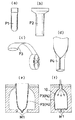
1 and 2 show one embodiment of the container volume reduction method according to the present invention. In this embodiment, the container body is formed by a blow molding method. FIG. 1 shows the steps up to the molding of the container body. FIG. 1A shows an example of injection blow molding, and a parison (P1) is a bottomed cylindrical member formed by injection molding. FIG. 1 (b) shows an example of direct blow molding, and the parison (P2) is a cylindrical one extruded from an extruder. FIG. 1 (c) shows a molding example using a tubular film produced by the film inflation method as a parison (P3). FIG. 1 (d) shows a molding example in which both edges of the composite film are heat-sealed into a cylindrical shape and supplied to a mold as a parison (P4).
[0037]
Then, as shown in FIG. 1 (e), the parison is put into a mold (M1). FIG. 1E shows a case where the parison (P3) (P4) shown in FIG. 1C or 1D is used. In this case, when the mold (M1) is closed, the parison is used. The openings of (P3) and (P4) are heat-sealed by being sandwiched between metal molds to form a bag. Although not shown in detail, required protrusions and ridges are formed on the inner surface of the mold (M1) so that folding guides such as score lines and rib lines are formed at predetermined portions of the container body to be molded. A concave groove or the like is formed in advance.
[0038]
In this way, as shown in FIG. 1 (f), sterilized air is blown into the parison (P3) (P4) from the upper end opening. Then, the parisons (P3) and (P4) expand and are brought into close contact with the inner surface of the mold (M1). As a result, a hollow container body (10) having a folding guide is formed.
[0039]
FIG. 2 shows steps after molding of the container body (10). As shown in FIG. 2A, a mouth member (3) is inserted into the opening of the container body (10) immediately after molding, and is fixed by heat sealing. The mouth member (3) has a fluid passage (not shown) penetrating vertically. Although not shown in FIG. 2, the mouth member (3) is connected to a closing member that is detachably engaged with the lower end opening to close the lower end opening of the fluid passage. When inserting the female member (3) into the opening of the container body (10), the fluid passage of the mouth member (3) is closed by the closing member. The opening and closing of the fluid passage of the mouth member (3) by the closing member can be performed by inserting or extracting a male member into or from the fluid passage.
[0040]
Next, as shown in FIG. 2B, the container body (10) is taken out of the mold (M1), and a vacuum nozzle (B) having the structure of the male member is provided in a fluid passage of the mouth member (3). ). Then, the closing member is disengaged from the lower end of the mouth member (3) to open the fluid passage, and through this fluid passage, the inside of the container body (10) is degassed under reduced pressure.
[0041]
Due to the internal decompression and deaeration, the container body (10) is folded flat along the folding guide as shown in FIG. 2 (c). Thereafter, when the vacuum nozzle (B) is pulled out from the fluid passage of the mouth member (3), the fluid passage is closed by the closing member, and the airtightness of the container body (10) is maintained.
[0042]
Further, as shown in FIG. 2 (d), the folded container body (10) is heated and molded by a press mold (M2) under heating at 60 to 80 ° C.
[0043]
In this way, as shown in FIG. 2 (e), a container is obtained in which the container body (10) is folded flat and maintained in a reduced volume form.
[0044]
FIG. 3 shows another embodiment of the container volume reducing method according to the present invention. In this embodiment, the steps up to the molding of the container body are the same as those in the above embodiment shown in FIG.
[0045]
In this embodiment, as shown in FIG. 3A, the container body (10) taken out of the mold after blow molding is heat-molded by a press mold (M2) under heating at 60 to 80 ° C. Then, the container body (10) is folded flat along the folding guide. In addition, the inside of the container body is evacuated accordingly.
[0046]
Next, as shown in FIG. 3 (b), an opening member (3) with a closing member is inserted into the opening of the folded container body (10) and fixed by heat sealing.
[0047]
Thus, as shown in FIG. 3C, a container (C) in which the container body (10) is folded flat and maintained in a reduced volume form is obtained.
[0048]
4 to 6 show a first embodiment of the container according to the present invention. The container (C1) is formed into a hollow shape by a blow molding method and has a container body (11) made of a thermoplastic resin having a folding guide (11A), and an airtight holding means provided at an opening of the container body (11). (21). The airtight holding means (21) has a fluid passage (3A) and is fixed to an opening of the container body (21). The mouth member (3) is detachably connected to the mouth member (3). 3A) and a closing member (4) for closing the same.
[0049]
As shown in FIG. 4A, the container body (11) includes a bottom (111) having a substantially rectangular cross section, a cylindrical body (112) rising from the periphery of the bottom (111), and a body (112). ) Comprises a substantially pyramid-shaped shoulder (113) connected to the upper end of the shoulder (113), and a neck (114) connected to the upper end of the shoulder (113) and having a circular cross section with an open upper end. A score line (11A) extending in the vertical direction is formed at the center of the width of the four side walls of the body (112). A plurality of score lines (11A) extending radially from the inner peripheral edge of the shoulder are formed. Although not shown, a plurality of score lines extending radially from the center of the bottom (111) are also formed at the bottom (111). The container body (11) is made by injection blow molding (see FIG. 1 (a)) or direct blow molding (see FIG. 1 (b)), and has no heat seal portion, There is no danger of.
[0050]
FIG. 4 (b) shows the container (C1) in a state where the volume is reduced by the method shown in FIG. The container body (11) is folded flat along the folding guide (11A), and its shape is maintained by the airtight holding means (21).
[0051]
As shown in detail in FIG. 5, the mouth member (3) includes a female member (3) having a fluid passage (3A) penetrating in the axial direction and fixed to an opening of the container body (11). The upper part of the female member (3) is fitted into the neck (114) of the container body (11) and fixed by heat sealing. An annular groove (31) is formed at a height intermediate portion of the outer peripheral surface of the female member (3). A small diameter portion (33) is provided at the lower end of the female member (3) via a tapered portion (32) whose diameter is gradually reduced downward. An annular inwardly protruding portion (34) is formed on the inner peripheral surface of the small diameter portion (33).
[0052]
The closing member (4) comprises a plug (4) capable of removably engaging the lower end of the female member (3) to close the lower end opening of the fluid passage (3A). The plug (4) is integrally formed at a portion near the lower end of the female member (3) via a connecting member (5). The plug (4) is substantially cylindrical with a bottom, and its inner peripheral surface is gradually reduced in diameter downward. The connecting member (5) is continuous with the center of the height of the outer peripheral surface of the plug (4). The upper half of the plug (4) is fitted into the small diameter portion (33) of the female member (3). At the upper end of the outer peripheral surface of the plug (4), an annular outer projection (41) is formed to engage with the annular inner projection (34) of the small diameter portion (33). An annular inwardly protruding portion (42) is formed at the upper end of the inner peripheral surface of the plug (4).
[0053]
The female member (3), the plug (4) and the connecting member (5) are integrally formed by, for example, an injection molding method using a thermoplastic resin.
[0054]
FIG. 4 (c) shows a container (C1) in which a container body (11) is filled with contents and made into a product form. The container body (11) is almost restored to the shape at the time of molding shown in FIG. The spout (6) is inserted and fixed in the fluid passage (3A) of the female member (3). A cap (7) is detachably mounted on the upper part of the spout (6).
[0055]
The spout (6) has the configuration of the male member described above. That is, as shown in detail in FIG. 6, the spout (6) includes a head (61) that engages with the plug (4), and a rod portion (62) that extends above the head (61). It is inserted into the fluid passageway (3A) of the member (3) so as to be able to be inserted and removed from above. A fluid passage (not shown) extending from the upper end to the lower end of the rod portion (62) of the male member (6) is formed, and a fluid around the fluid passage at the lower end of the rod portion (62) is formed. A through-hole (621) that allows the passage to communicate with the outside is formed. The outer peripheral surface of the head (61) is gradually reduced in diameter downward, and is fitted inside the plug (4). A horizontal annular groove (622) is formed at the center of the length of the outer peripheral surface of the rod (62), and the groove (622) is provided between the rod (62) and the fluid passage (3A) of the female member (3). A part of an O-ring (63) for sealing is fitted. A small diameter portion (624) is provided below the O-ring (63) on the outer peripheral surface of the rod portion (62) via a tapered portion (623). A plurality of the through holes (621) are formed in the small diameter portion (624) at intervals in the circumferential direction. An annular groove (625) that engages with the annular inwardly protruding portion (42) of the plug (4) is formed below the through hole (621) in the small diameter portion (624). The spout (6) further connects to the upper end of the rod-shaped portion (62) and is received on the upper surface of the female member (3). (651). Although not shown, the fluid passage of the spout (6) extends vertically through the large diameter portion (64) and the cap mounting portion (65) from the upper end of the rod portion (62), and the upper end of the spout (6) , From which the contents can be poured.
[0056]
The cap (7) is a screw cap having an inverted U-shape in vertical section, which is screwed into a cap mounting portion (65) with a male screw (651) of the spout (6).
[0057]
Here, the opening and closing operation of the fluid passage (3A) of the female member (3) by the plug (4) will be described with reference to FIGS.
[0058]
For example, when filling the container body (11) with the contents from the reduced volume configuration shown in FIG. 5, the same structure as the head (61) and the rod-shaped portion (62) of the spout (6) shown in FIG. The filling nozzle provided in the section is inserted into the fluid passage (3A) of the female member (3) from above. Then, the head (61) of the nozzle fits into the plug (4) engaged with the lower end of the female member (3), and then the plug (4) is pushed downward, and the female member (3) is pushed. It comes off from the lower end. When the nozzle is further inserted, the through hole (621) of the rod portion (62) is lowered to a position facing the inside of the container body (11). Thereby, the contents can be filled in the container body (11).
[0059]
When the filling is completed, the filling nozzle is raised. Then, the plug (4) is moved upward together with the head (61) of the nozzle, thereby engaging with the lower end of the female member (3) and opening the lower end of the fluid passage (3A) of the female member (3). Is closed. When the nozzle is further raised, its head (61) comes off the plug (4). As an actual process, the spout (6) is then inserted into the fluid passage (3A) of the female member (3) to obtain the state shown in FIG.
[0060]
When the inside of the molded container body (11) is degassed under reduced pressure (see FIG. 2 (b)), it is the same as the head (61) and the rod (62) of the spout (6) shown in FIG. By inserting a vacuum nozzle for decompression and deaeration provided with the above structure at the tip into the fluid passage (3A) of the female member (3) from above, the fluid passage (3A) of the female member (3) can be opened. Then, the container (C1) is brought into the state shown in FIG.
[0061]
FIG. 7 shows a second embodiment of the container according to the invention. As shown in FIG. 7A, in this embodiment, the container body (12) rises from the substantially elliptical bottom (121) and the periphery of the bottom (121), and both right and left sides are inwardly constricted. It has a torso (122) and a neck (124) having a circular cross section connected to the upper end of the torso (122) via a substantially horizontal shoulder (123). A score line (12A) extending vertically is formed at the center of the width of the front and rear walls of the trunk (122). Two score lines (12A) curved along both edges are formed on the left and right side walls of the body (122). An annular score line (12A) is formed at the center of the height of the trunk (122). A score line (12A) extending in the front-rear direction is also formed at the center in the left-right width of the bottom (121). The container body (12) is formed by a blow molding method (see FIG. 1 (c)) using a tubular film formed by a film inflation method as a parison. Therefore, a heat seal portion (125) is formed at a position corresponding to the opening of the parison in the container body (12). However, since the heat seal portion (125) is formed on the bottom portion (121) and the shoulder portion (123) as shown in FIG. 7, there is almost no danger of hand cutting or the like. In addition, in the case of the container body (12), there is an advantage that printing can be performed on the film.
[0062]
FIG. 7B shows the container (C2) in a state where the container main body (12) is folded flat and its shape is maintained by the airtight holding means (21). The container main body (12) is folded so that its trunk (122) is guided by the score lines (12A) on the left and right side walls and collapses in the front-rear direction, and is perpendicular to the front and rear walls in the trunk (122). Guided by the score line (12A) and the horizontal annular score line (12A) and the score line (12A) at the bottom (121), the central portion is folded toward the front wall side or the rear wall side so as to be depressed. The bottom (121) is folded toward the front wall or the rear wall of the body (122).
[0063]
The mouth member (3) with the plug (4) fixed to the opening of the container body (12) is the same as those of the first embodiment shown in FIGS.
[0064]
FIG. 7 (c) shows a container in which the contents are filled in a container body (12) to form a product. The container body (12) is almost restored to the shape at the time of molding shown in FIG. The spout (6) and cap (7) are also substantially the same as those of the first embodiment shown in FIGS.
[0065]
FIG. 8 shows a third embodiment of the container according to the present invention. As shown in FIG. 8 (a), in this embodiment, the container body (13) has a bottom portion (131) having a substantially rectangular oval shape, and a body rising from the periphery of the bottom portion (131) and having a closed upper end. (132). An opening (133) is formed at the center of the bottom (131). A score line (13A) extending in the vertical direction is formed at the center of the width of the left and right side walls of the trunk (132). Although not shown, a score line extending in the left-right direction is also formed at the center in the front-rear width of the bottom portion (131). The container body (13) is formed by a blow molding method (see FIG. 1 (d)) in which both edges of the composite film are heat-sealed and made into a cylindrical shape and used as a parison. Therefore, a heat seal portion (134) is formed at the bottom (131) of the container body (13) and at the center of the front and rear walls and the upper end of the body (132). There is little danger such as hand shortage since the user does not touch much when using C1). In addition, in the case of the container body (13), there is an advantage that a film can be printed and a vapor-deposited film can be used.
[0066]
FIG. 8 (b) shows the container (C3) in a state where the container body (13) is folded flat and its shape is maintained by the airtight holding means (21). The container body (13) is folded so that its trunk (132) is guided by the score lines (13A) on the left and right side walls and collapses in the front-rear direction, and the bottom (131) has a score in the center of its width. Guided by a line, it is folded back and forth.
[0067]
The mouth member (female member) (3) with the plug (4) is the same as that of the first embodiment shown in FIGS. 4 to 6, and is fixed to the opening (133) of the container body (13). .
[0068]
FIG. 8 (c) shows a container body (13) filled with contents and a spout (6A) connected to the female member (3). The container body (13) is almost restored to the shape at the time of molding shown in FIG. The spout (6A) is joined at its lower end to the bottom wall of a box-shaped holder (8) that opens upward. Although not shown, the lower end of the fluid passage of the spout (6A) penetrates the bottom wall of the holder (8) and opens to the lower surface. A plate-like lid (9) that can close the lower end opening of the fluid passage of the spout (6A) is attached to the holder (8) so that it can be opened and closed by a hinge. Other forms of the spout (6A) are substantially the same as the spout (6) of the first embodiment shown in FIGS.
[0069]
FIG. 8D shows a container (C3) in a product form. Although not shown, a spout (6A) is inserted and fixed in the fluid passage (3A) of the female member (3). The lower end of the container body (13) is accommodated in the holder (8).
[0070]
FIG. 9 shows a fourth embodiment of the container according to the present invention. As shown in FIG. 9 (a), the container body (14) has a bottom (141) which has a horizontal rectangular outline and is bent in a mountain shape at the center in the front-rear width, and rises from the periphery of the bottom (141). A body (142) having right and left side walls forming a triangle so that the front and rear thicknesses become gradually smaller as going upward, and a neck (143) having a circular cross section extending upward from the center of the upper end of the body (142). It has become. A vertical score line (14A) extending vertically is formed at the center of the width of the left and right side walls of the body (142). An oblique score line (14A) extending obliquely upward from the lower front and rear corners toward the vertical score line (14A) is formed below the left and right side walls of the body (142). This container body (14) is made by injection blow molding (see FIG. 1 (a)) or direct blow molding (see FIG. 1 (b)), and has no heat seal portion.
[0071]
FIG. 9 (b) shows the container (C4) in a state where the container body (14) is folded flat and its shape is maintained by the airtight holding means (21). The container body (14) is folded such that its body (142) is guided by the vertical score line (14A) and the oblique score line (14A) on the left and right side walls and collapses in the front-rear direction. The bottom part (141) is folded so that its front and rear parts overlap.
[0072]
The mouth member (3) with the plug (4) fixed to the opening of the container body (14) is the same as those of the first embodiment shown in FIGS.
[0073]
FIG. 9C shows a container (C4) in a product form. The container body (14) is almost restored to the shape at the time of molding shown in FIG. 9 (a) by being filled with the contents. The spout (6) and cap (7) are substantially the same as those of the first embodiment shown in FIGS.
[0074]
FIG. 10 shows a fifth embodiment of the container according to the present invention. As shown in FIG. 10 (a), the container body (15) has a substantially horizontal rectangular bottom portion (151) whose front and rear width bulges outward in a convex arc shape, and a tube rising from the periphery of the bottom portion (151). -Shaped torso (152), a horizontal shoulder (153) connected to the upper end of the torso (152) and having substantially the same shape as the bottom (151), and extending upward from the rear center of the shoulder (153). And a neck (154) having a circular cross section. Bellows (15A) are formed on the bottom (151), the right and left side walls of the trunk (152), and the shoulder (153), in which irregularities alternate in the front-rear direction. This container body (15) is obtained by the injection blow molding method (see FIG. 1A), and has no heat seal portion.
[0075]
FIG. 10B shows the container (C5) in a state where the container main body (15) is folded flat and its shape is maintained by the airtight holding means (21). The container main body (15) is flattened in the front-rear direction by folding the bellows portion (15A). The mouth member (3) with the plug (4) fixed to the neck (154) of the container body (15) is the same as those of the first embodiment shown in FIGS.
[0076]
FIG. 10C shows a container (C5) in a product form. The container main body (15) is almost restored to the shape at the time of molding shown in FIG. The spout (6) and cap (7) are substantially the same as those of the first embodiment shown in FIGS.
[0077]
FIG. 11 shows a sixth embodiment of the container according to the present invention. The container (C61) shown in FIG. 11A includes a rectangular box-shaped container body (161) having a small thickness in the front-rear direction. An opening (not shown) is formed at the right end of the top of the container body (161). The container body (161) is formed with a bellows portion (161A) in which irregularities are alternately arranged vertically, except for the upper end portion and the left end portion. Although not shown in detail, the mouth member with a plug, the spout and the cap (7) are substantially the same as those of the first embodiment shown in FIGS. This container (C61) can be flattened in the vertical direction by folding the bellows portion (161A) of the container body (161).
[0078]
The container (C62) shown in FIG. 11B has a form in which a plurality of containers (C61) shown in FIG. This container (C62) can also be flattened in the vertical direction by folding the bellows portion (162A) of the container body (162).
[0079]
In the container (C63) shown in FIG. 11C, the bellows portion (631A) formed in the container body (631) is configured such that the irregularities alternate in the front-rear direction. Otherwise, it is the same as the container (C62) shown in FIG. 11 (b). In the case of this container (C63), the bellows portion (631A) of the container body (631) can be flattened in the front-rear direction by being folded.
[0080]
It should be noted that the present invention is not limited to only the above-described embodiment, and it is needless to say that various changes can be made without departing from the gist of the present invention.
[Brief description of the drawings]
FIG. 1 is a cross-sectional view showing one embodiment of a method for reducing the volume of a container according to the present invention and showing steps up to the molding of a container body.
FIG. 2 is a cross-sectional view showing steps after molding of the container body in the embodiment.
FIG. 3 is a cross-sectional view showing another embodiment of the method for reducing the volume of a container according to the present invention, which sequentially shows steps after molding of the container body.
FIG. 4 shows a first embodiment of the container according to the present invention and is a perspective view of the container at the time of molding, volume reduction, and after filling.
FIG. 5 is an enlarged longitudinal sectional view of a main part of the container in the state shown in FIG. 4 (b).
FIG. 6 is an enlarged vertical sectional view of a main part of the container in the state shown in FIG. 4 (c).
FIG. 7 shows a second embodiment of the container according to the present invention and is a perspective view of the container during molding, during volume reduction, and after filling.
FIG. 8 shows a third embodiment of the container according to the present invention and is a perspective view of the container at the time of molding, at the time of volume reduction, and after filling.
FIG. 9 shows a fourth embodiment of the container according to the present invention and is a perspective view of the container at the time of molding, volume reduction, and after filling.
FIG. 10 shows a fifth embodiment of the container according to the present invention, and is a perspective view of the container during molding, during volume reduction, and after filling.
FIG. 11 is a perspective view showing a sixth embodiment of the container according to the present invention.
[Explanation of symbols]
(M1): Mold for blow molding
(M2): Heat forming mold
(B): Vacuum nozzle
(C) (C1) (C2) (C3) (C4) (C5) (C61) (C62) (C63): Container
(10) (11) (12) (13) (14) (15) (161) (162) (163): Container main body
(11A) (12A) (13A) (14A): score line (folding guide)
(15A) (161A) (162A) (163A): bellows (folding guide)
(21): Airtightness maintaining means
(3): mouth member (female member)
(3A): Fluid passage
(4): Plug (closing member)
(6): Spout (male member)
(61): Head
(62): rod-shaped part
(621): Through-hole
Claims (9)
Priority Applications (1)
| Application Number | Priority Date | Filing Date | Title |
|---|---|---|---|
| JP2002343746A JP2004175406A (en) | 2002-11-27 | 2002-11-27 | Container and method of reducing its volume |
Applications Claiming Priority (1)
| Application Number | Priority Date | Filing Date | Title |
|---|---|---|---|
| JP2002343746A JP2004175406A (en) | 2002-11-27 | 2002-11-27 | Container and method of reducing its volume |
Publications (2)
| Publication Number | Publication Date |
|---|---|
| JP2004175406A true JP2004175406A (en) | 2004-06-24 |
| JP2004175406A5 JP2004175406A5 (en) | 2005-12-22 |
Family
ID=32705463
Family Applications (1)
| Application Number | Title | Priority Date | Filing Date |
|---|---|---|---|
| JP2002343746A Pending JP2004175406A (en) | 2002-11-27 | 2002-11-27 | Container and method of reducing its volume |
Country Status (1)
| Country | Link |
|---|---|
| JP (1) | JP2004175406A (en) |
Cited By (6)
| Publication number | Priority date | Publication date | Assignee | Title |
|---|---|---|---|---|
| JP2009045143A (en) * | 2007-08-16 | 2009-03-05 | Nipro Corp | Blow-molded plastic infusion container |
| EP2067464A1 (en) * | 2006-09-25 | 2009-06-10 | Nipro Corporation | Blow-molded plastic infusion container |
| JP5292093B2 (en) * | 2006-07-27 | 2013-09-18 | 株式会社パックプラス | Pouch and method for producing the same |
| JP2016531774A (en) * | 2013-08-12 | 2016-10-13 | プリントパック イリノイ インコーポレイテッド | Method for producing a blow molded container with a multi-barrier layer |
| WO2017148570A1 (en) * | 2016-02-29 | 2017-09-08 | Kocher-Plastik Maschinenbau Gmbh | Container consisting of plastic material, and method for producing a container of this type |
| JP2018034352A (en) * | 2016-08-30 | 2018-03-08 | キョーラク株式会社 | Method for producing foam molded body |
-
2002
- 2002-11-27 JP JP2002343746A patent/JP2004175406A/en active Pending
Cited By (13)
| Publication number | Priority date | Publication date | Assignee | Title |
|---|---|---|---|---|
| JP5292093B2 (en) * | 2006-07-27 | 2013-09-18 | 株式会社パックプラス | Pouch and method for producing the same |
| EP2067464A1 (en) * | 2006-09-25 | 2009-06-10 | Nipro Corporation | Blow-molded plastic infusion container |
| EP2067464A4 (en) * | 2006-09-25 | 2013-12-25 | Nipro Corp | Blow-molded plastic infusion container |
| US8864735B2 (en) | 2006-09-25 | 2014-10-21 | Nipro Corporation | Blow-molded plastic infusion container |
| JP2009045143A (en) * | 2007-08-16 | 2009-03-05 | Nipro Corp | Blow-molded plastic infusion container |
| US10293539B2 (en) | 2013-08-12 | 2019-05-21 | Printpack Illinois, Inc. | Method for manufacturing multi-barrier layer blow molded containers |
| JP2016531774A (en) * | 2013-08-12 | 2016-10-13 | プリントパック イリノイ インコーポレイテッド | Method for producing a blow molded container with a multi-barrier layer |
| WO2017148570A1 (en) * | 2016-02-29 | 2017-09-08 | Kocher-Plastik Maschinenbau Gmbh | Container consisting of plastic material, and method for producing a container of this type |
| CN108697574A (en) * | 2016-02-29 | 2018-10-23 | 科赫尔塑料机械制造有限公司 | The container made of plastic material and the method for manufacturing such container |
| RU2720965C2 (en) * | 2016-02-29 | 2020-05-15 | Кохер-Пластик Машиненбау Гмбх | Plastic container and method for manufacturing of container of such type |
| US11096866B2 (en) | 2016-02-29 | 2021-08-24 | Kocher-Plastik Maschinenbau Gmbh | Container consisting of plastic material, and method for producing a container of this type |
| CN108697574B (en) * | 2016-02-29 | 2021-09-21 | 科赫尔塑料机械制造有限公司 | Container made of plastic material and method for manufacturing such a container |
| JP2018034352A (en) * | 2016-08-30 | 2018-03-08 | キョーラク株式会社 | Method for producing foam molded body |
Similar Documents
| Publication | Publication Date | Title |
|---|---|---|
| JP6847706B2 (en) | Preform assembly for double-structured container molding | |
| ES2273866T3 (en) | MOLDED CONTAINER0 BY BLOWING AND CLOSING COVER, AND PROCEDURE AND APPARATUS FOR THE MANUFACTURE OF THE SAME. | |
| US11155390B2 (en) | Coupled structure between pouring spout of refill container and pouring unit of packaging container | |
| WO2017098867A1 (en) | Double walled container and manufacturing method for same | |
| CN110740939A (en) | Laminated peeling container | |
| US5392950A (en) | Plastic container with a completely sealed handle | |
| US10961025B2 (en) | Pouring spout of container | |
| JP2004175406A (en) | Container and method of reducing its volume | |
| JPH10506075A (en) | Thermoformable material container with closure | |
| US20050051574A1 (en) | Low profile cap for stand-up tube | |
| JP4678664B2 (en) | Small capacity container with twist-off port | |
| EP1870345B1 (en) | Blow-molded container in the shape of a pouch | |
| JP2018016317A (en) | Tube | |
| JP4743853B2 (en) | container | |
| JP2021028153A (en) | Preform, synthetic resin container, and method for manufacturing synthetic resin container | |
| JP4253870B2 (en) | Manufacturing method of molded filling container | |
| JP2021127164A (en) | Double container | |
| JP6850531B2 (en) | Double container and its manufacturing method | |
| JPH08244101A (en) | Manufacture of aseptic container | |
| JP2007045473A (en) | Airless container | |
| JP2002302112A (en) | Tubular thin-walled blow molding bottle | |
| JP2022071767A (en) | Delamination container, and container with content using the same | |
| JP2021187512A (en) | Double container | |
| JP4107378B2 (en) | Pouch-shaped blow molded container | |
| JP4934182B2 (en) | Manufacturing method of free-standing bags |
Legal Events
| Date | Code | Title | Description |
|---|---|---|---|
| A521 | Written amendment |
Free format text: JAPANESE INTERMEDIATE CODE: A523 Effective date: 20051104 |
|
| A621 | Written request for application examination |
Free format text: JAPANESE INTERMEDIATE CODE: A621 Effective date: 20051104 |
|
| A977 | Report on retrieval |
Free format text: JAPANESE INTERMEDIATE CODE: A971007 Effective date: 20080910 |
|
| A131 | Notification of reasons for refusal |
Free format text: JAPANESE INTERMEDIATE CODE: A131 Effective date: 20080930 |
|
| A521 | Written amendment |
Free format text: JAPANESE INTERMEDIATE CODE: A523 Effective date: 20081121 |
|
| A02 | Decision of refusal |
Free format text: JAPANESE INTERMEDIATE CODE: A02 Effective date: 20090728 |