JP4832178B2 - Variable capacity swash plate type hydraulic rotating machine - Google Patents
Variable capacity swash plate type hydraulic rotating machine Download PDFInfo
- Publication number
- JP4832178B2 JP4832178B2 JP2006172367A JP2006172367A JP4832178B2 JP 4832178 B2 JP4832178 B2 JP 4832178B2 JP 2006172367 A JP2006172367 A JP 2006172367A JP 2006172367 A JP2006172367 A JP 2006172367A JP 4832178 B2 JP4832178 B2 JP 4832178B2
- Authority
- JP
- Japan
- Prior art keywords
- piston
- swash plate
- servo piston
- control pressure
- rotating machine
- Prior art date
- Legal status (The legal status is an assumption and is not a legal conclusion. Google has not performed a legal analysis and makes no representation as to the accuracy of the status listed.)
- Active
Links
Images


Description
本発明は、例えばホイールローダに搭載される油圧ポンプ等の可変容量型斜板式液圧回転機に関するものである。 The present invention relates to a variable displacement swash plate type hydraulic rotating machine such as a hydraulic pump mounted on a wheel loader, for example.
可変容量型斜板式液圧回転機は、ケーシング内に回転軸に連結したシリンダブロックを設け、このシリンダブロックには円周方向に向けて所定ピッチ間隔をもって複数のシリンダを装着する構成としたものである。そして、シリンダブロックに形成される各シリンダ内にはそれぞれピストンが摺動可能に設けられており、各ピストンにはシューが設けられ、これらのシューは斜板に摺接している。 A variable capacity swash plate type hydraulic rotating machine has a structure in which a cylinder block connected to a rotating shaft is provided in a casing, and a plurality of cylinders are attached to the cylinder block at predetermined pitch intervals in a circumferential direction. is there. A piston is slidably provided in each cylinder formed in the cylinder block, and a shoe is provided in each piston, and these shoes are in sliding contact with the swash plate.
この液圧回転機において、回転軸をエンジン等の動力源に連結して、この回転軸と共にシリンダブロックを回転駆動すると、斜板を摺動するピストンがシリンダ内で往復運動を行うことにより、シリンダ内に作動油を吸い込んで、ピストンにより作動油を加圧して吐出することになり、油圧ポンプとして機能する。また、圧油をシリンダ内に導入すると、ピストンを押動することになる結果、回転軸を連結したシリンダブロックが回転駆動されることになり、油圧モータとして機能する。 In this hydraulic rotating machine, when the rotating shaft is connected to a power source such as an engine and the cylinder block is driven to rotate together with the rotating shaft, the piston sliding on the swash plate performs reciprocating motion in the cylinder. The hydraulic oil is sucked into the cylinder, and the hydraulic oil is pressurized and discharged by the piston and functions as a hydraulic pump. Further, when the pressure oil is introduced into the cylinder, the piston is pushed, and as a result, the cylinder block connected to the rotating shaft is rotationally driven, and functions as a hydraulic motor.
斜板は、その角度を変化させることによって、つまり傾転制御を行うことによって、ピストンによる押し退け容積を可変にするものであり、油圧ポンプとして機能させる場合には、その吐出容量が変化することになる。斜板の傾転制御は、この斜板の摺動面がピストンの軸線と直交する方向となる状態(中立位置)から所定の角度に傾斜させるように制御することであり、一方向にのみ傾転させる構成としたものと、両方向に傾転させる構成としたものとがある。 The swash plate changes the displacement by the piston by changing its angle, that is, by performing tilt control. When the swash plate functions as a hydraulic pump, its discharge capacity changes. Become. The tilt control of the swash plate is a control so that the sliding surface of the swash plate is inclined at a predetermined angle from a state (neutral position) perpendicular to the axis of the piston. There are ones that are configured to roll, and ones that are configured to tilt in both directions.
両方向に傾転させる可変容量型斜板式液圧回転機は、例えば特許文献1に記載されているように、斜板から延在させた斜板傾転部材をサーボピストンに連結し、このサーボピストンをピストン収納部に摺動可能に設けたものであり、サーボピストンの両端部はそれぞれ制御圧室に臨ませている。そして、一方の制御圧室に制御圧が導かれ、他方の制御圧室をタンク圧とすることによって、サーボピストンの両端受圧面に差圧が生じ、このサーボピストンがピストン収納部の内面に沿って摺動変位することになる。また、サーボピストンには中立位置への復帰用のばねを作用させて、両制御圧室に制御圧が作用しないときには、サーボピストンは中立位置に保持されることになる。
前述したように、サーボピストンには斜板の斜板傾転部材が連結されるが、この斜板傾転部材の連結位置はサーボピストンの中間位置である。そして、斜板はケーシング内に配設されるが、この斜板の配設位置はタンク圧に保持されている。従って、サーボピストンの両端が臨む制御圧室の間の部位の外周部はタンク圧となったタンク圧領域である。このために、サーボピストンが中立位置からいずれかの傾転位置に傾転変位させたときには、サーボピストンの外周面はタンク圧領域を挟んだ両側の部位のうち、一方側では制御圧が作用しているので、この制御圧によりサーボピストンの外周面に作動油が流入して、ピストン収納部内面との間に潤滑油膜が形成されるが、タンク圧領域とタンク圧側の制御圧室との間の部位において、サーボピストンの外周面とピストン収納部の内周面との間には作動油が供給されないことになる。 As described above, the swash plate tilting member of the swash plate is connected to the servo piston, and the connecting position of the swash plate tilting member is an intermediate position of the servo piston. The swash plate is disposed in the casing, and the position of the swash plate is maintained at tank pressure. Therefore, the outer peripheral portion of the portion between the control pressure chambers facing both ends of the servo piston is a tank pressure region where the tank pressure becomes the tank pressure. For this reason, when the servo piston is tilted and displaced from the neutral position to one of the tilt positions, the outer surface of the servo piston is subjected to the control pressure on one side of both sides of the tank pressure region. Therefore, hydraulic oil flows into the outer peripheral surface of the servo piston due to this control pressure, and a lubricating oil film is formed between the inner surface of the piston housing part, but between the tank pressure region and the control pressure chamber on the tank pressure side. In this part, hydraulic fluid is not supplied between the outer peripheral surface of the servo piston and the inner peripheral surface of the piston housing portion.
前述したように、シリンダブロックが回転すると、ピストンがシリンダ内を往復動することから、液圧回転機の作動中には、斜板を振動させることになり、この斜板の振動は斜板傾転部材を介してサーボピストンに伝達されて、サーボピストンがピストン収納部に対して微小振動することになる。その結果、サーボピストンの外周面とピストン収納部の内周面との間において、制御圧が作用する側とタンク圧領域との間は作動油が流入するから潤滑性能が維持されるが、タンク圧側とタンク圧領域との間の部位には潤滑機能が得られないことになる。その結果、前述したサーボピストンの振動等によりサーボピストンとピストン収納部との間の摺動面にフレッティングや凝着が発生したり、磨耗が進行したりする等といった問題点がある。また、サーボピストンとピストン収納部との間の接触面積を大きくすれば、このような不都合をある程度は抑制できるが、そうすると、サーボピストンの軸線方向の長さを必要以上長くしなければならず、このために液圧回転機全体が大型化する等といった不都合が生じることになる。 As described above, when the cylinder block rotates, the piston reciprocates in the cylinder, so that the swash plate is vibrated during the operation of the hydraulic rotating machine. The servo piston is transmitted to the servo piston via the rolling member, and the servo piston slightly vibrates with respect to the piston housing portion. As a result, between the outer peripheral surface of the servo piston and the inner peripheral surface of the piston housing portion, hydraulic oil flows between the side on which the control pressure acts and the tank pressure region, so that the lubricating performance is maintained. A lubrication function cannot be obtained at a portion between the pressure side and the tank pressure region. As a result, there is a problem that fretting or adhesion occurs on the sliding surface between the servo piston and the piston housing portion due to the vibration of the servo piston described above, or wear progresses. Further, if the contact area between the servo piston and the piston housing portion is increased, such inconvenience can be suppressed to some extent, but then the length of the servo piston in the axial direction must be increased more than necessary, For this reason, inconveniences such as an increase in the size of the entire hydraulic rotating machine occur.
本発明は以上の点に鑑みてなされたものであって、その目的とするところは、サーボピストンとピストン収納部との間の接触面積を増大することなく、その間の摺動を円滑に行わせて、フレッティングや凝着の抑制及び磨耗の低減を図ることにある。 The present invention has been made in view of the above points, and an object of the present invention is to smoothly slide between the servo piston and the piston housing portion without increasing the contact area. Therefore, fretting and adhesion are suppressed and wear is reduced.
前述した目的を達成するために、本発明は、斜板式液圧回転機の斜板を傾転駆動するために、この斜板に連結して設けたサーボピストンをピストン収納部内に摺動可能に設け、このピストン収納部には前記サーボピストンに制御圧を作用させる一対の制御圧室を形成し、かつその軸線方向の中間部の外周部はタンク圧領域となった可変容量型斜板式液圧回転機であって、前記サーボピストンには、少なくとも一方の制御圧室と連通する導油通路を穿設し、前記導油通路は、前記ピストン収納部の内面であって、前記タンク圧領域の位置を越えた位置で前記サーボピストンの摺動面部に開口させる構成としたことをその特徴とするものである。
In order to achieve the above-described object, the present invention enables a servo piston connected to the swash plate to slide in the piston housing portion in order to drive the swash plate of the swash plate type hydraulic rotating machine to tilt. A variable capacity swash plate type hydraulic pressure chamber in which a pair of control pressure chambers for applying a control pressure to the servo piston is formed in the piston housing portion , and an outer peripheral portion of an intermediate portion in the axial direction is a tank pressure region In the rotating machine, the servo piston is provided with an oil guide passage communicating with at least one control pressure chamber, and the oil guide passage is an inner surface of the piston housing portion, and is formed in the tank pressure region. It is characterized in that it is configured to open to the sliding surface portion of the servo piston at a position beyond the position .
導油通路をサーボピストンの摺動面に開口させるのは、この摺動面に潤滑膜を形成するためである。そして、このように供給される作動油は制御圧室からの漏れ流量となることから、制御性の観点から、供給油量は潤滑機能を発揮するのに必要最小限に止めるようにするのが望ましく、通路断面積は小さいものとなる。導油通路はサーボピストンの軸線方向に向けた通路の部分と、これと直交する方向の通路部分とからなり、比較的長い通路となる。導油通路の通路断面積を調整する必要があるが、この摺動面への供給流量を正確に制御するために、導油通路の途中に絞り部を設けるようにするのが望ましい。特に、サーボピストンの軸線と直交する方向の通路部分を絞り部とするのが最も望ましい。 The reason why the oil guide passage is opened in the sliding surface of the servo piston is to form a lubricating film on the sliding surface. And since the hydraulic oil supplied in this way becomes a leakage flow rate from the control pressure chamber, from the viewpoint of controllability, the amount of supplied oil should be kept to the minimum necessary to perform the lubrication function. Desirably, the cross-sectional area of the passage is small. The oil guide passage is composed of a passage portion directed in the axial direction of the servo piston and a passage portion orthogonal to the passage portion, and is a relatively long passage. Although it is necessary to adjust the cross-sectional area of the oil guide passage, it is desirable to provide a throttle portion in the middle of the oil guide passage in order to accurately control the flow rate supplied to the sliding surface. In particular, it is most desirable to use the passage portion in the direction orthogonal to the axis of the servo piston as the throttle portion.
ピストン収納部には制御圧室が複数形成されるが、最も通常の構成では、サーボピストンの両端がそれぞれ臨む制御圧室を左右一対形成することになる。サーボピストンは斜板傾転部材等を介して斜板と連結される関係から、斜板及びシリンダブロックが装着されているケーシングの内部のタンク圧領域とこの部位とが連通状態となる。つまり、サーボピストンの軸線方向における中間部分の外周部はタンク圧領域に配置される。制御圧室からの制御圧を導く導油通路は、従って、制御圧室への連通部から、このタンク圧領域の位置を越えた位置の外周面に開口させるようにする。例えば、ホイールローダの油圧ポンプとして構成する場合には、サーボピストンの両端に形成される制御圧室のうち、一方側の制御圧室に制御圧を導入したときには車両が前進し、反対側の制御圧室に制御圧が導入されると、車両が後進する、というように制御する構成とすることができる。車両の前進時には高い制御圧を導入して、高速走行を可能とするが、後進時にはあまり速度を高くしないのが一般的である。そこで、サーボピストンには2箇所の導油通路を形成して、それぞれの制御圧室に接続する構成とすることもできるが、少なくとも前進方向に斜板を傾転させるための制御圧が作用する制御圧室に連通させる導油通路は必須のものとし、後進側の制御圧室には必ずしも導油通路を連通させなくても良い。 A plurality of control pressure chambers are formed in the piston housing portion. In the most usual configuration, a pair of left and right control pressure chambers facing both ends of the servo piston are formed. Since the servo piston is connected to the swash plate via a swash plate tilting member or the like, the tank pressure region inside the casing on which the swash plate and the cylinder block are mounted and this portion are in communication with each other. That is, the outer peripheral portion of the intermediate portion in the axial direction of the servo piston is disposed in the tank pressure region. Therefore, the oil guide passage for guiding the control pressure from the control pressure chamber is opened from the communicating portion to the control pressure chamber to the outer peripheral surface at a position beyond the position of the tank pressure region. For example, when configured as a hydraulic pump for a wheel loader, the vehicle moves forward when the control pressure is introduced into one of the control pressure chambers formed at both ends of the servo piston, and the control on the opposite side. When a control pressure is introduced into the pressure chamber, the vehicle can be controlled to move backward. A high control pressure is introduced when the vehicle is moving forward to enable high-speed traveling, but generally the speed is not so high when the vehicle is moving backward. Therefore, it is possible to form two oil guide passages in the servo piston and connect them to the respective control pressure chambers, but at least a control pressure for tilting the swash plate in the forward direction acts. An oil guide passage communicating with the control pressure chamber is essential, and the oil guide passage does not necessarily need to communicate with the control pressure chamber on the reverse side.
既に説明したように、導油通路はサーボピストンの外周面とピストン収納部の内周面との間を潤滑するためのものであるから、作動油はサーボピストンの外周面の全周に供給されなければならない。このためには、サーボピストンの外周面に円環状の溝を形成して、この円環状の溝に導油通路を開口させるようにするのが望ましい。サーボピストンの左右両側に制御圧室を設けた場合、一方の制御圧室に制御圧が導入されているときには、他方の制御圧室はタンク圧となっている。従って、制御圧が作用している側の導油通路はピストン収納部の摺動面に開口することが必要であるが、このタンク圧となる側の制御圧室からの導油通路はタンク圧領域と連通させるように構成することもでき、サーボピストンの軸線方向の長さをその分だけ短縮できる。ただし、傾転制御を行う際に、低圧側の制御圧室にある程度の背圧を生じさせることによって、サーボピストンを安定的に動作させるようにするのが望ましい。このために、制御圧室に接続したタンクへの還流路には、絞りを設ける構成することになる。この場合に、絞りを介してタンクと接続される経路に加えて導油通路からなる経路が開かれていると、絞りとしての機能が低下することになる。ところで、サーボピストンの両端に中立位置への復帰用のばねが作用する構成とするが、このばねのばね座を導油通路の接続部を覆うことができる構成とする。そして、いずれかの制御圧室が高圧になり、サーボピストンがピストン収納部内を摺動する際には、高圧側となる制御圧室側のばね座はサーボピストンの端面から離間し、低圧側となる制御圧室側のばね座はサーボピストンの端面に圧接する。そこで、このばね座でサーボピストンに接続する導油通路を密閉させることができる。 As already explained, since the oil guide passage is for lubricating between the outer peripheral surface of the servo piston and the inner peripheral surface of the piston housing portion, the hydraulic oil is supplied to the entire outer periphery of the servo piston. There must be. For this purpose, it is desirable to form an annular groove on the outer peripheral surface of the servo piston so that the oil guide passage is opened in the annular groove. When the control pressure chambers are provided on both the left and right sides of the servo piston, when the control pressure is introduced into one of the control pressure chambers, the other control pressure chamber has a tank pressure. Therefore, the oil guide passage on the side on which the control pressure is applied needs to open to the sliding surface of the piston housing portion, but the oil guide passage from the control pressure chamber on the side that becomes the tank pressure is the tank pressure. It can also be configured to communicate with the region, and the length of the servo piston in the axial direction can be shortened accordingly. However, when tilt control is performed, it is desirable to cause the servo piston to operate stably by generating a certain amount of back pressure in the control pressure chamber on the low pressure side. For this reason, a throttle is provided in the return path to the tank connected to the control pressure chamber. In this case, if a path including an oil guide passage is opened in addition to a path connected to the tank via the throttle, the function as a throttle is reduced. By the way, although it is set as the structure which the spring for a return to a neutral position acts on the both ends of a servo piston, it is set as the structure which can cover the connection part of an oil guide passage with the spring seat of this spring. When one of the control pressure chambers becomes high pressure and the servo piston slides in the piston housing portion, the spring seat on the control pressure chamber side which is the high pressure side is separated from the end surface of the servo piston, The control pressure chamber side spring seat is in pressure contact with the end face of the servo piston. Therefore, the oil guide passage connected to the servo piston can be sealed with this spring seat.
斜板を傾転させ、また所定の傾転状態に保持する際に、サーボピストンの外周面とピストン収納部の内面と摺動を円滑に行わせて、その間の摺動面積を必要以上大きくすることなく、フレッティングや凝着を抑制し、かつ磨耗の低減を図ることができる。 When the swash plate is tilted and held in a predetermined tilted state, the outer surface of the servo piston and the inner surface of the piston housing part are smoothly slid to increase the sliding area between them more than necessary. Therefore, fretting and adhesion can be suppressed and wear can be reduced.
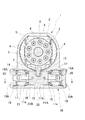
以下、図面に基づいて本発明の実施の形態について説明する。図面において、図1は斜板式液圧回転機の断面図であり、図2は図1のX−X断面図、図3は作動状態を示す図2と同様の断面図である。 Hereinafter, embodiments of the present invention will be described with reference to the drawings. In the drawings, FIG. 1 is a sectional view of a swash plate type hydraulic rotating machine, FIG. 2 is a sectional view taken along line XX of FIG. 1, and FIG. 3 is a sectional view similar to FIG.
これらの図において、1は液圧回転機の本体ケーシングであって、この本体ケーシング1内には斜板2と、シリンダブロック3とが設けられている。シリンダブロック3には円周方向に複数(図1においては9個)のシリンダ4が形成されており、各シリンダ4にはピストン5が摺動可能に装着されている。また、シリンダブロック3には回転軸6が接続されており、この回転軸6をエンジン等の動力源により回転駆動することによって、シリンダブロック3が回転することになる。そして、斜板2をシリンダ4の軸線と直交する方向から所定角度傾転させた状態で、回転軸6によりシリンダブロック3を回転駆動すると、シリンダ4内でピストン3が往復動することになり、斜板2の傾転角に応じた押し退け容積を有するポンプ作用を行うことになる。
In these drawings,
斜板2には斜板傾転部材7が延在されており、この斜板傾転部材7を図1の左右方向に回動させることによって、斜板2の傾転制御が行われる。斜板傾転部材7を駆動するために、本体ケーシング1には傾転制御機構10が連結して設けられている。傾転制御機構10はピストン収納部11を有し、このピストン収納部11にはサーボピストン12が設けられており、このサーボピストン12に斜板傾転部材7が連結して設けられている。斜板傾転部材7とサーボピストン12との連結部の構成としては、サーボピストン12には円弧状凹部13を形成し、この円弧状凹部13には斜板傾転部材7の先端に設けた軸受部材14を摺動可能に嵌合させている。
A swash
サーボピストン12はピストン収納部11の内面に沿って軸線方向に移動可能に装着されている。そして、ピストン収納部11の両端には蓋体15A,15Bが装着されて、サーボピストン12の両端面とそれぞれの蓋体15A,15Bとの間には制御圧室16A,16Bが形成されている。そして、サーボピストン12の両端面と蓋体15A,15Bとの間には、中立位置への復帰用のばね17が設けられている。ばね17の両端はばね座18,19に当接しており、一方のばね座18はサーボピストン12の端面と共にピストン収納部11に形成した段差部11aに当接している。また、他方のばね座19は蓋体15Aまたは15Bに当接している。なお、20はばね座19をサーボピストン12の軸線方向の位置からずれないようにするための調芯部材である。
The
ここで、サーボピストン12のうち、制御圧室16A,16Bに臨んでいるのはその両端面であって、このサーボピストン12の外周面において、ピストン収納部11の内周面と摺接しているのは両端部から所定の長さ分で、ピストン収納部11の内周面のうち、符号21A,21Bで示した部位がサーボピストン12への摺動部である。また、これら両摺動部21A,21B間の部位には凹状部11bが形成されており、この凹状部11bの一部は本体ケーシング1の内部に開口し、斜板傾転部材7はこの連通部分からピストン収納部11内に延在されて、サーボピストン12の円弧状凹部13と係合している。また、サーボピストン12の外周面も、その中間部分が縮径されている。これによって、サーボピストン12の中間縮径部とピストン収納部11における摺動部21A,21B間の凹状部11bとの間には、本体ケーシング1の内部と連通するタンク圧領域22が形成されている。
Here, the
傾転制御機構10を構成する制御圧室16A,16Bには、図2に示したように、それぞれ油圧配管23A,23Bが接続されており、これら両油圧配管23A,23Bは制御弁24を介して、油圧ポンプ25からの高圧配管26または作動油タンク27への低圧配管28が切り換え接続される。そして、低圧配管27には背圧を発生させるための絞り29が設けられている。
As shown in FIG. 2, hydraulic piping 23 A and 23 B are connected to the
さらに、サーボピストン12の両端部から軸線方向に向けて導油通路30A,30Bが穿設して設けられている。これら両導油通路30A,30Bはタンク圧領域22に臨む縮径部を越える位置まで軸線方向に向けて延在されており、これら導油通路30A,30Bの端部には絞り通路31A,31Bが連通している。そして、これら両絞り通路31A,31Bはサーボピストン12の軸線と直交する方向に向けられたものであり、このサーボピストン12の外周面に形成した円環状溝32A,32Bに接続されており、円環状溝32Aは摺動部21Bに、また円環状溝32Bは摺動部21Aに開口している。
Further,
以上のように構成される斜板式液圧回転機は、例えばシリンダブロック3に連結した回転軸6を回転駆動することによりシリンダ4内に吸い込んだ作動油をピストン5の往復動により加圧して吐出する油圧ポンプとして機能し、またはシリンダブロック3のシリンダ4にポンプポートからの圧油を供給することによって、回転軸6を回転駆動する油圧モータとして機能する。
The swash plate type hydraulic rotating machine configured as described above pressurizes and discharges the hydraulic oil sucked into the
この斜板式液圧回転機は可変容量型のものであり、油圧ポンプとして機能させる場合において、斜板2を傾転させることにより、吐出流量が変化する。このために設けられているのが傾転制御機構10であり、この傾転制御機構10にはサーボピストン12を有し、このサーボピストン12の両端に設けた制御圧室16A,16Bのいずれか一方に油圧ポンプ25からの制御圧を作用させ、他方を作動油タンク27に接続することによって、斜板2が傾転制御される。
This swash plate type hydraulic rotating machine is of a variable displacement type, and when it functions as a hydraulic pump, the discharge flow rate is changed by tilting the
図2の状態では、制御弁24は中立位置となって、両制御圧室16A,16Bは共に低圧配管28を介して作動油タンク27に接続されている。その結果、サーボピストン12は、その両端面に作用するばね17,17により中立位置となり、このサーボピストン12に接続した斜板傾転部材7により斜板2がいずれの方向にも傾転せず、シリンダブロック3の軸線と直交する中立位置に保持される。従って、回転軸6を回転させて、シリンダブロック3を回転させてもピストン5はストロークしない。
In the state of FIG. 2, the
この状態から、図3に示したように、制御弁24を右側の切換位置に切り換えると、制御圧室16Aが油圧ポンプ25に接続されて高圧油が導入される。一方、制御圧室16Bは作動油タンク27に接続されて低圧状態になる。その結果、これら制御圧室16A,16B間の差圧によって、サーボピストン12がピストン収納部11との摺動部21A,21Bに沿って摺動変位することになり、これにより斜板傾転部材7が左方向に回動することになり、斜板2が所定の角度傾動することになり、この状態で回転軸6によりシリンダブロック3を回転駆動すると、ピストン5がシリンダ4内でこの傾転角に応じた量だけストロークすることになり、それに相当する押し退け容積分の圧油が吐出される。また、制御弁24を左側の切換位置に切り換えたときには、制御圧室16Bが高圧となり、制御圧室16Aが低圧となるので、サーボピストン12は前述とは逆方向に変位することになり、斜板2は前述とは反対方向に傾動することになる。
From this state, as shown in FIG. 3, when the
しかも、この液圧回転機はピストン5を有するものであり、従ってピストン5が死点位置を通過する毎に振動が発生することになる。この振動はシリンダブロック3から斜板2及び斜板傾転部材7を介してサーボピストン12に伝達される。このために、液圧回転機が作動する間、サーボピストン12はピストン収納部11の内面に対して常に微振動することになる。つまり、斜板2の傾転時及び液圧回転機が作動している間は、サーボピストン12の外周面とピストン収納部11の内周面とは常に摺接する状態となる。
In addition, this hydraulic rotating machine has the
ここで、サーボピストン12は、その中間部がタンク圧領域22であって、このタンク圧領域22の両側がピストン収納部11の内周面との摺動部21A,21Bとなっているので、サーボピストン12は、これら両摺動部21A,21Bに沿って摺動する。制御圧室16Aは油圧ポンプ25から供給される高圧油が導入されているので、この高圧油が摺動部21Aに流入して、潤滑膜が形成される。従って、サーボピストン12の作動時には、摺動部21A側では円滑に摺動し、磨耗等が発生するおそれはない。
Here, the
一方、摺動部21B側は、摺動部21Aとはタンク圧領域22により隔離されており、しかも制御圧室16Bはタンク圧となっている。従って、摺動部21B側には作動油の流入はない。しかも、サーボピストン12には斜板2を駆動する斜板傾転部材7が連結されており、この斜板傾転部材7が駆動される関係から、サーボピストン12の移動には直進性が確保されず、サーボピストン12の外周面とピストン収納部11の内周面とは片当たり状態で摺動することになり、また部分的に面圧が高くなる等、摺動条件は必ずしも良好とはいえない。このために、摺動部21B側では油膜切れが発生することがあり、そうするとフレッティングや凝着等が発生し、また磨耗が進行する等といった不都合が生じることがある。
On the other hand, the sliding
以上の不都合を防止するために、高圧側の制御圧室16Aから圧油を摺動部21Bに導入して潤滑油膜を形成する。このために導油通路30Aが設けられており、この導油通路30Aは制御圧室16Aに接続されており、この制御圧室16A内の圧力が導かれることになる。そして、導油通路30Aの先端部は、この通路方向と直交する方向の絞り通路31Aが連通しており、この絞り通路31Aはサーボピストン12の外周面に形成した円環状溝32Aに開口している。従って、摺動部21Bの全周に高圧油が流入することになって、潤滑膜が円滑に形成され、サーボピストン12のピストン収納部11への摺動条件が著しく向上することになる。その結果、フレッティング,凝着等の発生が防止され、かつ磨耗の低減が図られる。
In order to prevent the above inconvenience, the lubricating oil film is formed by introducing pressure oil into the sliding
ところで、前述した導油通路30A(または30B)を介して摺動部21B(または21A)に高圧油を導入するということは、高圧側の制御圧室16A(または16B)からは高圧油をリークさせたことになる。傾転制御機構10の作動の効率化,高精度化等の点からは、このリーク量は必要最小限に抑制し、かつ流量を正確に制御する必要がある。長い通路である導油通路30A,30Bには大きな通路断面積を持たせ、これと直交する方向に流路を変えて、摺動部21B,21Aに潤滑油を流出させる通路を短い通路長の絞り通路31A,31Bとしているので、円環状溝32A,32Bへの供給油量を正確に制御することができ、潤滑膜を形成するのに必要最小限の油量が供給されるようになる。
By the way, introducing high pressure oil into the sliding
ここで、タンク圧領域22の両側に設けられる摺動部21A,12Bの軸線方向の長さを短縮して、前述した潤滑膜形成機能を発揮するために、例えば図3の位置にサーボピストン12が移動したときに、摺動部21Bを潤滑させるために、高圧側の制御圧室16Aに接続した導油通路30Aは摺動部21Bに開口するが、他方の導油通路30Bの円環状溝32Bは摺動面21Aの位置には開口せず、タンク圧領域22と連通するようにすることもできる。また、図3とは逆方向にサーボピストン12が移動したときには、導油通路30Aがタンク圧領域22に連通させるようにしても良い。これによって、摺動面21A及び21Bの軸線方向の長さを短縮できる。
Here, in order to shorten the length of the sliding
傾転制御機構10を作動させて、斜板2を傾転駆動する際において、制御弁24に接続した低圧配管28には絞り29が設けられている。これによって、制御弁24を切り換えたときに、低圧側の制御圧室は直ちにタンク圧にまで低下するのではなく、ある程度の背圧が生じて、サーボピストン12の移動速度を遅延させ、このサーボピストン12が急激に摺動する等がなく、その作動を安定させることができ、サーボピストン12の斜板傾転部材7への連結部等に無理な負荷が作用して損傷する等の不都合は生じない。そして、この絞り29の作用を十分に発揮させるためには、低圧側の制御圧室16B(または16A)から導油通路30B(または30A)に作動油を流出させないようにする必要がある。このために、中立位置復帰用のばね17が作用するばね座18を活用する。つまり、ばね座18を導油通路30B(または30A)の制御圧室16B(または16A)との連通部を覆うことができる大きさとする。
When the
例えば、図3に示したように、制御圧室16A側が高圧となって、サーボピストン12が図中の左方に移動したときには、この制御圧室16A側に位置するばね座18はピストン収納部11の段差部11aに当接してサーボピストン12の端面から離間するが、制御圧室16B側のばね座18はサーボピストン12に押動されて、ばね17を圧縮することになる。このために、ばね座18はサーボピストン12の端面に圧接されることになる結果、導油通路30Bの開口部はこのばね座18により閉鎖されて、制御圧室16B内の作動油はこの導油通路30B内に向けて流出することはない。従って、制御圧室16B内の作動油の流出は油圧配管23Bから低圧配管28を介して作動油タンク27に還流し、この低圧配管28に設けた絞り29によって、サーボピストン12の移動速度が制御されることになる。
For example, as shown in FIG. 3, when the
1 本体ケーシング 2 斜板
3 シリンダブロック 4 シリンダ
5 ピストン 6 回転軸
7 斜板傾転部材 10 傾転制御機構
11 ピストン収納部 11a 段差部
12 サーボピストン 16A,16B 制御圧室
17 ばね 18,19 ばね座
21A,21B 摺動部 22 タンク圧領域
23A,23B 油圧配管 24 制御弁
26 高圧配管 28 低圧配管
29 絞り 30A,30B 導油通路
31A,31B 絞り通路 32A,32B 円環状溝
DESCRIPTION OF
Claims (5)
前記サーボピストンには、少なくとも一方の制御圧室と連通する導油通路を穿設し、
前記導油通路は、前記ピストン収納部の内面であって、前記タンク圧領域の位置を越えた位置で前記サーボピストンの摺動面部に開口させる
構成としたことを特徴とする可変容量型斜板式液圧回転機。 In order to drive the swash plate of the swash plate type hydraulic rotating machine to tilt, a servo piston connected to the swash plate is slidably provided in the piston housing portion, and the piston piston is controlled by the servo piston. In a variable capacity swash plate type hydraulic rotating machine that forms a pair of control pressure chambers for applying pressure , and the outer peripheral portion of the intermediate portion in the axial direction is a tank pressure region ,
The servo piston is provided with an oil guiding passage communicating with at least one control pressure chamber ,
The oil guide passage is configured to open to the sliding surface portion of the servo piston at an inner surface of the piston housing portion and beyond a position of the tank pressure region. Hydraulic rotating machine.
Priority Applications (1)
| Application Number | Priority Date | Filing Date | Title |
|---|---|---|---|
| JP2006172367A JP4832178B2 (en) | 2006-06-22 | 2006-06-22 | Variable capacity swash plate type hydraulic rotating machine |
Applications Claiming Priority (1)
| Application Number | Priority Date | Filing Date | Title |
|---|---|---|---|
| JP2006172367A JP4832178B2 (en) | 2006-06-22 | 2006-06-22 | Variable capacity swash plate type hydraulic rotating machine |
Publications (2)
| Publication Number | Publication Date |
|---|---|
| JP2008002353A JP2008002353A (en) | 2008-01-10 |
| JP4832178B2 true JP4832178B2 (en) | 2011-12-07 |
Family
ID=39006943
Family Applications (1)
| Application Number | Title | Priority Date | Filing Date |
|---|---|---|---|
| JP2006172367A Active JP4832178B2 (en) | 2006-06-22 | 2006-06-22 | Variable capacity swash plate type hydraulic rotating machine |
Country Status (1)
| Country | Link |
|---|---|
| JP (1) | JP4832178B2 (en) |
-
2006
- 2006-06-22 JP JP2006172367A patent/JP4832178B2/en active Active
Also Published As
| Publication number | Publication date |
|---|---|
| JP2008002353A (en) | 2008-01-10 |
Similar Documents
| Publication | Publication Date | Title |
|---|---|---|
| JP5116546B2 (en) | Variable displacement vane pump | |
| JP5216397B2 (en) | Variable displacement vane pump | |
| JPWO2007060822A1 (en) | Oblique shaft type variable displacement pump / motor | |
| KR102298471B1 (en) | Hydraulic pump | |
| JP5583494B2 (en) | Variable displacement vane pump | |
| JP6114089B2 (en) | Opposite swash plate type piston pump / motor | |
| US20140140863A1 (en) | Variable Displacement Axial Piston Device | |
| JP2008540924A (en) | Hydraulic piston machine based on floating cup principle | |
| JP4832178B2 (en) | Variable capacity swash plate type hydraulic rotating machine | |
| KR101596560B1 (en) | Servo regulator | |
| KR20230040264A (en) | Fluid machine and construction machine | |
| JP6495018B2 (en) | Variable displacement swash plate hydraulic pump | |
| JP7356804B2 (en) | Fluid pressure rotating equipment and construction machinery | |
| JP3569759B2 (en) | Variable capacity swash plate type hydraulic machine | |
| JP2005351140A (en) | Variable displacement type swash plate system hydraulic rotating machine | |
| JP2012255375A (en) | Variable displacement swash plate hydraulic pump | |
| JP7374638B2 (en) | Fluid machinery and construction machinery | |
| KR102595854B1 (en) | Swash plate type hydraulic pump with excellent surge pressure relief | |
| JP7436168B2 (en) | Fluid machinery and construction machinery | |
| JP6811197B2 (en) | Axial piston type hydraulic pump | |
| JP2023131814A (en) | Hydraulic pressure rotating machine | |
| JP3889592B2 (en) | Variable capacity swash plate type hydraulic rotating machine | |
| JP2021017846A (en) | Fluid machine and construction machine | |
| JP4739912B2 (en) | Variable displacement pump | |
| KR20230099575A (en) | Swash plate type hydraulic pump with excellent shoe pad lubricity |
Legal Events
| Date | Code | Title | Description |
|---|---|---|---|
| A621 | Written request for application examination |
Free format text: JAPANESE INTERMEDIATE CODE: A621 Effective date: 20080527 |
|
| A977 | Report on retrieval |
Free format text: JAPANESE INTERMEDIATE CODE: A971007 Effective date: 20101224 |
|
| A131 | Notification of reasons for refusal |
Free format text: JAPANESE INTERMEDIATE CODE: A131 Effective date: 20110222 |
|
| A521 | Written amendment |
Free format text: JAPANESE INTERMEDIATE CODE: A523 Effective date: 20110421 |
|
| TRDD | Decision of grant or rejection written | ||
| A01 | Written decision to grant a patent or to grant a registration (utility model) |
Free format text: JAPANESE INTERMEDIATE CODE: A01 Effective date: 20110830 |
|
| A01 | Written decision to grant a patent or to grant a registration (utility model) |
Free format text: JAPANESE INTERMEDIATE CODE: A01 |
|
| A61 | First payment of annual fees (during grant procedure) |
Free format text: JAPANESE INTERMEDIATE CODE: A61 Effective date: 20110920 |
|
| R150 | Certificate of patent or registration of utility model |
Ref document number: 4832178 Country of ref document: JP Free format text: JAPANESE INTERMEDIATE CODE: R150 |
|
| FPAY | Renewal fee payment (event date is renewal date of database) |
Free format text: PAYMENT UNTIL: 20140930 Year of fee payment: 3 |