JP4831325B2 - Liquid ejecting head manufacturing method, liquid ejecting head, and liquid ejecting apparatus - Google Patents
Liquid ejecting head manufacturing method, liquid ejecting head, and liquid ejecting apparatus Download PDFInfo
- Publication number
- JP4831325B2 JP4831325B2 JP2006193350A JP2006193350A JP4831325B2 JP 4831325 B2 JP4831325 B2 JP 4831325B2 JP 2006193350 A JP2006193350 A JP 2006193350A JP 2006193350 A JP2006193350 A JP 2006193350A JP 4831325 B2 JP4831325 B2 JP 4831325B2
- Authority
- JP
- Japan
- Prior art keywords
- flow path
- liquid
- forming substrate
- path forming
- nozzle plate
- Prior art date
- Legal status (The legal status is an assumption and is not a legal conclusion. Google has not performed a legal analysis and makes no representation as to the accuracy of the status listed.)
- Expired - Fee Related
Links
Images


Description
本発明は、液体を噴射する液体噴射ヘッドの製造方法及び液体噴射ヘッド並びに液体噴射装置に関し、特に、液体としてインクを吐出するインクジェット式記録ヘッドの製造方法及びインクジェット式記録ヘッド並びにインクジェット式記録装置に関する。 The present invention relates to a method of manufacturing a liquid ejecting head that ejects liquid, a liquid ejecting head, and a liquid ejecting apparatus, and more particularly to a method of manufacturing an ink jet recording head that ejects ink as liquid, an ink jet recording head, and an ink jet recording apparatus. .
一般的に、プリンタ、ファクシミリ、複写装置等に用いられる液体噴射ヘッドであるインクジェット式記録ヘッドとしては、インク滴を吐出させるためのメカニズムに応じて各種方式のものが知られている。例えば、ノズル開口に連通する圧力発生室の一部を振動板で構成し、この振動板を圧電素子の変位により変形させて圧力発生室内の容積を膨張又は収縮させることでノズル開口からインク滴を吐出させるものや、静電気力を利用して振動板を変形させて圧力発生室の容積を変化させることで、ノズル開口からインク滴を吐出させるようにしたものもある。 In general, various types of ink jet recording heads, which are liquid ejecting heads used in printers, facsimiles, copying machines, and the like, are known depending on the mechanism for ejecting ink droplets. For example, a part of the pressure generation chamber communicating with the nozzle opening is configured by a vibration plate, and the vibration plate is deformed by the displacement of the piezoelectric element to expand or contract the volume in the pressure generation chamber, so that ink droplets are discharged from the nozzle opening. Some of them are ejected, and others are made to eject ink droplets from the nozzle openings by changing the volume of the pressure generating chamber by deforming the diaphragm using electrostatic force.
このようなインクジェット式記録ヘッドの製造方法としては、例えば、シリコン単結晶基板からなる流路形成基板の一方面側に振動板を介して圧電素子等の圧力発生手段を形成し、流路形成基板の他方面側から振動板に達するまで異方性エッチングすることにより圧力発生室等を形成する方法が用いられてきた。 As a method for manufacturing such an ink jet recording head, for example, pressure generating means such as a piezoelectric element is formed on one side of a flow path forming substrate made of a silicon single crystal substrate via a vibration plate, and the flow path forming substrate is formed. A method of forming a pressure generating chamber or the like by anisotropic etching from the other side of the substrate until reaching the diaphragm has been used.
また、このようなインクジェット式記録ヘッドでは、バーコードが記録されたバーコードラベル等を貼付し、このバーコードを読み取ることで記録ヘッドの固有情報を得ていた。 Further, in such an ink jet recording head, a barcode label or the like on which a barcode is recorded is affixed, and the unique information of the recording head is obtained by reading the barcode.
さらに、流路形成基板のノズルプレート側に接合されるスペーサにレーザ加工によりQRコードなどの2次元コードやバーコード等の情報記録部を形成し、スペーサ上に透明なノズルプレートを接合することで、情報記録部のインクによる汚れを防止して、情報記録部を外部から読み取り可能としたインクジェット記録ヘッドが提案されている(例えば、特許文献1参照)。 Furthermore, by forming a two-dimensional code such as a QR code or an information recording part such as a barcode by laser processing on a spacer to be joined to the nozzle plate side of the flow path forming substrate, and joining a transparent nozzle plate on the spacer An ink jet recording head has been proposed in which the information recording unit is prevented from being soiled by ink and the information recording unit can be read from the outside (see, for example, Patent Document 1).
しかしながら、特許文献1では、スペーサに2次元コード等の情報記録部を設けているため、記録ヘッドを製造した後のヘッド情報である液体噴射特性、故障履歴及び修理履歴等を記録することができず、情報記録部に記録できるヘッド情報が限定されてしまうという問題がある。 However, in Patent Document 1, since the information recording unit such as a two-dimensional code is provided in the spacer, it is possible to record liquid ejection characteristics, failure history, repair history, and the like, which are head information after the recording head is manufactured. However, there is a problem that head information that can be recorded in the information recording unit is limited.
また、情報記録部に記録ヘッドの識別コードを記録し、この識別コードに関連付けて各種ヘッド情報をデータベース化することで、識別コードからヘッド情報を参照することができるが、このような構成では、データベースを一元管理しなくてはならず煩雑であると共に、情報記録部をスキャナで読み取っただけでは、ヘッド情報を参照することができないという問題がある。 In addition, by recording the identification code of the recording head in the information recording unit and creating a database of various head information in association with the identification code, the head information can be referred to from the identification code. There is a problem that the database must be managed in a unified manner, and the head information cannot be referred to by simply reading the information recording unit with a scanner.
さらに、特許文献1の情報記録部は、スペーサのインク供給路に相対向する領域に設けられているものの、インク供給路が開口する開口面積よりも小さい領域に形成する等の記載はなく、流路形成基板のスペーサを接合後、情報記録部がインク供給路の開口面積よりも大きな面積でレーザ加工により形成された場合、レーザ加工によりスペーサが凸形状に変形し、これにより流路形成基板にクラック等の破壊が生じてしまう虞がある。また、スペーサと流路形成基板とがレーザ加工により加熱されることによって、流路形成基板とノズルプレートとが線膨張係数の違いにより変形し、流路形成基板等の基板が破壊されてしまう虞があるという問題がある。 Furthermore, although the information recording part of Patent Document 1 is provided in a region opposite to the ink supply path of the spacer, there is no description such as forming it in a region smaller than the opening area where the ink supply path opens. If the information recording unit is formed by laser processing with an area larger than the opening area of the ink supply path after joining the spacer of the path forming substrate, the spacer is deformed into a convex shape by the laser processing, thereby forming the channel forming substrate. There is a risk of destruction such as cracks. Further, when the spacer and the flow path forming substrate are heated by laser processing, the flow path forming substrate and the nozzle plate may be deformed due to a difference in linear expansion coefficient, and the substrate such as the flow path forming substrate may be destroyed. There is a problem that there is.
なお、このような問題は、インクを吐出するインクジェット式記録ヘッドの製造方法だけではなく、インク以外の液体を噴射する液体噴射ヘッドの製造方法においても同様に存在する。 Such a problem exists not only in a method for manufacturing an ink jet recording head that ejects ink, but also in a method for manufacturing a liquid ejecting head that ejects liquid other than ink.
本発明はこのような事情に鑑み、基板の破壊を防止すると共に、ヘッド情報を容易に且つ確実に参照することができ、限定されない種々のヘッド情報を記録することができる液体噴射ヘッドの製造方法及び液体噴射ヘッド並びに液体噴射装置を提供することを課題とする。 In view of such circumstances, the present invention is a method for manufacturing a liquid jet head that can prevent destruction of the substrate, can easily and reliably refer to head information, and can record various types of head information without limitation. Another object is to provide a liquid ejecting head and a liquid ejecting apparatus.
上記課題を解決する本発明の第1の態様は、液体を噴射するノズル開口に連通する圧力発生室を具備する液体流路と、前記圧力発生室内の液体に圧力変化を生じさせる圧力発生手段とを流路形成基板に形成すると共に、前記流路形成基板の前記ノズル開口が設けられたノズルプレートが接合される一方面側に、前記液体流路とは不連続で独立した凹部を形成する工程と、前記流路形成基板の前記一方面側に前記ノズルプレートを接合する工程と、前記ノズルプレートに垂直な位置から見た際に、前記ノズルプレートの前記液体が噴射される液体噴射面側の前記凹部に相対向する領域に包含され、且つ当該凹部の開口面積よりも狭い領域にヘッド情報が記録された記録部を形成する工程と、を具備することを特徴とする液体噴射ヘッドの製造方法にある。
かかる第1の態様では、ヘッド情報を容易に読み取ることができると共に、記録部が記録ヘッドの外周面側にあるため、記録部に記録するヘッド情報が限定されることがなく、所望のヘッド情報をヘッド製造後に記録部として記録することができる。また、凹部の開口面積よりも狭い領域に記録部を設けるようにしたため、記録部を形成する際にノズルプレートの流路形成基板との接合面側が凸状に変形した際に、流路形成基板の破壊を防止することができる。さらに、流路形成基板を厚さ方向に貫通しない凹部を設けたため、記録部を形成する際に、流路形成基板とノズルプレートとの線膨張係数の違いにより変形した際に、凹部により剛性が低下した領域のクラック等の破壊を防止することができる。
A first aspect of the present invention that solves the above problems includes a liquid flow path that includes a pressure generation chamber that communicates with a nozzle opening that ejects liquid, and pressure generation means that causes a pressure change in the liquid in the pressure generation chamber. And forming a recess that is discontinuous and independent of the liquid flow path on one surface side of the flow path formation substrate to which the nozzle plate provided with the nozzle openings is joined. A step of bonding the nozzle plate to the one surface side of the flow path forming substrate, and a liquid ejection surface side on which the liquid of the nozzle plate is ejected when viewed from a position perpendicular to the nozzle plate. the encompassed phases region facing the recess, and producing side of the liquid ejecting head is characterized in that the head information in an area smaller than an opening area of the recess includes a step of forming a recording unit recorded Located in.
In the first aspect, the head information can be easily read, and the recording unit is on the outer peripheral surface side of the recording head. Therefore, the head information to be recorded on the recording unit is not limited, and the desired head information Can be recorded as a recording section after the head is manufactured. Further, since the recording portion is provided in a region narrower than the opening area of the concave portion, the flow path forming substrate is formed when the joint surface side of the nozzle plate with the flow path forming substrate is deformed into a convex shape when forming the recording portion. Can be prevented. In addition, since the concave portion that does not penetrate the flow path forming substrate in the thickness direction is provided, when the recording portion is formed, when the deformation is caused by the difference in linear expansion coefficient between the flow path forming substrate and the nozzle plate, the rigidity is reduced by the concave portion. Destruction such as cracks in the lowered region can be prevented.
本発明の第2の態様は、前記流路形成基板に前記液体流路と前記圧力発生手段とを形成する工程では、前記流路形成基板の他方面側に前記圧力発生手段として下電極、圧電体層及び上電極からなる圧電素子を形成する工程と、前記流路形成基板の前記一方面側から異方性エッチングすることにより、前記圧力発生室を形成する工程とを具備することを特徴とする第1の態様の液体噴射ヘッドの製造方法にある。
かかる第2の態様では、圧電素子を高密度に配設することができると共に、圧力発生室を高精度に形成することができる。
According to a second aspect of the present invention, in the step of forming the liquid flow path and the pressure generating means on the flow path forming substrate, a lower electrode and a piezoelectric as the pressure generating means are provided on the other surface side of the flow path forming substrate. A step of forming a piezoelectric element including a body layer and an upper electrode, and a step of forming the pressure generating chamber by anisotropic etching from the one surface side of the flow path forming substrate. In the method of manufacturing the liquid jet head according to the first aspect.
In the second aspect, the piezoelectric elements can be arranged with high density, and the pressure generating chamber can be formed with high accuracy.
本発明の第3の態様は、前記流路形成基板に前記凹部を形成する工程では、前記流路形成基板を前記一方面側から異方性エッチングすることにより、前記圧力発生室を具備する前記液体流路と前記凹部とを同時に形成することを特徴とする第2の態様の液体噴射ヘッドの製造方法にある。
かかる第3の態様では、製造工程を簡略化してコストを低減することができる。
According to a third aspect of the present invention, in the step of forming the recess in the flow path forming substrate, the pressure generating chamber is provided by anisotropically etching the flow path forming substrate from the one surface side. A liquid jet head manufacturing method according to a second aspect is characterized in that the liquid flow path and the recess are formed simultaneously.
In the third aspect, the manufacturing process can be simplified and the cost can be reduced.
本発明の第4の態様は、前記記録部がバーコード又は2次元コードであることを特徴とする第1〜3の何れかの態様の液体噴射ヘッドの製造方法にある。
かかる第4の態様では、記録部をスキャナ等で読み取ることで、ヘッド情報を容易に参照することができる。
According to a fourth aspect of the present invention, in the method of manufacturing a liquid jet head according to any one of the first to third aspects, the recording unit is a bar code or a two-dimensional code.
In the fourth aspect, the head information can be easily referred to by reading the recording unit with a scanner or the like.
本発明の第5の態様は、前記記録部には、前記ヘッド情報として、ロット番号、液体噴射特性、故障履歴及び修理履歴から選択される少なくとも1つを記録することを特徴とする第1〜4の何れかの態様の液体噴射ヘッドの製造方法にある。
かかる第5の態様では、記録部をスキャナで読み取るだけで、ヘッド情報が参照できるため、記録部に関連付けたデータベース等が不要となり、コストを低減することができる。
According to a fifth aspect of the present invention, in the recording unit, at least one selected from a lot number, a liquid ejection characteristic, a failure history, and a repair history is recorded as the head information. 4 is a method of manufacturing a liquid jet head according to any one of aspects.
In the fifth aspect, since the head information can be referred to only by reading the recording unit with a scanner, a database associated with the recording unit is not necessary, and the cost can be reduced.
本発明の第6の態様は、液体を噴射するノズル開口に連通する圧力発生室を有する液体流路が設けられると共に前記圧力発生室内の液体に圧力変化を生じさせる圧力発生手段が設けられた流路形成基板と、該流路形成基板の一方面側に接合されて前記ノズル開口が設けられたノズルプレートと、を具備し、前記流路形成基板の前記ノズルプレートが接合される一方面側に、前記液体流路とは不連続で独立した凹部が設けられていると共に、前記ノズルプレートに垂直な位置から見た際に、前記ノズルプレートの前記液体が噴射される液体噴射面側の前記凹部に相対向する領域に包含され、且つ当該凹部の開口面積よりも狭い領域にヘッド情報が記録された記録部が設けられていることを特徴とする液体噴射ヘッドにある。
かかる第6の態様では、ヘッド情報を容易に読み取ることができると共に、記録部が記録ヘッドの外周面側にあるため、記録部に記録するヘッド情報が限定されることがなく、所望のヘッド情報をヘッド製造後に記録部として記録することができる。
According to a sixth aspect of the present invention, there is provided a liquid flow path having a pressure generating chamber communicating with a nozzle opening for ejecting liquid and a flow having a pressure generating means for causing a pressure change in the liquid in the pressure generating chamber. A path forming substrate and a nozzle plate bonded to one side of the flow path forming substrate and provided with the nozzle openings, and on one side of the flow path forming substrate to which the nozzle plate is bonded. In addition, a recess that is discontinuous and independent from the liquid flow path is provided, and the recess on the liquid ejection surface side from which the liquid of the nozzle plate is ejected when viewed from a position perpendicular to the nozzle plate The liquid ejecting head is characterized in that a recording portion in which head information is recorded is provided in a region that is included in a region opposite to each other and that is smaller than the opening area of the concave portion.
In the sixth aspect, since the head information can be easily read and the recording unit is on the outer peripheral surface side of the recording head, the head information to be recorded on the recording unit is not limited, and the desired head information Can be recorded as a recording section after the head is manufactured.
本発明の第7の態様は、前記圧力発生手段が、前記流路形成基板の前記ノズルプレートとは反対側の他方面側に設けられた圧電素子からなることを特徴とする第6の態様の液体噴射ヘッドにある。
かかる第7の態様では、液滴噴射特性に優れた液体噴射ヘッドとすることができる。
According to a seventh aspect of the present invention, in the sixth aspect, the pressure generating means comprises a piezoelectric element provided on the other surface side opposite to the nozzle plate of the flow path forming substrate. Located in the liquid jet head.
In the seventh aspect, a liquid ejecting head having excellent droplet ejecting characteristics can be obtained.
本発明の第8の態様は、前記液体流路が、前記圧力発生室と、該圧力発生室の共通の液体室の一部を構成する連通部と、該連通部と前記圧力発生室とを連通する液体供給路とで構成されていることを特徴とする第6又は7の態様の液体噴射ヘッドにある。
かかる第8の態様では、液体を噴射時のクロストークを防止して、液体噴射特性を向上することができる。
According to an eighth aspect of the present invention, the liquid flow path includes the pressure generation chamber, a communication portion constituting a part of a common liquid chamber of the pressure generation chamber, the communication portion, and the pressure generation chamber. The liquid ejecting head according to the sixth or seventh aspect is characterized in that the liquid ejecting head is constituted by a fluid supply path that communicates with the liquid ejecting head.
In the eighth aspect, it is possible to prevent the crosstalk at the time of ejecting the liquid and improve the liquid ejecting characteristics.
本発明の第9の態様は、前記圧力発生室が前記流路形成基板を厚さ方向に貫通して設けられていることを特徴とする第6〜8の何れかの態様の液体噴射ヘッドにある。
かかる第9の態様では、圧力発生室の容積を確保することができ、液体噴射特性を向上することができる。
According to a ninth aspect of the present invention, in the liquid ejecting head according to any one of the sixth to eighth aspects, the pressure generating chamber is provided so as to penetrate the flow path forming substrate in the thickness direction. is there.
In the ninth aspect, the volume of the pressure generating chamber can be ensured, and the liquid ejection characteristics can be improved.
本発明の第10の態様は、前記凹部の深さが、10〜20μmであることを特徴とする第6〜9の何れかの態様の液体噴射ヘッドにある。
かかる第10の態様では、流路形成基板の凹部による剛性の低下を防止して、流路形成基板等の基板にクラック等の破壊が発生するのを防止することができる。
According to a tenth aspect of the present invention, in the liquid ejecting head according to any one of the sixth to ninth aspects, the depth of the concave portion is 10 to 20 μm.
In the tenth aspect, it is possible to prevent a decrease in rigidity due to the concave portion of the flow path forming substrate and to prevent breakage such as cracks from occurring on the substrate such as the flow path forming substrate.
本発明の第11の態様は、第6〜9の何れかの態様の液体噴射ヘッドを具備することを特徴とする液体噴射装置にある。
かかる第11の態様では、ヘッド情報を参照して適した駆動条件で記録ヘッドを駆動することができ、液体噴射特性に優れた液体噴射装置が得られる。
An eleventh aspect of the present invention is a liquid ejecting apparatus including the liquid ejecting head according to any one of the sixth to ninth aspects.
In the eleventh aspect, the recording head can be driven under suitable driving conditions with reference to the head information, and a liquid ejecting apparatus having excellent liquid ejecting characteristics can be obtained.
以下に本発明を実施形態に基づいて詳細に説明する。
(実施形態1)
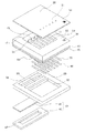
図1は、本発明の実施形態1に係る液体噴射ヘッドの一例であるインクジェット式記録ヘッドの分解斜視図であり、図2は、図1の平面図であり、図3は、図2のA−A′断面図及びB−B′断面図である。図示するように、流路形成基板10は、本実施形態では結晶面方位が(110)面のシリコン単結晶基板からなり、その一方の面には予め熱酸化によって二酸化シリコンからなる厚さ0.5〜2μmの弾性膜50が形成されている。
Hereinafter, the present invention will be described in detail based on embodiments.
(Embodiment 1)
FIG. 1 is an exploded perspective view of an ink jet recording head that is an example of a liquid jet head according to Embodiment 1 of the present invention, FIG. 2 is a plan view of FIG. 1, and FIG. -A 'sectional drawing and BB' sectional drawing. As shown in the drawing, the flow
図1及び図3(a)に示すように、流路形成基板10には、他方面側から異方性エッチングすることにより、複数の隔壁11により区画された複数の圧力発生室12がその幅方向(短手方向)に並設されている。
As shown in FIGS. 1 and 3A, the flow
また、流路形成基板10の圧力発生室12の長手方向一端部側には、インク供給路14と連通路15とが隔壁11によって区画されている。また、連通路15の一端には、後述する保護基板30のリザーバ部31と連通して、各圧力発生室12の共通のインク室(液体室)となるリザーバ100の一部を構成する連通部13が形成されている。すなわち、本実施形態では、流路形成基板10には、圧力発生室12を有する液体流路として、圧力発生室12、連通部13、インク供給路14及び連通路15が設けられている。
In addition, an
インク供給路14は、圧力発生室12の長手方向一端部側に連通し且つ圧力発生室12より小さい断面積を有する。例えば、本実施形態では、インク供給路14は、リザーバ100と各圧力発生室12との間の圧力発生室12側の流路を幅方向に絞ることで、圧力発生室12の幅より小さい幅で形成されている。なお、このように、本実施形態では、流路の幅を片側から絞ることでインク供給路14を形成したが、流路の幅を両側から絞ることでインク供給路を形成してもよい。また、流路の幅を絞るのではなく、厚さ方向から絞ることでインク供給路を形成してもよい。さらに、各連通路15は、圧力発生室12の幅方向両側の隔壁11を連通部13側に延設してインク供給路14と連通部13との間の空間を区画することで形成されている。すなわち、流路形成基板10には、圧力発生室12の幅方向の断面積より小さい断面積を有するインク供給路14と、このインク供給路14に連通すると共にインク供給路14の幅方向の断面積よりも大きい断面積を有する連通路15とが複数の隔壁11により区画されて設けられている。
The
また、流路形成基板10の開口面側には、各圧力発生室12のインク供給路14とは反対側の端部近傍に連通するノズル開口21が穿設されたノズルプレート20が、接着剤や熱溶着フィルム等によって固着されている。なお、ノズルプレート20は、例えば、ガラスセラミックス、シリコン単結晶基板、ステンレス鋼(SUS)等からなる。
Further, on the opening surface side of the flow
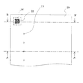
さらに、図1及び図3(b)に示すように、流路形成基板10のノズルプレート20が接合される面側には、圧力発生室12を有する液体流路とは不連続で且つ独立した凹部16が設けられている。
Further, as shown in FIGS. 1 and 3B, the surface of the flow
凹部16は、本実施形態では、圧力発生室12の長手方向外側で、且つ並設された複数の圧力発生室12の並設方向の外側に設けられている。
In the present embodiment, the
本実施形態では、凹部16として、矩形状に開口すると共に、側面を流路形成基板10に開口する面に対して垂直な面で形成した。このような凹部16は、例えば、流路形成基板10を異方性エッチングすることで所望の深さで高精度に形成することができる。
In the present embodiment, the
本実施形態では、凹部16を、一辺が約0.9mmで矩形状に開口するように設けた。また、流路形成基板10の厚さが70μm程度の場合には、凹部16の深さは、例えば、10〜20μmとするのが好ましい。これは、詳しくは後述するが、ノズルプレート20にレーザ加工によってヘッド情報が記録された記録部22を形成した際に、流路形成基板10及びノズルプレート20が加熱され、ノズルプレート20と流路形成基板10との線膨張係数の違いにより変形し、この変形によって流路形成基板10の凹部16による剛性が低下した領域が破壊されるのを確実に防止するためである。すなわち、凹部16を深く形成した場合、レーザ加工によりノズルプレート20と流路形成基板10とが加熱され、加熱による変形によって凹部16の底面側の流路形成基板10の剛性が低い領域に亀裂等の破壊が生じてしまう虞があるからである。
In the present embodiment, the
また、図2に示すように、ノズルプレート20のインクが吐出されるインク滴吐出面側(液体噴射面側)には、凹部16に相対向する領域の当該凹部16の開口面積よりも狭い領域にヘッド情報が記録された記録部22が形成されている。すなわち、凹部16は、記録部22の形成された面積よりも広い開口面積となるように設けられている。
Further, as shown in FIG. 2, a region narrower than the opening area of the
このような記録部22は、例えば、ノズルプレート20のインク滴吐出面側の表面をレーザ加工等により削ることで形成することができる。このとき、レーザ加工は、ノズルプレート20を厚さ方向に貫通することなく行われる。また、例えば、ノズルプレート20のインク滴吐出面側に撥水膜が設けられている場合であっても、レーザ加工により記録部22を形成することができる。
Such a
なお、記録部22としては、例えば、QRコード等の2次元コードや、バーコード等が挙げられる。また、記録部22として、文字や記号等を設けるようにしてもよい。このような記録部22に記録されるヘッド情報は、例えば、ロット番号、インク吐出特性(液体噴射特性)、故障履歴及び修理履歴などの少なくとも1つを含むものである。
Examples of the
また、このような記録部22は、インクジェット式記録ヘッドの外側から、図示しないスキャナによって読み取り可能となっている。
Further, such a
このように、流路形成基板10に液体流路とは不連続で独立した凹部16を設け、ノズルプレート20のインク滴吐出面側の凹部16に相対向する領域の当該凹部16の開口面積よりも狭い領域に記録部22を設けることによって、ヘッド情報を記録部22から容易に読み取ることができる。また、記録部22がインクジェット式記録ヘッドの外周面にあるため、記録部22に記録されるインクジェット式記録ヘッドのヘッド情報が限定されることがない。すなわち、記録部22にインクジェット式記録ヘッドのインク吐出特性の測定や、故障履歴及び修理履歴等のヘッド情報を記録することができる。また、記録部22がインクジェット式記録ヘッドの外周面にあるため、記録部22を追加することもできる。
In this way, the
さらに、ノズルプレート20にヘッド情報を記録部22として直接記録することができるため、例えば、記録ヘッドのロット番号などの識別番号のみを記録部22に記録する場合と異なり、識別番号に関連付けたデータベース等が不要となる。これにより、データベースの一元管理や工場やその他の場所などで、同一のデータベースが用いることができない状況であっても、ヘッド情報の参照を容易に行うことができる。
Further, since the head information can be directly recorded on the
さらに、記録部22を凹部16の開口面積よりも狭い領域にレーザ加工で形成するようにすると共に、凹部16を所定の深さとしたため、レーザ加工により加熱された際に、流路形成基板10とノズルプレート20との線膨張係数の違いによる変形時に凹部16により剛性が低下した領域が破壊されるのを防止することができる。また、凹部16は、圧力発生室12などの流路とは連通していないため、万が一、流路形成基板10とノズルプレート20との線膨張係数の違いによる変形時に凹部16内に異物片が発生しても、その異物が液体流路に流れ出すことがない。
Further, since the
一方、このような流路形成基板10のノズルプレート20とは反対側の面には、上述したように、厚さが例えば約1.0μmの弾性膜50が形成され、この弾性膜50上には、厚さが例えば、約0.4μmの絶縁体膜55が形成されている。さらに、この絶縁体膜55上には、厚さが例えば、約0.2μmの下電極膜60と、厚さが例えば、約1.0μmの圧電体層70と、厚さが例えば、約0.05μmの上電極膜80とが、後述するプロセスで積層形成されて、圧電素子300を構成している。ここで、圧電素子300は、下電極膜60、圧電体層70及び上電極膜80を含む部分をいう。一般的には、圧電素子300の何れか一方の電極を共通電極とし、他方の電極及び圧電体層70を各圧力発生室12毎にパターニングして構成する。そして、ここではパターニングされた何れか一方の電極及び圧電体層70から構成され、両電極への電圧の印加により圧電歪みが生じる部分を圧電体能動部という。本実施形態では、下電極膜60は圧電素子300の共通電極とし、上電極膜80を圧電素子300の個別電極としているが、駆動回路や配線の都合でこれを逆にしても支障はない。何れの場合においても、各圧力発生室12毎に圧電体能動部が形成されていることになる。また、ここでは、圧電素子300と当該圧電素子300の駆動により変位が生じる振動板とを合わせてアクチュエータ装置と称する。すなわち、本実施形態では、圧力発生室12内のインクに圧力変化を生じさせる圧力発生手段として、圧電素子300を有するアクチュエータ装置を設けるようにした。なお、上述した例では、弾性膜50、絶縁体膜55及び下電極膜60が振動板として作用するが、弾性膜50、絶縁体膜55を設けずに、下電極膜60のみを残して下電極膜60を振動板としてもよい。
On the other hand, as described above, the
また、各圧電素子300の上電極膜80には、流路形成基板10のインク供給路14側に延設された金(Au)等のリード電極90がそれぞれ接続されている。このリード電極90を介して各圧電素子300に選択的に電圧が印加される。
Further, a
さらに、圧電素子300が形成された流路形成基板10上には、連通部13に対向する領域にリザーバ部31が設けられた保護基板30が接着剤35を介して接合されている。このリザーバ部31は、上述したように、流路形成基板10の連通部13と連通されて各圧力発生室12の共通のインク室となるリザーバ100を構成している。
Further, on the flow
また、保護基板30には、圧電素子300に対向する領域に、圧電素子300の運動を阻害しない程度の空間を有する圧電素子保持部32が設けられている。なお、圧電素子保持部32は、圧電素子300の運動を阻害しない程度の空間を有していればよく、当該空間は密封されていても、密封されていなくてもよい。
Further, the
さらに、保護基板30の圧電素子保持部32とリザーバ部31との間の領域には、保護基板30を厚さ方向に貫通する貫通孔33が設けられ、この貫通孔33内に下電極膜60の一部及びリード電極90の先端部が露出されている。
Further, a through
また、保護基板30上には、圧電素子300を駆動するための駆動回路200が実装されている。この駆動回路200としては、例えば、回路基板や半導体集積回路(IC)等を用いることができる。そして、駆動回路200とリード電極90とはボンディングワイヤ等の導電性ワイヤからなる接続配線210を介して電気的に接続されている。
A
保護基板30としては、流路形成基板10の熱膨張率と略同一の材料、例えば、ガラス、セラミック材料等を用いることが好ましく、本実施形態では、流路形成基板10と同一材料の面方位(110)のシリコン単結晶基板を用いて形成した。
As the
また、保護基板30上には、封止膜41及び固定板42とからなるコンプライアンス基板40が接合されている。ここで、封止膜41は、剛性が低く可撓性を有する材料(例えば、厚さが6μmのポリフェニレンサルファイド(PPS)フィルム)からなり、この封止膜41によってリザーバ部31の一方面が封止されている。また、固定板42は、金属等の硬質の材料(例えば、厚さが30μmのステンレス鋼(SUS)等)で形成される。この固定板42のリザーバ100に対向する領域は、厚さ方向に完全に除去された開口部43となっているため、リザーバ100の一方面は可撓性を有する封止膜41のみで封止されている。
A
このような本実施形態のインクジェット式記録ヘッドでは、図示しない外部インク供給手段からインクを取り込み、リザーバ100からノズル開口21に至るまで内部をインクで満たした後、駆動回路200からの記録信号に従い、圧力発生室12に対応するそれぞれの下電極膜60と上電極膜80との間に電圧を印加し、弾性膜50、絶縁体膜55、下電極膜60及び圧電体層70をたわみ変形させることにより、各圧力発生室12内の圧力が高まりノズル開口21からインク滴が吐出する。
In such an ink jet recording head of this embodiment, ink is taken in from an external ink supply unit (not shown), filled with ink from the
以下、このようなインクジェット式記録ヘッドの製造方法について、図4〜図8を参照して説明する。なお、図4〜図6は、液体噴射ヘッドの一例であるインクジェット式記録ヘッドの製造方法を示す図2のA−A′断面図であり、図7及び図8は、図2のB−B′断面図である。 Hereinafter, a method for manufacturing such an ink jet recording head will be described with reference to FIGS. 4 to 6 are cross-sectional views taken along the line AA ′ of FIG. 2 showing a method of manufacturing an ink jet recording head which is an example of a liquid ejecting head, and FIGS. 7 and 8 are BB of FIG. It is a cross-sectional view.
まず、図4(a)に示すように、シリコン単結晶基板からなるシリコンウェハである流路形成基板用ウェハ110を約1100℃の拡散炉で熱酸化し、その表面に弾性膜50を構成する二酸化シリコン膜51を形成する。なお、本実施形態では、流路形成基板用ウェハ110として、結晶面方位が(110)面の厚さが約625μmと比較的厚く剛性の高いシリコンウェハを用いている。
First, as shown in FIG. 4A, a flow path forming
次に、図4(b)に示すように、弾性膜50(二酸化シリコン膜51)上に、酸化ジルコニウムからなる絶縁体膜55を形成する。具体的には、弾性膜50(二酸化シリコン膜51)上に、例えば、スパッタ法等によりジルコニウム(Zr)層を形成後、このジルコニウム層を、例えば、500〜1200℃の拡散炉で熱酸化することにより酸化ジルコニウム(ZrO2)からなる絶縁体膜55を形成する。
Next, as shown in FIG. 4B, an
次いで、図4(c)に示すように、例えば、白金(Pt)とイリジウム(Ir)とを絶縁体膜55上に積層することにより下電極膜60を形成した後、この下電極膜60を所定形状にパターニングする。次に、図5(a)に示すように、例えば、チタン酸ジルコン酸鉛(PZT)等からなる圧電体層70と、例えば、イリジウムからなる上電極膜80とを流路形成基板用ウェハ110の全面に形成し、図5(b)に示すように、これら圧電体層70及び上電極膜80を、各圧力発生室12に対向する領域にパターニングして圧電素子300を形成する。
Next, as shown in FIG. 4C, for example, after the
なお、圧電素子300を構成する圧電体層70の材料としては、例えば、チタン酸ジルコン酸鉛(PZT)等の強誘電性圧電性材料や、これにニオブ、ニッケル、マグネシウム、ビスマス又はイットリウム等の金属を添加したリラクサ強誘電体等が用いられる。その組成は、圧電素子300の特性、用途等を考慮して適宜選択すればよい。また、圧電体層70の形成方法は、特に限定されないが、例えば、本実施形態では、金属有機物を触媒に溶解・分散したいわゆるゾルを塗布乾燥してゲル化し、さらに高温で焼成することで金属酸化物からなる圧電体層70を得る、いわゆるゾル−ゲル法を用いて圧電体層70を形成した。なお、圧電体層70を形成する方法としては、ゾル−ゲル法に限定されず、例えば、MOD法やスパッタ法等を用いてもよい。
The material of the
次に、図5(c)に示すように、流路形成基板用ウェハ110の全面に亘って金(Au)からなるリード電極90を形成後、各圧電素子300毎にパターニングする。
Next, as shown in FIG. 5C, a
次に、図5(d)に示すように、保護基板用ウェハ130を、流路形成基板用ウェハ110上に接着剤35を介して接着する。ここで、この保護基板用ウェハ130には、リザーバ部31及び圧電素子保持部32が予め形成されている。なお、この保護基板用ウェハ130は、例えば、400μm程度の厚さを有するため、保護基板用ウェハ130を接合することによって流路形成基板用ウェハ110の剛性は著しく向上することになる。
Next, as shown in FIG. 5D, the
次いで、図6(a)に示すように、流路形成基板用ウェハ110をある程度の厚さとなるまで研磨した後、さらにフッ硝酸によってウェットエッチングすることにより流路形成基板用ウェハ110を所定の厚みにする。例えば、本実施形態では、研磨及びウェットエッチングによって、流路形成基板用ウェハ110を、約70μmの厚さとなるように加工した。
Next, as shown in FIG. 6A, after the flow path forming
次に、図6(b)に示すように、流路形成基板用ウェハ110上に、例えば、窒化シリコン(SiN)からなるマスク膜52を新たに形成し、所定形状にパターニングする。詳しくは、マスク膜52をパターニングすることにより、圧力発生室12、連通部13、インク供給路14及び連通路15が形成される領域に開口する第1の開口部52aを形成する。
Next, as shown in FIG. 6B, a
次に、図6(c)に示すように、流路形成基板用ウェハ110をマスク膜52を介して水酸化カリウム(KOH)水溶液等のアルカリ溶液を用いた異方性エッチング(ウェットエッチング)することにより、圧力発生室12、連通部13、インク供給路14及び連通路15の深さ方向(流路形成基板用ウェハ110の厚さ方向)の一部を形成する。すなわち、本実施形態では、流路形成基板用ウェハ110をマスク膜52を介してハーフエッチングすることにより、流路形成基板用ウェハ110の第1の開口部52aにより露出された領域を徐々に除去し、圧力発生室12、連通部13、インク供給路14及び連通路15の深さ方向の開口側を形成する。なお、ハーフエッチングでは、エッチング時間を調整することにより行うことができる。
Next, as shown in FIG. 6C, anisotropic etching (wet etching) is performed on the flow path forming
次に、図7(a)に示すように、流路形成基板用ウェハ110のマスク膜52の凹部16が形成される領域に第2の開口部52bを形成する。本実施形態では、第2の開口部52bは、例えば、レーザ加工により形成することができる。
Next, as shown in FIG. 7A, a
次に、図7(b)に示すように、流路形成基板用ウェハ110をマスク膜52を介して異方性エッチングすることにより、圧力発生室12、連通部13、インク供給路14及び連通路15を形成すると共に、凹部16を形成する。すなわち、流路形成基板用ウェハ110をアルカリ溶液に浸漬すると、第1の開口部52aによって露出された領域は、弾性膜50に達するまで異方性エッチングされて、流路形成基板用ウェハ110の厚さ方向に貫通した圧力発生室12、連通部13、インク供給路14及び連通路15が形成される。また、同時に、流路形成基板用ウェハ110の第2の開口部52bによって露出された領域も除去されて所定の深さの凹部16が形成される。すなわち、この異方性エッチングでは、第1の開口部52aにより露出された領域が弾性膜50に達するまでの時間しか行われないため、第2の開口部52bに対向する領域は、弾性膜50に達する前に異方性エッチングが終了される。このため、凹部16は、弾性膜50に達することなく、凹形状で所定の深さで形成することができる。
Next, as shown in FIG. 7B, the
なお、このように、圧力発生室12等の液体流路の弾性膜50側の形成と、凹部16の形成とを異方性エッチングにより同時に行う場合には、上述した図6(c)に示す工程で、流路形成基板用ウェハ110の液体流路の底面側の残りの厚さが、凹部16が形成される深さと同等か、もしくは、凹部16の深さよりも薄くなるように形成する必要がある。これにより、図7(b)に示す工程で、圧力発生室12等の液体流路の弾性膜50側の形成と同時に所望の深さで凹部16を形成することができる。このように、凹部16と圧力発生室12等を有する液体流路とを同時に形成することで、製造工程を簡略化してコストを低減することができる。
In the case where the formation of the liquid flow path such as the
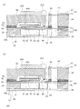
その後は、図8(a)に示すように、流路形成基板用ウェハ110の圧力発生室12が開口する面側のマスク膜52を除去し、流路形成基板用ウェハ110及び保護基板用ウェハ130の外周縁部の不要部分を、例えば、ダイシング等により切断することによって除去する。そして、流路形成基板用ウェハ110の保護基板用ウェハ130とは反対側の面にノズル開口21が穿設されたノズルプレート20を接合すると共に、保護基板用ウェハ130にコンプライアンス基板40を接合し、これら流路形成基板用ウェハ110等を、図1に示すような一つのチップサイズの流路形成基板10等に分割することによって上述した構造のインクジェット式記録ヘッドが製造される。
Thereafter, as shown in FIG. 8A, the
そして、このようにインクジェット式記録ヘッドが製造された後は、図8(b)に示すように、ノズルプレート20のインク滴吐出面側の凹部16に相対向する領域の凹部16の開口よりも狭い領域にヘッド情報が記録された記録部22をレーザ光を出力するレーザ加工装置400を用いたレーザ加工により形成する。すなわち、ノズルプレート20のインク滴吐出面側をレーザ加工により削ることで、QRコード等の二次元コードやバーコード等のヘッド情報が記録された記録部22を形成する。
After the ink jet recording head is manufactured in this way, as shown in FIG. 8B, the opening of the
この記録部22を形成するタイミングは、インクジェット式記録ヘッドを製造した後であれば、特に限定されず、例えば、インクジェット式記録ヘッドのインク吐出特性を測定した後、このインク吐出特性からなるヘッド情報を記録部22として形成するようにしてもよい。また、インクジェット式記録ヘッドを使用した後で故障した場合などに、故障情報からなるヘッド情報を記録部22として形成するようにしてもよい。さらに、故障を修理した場合などに修理情報からなるヘッド情報を記録部22として形成するようにしてもよい。
The timing for forming the
さらに、記録部22に記録するヘッド情報としては、例えば、流路形成基板用ウェハ110のロット番号や、ウェハ内での位置情報などが挙げられる。すなわち、記録部22のヘッド情報を読み取ることで、インクジェット式記録ヘッドが同一ウェハから製造されたものかを識別することができると共に、ウェハ内の位置によるインク吐出特性のばらつきなども記録部22から判別することができる。
Furthermore, examples of the head information recorded in the
なお、上述したマスク膜52に第2の開口部52bを形成する際に、この記録部22を形成する際に使用するレーザ加工装置400を用いることで、製造コストを低減することができる。
In addition, when forming the
このように、流路形成基板用ウェハ110(流路形成基板10)に凹部16を形成した後、ノズルプレート20のインク滴吐出面側に凹部16の開口面積よりも狭い領域に記録部22をレーザ加工により形成することで、ノズルプレート20の流路形成基板10との接合面側が、レーザ加工により凸形状に突出したとしても、凹部16によって、突出した領域が流路形成基板10に直接当接することがなく、流路形成基板10のクラック等の破壊を防止することができる。
As described above, after the
また、凹部16を所定の深さとすることで、記録部22を形成する際のレーザ加工による加熱によって、流路形成基板10とノズルプレート20との線膨張係数の違いにより両者が変形したとしても、凹部16によって剛性が低下した領域の流路形成基板10の破壊を防止することができる。
Further, by setting the
(他の実施形態)
以上、本発明の実施形態1について説明したが、本発明の基本的構成は、上述したものに限定されるものではない。例えば、上述した実施形態1では、流路形成基板10に1つの凹部16を設け、ノズルプレート20に1つの記録部22を設けるようにしたが、特にこれに限定されず、例えば、1つの凹部16に対して複数の記録部22を設けるようにしてもよい。また、複数の凹部を設け、各凹部に対して1つ以上の記録部を設けるようにしてもよい。さらに、予め複数の凹部を設けておき、インク吐出特性の測定後、故障後、修理後などにノズルプレート20に適宜ヘッド情報が記録された記録部を設けるようにしてもよい。
(Other embodiments)
As mentioned above, although Embodiment 1 of this invention was demonstrated, the basic composition of this invention is not limited to what was mentioned above. For example, in the first embodiment described above, one
また、本発明の実施形態1では、狭い領域に精度の高い加工ができることから、記録部22の加工にレーザを用いて説明したが、記録部22の形成方法は、レーザ加工に限定されず、記録部22を形成する際の加工による加熱によって、流路形成基板10とノズルプレート20との線膨張係数の違いにより両者が変形してしまう加熱加工であれば本発明を適用することができる。
Further, in Embodiment 1 of the present invention, since processing with high accuracy can be performed in a narrow area, the laser is used for processing of the
さらに、上述した実施形態1では、凹部16として、矩形状に開口する凹形状のものを例示したが、凹部16の形状は特にこれに限定されるものではなく、例えば、菱形状、円形状、楕円形状等に開口するものであってもよく、また、開口面積と底面積とが異なるように側面を傾斜させるようにしてもよい。
Furthermore, in Embodiment 1 mentioned above, although the concave-shaped thing opened rectangularly was illustrated as the recessed
また、上述した実施形態1では、流路形成基板10として、結晶面方位が(110)面のシリコン単結晶基板を例示したが、特にこれに限定されず、例えば、結晶面方位が(100)面のシリコン単結晶基板を用いるようにしてもよく、また、SOI基板、ガラス等の材料を用いるようにしてもよい。何れの材料の流路形成基板10を用いた場合であっても、凹部16は、流路形成基板10を異方性エッチングすることにより所望の深さで高精度に形成することができる。勿論、凹部16は、ドライエッチング等により形成するようにしてもよい。
In the first embodiment described above, a silicon single crystal substrate having a (110) crystal plane orientation is illustrated as the flow
また、実施形態1のインクジェット式記録ヘッドは、インクカートリッジ等と連通するインク流路を具備する記録ヘッドユニットの一部を構成して、インクジェット式記録装置に搭載される。図9は、そのインクジェット式記録装置の一例を示す概略図である。 The ink jet recording head according to the first embodiment constitutes a part of a recording head unit including an ink flow path communicating with an ink cartridge and the like, and is mounted on the ink jet recording apparatus. FIG. 9 is a schematic view showing an example of the ink jet recording apparatus.
図9に示すように、インクジェット式記録ヘッドを有する記録ヘッドユニット1A及び1Bは、インク供給手段を構成するカートリッジ2A及び2Bが着脱可能に設けられ、この記録ヘッドユニット1A及び1Bを搭載したキャリッジ3は、装置本体4に取り付けられたキャリッジ軸5に軸方向移動自在に設けられている。この記録ヘッドユニット1A及び1Bは、例えば、それぞれブラックインク組成物及びカラーインク組成物を吐出するものとしている。
As shown in FIG. 9, in the
そして、駆動モータ6の駆動力が図示しない複数の歯車およびタイミングベルト7を介してキャリッジ3に伝達されることで、記録ヘッドユニット1A及び1Bを搭載したキャリッジ3はキャリッジ軸5に沿って移動される。一方、装置本体4にはキャリッジ軸5に沿ってプラテン8が設けられており、図示しない給紙ローラなどにより給紙された紙等の記録媒体である記録シートSがプラテン8に巻き掛けられて搬送されるようになっている。
The driving force of the driving
上述した実施形態においては、圧力発生素子とし圧電素子を用いて説明したが、振動板と電極を所定の隙間を開けて配置し、静電気力で振動板の振動を制御する、いわゆる静電アクチュエータを圧力発生素子として用いても良い。また、液体噴射ヘッドの一例としてインクジェット式記録ヘッドを挙げて説明したが、本発明は、広く液体噴射ヘッド全般を対象としたものであり、インク以外の液体を噴射する液体噴射ヘッドの製造方法にも勿論適用することができる。その他の液体噴射ヘッドとしては、例えば、プリンタ等の画像記録装置に用いられる各種の記録ヘッド、液晶ディスプレー等のカラーフィルタの製造に用いられる色材噴射ヘッド、有機ELディスプレー、FED(電界放出ディスプレー)等の電極形成に用いられる電極材料噴射ヘッド、バイオchip製造に用いられる生体有機物噴射ヘッド等が挙げられる。 In the above-described embodiment, the piezoelectric element is used as the pressure generating element. However, a so-called electrostatic actuator that controls the vibration of the diaphragm with electrostatic force by arranging the diaphragm and the electrode with a predetermined gap is provided. It may be used as a pressure generating element. In addition, although an ink jet recording head has been described as an example of a liquid ejecting head, the present invention is intended for a wide range of liquid ejecting heads in general, and a method for manufacturing a liquid ejecting head that ejects liquid other than ink. Of course, it can also be applied. Other liquid ejecting heads include, for example, various recording heads used in image recording apparatuses such as printers, color material ejecting heads used in the manufacture of color filters such as liquid crystal displays, organic EL displays, and FEDs (field emission displays). Examples thereof include an electrode material ejection head used for electrode formation, a bioorganic matter ejection head used for biochip production, and the like.
10 流路形成基板、 12 圧力発生室、 13 連通部、 14 インク供給路、 15 連通部、 16 凹部、 20 ノズルプレート、 21 ノズル開口、 22 記録部、 30 保護基板、 31 リザーバ部、 32 圧電素子保持部、 40 コンプライアンス基板、 50 弾性膜、 55 絶縁体膜、 60 下電極膜、 70 圧電体層、 80 上電極膜、 90 リード電極、 100 リザーバ、 110 流路形成基板用ウェハ、 200 駆動回路、 210 駆動配線、 130 保護基板用ウェハ、 300 圧電素子、400 レーザ加工装置
DESCRIPTION OF
Claims (11)
前記流路形成基板の前記一方面側に前記ノズルプレートを接合する工程と、
前記ノズルプレートに垂直な位置から見た際に、前記ノズルプレートの前記液体が噴射される液体噴射面側の前記凹部に相対向する領域に包含され、且つ当該凹部の開口面積よりも狭い領域にヘッド情報が記録された記録部を形成する工程と、を具備することを特徴とする液体噴射ヘッドの製造方法。 A liquid flow path having a pressure generation chamber communicating with a nozzle opening for ejecting liquid and a pressure generation means for causing a pressure change in the liquid in the pressure generation chamber are formed on the flow path forming substrate, and the flow path formation Forming a recess that is discontinuous and independent of the liquid flow path on one surface side to which the nozzle plate provided with the nozzle openings of the substrate is joined;
Bonding the nozzle plate to the one surface side of the flow path forming substrate;
When viewed from a position perpendicular to the nozzle plate, the nozzle plate is included in a region facing the concave portion on the liquid ejection surface side on which the liquid is ejected and is narrower than the opening area of the concave portion. And a step of forming a recording portion on which head information is recorded.
前記流路形成基板の前記ノズルプレートが接合される一方面側に、前記液体流路とは不連続で独立した凹部が設けられていると共に、前記ノズルプレートに垂直な位置から見た際に、前記ノズルプレートの前記液体が噴射される液体噴射面側の前記凹部に相対向する領域に包含され、且つ当該凹部の開口面積よりも狭い領域にヘッド情報が記録された記録部が設けられていることを特徴とする液体噴射ヘッド。 A flow path forming substrate having a pressure flow generation chamber having a pressure generation chamber communicating with a nozzle opening for injecting liquid and having a pressure generation means for causing a pressure change in the liquid in the pressure generation chamber; A nozzle plate bonded to one side of the substrate and provided with the nozzle openings,
On one side of the flow path forming substrate to which the nozzle plate is joined, a recess that is discontinuous and independent from the liquid flow path is provided, and when viewed from a position perpendicular to the nozzle plate, A recording unit in which head information is recorded in a region that is included in a region opposite to the concave portion on the liquid ejection surface side on which the liquid is ejected of the nozzle plate and that is smaller than the opening area of the concave portion is provided. A liquid jet head characterized by that.
Priority Applications (1)
| Application Number | Priority Date | Filing Date | Title |
|---|---|---|---|
| JP2006193350A JP4831325B2 (en) | 2006-07-13 | 2006-07-13 | Liquid ejecting head manufacturing method, liquid ejecting head, and liquid ejecting apparatus |
Applications Claiming Priority (1)
| Application Number | Priority Date | Filing Date | Title |
|---|---|---|---|
| JP2006193350A JP4831325B2 (en) | 2006-07-13 | 2006-07-13 | Liquid ejecting head manufacturing method, liquid ejecting head, and liquid ejecting apparatus |
Publications (3)
| Publication Number | Publication Date |
|---|---|
| JP2008018642A JP2008018642A (en) | 2008-01-31 |
| JP2008018642A5 JP2008018642A5 (en) | 2009-07-23 |
| JP4831325B2 true JP4831325B2 (en) | 2011-12-07 |
Family
ID=39074981
Family Applications (1)
| Application Number | Title | Priority Date | Filing Date |
|---|---|---|---|
| JP2006193350A Expired - Fee Related JP4831325B2 (en) | 2006-07-13 | 2006-07-13 | Liquid ejecting head manufacturing method, liquid ejecting head, and liquid ejecting apparatus |
Country Status (1)
| Country | Link |
|---|---|
| JP (1) | JP4831325B2 (en) |
Families Citing this family (2)
| Publication number | Priority date | Publication date | Assignee | Title |
|---|---|---|---|---|
| JP2012071552A (en) * | 2010-09-29 | 2012-04-12 | Seiko Epson Corp | Method of manufacturing liquid injection head, and method of manufacturing liquid injection device |
| JP6767666B2 (en) | 2016-01-29 | 2020-10-14 | セイコーエプソン株式会社 | Manufacturing method of liquid injection head, liquid injection device and liquid injection device |
Family Cites Families (4)
| Publication number | Priority date | Publication date | Assignee | Title |
|---|---|---|---|---|
| JP2004230787A (en) * | 2003-01-31 | 2004-08-19 | Canon Inc | Inkjet recording head with individual information |
| JP4235820B2 (en) * | 2004-05-07 | 2009-03-11 | ブラザー工業株式会社 | Ink jet recording head, head unit, and method of manufacturing ink jet recording head |
| JP4661126B2 (en) * | 2004-08-10 | 2011-03-30 | 富士ゼロックス株式会社 | Ink jet recording head and method of manufacturing ink jet recording head |
| JP4543850B2 (en) * | 2004-09-22 | 2010-09-15 | ブラザー工業株式会社 | Inkjet printer head manufacturing method |
-
2006
- 2006-07-13 JP JP2006193350A patent/JP4831325B2/en not_active Expired - Fee Related
Also Published As
| Publication number | Publication date |
|---|---|
| JP2008018642A (en) | 2008-01-31 |
Similar Documents
| Publication | Publication Date | Title |
|---|---|---|
| JP4321552B2 (en) | Actuator device and liquid jet head | |
| JP4258668B2 (en) | Liquid ejecting head and liquid ejecting apparatus | |
| JP4645831B2 (en) | Liquid ejecting head, manufacturing method thereof, and liquid ejecting apparatus | |
| JP2007194373A (en) | Manufacturing method of silicon device and manufacturing method of liquid injection head | |
| JP4553129B2 (en) | Liquid ejecting head and liquid ejecting apparatus | |
| JP2009214522A (en) | Liquid jet head, method of manufacturing liquid jet head, and liquid jet device | |
| JP4182360B2 (en) | Liquid ejecting head and liquid ejecting apparatus | |
| JP4831325B2 (en) | Liquid ejecting head manufacturing method, liquid ejecting head, and liquid ejecting apparatus | |
| JP2009029011A (en) | Liquid jetting head and liquid jetting device | |
| JP2009018551A (en) | Actuator, liquid jet head and liquid jet apparatus | |
| JP2010120270A (en) | Liquid injection head, liquid injection device, actuator device, and method of manufacturing the liquid injection head | |
| JP2009029012A (en) | Liquid jetting head and liquid jet apparatus | |
| JP4363458B2 (en) | Liquid ejecting head unit and liquid ejecting apparatus | |
| JP4623287B2 (en) | Liquid ejecting head, manufacturing method thereof, and liquid ejecting apparatus | |
| JP2010228272A (en) | Method for manufacturing liquid jetting head, liquid jetting head, and liquid jetting device | |
| JP5447786B2 (en) | Liquid ejecting head, liquid ejecting apparatus, and actuator device | |
| JP2004284176A (en) | Manufacturing method for liquid injection head | |
| JP2010173197A (en) | Liquid discharge head, liquid discharge device, actuator device, and manufacturing method of liquid discharge head | |
| JP2006281603A (en) | Bonding method, manufacturing method of liquid jetting head, bonded substrate, liquid jetting head, and liquid jetting device | |
| JP4492059B2 (en) | Liquid ejecting head and liquid ejecting apparatus | |
| JP4475042B2 (en) | Method for manufacturing liquid jet head | |
| JP2009061729A (en) | Liquid injection head and liquid injection apparatus | |
| JP5690476B2 (en) | Liquid ejecting head manufacturing method, liquid ejecting head, and liquid ejecting apparatus | |
| JP2005053081A (en) | Liquid ejecting head and liquid ejector | |
| JP2009029019A (en) | Liquid jetting head and liquid jetting device |
Legal Events
| Date | Code | Title | Description |
|---|---|---|---|
| A521 | Written amendment |
Free format text: JAPANESE INTERMEDIATE CODE: A523 Effective date: 20090609 |
|
| A621 | Written request for application examination |
Free format text: JAPANESE INTERMEDIATE CODE: A621 Effective date: 20090609 |
|
| A977 | Report on retrieval |
Free format text: JAPANESE INTERMEDIATE CODE: A971007 Effective date: 20110606 |
|
| A131 | Notification of reasons for refusal |
Free format text: JAPANESE INTERMEDIATE CODE: A131 Effective date: 20110608 |
|
| A521 | Written amendment |
Free format text: JAPANESE INTERMEDIATE CODE: A523 Effective date: 20110802 |
|
| TRDD | Decision of grant or rejection written | ||
| A01 | Written decision to grant a patent or to grant a registration (utility model) |
Free format text: JAPANESE INTERMEDIATE CODE: A01 Effective date: 20110824 |
|
| A01 | Written decision to grant a patent or to grant a registration (utility model) |
Free format text: JAPANESE INTERMEDIATE CODE: A01 |
|
| A61 | First payment of annual fees (during grant procedure) |
Free format text: JAPANESE INTERMEDIATE CODE: A61 Effective date: 20110906 |
|
| R150 | Certificate of patent or registration of utility model |
Free format text: JAPANESE INTERMEDIATE CODE: R150 |
|
| FPAY | Renewal fee payment (event date is renewal date of database) |
Free format text: PAYMENT UNTIL: 20140930 Year of fee payment: 3 |
|
| LAPS | Cancellation because of no payment of annual fees |