JP4827615B2 - Information processing apparatus, printing system, monitoring method, program, and storage medium - Google Patents
Information processing apparatus, printing system, monitoring method, program, and storage medium Download PDFInfo
- Publication number
- JP4827615B2 JP4827615B2 JP2006148242A JP2006148242A JP4827615B2 JP 4827615 B2 JP4827615 B2 JP 4827615B2 JP 2006148242 A JP2006148242 A JP 2006148242A JP 2006148242 A JP2006148242 A JP 2006148242A JP 4827615 B2 JP4827615 B2 JP 4827615B2
- Authority
- JP
- Japan
- Prior art keywords
- monitoring
- job
- printing device
- information processing
- Prior art date
- Legal status (The legal status is an assumption and is not a legal conclusion. Google has not performed a legal analysis and makes no representation as to the accuracy of the status listed.)
- Expired - Fee Related
Links
Images


Classifications
-
- G—PHYSICS
- G06—COMPUTING; CALCULATING OR COUNTING
- G06F—ELECTRIC DIGITAL DATA PROCESSING
- G06F3/00—Input arrangements for transferring data to be processed into a form capable of being handled by the computer; Output arrangements for transferring data from processing unit to output unit, e.g. interface arrangements
- G06F3/12—Digital output to print unit, e.g. line printer, chain printer
- G06F3/1201—Dedicated interfaces to print systems
- G06F3/1223—Dedicated interfaces to print systems specifically adapted to use a particular technique
- G06F3/1237—Print job management
- G06F3/126—Job scheduling, e.g. queuing, determine appropriate device
-
- G—PHYSICS
- G06—COMPUTING; CALCULATING OR COUNTING
- G06F—ELECTRIC DIGITAL DATA PROCESSING
- G06F3/00—Input arrangements for transferring data to be processed into a form capable of being handled by the computer; Output arrangements for transferring data from processing unit to output unit, e.g. interface arrangements
- G06F3/12—Digital output to print unit, e.g. line printer, chain printer
- G06F3/1201—Dedicated interfaces to print systems
- G06F3/1202—Dedicated interfaces to print systems specifically adapted to achieve a particular effect
- G06F3/1203—Improving or facilitating administration, e.g. print management
- G06F3/1207—Improving or facilitating administration, e.g. print management resulting in the user being informed about print result after a job submission
-
- G—PHYSICS
- G06—COMPUTING; CALCULATING OR COUNTING
- G06F—ELECTRIC DIGITAL DATA PROCESSING
- G06F3/00—Input arrangements for transferring data to be processed into a form capable of being handled by the computer; Output arrangements for transferring data from processing unit to output unit, e.g. interface arrangements
- G06F3/12—Digital output to print unit, e.g. line printer, chain printer
- G06F3/1201—Dedicated interfaces to print systems
- G06F3/1202—Dedicated interfaces to print systems specifically adapted to achieve a particular effect
- G06F3/1218—Reducing or saving of used resources, e.g. avoiding waste of consumables or improving usage of hardware resources
- G06F3/122—Reducing or saving of used resources, e.g. avoiding waste of consumables or improving usage of hardware resources with regard to computing resources, e.g. memory, CPU
-
- G—PHYSICS
- G06—COMPUTING; CALCULATING OR COUNTING
- G06F—ELECTRIC DIGITAL DATA PROCESSING
- G06F3/00—Input arrangements for transferring data to be processed into a form capable of being handled by the computer; Output arrangements for transferring data from processing unit to output unit, e.g. interface arrangements
- G06F3/12—Digital output to print unit, e.g. line printer, chain printer
- G06F3/1201—Dedicated interfaces to print systems
- G06F3/1223—Dedicated interfaces to print systems specifically adapted to use a particular technique
- G06F3/1237—Print job management
- G06F3/1259—Print job monitoring, e.g. job status
-
- G—PHYSICS
- G06—COMPUTING; CALCULATING OR COUNTING
- G06F—ELECTRIC DIGITAL DATA PROCESSING
- G06F3/00—Input arrangements for transferring data to be processed into a form capable of being handled by the computer; Output arrangements for transferring data from processing unit to output unit, e.g. interface arrangements
- G06F3/12—Digital output to print unit, e.g. line printer, chain printer
- G06F3/1201—Dedicated interfaces to print systems
- G06F3/1278—Dedicated interfaces to print systems specifically adapted to adopt a particular infrastructure
- G06F3/1285—Remote printer device, e.g. being remote from client or server
- G06F3/1288—Remote printer device, e.g. being remote from client or server in client-server-printer device configuration
-
- H—ELECTRICITY
- H04—ELECTRIC COMMUNICATION TECHNIQUE
- H04N—PICTORIAL COMMUNICATION, e.g. TELEVISION
- H04N1/00—Scanning, transmission or reproduction of documents or the like, e.g. facsimile transmission; Details thereof
- H04N1/00912—Arrangements for controlling a still picture apparatus or components thereof not otherwise provided for
- H04N1/00915—Assigning priority to, or interrupting, a particular operation
-
- H—ELECTRICITY
- H04—ELECTRIC COMMUNICATION TECHNIQUE
- H04N—PICTORIAL COMMUNICATION, e.g. TELEVISION
- H04N1/00—Scanning, transmission or reproduction of documents or the like, e.g. facsimile transmission; Details thereof
- H04N1/00912—Arrangements for controlling a still picture apparatus or components thereof not otherwise provided for
- H04N1/00954—Scheduling operations or managing resources
-
- H—ELECTRICITY
- H04—ELECTRIC COMMUNICATION TECHNIQUE
- H04N—PICTORIAL COMMUNICATION, e.g. TELEVISION
- H04N1/00—Scanning, transmission or reproduction of documents or the like, e.g. facsimile transmission; Details thereof
- H04N1/32—Circuits or arrangements for control or supervision between transmitter and receiver or between image input and image output device, e.g. between a still-image camera and its memory or between a still-image camera and a printer device
- H04N1/32502—Circuits or arrangements for control or supervision between transmitter and receiver or between image input and image output device, e.g. between a still-image camera and its memory or between a still-image camera and a printer device in systems having a plurality of input or output devices
- H04N1/32523—Circuits or arrangements for control or supervision between transmitter and receiver or between image input and image output device, e.g. between a still-image camera and its memory or between a still-image camera and a printer device in systems having a plurality of input or output devices a plurality of output devices
- H04N1/32539—Detecting or indicating the status of the output devices
-
- H—ELECTRICITY
- H04—ELECTRIC COMMUNICATION TECHNIQUE
- H04N—PICTORIAL COMMUNICATION, e.g. TELEVISION
- H04N1/00—Scanning, transmission or reproduction of documents or the like, e.g. facsimile transmission; Details thereof
- H04N1/32—Circuits or arrangements for control or supervision between transmitter and receiver or between image input and image output device, e.g. between a still-image camera and its memory or between a still-image camera and a printer device
- H04N1/32609—Fault detection or counter-measures, e.g. original mis-positioned, shortage of paper
- H04N1/32625—Fault detection
- H04N1/32635—Fault detection of reproducing apparatus or receiver, e.g. out of paper
-
- H—ELECTRICITY
- H04—ELECTRIC COMMUNICATION TECHNIQUE
- H04N—PICTORIAL COMMUNICATION, e.g. TELEVISION
- H04N1/00—Scanning, transmission or reproduction of documents or the like, e.g. facsimile transmission; Details thereof
- H04N1/32—Circuits or arrangements for control or supervision between transmitter and receiver or between image input and image output device, e.g. between a still-image camera and its memory or between a still-image camera and a printer device
- H04N1/32609—Fault detection or counter-measures, e.g. original mis-positioned, shortage of paper
- H04N1/32646—Counter-measures
Landscapes
- Engineering & Computer Science (AREA)
- Theoretical Computer Science (AREA)
- Multimedia (AREA)
- Signal Processing (AREA)
- Physics & Mathematics (AREA)
- General Engineering & Computer Science (AREA)
- Human Computer Interaction (AREA)
- General Physics & Mathematics (AREA)
- Mathematical Physics (AREA)
- Accessory Devices And Overall Control Thereof (AREA)
Description
本発明は、コンピュータの負荷を軽減し効率的に印刷ジョブ又は印刷デバイスを管理する為の仕組みに関する。 The present invention relates to a mechanism for reducing the load on a computer and efficiently managing print jobs or printing devices.
ネットワーク上に印刷ジョブを分散し、複数のプリンタを用いて高速印刷を実現する分散印刷技術が特許文献1等により知られている。この特許文献1によれば、複数に分散された印刷ジョブの状態をパーソナルコンピュータ等のジョブ発行元で収集し、各印刷ジョブの状態をパーソナルコンピュータで平行して管理することが開示されている。
しかし、例えば、ネットワークで接続された全国各拠点に存在する大量の印刷デバイスに大量の印刷ジョブを投入し印刷を行うケースがある。数台の印刷デバイスならまだしも、例えば数百台の印刷デバイスの監視を行おうとすると、特許文献1に開示される監視方法では現実的ではない。数百台の印刷デバイスを平行して監視するのは処理負荷が非常に大きくなる。又は、著しく監視を行うコンピュータのコストを上昇させてしまう。 However, there are cases where, for example, a large number of print jobs are input to a large number of printing devices that exist at various locations nationwide connected via a network to perform printing. Even if several printing devices are used, for example, if it is attempted to monitor several hundred printing devices, the monitoring method disclosed in Patent Document 1 is not practical. Monitoring hundreds of printing devices in parallel increases the processing load. Or, the cost of a computer that performs monitoring significantly increases.
本発明は上記問題点に鑑みてなされたものであり、複数の印刷デバイスと通信可能な情報処理装置であって、前記印刷デバイスに転送すべき印刷ジョブが生成された場合に、印刷ジョブの出力先の印刷デバイスを監視対象キューに順次登録する登録手段と、前記印刷デバイスの監視のための接続数が最大接続数に達していない場合、前記登録手段による前記監視対象キューへの印刷デバイスの登録順序に従い印刷デバイスの監視を開始する監視手段と、前記印刷デバイスに連続で転送された印刷ジョブの数を示す連続転送数、及び、前記印刷デバイスを連続で監視している時間を示す連続監視時間に関する特定の条件が成立したか否かを判定する判定手段と、前記判定手段の判定に基づき印刷デバイスの監視を一旦中断する監視中断手段と、を有し、前記登録手段は、監視中断した印刷デバイスに登録されている印刷ジョブの中で完了していない印刷ジョブがある場合に、前記監視中断した印刷デバイスを前記監視対象キューに再登録することを特徴とする。 The present invention has been made in view of the above problems, and is an information processing apparatus capable of communicating with a plurality of printing devices. When a print job to be transferred to the printing device is generated, the print job is output. If a registration unit ahead of the printing device are sequentially registered in the monitoring queue, the number of connections for the monitoring of the printing device has not reached the maximum number of connections, the registration of the printing device to the monitoring queue by the registration means monitoring means to begin monitoring the printing devices in the order, the continuous transfer count indicating the number of print jobs transferred to the printing device in a continuous, and continuous monitoring time indicating the time that is monitoring the printing devices in a continuous specific conditions and the judging device for judging whether or not satisfied, and temporarily suspends monitoring interruption means to monitor the printing device based on a determination of the determining means regarding, A, the registration unit, if there is a print job is not completed in the print job registered in the monitored interrupted printing device to re-register the printing devices the monitoring interruption to the monitoring queue It is characterized by.
本発明によれば、例えば、複数の各印刷デバイスに大量の印刷ジョブを投入した場合等に、監視側の印刷デバイス又は印刷ジョブの監視負荷を軽減し、必要以上にコンピュータのコストを上昇させる必要がない。 According to the present invention, for example, when a large number of print jobs are input to each of a plurality of printing devices, it is necessary to reduce the monitoring load of the printing device on the monitoring side or the print job and increase the cost of the computer more than necessary. There is no.
以下、本発明の実施の形態を図面に基づいて説明する。 Hereinafter, embodiments of the present invention will be described with reference to the drawings.
図1は、本発明の印刷システムの構成を示すブロック図である。なお、本システムにおけるネットワークプリンタは、複数台接続されていることを仮定している。 FIG. 1 is a block diagram showing the configuration of the printing system of the present invention. It is assumed that a plurality of network printers are connected in this system.
図1において、デバイス104A、104B、104Nは印刷デバイス(以下デバイスと呼ぶ)である。各印刷デバイスには図示省略したネットワークインタフェースを介しネットワーク102に接続されている。印刷管理サーバコンピュータ101から転送される印字データを含む印刷ジョブを解析して1ページずつドットイメージに変換し印刷を行なう。なお、ここでの、印刷ジョブとは、ページ記述言語等の描画データ、及び、印刷レイアウト設定などの印字に係る各種ジョブ設定データを含めた総称を指す。また、デバイス104A、104B、104Nとしては、電子写真方式を採用したレーザービームプリンタやインクジェット方式を採用したインクジェットプリンタ等を適宜適用することができる。
In FIG. 1, devices 104A, 104B, and 104N are printing devices (hereinafter referred to as devices). Each printing device is connected to the
またデバイス104A、104B、104Nは、印刷ジョブのスケジュール管理や、後述する印刷ジョブの履歴の保持や印刷ジョブの各種状態管理を行うデバイススケジューラ103を含む。
The devices 104A, 104B, and 104N include a
このデバイススケジューラ103については、例えば、専用ハードウェアで構成することができる。また、EAP(Embedded Application Platform)と呼ばれるデバイス内部に用意されたプラットフォームでアプリケーションを実行させることにより構成することもできる。また、デバイススケジューラ103は、ハードウェアとソフトウェアの協働により構成もできるし、デバイス104A、104B、104Nと相互通信可能に接続された情報処理装置において処理の一部を実行させ同等の機能を実現するようにしても良い。また、予め印刷デバイスに内蔵させても良いし、オプションとして機能追加する形態でも良い。
The
101は本実施形態の印刷管理サーバコンピュータ(以下、印刷管理サーバと呼ぶ)としての情報処理装置であり、ネットワークケーブルによって、ネットワーク102に接続され、ネットワークで使用されるファイルを蓄積したり、ネットワーク102の使用状態を監視したりする。印刷管理サーバ101は、ネットワーク102に接続されている複数のプリンタを管理している。構成としては、印刷管理サーバ101は、一般的な情報処理装置であり、印刷管理サービスが実行可能に格納されている。
<ハードウェア構成図>
図2は、図1で示した印刷管理サーバ101とデバイス104が接続される様子を簡易的に表したものであり、夫々の、ハードウェア構成を説明するブロック図である。
<Hardware configuration diagram>
FIG. 2 simply shows how the
CPU201は、ROM203のプログラム用ROMに記憶された、或いはハードディスク211からRAM202にロードされたOSやアプリケーション等のプログラムを実行する。OSとはコンピュータ上で稼動するオペレーティングシステムの略語であり、以下オペレーティングシステムのことをOSと呼ぶ。後述する各フローチャートの処理はこのプログラムの実行により実現できる。RAM202は、CPU201の主メモリ、ワークエリア等として機能する。キーボードコントローラ(KBC)205は、キーボード209や不図示のポインティングデバイスからのキー入力を制御する。CRTコントローラ(CRTC)206は、CRTディスプレイ210の表示を制御する。ディスクコントローラ(DKC)207は各種データを記憶するハードディスク(HD)211やフロッピー(登録商標)ディスク(FD)等におけるデータアクセスを制御する。PRTC208は、接続されたデバイス104との間の信号の交換を制御する。NC212はネットワークに接続されて、ネットワークに接続された他の機器との通信制御処理を実行する。尚、NC212は、PRTC208と区別して示されているが、PRTC208と協働しネットワーク通信手段として機能するので、PRTCに含めるよう考えることもできる。
The
次に、デバイス104の構成について説明する。図示するように、デバイス104において、1301はプリンタCPUであり、ROM1302や、外部メモリ1303に記憶された制御プログラムに基づいてシステムバス1304に接続される各ブロックを制御する。CPU1301の処理により生成された画像信号が、印刷部I/F1305を介して、印刷部(プリンタエンジン)1306に出力情報として出力される。また、CPU1301は、入力部1307を介して印刷管理サーバ101との通信処理が可能となっており、デバイス104内の情報等を印刷管理サーバ101に通知できる。
Next, the configuration of the
ROM1302内のプログラムROMには、CPU1301の制御プログラム等を記憶している。ROM1302内のフォント用ROMには、出力情報を生成する際に使用するフォントデータ等を記憶している。ROM1302内のデータ用ROMには、ハードディスク等の外部メモリ1303がないプリンタの場合、印刷管理サーバ101上で利用される各種情報を記憶している。
A program ROM in the
RAM1308は、CPU1301の主メモリや、ワークエリア等として機能するRAMであり、図示しない増設ポートに接続されるオプションRAMによりメモリ容量を拡張することができるように構成されている。また、RAM1308は、出力情報展開領域(ビットマップデータ展開領域)、環境データ格納領域(印刷ジョブ設定、印刷ジョブの状態情報等)、NVRAM等に用いられる。上述したハードディスク(HD)、ICカード等の外部メモリ1303は、メモリコントローラ(MC)1309によりアクセスを制御される。外部メモリ1303は、オプションとして接続され、フォントデータ、エミュレーションプログラム、フォームデータ等を記憶する。また、操作パネル1311は操作のためのスイッチ及びLED表示器等で構成されている。
The
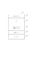
図3は、図2に示したRAM202のメモリマップの一例を示す図であり、印刷管理サービスが、RAM202にロードされ実行可能となった状態のメモリマップである。
FIG. 3 is a diagram illustrating an example of a memory map of the
外部メモリ211から直接RAM202にロードして実行させても良い。さらに、印刷管理サービスをプログラムROM203に記憶しておき、これをメモリマップの一部となすように構成し、直接CPU201で実行することも可能である。また、以上の各装置と同等の機能を実現するソフトウェアをもって、ハードウェア装置の代替として構成することも出来る。
The program may be directly loaded from the
印刷管理サービスは、印刷管理サーバにおいては、印刷ジョブを転送したり、印刷ジョブの印刷先の変更を指示したり、印刷順序を変更したりする指示をするための制御を行う。 The print management service controls the print management server to instruct to transfer a print job, instruct to change the print destination of the print job, or to change the print order.
301は基本I/Oプログラムを記憶するための領域である。基本I/Oプログラムは、印刷管理サーバ101の電源がONされたときに、外部メモリ211からOSがRAM202に読み込まれ、OSの動作を開始させるIPL(イニシャルプログラムローディング)機能などを有しているプログラムである。
302はOS(オペレーティングシステム)を記憶する領域であり、303は印刷管理サービスを記憶する領域である。304は、関係データを記憶する領域である。305はワークエリアで、CPU201が各種のプログラムを実行するための領域である。
An
<ソフトウェア構成図>
次に、本プリントシステムの印刷管理サーバ101のソフトウェア構成について説明する。図4は、印刷管理サーバ101におけるソフトウェア構成の一例を示す図である。また、各ブロックで示されたソフトウェア構成は、図2のCPU201がROM、HDD等に記憶される各種プログラムを実行することにより実現される機能を示す。
<Software configuration diagram>
Next, the software configuration of the
通常、Microsoft Word(登録商標)などの一般的なアプリケーション401は印刷の指示を受け付けると、一連の描画コマンドをOSを介して生成する。OSを介して生成された描画コマンドを受け取ったプリンタドライバ402は、一連の描画コマンドに基づいてデバイス104A〜104Nで解釈可能なPDLファイルを含む印刷ジョブを生成する。また、デバイス104A〜104Nの各々の機種が異なる場合には、場合によっては、各々のデバイスに対応するプリンタドライバ402A〜402Nが、印刷管理サーバ101に具備されることもある。
Normally, when a general application 401 such as Microsoft Word (registered trademark) receives a print instruction, it generates a series of drawing commands via the OS. Upon receiving the drawing command generated via the OS, the printer driver 402 generates a print job including a PDL file that can be interpreted by the devices 104A to 104N based on a series of drawing commands. In addition, when the models of the devices 104A to 104N are different, the
そして、プリンタドライバ402は、デバイスへ生成した印刷ジョブを転送するために該生成した印刷ジョブのデータをプリントスプーラ403に渡す。ここではOSをウィンドウズ(登録商標)と仮定しているのでプリントスプーラ403はウィンドウズ(登録商標)スプーラである。但し、本発明を適用するコンピュータのOSはWindows(登録商標)に限定されるものではなく、描画命令を備えるものであれば他のOSも適用可能であることは言うまでもない。 Then, the printer driver 402 passes the generated print job data to the print spooler 403 in order to transfer the generated print job to the device. Here, since the OS is assumed to be Windows (registered trademark), the print spooler 403 is a Windows (registered trademark) spooler. However, it is needless to say that the OS of the computer to which the present invention is applied is not limited to Windows (registered trademark), and other OS can be applied as long as it has a drawing command.
プリントスプーラ403は、ユーザがユーザインタフェースを介して選択し指示したジョブ制御ポートモニタ404に印刷ジョブを渡して、デバイス104A〜104Nのデバイスに転送させる手順をとる。 The print spooler 403 passes the print job to the job control port monitor 404 selected and instructed by the user via the user interface, and transfers the print job to the devices 104A to 104N.
ここでは、ユーザは予め印刷管理サービス405に印刷ジョブを転送する、ジョブ制御ポートモニタ404を指定して印刷を指示したものとして説明を進める。 Here, the description will proceed on the assumption that the user has designated the job control port monitor 404 to transfer a print job to the print management service 405 and instructed printing in advance.
また、プリンタドライバインタフェースを介して設定された用紙サイズ、ステイプル指示等の印刷設定情報も、ジョブ制御ポートモニタ404に通知される。ジョブ制御ポートモニタ404は上位から渡された印刷ジョブのみならず通知された印刷設定情報も印刷管理サービス405に通知する。 In addition, print setting information such as a paper size and a stapling instruction set via the printer driver interface is also notified to the job control port monitor 404. The job control port monitor 404 notifies the print management service 405 not only of the print job delivered from the upper level but also the notified print setting information.
印刷管理サーバ101、又は、印刷管理サーバ101が利用可能なネットワーク102上の別の情報処理装置のカスタマイズアプリケーション406は、API407を介し、印刷管理サービス405に印刷ジョブを投入する。なお、APIとはAPI:Application Program Interfaceの略語である。
The
印刷管理サービス405は、外部アプリケーションとのインタフェースであるAPI407と、印刷管理部410と、接続管理部420と、印刷ジョブを各デバイスに転送する複数の転送部430と含む。これらの各機能ブロックはソフトウェア的に構成されているものとして示すが、何れかの機能ブロックをハードウェア的に構成しても同様の機能を得ることができる。
The print management service 405 includes an API 407 that is an interface with an external application, a print management unit 410, a connection management unit 420, and a plurality of
印刷管理部410は、現在のジョブ状況を保持するジョブ管理部411と、複数のプリントキューを管理するプリントキュー管理部412と、複数のプリンタポートを管理するプリンタポート管理部413とを含む。各構成部の機能は後述で詳しく説明する。 The print management unit 410 includes a job management unit 411 that holds the current job status, a print queue management unit 412 that manages a plurality of print queues, and a printer port management unit 413 that manages a plurality of printer ports. The function of each component will be described in detail later.
接続管理部420は、現在のデバイスに係る状態を保持するデバイス管理部421と、デバイスとの接続順序を管理する接続順序制御部422と、それら順序を保持する接続順序リストとを備え、本発明の特徴である、印刷先の切り替え処理を制御している。この印刷先の切り替え処理の制御の詳細は後述で説明する。
The connection management unit 420 includes a
<プリントキュー情報>
図5は、ジョブ制御ポートモニタ404からプリントキュー(印刷管理部410の最左上部)で受け付けた印刷ジョブの動作を決めるプリントキュー情報500を示す図である。このプリントキュー情報500は何れかのタイミングで事前にプリントキューに対応して設定されているものとする。
<Print queue information>
FIG. 5 is a diagram illustrating
ここで、プリントキュー情報500の設定内容である、プリンタ名501、プリンタドライバ名502、ポート名503、及びバックアッププリンタ名504について説明する。
Now, the
プリンタ名501は、WindowS(登録商標)のプリンタオブジェクトの名前を示しており、プリンタオブジェクト毎に異なる名前であり、プリンタオブジェクトを識別することができる。プリンタドライバ名502は、プリンタオブジェクトに設定されているプリンタドライバの名前である。ポート名503は、プリンタ名に対応するプリンタポートの名称である。バックアッププリンタ名504は、代行印刷、負荷分散印刷処理等の場合に使用される代行印刷するためのプリンタの名前であり、図5の例のように複数登録可能である。
A
印刷ジョブ投入先のデバイスで紙なし等エラーが発生すると、印刷ジョブを受け付けたプリントキューとプリントキュー情報に設定されている複数のバックアッププリンタを用いて負荷分散印刷処理を行う。具体的には、印刷ジョブを受け付けたプリントキューとプリントキュー情報に設定されている複数のバックアッププリンタの中から、順次転送可能なデバイスに印刷ジョブを転送又は移動し代行印刷を行う。ここで、転送可能なプリンタの決定方法としては、最初に転送可能と判定されるデバイス、予め決められた優先度に従うデバイスを抽出する方法が取られる。 When an error such as no paper occurs in a print job input destination device, load distribution printing processing is performed using a print queue that has received a print job and a plurality of backup printers set in the print queue information. Specifically, the print job is transferred or moved to a sequentially transferable device from among the print queue that has received the print job and a plurality of backup printers set in the print queue information, and performs proxy printing. Here, as a method for determining a printer that can be transferred, a method of extracting a device that is initially determined to be transferable and a device that conforms to a predetermined priority is used.
<プリンタポート情報>
図6は各プリンタへ印刷ジョブを転送するときの動作を決めるプリンタポート情報600を示す図である。図4の印刷管理部410の最左下部の各プリンタポートに対応付けられ、何れかのタイミングで事前に設定される。また、プリンタポート情報600はプリントキューにも対応して設定される。また、図6に示される設定は、プリンタポート毎、プリンタキュー毎に設定可能である。プリンタアドレス601は、印刷ジョブ転送先のデバイスのネットワークアドレスであり、対応するデバイスのIPアドレス又は名前解決(DNS:Domain Name System)で使用されるネームが関連付けられている。プリンタモデル602は、印刷ジョブ転送先のデバイスの種別を示すプリンタモデル名であり、プリンタモデルの違いによる動作差異が発生した際には、プリンタモデルごとの定義を作成し差異を吸収する。この差異吸収に係る処理の詳細な説明は個々では省略する。プロトコル603はデバイスへ印刷ジョブを転送する際の通信プロトコルであり、例えばLPR(Line PRinter deamon Protocol)と呼ばれる、相互通信しながら印刷ジョブを転送するプロトコルや、印刷ジョブを直接転送するRAWプロトコル等がある。
<Printer port information>
FIG. 6 is a diagram showing
本印刷システムの特徴的な設定として、プリンタポート情報600に設定されているデバイス又はジョブ監視にかかわる設定がある。印刷先切り替えモード604は後述のフローチャートで詳しく説明する印刷先切り替えに係る設定フィールドである。連続監視時間605、連続転送数606は、印刷切り替えを行う条件である。
As a characteristic setting of the printing system, there is a setting related to device monitoring or job monitoring set in the
連続監視時間605は、デバイス又は印刷ジョブを連続して監視する上限時間を示す。この連続監視時間605は、ユーザ任意の値に設定可能であり、カスタマイズアプリケーション406が提供す設定画面(不図示)を介しての入力値に基づき設定される。
The
また、連続転送数606は、同じデバイスに対して連続して印刷ジョブを幾つ転送するかの条件を示す。この連続転送数606は、ユーザ任意の値に設定可能であり、カスタマイズアプリケーション406が提供す設定画面(不図示)を介しての入力値に基づき設定される。
The
尚、印刷先の切り替え条件として、連続監視時間605、連続転送数606が示されているが、これに、限定されるものではない。例えば、印刷ジョブ転送サイズ等、各種、特定の条件を含めることができる。
Although the
<ジョブ情報>
図7は一般アプリケーション401もしくはカスタマイズアプリケーション406から投入される印刷ジョブのジョブ情報700であり、HDD211に保存され、ジョブ管理部411によって管理される情報である。
<Job information>
FIG. 7 shows
カスタマイズアプリケーション406からジョブが投入される場合には、図4中のAPI407経由で印刷管理部410に印刷ジョブが入力される。一方、一般アプリケーション経由では、ジョブ制御ポートモニタ404経由で印刷管理部410に印刷ジョブが入力される。印刷管理部410は印刷ジョブを入力するとそれに対応するジョブ情報700を生成し、プリントキューに生成したジョブ情報700を登録する。また、印刷ジョブの実体のデータはジョブ情報700に関連付けられ、図4に図示される如くHDD211に保存される。
When a job is input from the customization application 406, the print job is input to the print management unit 410 via the API 407 in FIG. On the other hand, via a general application, a print job is input to the print management unit 410 via the job control port monitor 404. When a print job is input, the print management unit 410 generates
ジョブ情報700には、ドキュメント名701、印刷管理サービスで発行されるジョブID702、印刷したユーザ名703、ページ数704、ジョブ状態705等が含まれる。また、同ジョブ情報700には、デバイス内で生成されるデバイスジョブID706、スケジューリングの順序を決定する優先度707、完了結果708、および完了時間709も含まれる。
The
ジョブ状態705は、そのときのジョブの状態によって、例えばスプール中、転送中、印刷中、停止中、印刷完了などの状態をとる。
The
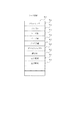
<接続順序リスト>
図8は図4で示した接続順序リスト800の一例である。この接続順序リスト800には、監視対象となるデバイスの識別子及び各デバイスの付属情報が基本的にFIFOで登録されている。この接続順序リスト800又は接続順序リスト800に基づく設定の事を、印刷管理サーバ101による監視対象の順序を管理する為の設定ということで、監視対象キューと呼ぶこともある。そして、この接続順序リスト800におけるデバイスの登録順序に従い、順次、デバイスに関連する状態の監視を実行する。
<Connection order list>
FIG. 8 is an example of the
なお、ここでの”接続”とは上述の接続管理部420の管理に基づく、通信セッションの確立のことを指し、該通信セッションの中で、各種状態の取得や要求等を行うことができる。また、印刷デバイスの監視を中断するとは、確立された通信セッションを切断することを指す。図8に示される接続順序リスト800は、後述の図15のS1502で更新される。
Here, “connection” refers to establishment of a communication session based on the management of the connection management unit 420 described above, and various states can be acquired or requested in the communication session. The interruption of printing device monitoring refers to disconnecting an established communication session. The
接続順序リスト800の横方向の項目には、接続対象プリンタ名、各プリンタキューに登録されている未転送のジョブ数、接続優先度、接続状態、今回の接続ですでに転送したジョブ数である転送済みジョブ数が設定されている。図8中では、1乃至3の接続順番において、デバイスと接続中であり、4番目以降では接続待機中であることが示されている。また、接続中、接続待機中の他にも、一旦接続を切断し再度の接続を待機する「確認待ち」の状態もある。この「確認待ち」は広義で接続待機中に含まれる。
Items in the horizontal direction of the
そして上述の接続管理部420は、この接続順序リスト800に登録(設定)された情報を元に接続順序を決定する。処理の詳細は後述にて説明する。
The connection management unit 420 described above determines the connection order based on the information registered (set) in the
<印刷デバイスの機能ブロック図>
図9は図1で示したデバイス104A〜104Nの構成の一例を示す図である。なお、図中ではハードウェアブロックとソフトウェアブロックとが混在しているが、何れもデバイスの特定の機能を示す。
<Functional block diagram of printing device>
FIG. 9 is a diagram illustrating an example of the configuration of the devices 104A to 104N illustrated in FIG. Note that although hardware blocks and software blocks are mixed in the figure, each indicates a specific function of the device.
デバイスコントローラ901はデバイスの制御を行うモジュールであり、ハードウェアの状態や、投入された印刷ジョブの状態の管理、制御を行う。先の図2で説明したCPU1301及び印刷部I/F1305等に相当する。また、デバイスがMFP(Multi Function Printer)と呼ばれる印刷、コピー、FAX、スキャン等の複数の機能を備える複合機である場合は、該デバイスコントローラ901はそれら全ての機能を統合的に管理、制御するモジュールに該当する。
A device controller 901 is a module that controls devices, and manages and controls the status of hardware and the status of submitted print jobs. This corresponds to the
デバイスストレージ902は、デバイス内に具備、又は相互通信可能に接続された永続記憶領域、もしくは永続記憶装置であり、RAMもしくはHDDといったデータ記憶手段によって実現される。 The device storage 902 is a permanent storage area or a permanent storage device provided in the device or connected to be able to communicate with each other, and is realized by a data storage means such as a RAM or an HDD.
また前述したように、デバイス104A〜104Nは印刷ジョブのスケジュール管理や、後述する印刷ジョブ履歴の保持及び管理を行うデバイススケジューラ103を備えている。デバイススケジューラ103は、接続管理部911、スケジュール管理部912、イベント管理部913、履歴管理部914で構成される。
Further, as described above, the devices 104A to 104N include the
接続管理部911は、印刷管理サービス405との通信を行う複数の接続部および、印刷管理サービス405との接続状況や、印刷管理サービス405から登録されているイベント情報を保持する、後述する接続リスト1000を備える。
The
スケジュール管理部912は、印刷管理サービス405から受け付けた印刷ジョブのリストを管理する部分である。後述するスケジュールリスト1100および、それら印刷ジョブを制御するジョブ制御部を含み、印刷ジョブのスケジューリングを行う。
The schedule management unit 912 is a part that manages a list of print jobs received from the print management service 405. A
イベント管理部913は、デバイスコントローラ901が持つハードウェアの状態を保持し、デバイスコントローラ901からハードウェア状態の変化を受け付け、スケジュール管理部913および接続管理部911を経由して接続している印刷管理サービス405に情報を通知する。
The
またデバイスコントローラ901内の印刷ジョブ状態の変化を受け付け、スケジュール管理部912に通知する。通知を受けたスケジュール管理部912はスケジュールリストに含まれるジョブ状態を更新し、接続している印刷管理サービス405に通知するよう接続管理部911に依頼する。
In addition, a change in the print job status in the device controller 901 is received and notified to the schedule management unit 912. Upon receiving the notification, the schedule management unit 912 updates the job status included in the schedule list and requests the
履歴管理部914は、印刷ジョブの完了履歴を管理するモジュールであり、接続管理部911の指示によって、デバイスストレージ902に履歴ファイルを生成、読み書き、削除を行う。それら履歴ファイルは履歴管理部914によって操作される履歴管理ファイルによって管理される。これら印刷ジョブ履歴の管理処理の詳細は後述する。
The
尚、図9中には示されていないが、デバイス104A〜104Nの各々には、例えば、記録媒体への像形成を行うプリンタエンジン及びプリンタエンジンの各種情報を検知するセンサ機構等も具備されている。これら、プリンタエンジン等については、図3で説明した通りである。
Although not shown in FIG. 9, each of the
<デバイス側における接続リスト1000>
図10は接続管理部911によって生成される接続リスト1000(以降、接続リスト)の一例である。接続リスト1000にはデバイススケジューラ103に通信セッションを張って接続しているコンピュータの固有IDが登録されている。接続リスト1000には複数のコンピュータ(固有ID)が含まれているが、この中の1つが、図1の印刷管理サーバ101である。ここで留意する点として、接続リスト1000へのコンピュータの登録順番は印刷順番を定義するものではない。印刷順番は後述するスケジュールリスト100に基づき決定される。以下、接続リスト1000について、具体的に説明する。
<
FIG. 10 shows an example of a connection list 1000 (hereinafter referred to as a connection list) generated by the
接続リストは、管理ID、印刷管理サービスから通知されるユニークである固有ID、デバイスコントローラから通知されるイベントを要求するかを設定するイベント登録フィールド、及び印刷ジョブ履歴機能を利用するかを設定する履歴モードフィールドからなる。以下では、履歴機能を利用する設定を前提として説明する。 The connection list sets a management ID, a unique ID notified from the print management service, an event registration field for setting whether to request an event notified from the device controller, and whether to use the print job history function. Consists of a history mode field. The following description will be made on the assumption that the history function is used.
また固有IDは、本実施形態ではUUID(Universally Unique IDentifier)と呼ばれる、16進数32桁の数値を用いたが、接続するサービス毎にユニークに識別可能な手段であれば手法は問わない。 In this embodiment, the unique ID is a 32-digit hexadecimal number called UUID (Universally Unique IDentifier). However, any method can be used as long as it can be uniquely identified for each connected service.
<デバイス側におけるスケジュールリスト>
図11はデバイスのスケジュール管理部912によって生成されるスケジュールリスト1100の一例である。スケジュール管理部912には、接続リスト1000に含まれるコンピュータからの印刷ジョブがどのような順番で処理されるかを示すリストである。図11のスケジュールリスト1100では、順番1乃至3に同じコンピュータ(印刷ジョブ発行元)からの印刷ジョブが登録されている。
<Schedule list on the device side>
FIG. 11 shows an example of a
スケジュールリストは、印刷順序、接続リストと共通である固有ID、デバイスコントローラ901より通知されるデバイスジョブID、ジョブ状態および、図7で示したジョブ情報が含まれる。スケジュールリストはスケジュールを受けた順序およびジョブ情報に含まれる優先度707によってスケジューリングされる。
The schedule list includes a printing order, a unique ID common to the connection list, a device job ID notified from the device controller 901, a job status, and job information shown in FIG. The schedule list is scheduled according to the order of receiving the schedule and the
<デバイス側における履歴管理ファイル>
図12には履歴管理部914によって生成される履歴管理ファイル1200および履歴ファイル1220が示されている。
<History management file on device side>
FIG. 12 shows a history management file 1200 and a
履歴管理ファイル1200は、生成された各履歴ファイル情報1210(以後、履歴ファイル情報)のリストである。履歴ファイル情報1210には、履歴ファイルのバージョン1211、最終更新日1212、接続リスト(図10)と共通の固有ID1213、およびデバイスストレージ902に保存されている履歴ファイル名1214が含まれる。この履歴ファイル名1214は履歴ファイルを特定する為の情報として機能する。履歴ファイルには、バージョン1221および図7で示したジョブ情報700が複数個保存される。
The history management file 1200 is a list of generated history file information 1210 (hereinafter, history file information). The
本実施形態では、デバイススケジューラ103により、上述の図12のような履歴情報が生成される。印刷デバイス内で印刷ジョブの状態が変化したことを検知し、印刷ジョブ状態が変化したことを通知すべき印刷管理サーバ101が接続中(監視対象)でなくとも対応出来る。つまり通知すべきジョブ状態変化通知を保存しているので、印刷管理サーバ101から再度ジョブ状態の取得を要求を受けた場合でも、保存しているジョブ状態を通知することが可能となる。
In the present embodiment, the
<印刷ジョブ実行フロー>
次に、本発明の特徴である、印刷管理サーバ101による、大量の複数デバイスの監視および大量の複数印刷ジョブの投入、完了までの追跡を実現するための処理を説明する。
<Print job execution flow>
Next, a feature of the present invention, due to the
まず、概略を述べると、印刷要求に応じて、図13のフローチャートが実行され、ジョブ制御ポートモニタ404によりプリントキュー管理部412が呼び出される。そして、プリントキュー管理部412によりプリンタポート管理部413が呼び出され、図14のフローチャートが実行される。なお、この図13のフローチャートは印刷要求毎、且つ、プリンタポート及びプリンタキュー毎に実行可能される。 First, in outline , the flowchart of FIG. 13 is executed in response to a print request, and the print queue management unit 412 is called by the job control port monitor 404. Then, the printer port management unit 413 is called by the print queue management unit 412 and the flowchart of FIG. 14 is executed. The flowchart of FIG. 13 can be executed for each print request and for each printer port and printer queue.
図14のフローチャートでは、プリントポート管理部413は、接続管理部420にデバイスとの接続に係る処理を依頼し、接続管理部420に図15、図16のフローチャートを夫々実行させる。 In the flowchart of FIG. 14, the print port management unit 413 requests the connection management unit 420 to perform processing related to the connection with the device, and causes the connection management unit 420 to execute the flowcharts of FIGS.
そして、接続管理部420は、図15のフローチャートにより接続先又は接続先候補の各デバイスの状態を監視し、また、図16のフローチャートにより印刷ジョブの転送処理を行う。 Then, the connection management unit 420 monitors the status of each connection destination or connection destination candidate device according to the flowchart of FIG. 15, and performs print job transfer processing according to the flowchart of FIG.
図17、18、19のフローチャートは、図16のフローチャートにおける転送処理の詳細を示す。接続管理部420は、図17、18、19のフローチャートにより、特定の各種条件成立を判定し、接続順序リスト800のデバイス登録に基づく接続先デバイスの切り替え処理を行う。
The flowcharts of FIGS. 17, 18, and 19 show details of the transfer process in the flowchart of FIG. The connection management unit 420 determines that specific various conditions are satisfied according to the flowcharts of FIGS. 17, 18, and 19, and performs connection destination device switching processing based on device registration in the
また、図20のフローチャートは、図15の各デバイスの状態監視に基づき行われる代行印刷処理(S1514)の詳細を示す。以下、各フローチャートの詳細を説明する。 Further, the flowchart of FIG. 20 shows details of the proxy printing process (S1514) performed based on the status monitoring of each device of FIG. Details of each flowchart will be described below.
<印刷管理サーバ101の処理>
図13は、一般アプリケーション401より印刷ジョブを投入された時の、ジョブ制御ポートモニタ404及びプリントキュー管理部412の処理を示したフローチャートである。また、カスタマイズアプリケーション406は生成した印刷ジョブを、ジョブ制御ポートモニタ404と同様の処理によりAPI407を経由してプリントキュー管理部412に投入する。
<Processing of
FIG. 13 is a flowchart illustrating processing of the job control port monitor 404 and the print queue management unit 412 when a print job is input from the general application 401. Further, the customization application 406 inputs the generated print job to the print queue management unit 412 via the API 407 by the same processing as the job control port monitor 404.
まずS1301で、ジョブ制御ポートモニタ404は、プリントスプーラ403よりジョブを受け付け、S1302で、プリントキュー管理部412へジョブ追加通知を行う。この際、プリンタ名を通知する。引き続きジョブ制御ポートモニタ404は、プリントキュー管理部412よりジョブIDが付与されたジョブファイル名を受け付け、S1304でジョブを指定されたファイル名でHDD211に保存する。
In step S1301, the job control port monitor 404 receives a job from the print spooler 403. In step S1302, the job control port monitor 404 notifies the print queue management unit 412 of a job addition. At this time, the printer name is notified. Subsequently, the job control port monitor 404 receives the job file name assigned with the job ID from the print queue management unit 412 and stores the job in the
次にS1305でジョブ制御ポートモニタ404は、プリントキュー管理部412へジョブのスケジュール依頼を通知する。この際、S1303でプリントキュー管理部412から受けたジョブIDを通知する。S1306で、ジョブファイルのHDD211への保存が終了すると、S1307でジョブ制御ポートモニタ404はプリントキュー管理部412へジョブ生成完了を通知し、処理を終了する。この際にも、S1303でプリントキュー管理部412から受けたジョブIDを通知する。
In step S <b> 1305, the job control port monitor 404 notifies the print queue management unit 412 of a job schedule request. At this time, the job ID received from the print queue management unit 412 is notified in step S1303. When the storage of the job file in the
プリントキュー管理部412は、S1311で、ジョブ制御ポートモニタ404からジョブ追加通知を受け付けると、S1312でジョブIDを発行する。そして引き続きS1313でプリンタポートへジョブ追加通知を行う。この際、発行したジョブIDを通知する。次に、S1314で、プリンタポート管理部413よりジョブファイル名を受け付け、S1315でジョブ制御ポートモニタ404へ通知する。 When the print queue management unit 412 receives a job addition notification from the job control port monitor 404 in step S1311, the print queue management unit 412 issues a job ID in step S1312. In step S1313, a job addition notification is sent to the printer port. At this time, the issued job ID is notified. In step S1314, a job file name is received from the printer port management unit 413. In step S1315, the job control port monitor 404 is notified of the job file name.
プリントキュー管理部412は、そしてS1316でジョブ制御ポートモニタ404からジョブスケジュール通知を受け付けると、S1317でプリンタポート管理部413へジョブスケジュール通知を行う。この際、プリントキュー管理部412はプリンタポート管理部413へS1312で発行したジョブIDを通知する。 When the print queue management unit 412 receives a job schedule notification from the job control port monitor 404 in step S1316, the print queue management unit 412 notifies the printer port management unit 413 of the job schedule in step S1317. At this time, the print queue management unit 412 notifies the printer port management unit 413 of the job ID issued in S1312.
S1318で、プリントキュー管理部412はジョブ制御ポートモニタ404からジョブ生成完了通知を受け付けると、S1319でプリンタポート管理部413へジョブ生成完了通知を行い処理を終了する。この際にも、S1312で発行したジョブIDを通知する。 In step S1318, when the print queue management unit 412 receives a job generation completion notification from the job control port monitor 404, in step S1319, the print queue management unit 412 notifies the printer port management unit 413 of job generation completion and ends the processing. Also at this time, the job ID issued in S1312 is notified.
図14は、S1313でプリントキュー管理部412より印刷ジョブが投入された時の、プリンタポート管理部413の処理を示したフローチャートである。 FIG. 14 is a flowchart illustrating processing of the printer port management unit 413 when a print job is input from the print queue management unit 412 in step S1313.
まず、S1401で、プリンタポート管理部413は、プリントキュー管理部412よりジョブ追加通知を受け付けると、S1402で接続管理部420から該プリンタが既に接続処理済みでデバイス状態を取得しているかを確認する。デバイス状態を取得済みでない場合、即ち、デバイスと接続していない場合は、S1403で接続管理部420へ接続開始を通知する。その際、印刷要求の際に指定されたプリンタに基づくプリンタポート情報600を通知する。
First, in step S1401, when the printer port management unit 413 receives a job addition notification from the print queue management unit 412, in step S1402, the printer port management unit 413 confirms whether the printer has already undergone connection processing and has acquired a device state from the connection management unit 420. . If the device status has not been acquired, that is, if it is not connected to the device, the connection management unit 420 is notified of the start of connection in S1403. At that time, the
次にプリンタポート管理部413は、S1404で受け付けたジョブIDからジョブファイル名を発行し、S1405でプリントキュー管理部412へ印刷ジョブに対応するファイル名を通知する。 Next, the printer port management unit 413 issues a job file name from the job ID received in S1404, and notifies the print queue management unit 412 of the file name corresponding to the print job in S1405.
S1406で、プリンタポート管理部413が、プリントキュー管理部412よりスケジュール依頼の通知を受け付けると、S1407で接続管理部420へスケジュール通知を行い処理を終了する。この際に、プリンタポート管理部413は、プリントキュー管理部412より通知されたジョブIDを、接続管理部420へ通知する。 In step S1406, when the printer port management unit 413 receives a schedule request notification from the print queue management unit 412, in step S1407, the printer port management unit 413 notifies the connection management unit 420 of the schedule and ends the processing. At this time, the printer port management unit 413 notifies the connection management unit 420 of the job ID notified from the print queue management unit 412.
図15は、プリンタポート管理部413より接続開始を通知された時の、接続管理部420の処理を示したフローチャートである。 FIG. 15 is a flowchart showing processing of the connection management unit 420 when the printer port management unit 413 is notified of the start of connection.
接続管理部420は、S1501でプリントポート管理部413より接続開始通知を受け付けると、S1502で接続順序リスト登録処理により、図8で説明した接続順序リスト800の最後尾に該接続情報を登録する。このS1502の処理により図8の順序リスト800が更新される。なお、S1502では監視対象キューへの再登録処理として最後尾に登録する例を説明したがこれに限定されない。デバイスに再度接続できる形態であれば最後尾でなくとも良い。例えば、再登録する際に登録対象に所定の優先度を与え、該優先度に従う最前位置に登録される形態でも良い。また、印刷要求で指定デバイスへ転送すべき印刷ジョブが順次生成された場合には、印刷ジョブの出力先のデバイスを監視対象キューとしての接続順序リスト800に順次接続情報が登録されることとなる。
When the connection management unit 420 receives a connection start notification from the print port management unit 413 in step S1501, the connection management unit 420 registers the connection information at the end of the
次にS1503で接続順序リスト800内の接続しているデバイス数と設定された最大接続数を比較する。ここで接続数が最大接続数に達している場合はS1504でデバイス状態を「接続待機中」とし、S1509へ処理を移行する。一方、接続数が最大接続数に達していない場合は、デバイス管理部421において接続処理を実行する。ここで最大接続数はユーザが予め設定画面を介して任意に設定した特定の数に従い決定されるものとする。
In step S1503, the number of connected devices in the
接続処理を開始したデバイス管理部421では、S1505でプリンタポートに対応するデバイススケジューラ103に対して接続通知を行う。この際、設定された固有IDを通知する。接続成功後、S1506でデバイス管理部421はデバイススケジューラ103に対してイベント登録を行なう。そして、S1507で、デバイス管理部421は、S1507でデバイススケジューラ103から通知されるデバイス状態変化イベントの受信を待つ。
In step S <b> 1505, the
デバイス管理部421は、S1508でデバイススケジューラ103よりデバイス状態を取得、又はS1504でデバイス状態を待機中に設定すると、S1508で内部で管理しているデバイス状態を更新する。次にS1510で更新したデバイス状態をプリンタポート管理部413へ通知する。
If the
なお、S1506、S1507のデバイス状態の取得方法としては、例えば、監視対象のデバイスへのポーリング及びポーリング応答待機処理と置き換えても良い。このS1506、S1507の処理は、接続順序リスト800に登録された監視対象デバイスの各種情報をネットワークを介して監視できる方法であれば、各種デバイス監視のための構成を適用することができる。
Note that the device status acquisition method in steps S1506 and S1507 may be replaced with, for example, polling of a monitoring target device and polling response standby processing. As long as the processes of S1506 and S1507 can monitor various types of information on the monitoring target devices registered in the
S1511でデバイス管理部421は、更新したデバイス状態が「切断」又は「接続待機中」又は「確認待ち」であるかを判断し、何れかの状態に該当する場合は処理を終了する。接続中ではない状態は例えば後述の図18の処理によって引き起こされる。一方、何れのデバイス状態にも該当しない場合は、S1512でデバイス状態が「エラー」に該当するかを判断する。ここでの「エラー」とは、印刷出力を続行できない状態を指すものであり、例えば、用紙・トナー等の消耗品切れや、用紙ジャムや、ソフトウェアハングアップ等を指す。S1512で「エラー」に該当しないと判断した場合はS1507へ処理を戻す。一方S1512で「エラー」に該当すると判断した場合は、S1513で、取得したプリンタポート情報にバックアッププリンタが設定されているかを判断する。バックアッププリンタが設定されている場合は、S1514で後述の図20で詳しく説明する代行印刷処理へ処理を移し、処理を終了する。一方、バックアッププリンタが設定されていない場合はS1507へ処理を戻す。
In step S <b> 1511, the
図16は、図14のフローチャートに従いプリンタポート管理部413よりスケジュール依頼を通知された時の、接続管理部420の処理を示すフローチャートである。このプリンタポート管理部413からのスケジュール通知は、上に説明した、図14のフローチャートのS1407に対応する。 FIG. 16 is a flowchart showing the processing of the connection management unit 420 when a schedule request is notified from the printer port management unit 413 according to the flowchart of FIG. The schedule notification from the printer port management unit 413 corresponds to S1407 in the flowchart of FIG. 14 described above.
S1601で、接続管理部420は、プリンタポート管理部413よりスケジュール通知を受け付ける。S1602で、デバイス管理部421において、デバイスとの接続を行いデバイス状態を取得済みかを判断する。より具体的には、S1602でデバイス状態が「切断状態」でないか判断する。デバイス状態を取得済みでない、即ち、デバイス状態が「切断状態」の場合は、S1603でデバイスとの接続を待つ。一方、S1603でYESと判定する場合には、S1604で、接続順序リストの未転送ジョブ数をカウントアップする。
In step S <b> 1601, the connection management unit 420 receives a schedule notification from the printer port management unit 413. In step S1602, the
次にS1605で、デバイス管理部421は、該デバイス状態が「接続待機中」であるかを判断する。デバイス状態が「接続待機中」であった場合は、S1606でスケジュールされる印刷ジョブの優先度設定を確認し、優先度が通常より高い場合はS1607で接続順序制御部422において接続順序リスト変更処理を行う。接続順序リスト変更処理においては、該接続の接続順序リストの優先度設定を変更し、「接続待機中」のリストを優先度順にソートし、処理を終了する。スケジュールされる印刷ジョブの優先度が通常以下であった場合は処理を終了する。
In step S <b> 1605, the
なお、接続順序制御部422で行われる接続順序リスト変更処理において、設定される優先度は、スケジュールされている全てのジョブの優先度の合計、もしくは最大を用いることも可能であるし、平均を用いることも可能である。つまりは、接続順序を優先する条件のポリシーをどこに設定するかによって、振る舞いが決定される。
Note that, in the connection order list change process performed by the connection
一方、デバイス管理部421は、S1605の判断によって、該デバイス状態が「接続待機中」に該当しない場合は、S1608で後述する転送処理を開始する。また、デバイス状態が「確認待ち」である場合には、デバイス管理部421は、S1605でYESと判断する。これは「確認待ち」の状態が広義で接続待機中と同義であるからである。
On the other hand, if it is determined in S1605 that the device status does not correspond to “waiting for connection”, the
図17は、デバイス管理部421において、ジョブ転送処理が開始されたときの、デバイス管理部421の処理を示したフローチャートである。より具体的には、デバイスの監視を中断すべきかを判断する為に、特定の条件成立を判断し、特定の条件が成立しておらず、監視対象を変更しないと判断した場合に印刷ジョブの転送を行う処理を示す。尚、ここでのジョブ転送処理とは、印刷ジョブの転送そのものの処理、及び、印刷ジョブのスケジュール要求の処理等、印刷ジョブの転送に係わる各種処理を含む広義の言葉とする。
FIG. 17 is a flowchart showing processing of the
まずS1701は、デバイス管理部421は、プリンタポートに対応するデバイススケジューラ103に対してスケジュール登録をジョブ情報と共に通知する。
In step S1701, the
次にS1702で、デバイス管理部421は該デバイスの連続監視タイマを開始する。次にS1703でこの連続監視タイマがタイムアップしたかを判断する。該判断はプリンタポート情報600に設定された連続監視時間制限数に達したかを判断することにより行う。S1703で、タイムアップしていると判断場合は、印刷デバイスの監視を中断すべく、S1704で後述の図18ので説明する印刷先切り替え処理を実行する。
In step S1702, the
S1703で、タイムアップしていないと判断した場合には、S1705でデバイススケジューラ103からジョブ状態変化イベントを受信したかを判断する。S1705でジョブ状態変化イベントを受信していない場合は、S1706でタイマをカウントアップしS1703へ処理を戻す。
If it is determined in S1703 that the time is not up, it is determined in S1705 whether a job status change event is received from the
S1707では、デバイス管理部421は、デバイススケジューラ103からジョブ状態変化イベントを受信すると、連続監視タイマをリセットし、受信したイベントがスケジュールアップ、つまり印刷許可であるかをS1708で判断する。このようにS1707の処理により、連続で監視を継続する最大時間に達するまでに、監視を開始している印刷デバイスからの印刷ジョブの状態が変化通知を受けた場合、連続監視時間を初期値に戻し、監視を継続することが出来る。
In step S1707, upon receiving a job state change event from the
受信したジョブ状態変化イベントがスケジュールアップでない場合は、S1709でプリントキューに登録されている印刷ジョブが全て印刷完了しているかを判断する。まだ印刷完了していないジョブが登録されている場合はS1703へ処理を戻す。現在注目しているプリントキューに登録されている印刷ジョブが全て印刷完了している場合は、印刷デバイスの監視を中断すべく、S1710で図18の印刷先切り替え処理を行った後に処理を終了する。 If the received job status change event is not scheduled up, it is determined in step S1709 whether all print jobs registered in the print queue have been printed. If a job that has not yet been printed is registered, the process returns to S1703. If all the print jobs registered in the print queue currently focused on have been printed, the print destination switching process shown in FIG. 18 is performed in step S1710 in order to interrupt the monitoring of the print device, and the process ends. .
デバイス管理部421は、S1708でデバイススケジューラ103よりスケジュールアップを受信したと判断すると、S1711で該ジョブの状態を「転送中」に変更し、プリンタポート管理部413に通知する。次にS1712で連続監視タイマを一時停止状態とし、S1713で転送部430に印刷ジョブの転送開始を通知し、S1714で転送完了を待つ。この際、デバイス管理部421は、転送部430に転送先のプリンタポート情報およびジョブIDを通知する。
If the
転送部430では、デバイス管理部421より転送開始の通知を受け付けると、取得したプリンタポート情報に設定されたプロトコルおよび転送先のアドレスを用いてデバイス104に対して印刷ジョブデータを転送する。その際、取得したジョブIDを元にHDD211から印刷ジョブデータを特定する。転送部430は全ての印刷ジョブのデータ転送が完了すると、転送完了をデバイス管理部421に通知する。
Upon receiving a transfer start notification from the
デバイス管理部421は、S1715で転送部430より転送完了通知を受け付けると、S1716で該ジョブの状態を「転送済み」に変更し、プリンタポート管理部413に通知する。次にS1717で接続順序リスト内の未転送ジョブ数をカウントダウン、転送済みジョブ数をカウントアップする。
Upon receiving a transfer completion notification from the
デバイス管理部421は、S1718でカウントアップされた転送済みジョブ数とプリンタポート情報に設定されている連続転送数と比較する。S1718の判定で連続転送数に達している場合は、S1719で、印刷デバイスの監視を中断すべく、図18の印刷先切り替え処理を実行する。後で詳しく説明するがS1718でNOと判断すると、図18のフローを実行し、S1803でYES(言い換えれば他の待機している登録ジョブがある)と判定するとS1809で最後尾に回す候補のデバイスにおける印刷未完了の印刷ジョブの存在を調べる。印刷未完了の印刷ジョブの存在があると判断するとS1811で最後尾に登録する。そして、S1815で次順(接続中以外のものであり、図8では上から4つ目の順序4が該当)の接続処理を開始指示する。転送済みジョブ数が連続転送数に達していない場合は、S1720で未転送ジョブがまだ残っているかを判断し、残っていない場合は、S1719で図18の印刷先切り替え処理を実行する。一方、S1720の判断でまだ未転送のジョブが残っている場合はS1702に処理を戻す。
The
図18は、印刷先切り替え処理が開始された時の、デバイス管理部421による印刷デバイスの監視中断、及び、監視中断したデバイスを監視対象キュー(接続順序リスト800)に再登録する処理を示したフローチャートである。
FIG. 18 shows processing for monitoring the printing device by the
まず、デバイス管理部421は、S1801で、印刷先切り替え処理を開始すると、接続順序リストの連続送信数をリセットし、次にS1802で連続監視タイマをリセットする。
First, when starting the printing destination switching process in S1801, the
デバイス管理部421は、S1803で接続順序リストに現在「接続待機中」又は「確認待ち」の状態のデバイスがあるかを判断する。該当するデバイスが接続順序リストにない場合は、S1804でプリントキューに完了していないジョブがあるかを判断する。S1805で完了していないジョブが存在する場合は印刷切り替え処理の呼び元に処理を戻す。また、完了していないジョブが存在しない場合は、S1806で連続監視タイマを停止し、S1807でデバイススケジューラ103に登録しているイベントの抹消を指示する。そしてS1808でデバイススケジューラ103に切断を通知しデバイス状態を「切断」に更新して処理を終える。
一方、S1803の判断で、デバイス管理部421は、接続順序リストに現在「接続待機中」もしくは「確認待ち」の状態のデバイスがあった場合は、S1809で監視対象(監視中断対象)のプリントキューに印刷が完了していない他のジョブがあるかを判断する。S1809の判断で印刷が完了していないジョブが存在する場合は、S1810でデバイス状態を「確認待ち」に変更し、S1811で接続順序リストの最後尾にリストを移動する。なお、S1811では監視対象キューへの再登録処理として最後尾に登録する例を説明したがこれに限定されない。デバイスに再度接続できる形態であれば最後尾でなくとも良い。例えば、再登録する際に登録対象に所定の優先度を与え、該優先度に従う最前位置に登録される形態でも良い。このS1811の処理により、一旦監視を中断したデバイスについても再度監視対象キュー(接続順序リスト800)の後尾に再登録するので、再度、監視対象キューに登録された登録状況に従いデバイスを監視できる。
On the other hand, if it is determined in S1803 that the
そしてS1812で連続監視タイマを停止し、S1813で、印刷デバイスの監視を中断すべく、デバイススケジューラ103に登録しているイベントの抹消を指示する。そしてS1814でデバイススケジューラ103に切断を通知し、S1815で接続順序リストの次順にリストされているデバイスへの接続処理開始を指示しデバイス状態を「切断」として処理を終える。
In step S1812, the continuous monitoring timer is stopped. In step S1813, an instruction to delete the event registered in the
図19は、デバイス管理部421において、図8の接続順序リスト800の次順の接続処理が指示されたときの、デバイス管理部421の処理を示したフローチャートである。この図19の処理は、一旦、監視が中断され印刷監視対象キューに再登録され、再度接続処理が行われた場合の処理に対応する。
FIG. 19 is a flowchart showing processing of the
デバイス管理部421は、まずS1901で接続順序リスト800の次順にリストされているデバイスの状態が「確認待ち」であるかを判断する。「確認待ち」でなかった場合は通常の接続処理を行うため、図15のポイント15−1(S1505)へ遷移する。一方「確認待ち」であった場合は、S1902でプリンタポート(印刷管理部410の最左下部)に対応するデバイススケジューラ103に対して接続を行う。この際、設定された固有IDを通知する。接続成功後、S1903でデバイス管理部421は履歴取得通知をデバイススケジューラ103に通知し、デバイススケジューラ103が保持している履歴を取得する。このS1903の処理により、監視対象キューに再登録された印刷デバイスの監視が開始された時に、監視中断時に印刷が完了していないジョブの印刷結果を取得することができる。尚、S1903の取得処理に対応するデバイス側の処理は後述の図22で詳しく説明する。
In step S1901, the
S1904で次に取得した履歴を基にジョブ状態(図7のジョブ情報の705、708、709等)を更新する。
In step S1904, the job status (
S1905でデバイス管理部421は更新されたジョブ状態からプリントキューに登録されている全てのジョブが完了したかを判断する。全てのジョブが完了している場合はS1906で接続順序リストから該デバイスの情報を削除する、次にS1907でデバイススケジューラ103に登録しているイベントの抹消を通知する。そしてS1908でデバイススケジューラ103に切断を通知し、デバイスとの接続状態を「切断」として処理を終える。
In step S1905, the
デバイス管理部421は、プリントキューに登録されているジョブが全て完了していない場合は、S1909でデバイススケジューラ103にイベント登録を通知し、図17のポイント17および図15のポイント15−2へ遷移する。遷移後は、少なくとも図15、図17のフローチャートの処理が以後並行して実行される。
If all the jobs registered in the print queue have not been completed, the
図20は、デバイス管理部421において、代行印刷処理が実行されたときの、デバイス管理部421の処理を示したフローチャートである。
FIG. 20 is a flowchart illustrating processing of the
デバイス管理部421は、代行印刷処理が開始されると、S2001でエラー発生デバイスに対応するプリントキューに登録されている全てのジョブを一時停止する。次にS2002でプリンタポート情報に設定されているバックアッププリンタ情報を取得する。次にS2003でプリンタキューに登録されている全てのジョブを代行先のプリンタにスケジュール登録する。次にS2004で代行元のプリンタキューに登録されている全てのジョブを削除し、削除されたジョブの状態を完了状態とする。そして、S2005で、代行先のデバイスを接続順序リスト800の「接続待機中」又は「確認待ち」の最前列に挿入する。最後にS200で印刷先切り替え処理を実行し代行印刷処理を実現する。
When the proxy printing process is started, the
<デバイススケジューラ103の処理>
図21は、デバイススケジューラ103において、履歴保存処理が発生したときの処理フローである。
<Processing of
FIG. 21 is a processing flow when history saving processing occurs in the
S2101で、デバイススケジューラ103は、デバイスコントローラ901からジョブの完了イベントを受信すると、対応する固有IDを特定する。そして、S2102で特定された固有IDをキーに接続リスト(図10)の登録を確認する。
In step S <b> 2101, upon receiving a job completion event from the device controller 901, the
次にジョブの投入元、つまりはジョブの完了イベントの通知先がイベント登録しているかをS213で判断する。より具体的には、完了イベントに対応する固有IDと接続リストに含まれる固有IDとを比較して一致するか否かを判断する。 Next, in step S213, it is determined whether the job submission source, that is, the notification destination of the job completion event is registered. More specifically, the unique ID corresponding to the completion event is compared with the unique ID included in the connection list to determine whether or not they match.
登録されている判断した場合はS2104で、完了イベント通知を、接続している複数又は単数のコンピュータから固有IDをキーに該当するコンピュータに通知する。そして、処理を終了する。 If it is determined that it has been registered, in S2104, a completion event notification is sent from a plurality of connected computers or a single computer to the computer corresponding to the unique ID as a key. Then, the process ends.
ジョブの完了イベントの通知先がイベント登録していない、又は接続していない場合は、S2105で履歴管理ファイルの中にS2101で特定した完了イベントに対応する固有IDに対応する履歴ファイル情報が登録されているかを判断する。 If the job completion event notification destination is not registered or not connected, the history file information corresponding to the unique ID corresponding to the completion event identified in S2101 is registered in the history management file in S2105. Judgment is made.
登録されている場合は、S2106で、履歴ファイル情報から紐付けられる(1214の履歴ファイル名により)履歴ファイルの最後尾に完了イベントを追記する。ここで追記される完了イベントとはジョブが終了しという履歴である。 If registered, in S2106, a completion event is added to the end of the history file linked with the history file information (by the history file name of 1214). The completed event added here is a history that the job is completed.
登録されていない場合は、S2107で履歴ファイルを新規作成して、完了イベントを追加する。最後にS2108で履歴管理ファイルに新規作成した履歴ファイルを登録し処理を終了する。 If not registered, a new history file is created in S2107 and a completion event is added. Finally, in step S2108, the newly created history file is registered in the history management file, and the process ends.
図22は、デバイススケジューラ103において、印刷管理サービス405より履歴取得依頼を受け付けたときの処理フローである。
FIG. 22 is a processing flow when the
まず、S2001でデバイススケジューラ103は、印刷管理サービスより履歴取得依頼を受け付ける。この履歴取得依頼は図19のS1903の処理に対応する。受信した履歴取得要求には固有IDが含まれており、図11のスケジュールリストを参照することにより、S2202で、履歴管理ファイルから固有IDが一致する履歴ファイルを検索する。そして、S2203で、検索により見つけ出された履歴ファイルよりジョブ完了イベントを生成して印刷管理サービスに通知する。この履歴ファイルには、少なくとも、監視中断時に印刷が完了していなかったジョブの印刷処理結果(印刷完了または印刷未終了)が含まれる。
In step S2001, the
このように上記の各フローチャートを実行することにより、印刷管理サーバ101にかかる負荷を大幅に軽減することができる。一台のサーバをもって大量のデバイスの監視および大量の印刷ジョブの投入、完了までの追跡が可能となる。結果、印刷管理サーバ101に要する大幅なコスト削減を実現できる。
As described above, by executing the flowcharts, the load on the
例えば、上記実施形態と同様の効果を奏するために、遠隔の各拠点に配置される各デバイスに投入された印刷ジョブを一元的に管理する場合、各拠点にプリントサーバを配置しそれらプリントサーバを統合的に管理する統合サーバを更に配置する方法も考えられる。この構成では、統合サーバの負荷を軽減できる。しかしながら、各拠点に配置されるプリントサーバの設置コスト、管理コストが高く、またプリントサーバでトラブルが発生したときに、統合サーバで把握、管理することが困難である。また、複数の拠点のプリントサーバで生成されるジョブ情報を集計する等の新たな処理が発生する。また、デバイスの変更が発生した場合に、各プリントサーバと統合サーバの情報の整合性を保つ煩雑な作業も想定される。本実施形態によれば、例えば上述のような、遠隔の各拠点に配置される各デバイスに投入された印刷ジョブを一元的に管理する場合でも、印刷ジョブの状態監視を行うプリントサーバのコストを抑えることができる。 For example, in order to achieve the same effect as the above-described embodiment, when managing print jobs input to each device arranged at each remote site in a centralized manner, a print server is arranged at each site and the print servers are installed. A method of further arranging an integrated server for integrated management is also conceivable. With this configuration, the load on the integrated server can be reduced. However, the installation cost and management cost of the print server arranged at each base are high, and it is difficult for the integrated server to grasp and manage when trouble occurs in the print server. In addition, new processing such as summing up job information generated by print servers at a plurality of bases occurs. Further, when a device change occurs, a complicated operation for maintaining the consistency of information between each print server and the integrated server is also assumed. According to the present embodiment, for example, the cost of the print server for monitoring the status of the print job can be reduced even when the print job input to each device arranged at each remote site is managed as described above. Can be suppressed.
[他の実施の形態]
以上、様々な実施形態を詳述したが、本発明は、複数の機器から構成されるシステムに適用してもよいし、また、一つの機器からなる装置に適用してもよい。例えば、プリンタ、ファクシミリ、PC、サーバとクライアントとを含むコンピュータシステムなどの如くである。
[Other embodiments]
Although various embodiments have been described in detail above, the present invention may be applied to a system constituted by a plurality of devices, or may be applied to an apparatus constituted by one device. For example, a computer system including a printer, a facsimile, a PC, a server, and a client.
本発明は、前述した実施形態の各機能を実現するソフトウェアプログラムを、システム若しくは装置に対して直接または遠隔から供給し、そのシステム等に含まれるコンピュータが該供給されたプログラムコードを読み出して実行することによっても達成される。 The present invention supplies a software program that implements the functions of the above-described embodiments directly or remotely to a system or apparatus, and a computer included in the system reads and executes the supplied program code. Can also be achieved.
従って、本発明の機能・処理をコンピュータで実現するために、該コンピュータにインストールされるプログラムコード自体も本発明を実現するものである。つまり、上記機能・処理を実現するためのコンピュータプログラム自体も本発明の一つである。 Accordingly, since the functions and processes of the present invention are implemented by a computer, the program code itself installed in the computer also implements the present invention. That is, the computer program itself for realizing the functions and processes is also one aspect of the present invention.
その場合、プログラムの機能を有していれば、オブジェクトコード、インタプリタにより実行されるプログラム、OSに供給するスクリプトデータ等、プログラムの形態を問わない。 In this case, the program may be in any form as long as it has a program function, such as an object code, a program executed by an interpreter, or script data supplied to the OS.
プログラムを供給するための記録媒体としては、例えば、フレキシブルディスク、ハードディスク、光ディスク、光磁気ディスク、MO、CD−ROM、CD−R、CD−RWなどがある。また、記録媒体としては、磁気テープ、不揮発性のメモリカード、ROM、DVD(DVD−ROM,DVD−R)などもある。 Examples of the recording medium for supplying the program include a flexible disk, hard disk, optical disk, magneto-optical disk, MO, CD-ROM, CD-R, and CD-RW. Examples of the recording medium include a magnetic tape, a non-volatile memory card, a ROM, a DVD (DVD-ROM, DVD-R), and the like.
また、プログラムは、クライアントコンピュータのブラウザを用いてインターネットのホームページからダウンロードしてもよい。すなわち、該ホームページから本発明のコンピュータプログラムそのもの、もしくは圧縮され自動インストール機能を含むファイルをハードディスク等の記録媒体にダウンロードしてもよいのである。また、本発明のプログラムを構成するプログラムコードを複数のファイルに分割し、それぞれのファイルを異なるホームページからダウンロードすることによっても実現可能である。つまり、本発明の機能処理をコンピュータで実現するためのプログラムファイルを複数のユーザに対してダウンロードさせるWWWサーバも、本発明の構成要件となる場合がある。 The program may be downloaded from a homepage on the Internet using a browser on a client computer. That is, the computer program itself of the present invention or a compressed file including an automatic installation function may be downloaded from the home page to a recording medium such as a hard disk. It can also be realized by dividing the program code constituting the program of the present invention into a plurality of files and downloading each file from a different homepage. That is, a WWW server that allows a plurality of users to download a program file for realizing the functional processing of the present invention on a computer may be a constituent requirement of the present invention.
また、本発明のプログラムを暗号化してCD−ROM等の記憶媒体に格納してユーザに配布してもよい。この場合、所定条件をクリアしたユーザにのみ、インターネットを介してホームページから暗号化を解く鍵情報をダウンロードさせ、その鍵情報で暗号化されたプログラムを復号して実行し、プログラムをコンピュータにインストールしてもよい。 Further, the program of the present invention may be encrypted and stored in a storage medium such as a CD-ROM and distributed to users. In this case, only users who have cleared the predetermined conditions are allowed to download the key information for decryption from the homepage via the Internet, decrypt the program encrypted with the key information, execute it, and install the program on the computer. May be.
また、コンピュータが、読み出したプログラムを実行することによって、前述した実施形態の機能が実現されてもよい。なお、そのプログラムの指示に基づき、コンピュータ上で稼動しているOSなどが、実際の処理の一部または全部を行ってもよい。もちろん、この場合も、前述した実施形態の機能が実現され得る。 Further, the functions of the above-described embodiments may be realized by the computer executing the read program. Note that an OS or the like running on the computer may perform part or all of the actual processing based on the instructions of the program. Of course, also in this case, the functions of the above-described embodiments can be realized.
さらに、記録媒体から読み出されたプログラムが、コンピュータに挿入された機能拡張ボードやコンピュータに接続された機能拡張ユニットに備わるメモリに書き込まれてもよい。そのプログラムの指示に基づき、その機能拡張ボードや機能拡張ユニットに備わるCPUなどが実際の処理の一部または全部を行ってもよい。このようにして、前述した実施形態の機能が実現されることもある。 Furthermore, the program read from the recording medium may be written in a memory provided in a function expansion board inserted into the computer or a function expansion unit connected to the computer. Based on the instructions of the program, a CPU or the like provided in the function expansion board or function expansion unit may perform part or all of the actual processing. In this way, the functions of the above-described embodiments may be realized.
101 印刷管理サーバコンピュータ
102 イーサネット(登録商標)
103 デバイス
104 デバイススケジューラ
401 一般アプリケーション
402 プリンタドライバ
403 プリントスプーラ
404 ジョブ制御ポートモニタ
405 印刷管理サービス
406 カスタマイズアプリケーション
407 API
410 印刷管理部
420 接続管理部
430 転送部
901 デバイスコントローラ
101 Print
103
410 Print Management Unit 420
Claims (18)
前記印刷デバイスに転送すべき印刷ジョブが生成された場合に、印刷ジョブの出力先の印刷デバイスを監視対象キューに順次登録する登録手段と、
前記印刷デバイスの監視のための接続数が最大接続数に達していない場合、前記登録手段による前記監視対象キューへの印刷デバイスの登録順序に従い印刷デバイスの監視を開始する監視手段と、
前記印刷デバイスに連続で転送された印刷ジョブの数を示す連続転送数、及び、前記印刷デバイスを連続で監視している時間を示す連続監視時間に関する特定の条件が成立したか否かを判定する判定手段と、
前記判定手段の判定に基づき印刷デバイスの監視を一旦中断する監視中断手段と、を有し、
前記登録手段は、監視中断した印刷デバイスに登録されている印刷ジョブの中で完了していない印刷ジョブがある場合に、前記監視中断した印刷デバイスを前記監視対象キューに再登録することを特徴とする情報処理装置。 An information processing apparatus capable of communicating with a plurality of printing devices,
Registration means for sequentially registering the print device that is the output destination of the print job in the monitoring target queue when a print job to be transferred to the print device is generated;
Monitoring means for starting monitoring of the printing device according to the registration order of the printing device in the monitoring target queue by the registration means when the number of connections for monitoring the printing device does not reach the maximum number of connections ;
It is determined whether or not a specific condition regarding a continuous transfer number indicating the number of print jobs continuously transferred to the printing device and a continuous monitoring time indicating a time during which the printing device is continuously monitored is satisfied. A determination means;
Monitoring interruption means for temporarily interrupting monitoring of the printing device based on the determination by the determination means ,
The registration unit re-registers the monitored print device in the monitoring target queue when there is a print job that has not been completed among print jobs registered in the monitored print device. Information processing apparatus.
前記印刷デバイスは、
接続中の情報処理装置を記憶する接続管理手段と、
接続中の情報処理装置から印刷ジョブを受け付ける受信手段と、
印刷デバイス内で印刷ジョブの状態が変化したことを検知する検知手段と、
印刷ジョブ状態が変化したことを、前記接続管理手段に記憶された情報処理装置へ通知する通知手段と、
前記印刷ジョブ状態の変化通知を行う際に、通知すべき情報処理装置が前記接続管理手段に記憶されていない場合、通知すべきジョブ状態変化通知を保存する保存手段とを有し、
前記通知手段は、情報処理装置から前記保存されたジョブ状態の取得を受けた際に、保存しているジョブ状態を通知することを特徴とする印刷システム。 A printing system including the information processing apparatus according to any one of claims 1 to 7 and a printing device,
The printing device is
Connection management means for storing the information processing apparatus being connected;
Receiving means for receiving a print job from the connected information processing apparatus;
Detection means for detecting a change in the status of the print job in the printing device;
Notification means for notifying the information processing apparatus stored in the connection management means that the print job status has changed;
A storage unit that stores a job state change notification to be notified when an information processing device to be notified is not stored in the connection management unit when the print job state change notification is performed;
The notifying unit notifies the stored job status when receiving the stored job status from the information processing apparatus.
前記印刷デバイスに転送すべき印刷ジョブが生成された場合に、印刷ジョブの出力先の印刷デバイスを監視対象キューに順次登録する第1登録工程と、
前記印刷デバイスの監視のための接続数が最大接続数に達していない場合、前記監視対象キューへの印刷デバイスの登録順序に従い印刷デバイスの監視を開始する監視工程と、
前記印刷デバイスに連続で転送された印刷ジョブの数を示す連続転送数、及び、前記印刷デバイスを連続で監視している時間を示す連続監視時間に関する特定の条件が成立したか否かを判定する判定工程と、
前記判定工程の判定に基づき印刷デバイスの監視を一旦中断する監視中断工程と、
監視中断した印刷デバイスに登録されている印刷ジョブの中で完了していない印刷ジョブがある場合に、前記監視中断した印刷デバイスを前記監視対象キューに再登録する第2登録工程を有することを特徴とする監視方法。 A printing device monitoring method in an information processing apparatus capable of communicating with a plurality of printing devices,
A first registration step of sequentially registering print device output destinations of print jobs in the monitoring target queue when a print job to be transferred to the print device is generated;
When the number of connections for monitoring the printing device does not reach the maximum number of connections, a monitoring step of starting monitoring the printing device according to the registration order of the printing device in the monitoring target queue;
It is determined whether or not a specific condition regarding a continuous transfer number indicating the number of print jobs continuously transferred to the printing device and a continuous monitoring time indicating a time during which the printing device is continuously monitored is satisfied. A determination process;
A monitoring interruption step of temporarily stopping monitoring of the printing device based on the determination in the determination step;
A second registration step of re-registering the monitored print device in the monitored queue when there is a print job that has not been completed among print jobs registered in the monitored print device; Monitoring method.
前記印刷デバイスは、
接続中の情報処理装置を接続管理手段に記憶する接続管理工程と、
接続中の情報処理装置から印刷ジョブを受け付ける受信工程と、
印刷デバイス内で印刷ジョブの状態が変化したことを検知する検知工程と、
印刷ジョブ状態が変化したことを前記接続管理手段に記憶された情報処理装置へ通知する通知工程と、
前記印刷ジョブ状態の変化通知を行う際に、通知すべき情報処理装置が前記接続管理手段に記憶されていない場合、通知すべきジョブ状態変化通知を保存手段に保存する保存工程とを有し、
前記通知工程は、情報処理装置から前記保存されたジョブ状態の取得を受けた際に、保存しているジョブ状態を通知することを特徴とする監視方法。 A monitoring method comprising the monitoring method according to claim 9 and a monitoring method using a printing device,
The printing device is
A connection management step of storing the information processing apparatus being connected in the connection management means;
A receiving step for receiving a print job from the connected information processing apparatus;
A detection process for detecting a change in the status of the print job in the printing device;
A notification step of notifying the information processing apparatus stored in the connection management means that the print job status has changed;
A storage step of storing, in the storage unit, a job state change notification to be notified when an information processing apparatus to be notified is not stored in the connection management unit when the print job state change notification is performed;
The notification step of notifying the stored job status when receiving the stored job status from the information processing apparatus.
Priority Applications (5)
| Application Number | Priority Date | Filing Date | Title |
|---|---|---|---|
| JP2006148242A JP4827615B2 (en) | 2006-05-29 | 2006-05-29 | Information processing apparatus, printing system, monitoring method, program, and storage medium |
| US11/749,022 US8804162B2 (en) | 2006-05-29 | 2007-05-15 | Information processing apparatus, printing system, monitoring method, program, and storage medium |
| EP07108853.8A EP1862897B1 (en) | 2006-05-29 | 2007-05-24 | Information processing apparatus, printing system, and monitoring method |
| KR1020070051193A KR100908781B1 (en) | 2006-05-29 | 2007-05-28 | Information processing apparatus, printing system, monitoring method and storage medium |
| CNB2007101064602A CN100514275C (en) | 2006-05-29 | 2007-05-29 | Information processing apparatus, printing system, and monitoring method |
Applications Claiming Priority (1)
| Application Number | Priority Date | Filing Date | Title |
|---|---|---|---|
| JP2006148242A JP4827615B2 (en) | 2006-05-29 | 2006-05-29 | Information processing apparatus, printing system, monitoring method, program, and storage medium |
Publications (2)
| Publication Number | Publication Date |
|---|---|
| JP2007317087A JP2007317087A (en) | 2007-12-06 |
| JP4827615B2 true JP4827615B2 (en) | 2011-11-30 |
Family
ID=38420570
Family Applications (1)
| Application Number | Title | Priority Date | Filing Date |
|---|---|---|---|
| JP2006148242A Expired - Fee Related JP4827615B2 (en) | 2006-05-29 | 2006-05-29 | Information processing apparatus, printing system, monitoring method, program, and storage medium |
Country Status (5)
| Country | Link |
|---|---|
| US (1) | US8804162B2 (en) |
| EP (1) | EP1862897B1 (en) |
| JP (1) | JP4827615B2 (en) |
| KR (1) | KR100908781B1 (en) |
| CN (1) | CN100514275C (en) |
Families Citing this family (18)
| Publication number | Priority date | Publication date | Assignee | Title |
|---|---|---|---|---|
| JP4995001B2 (en) * | 2007-08-15 | 2012-08-08 | キヤノン株式会社 | Image processing apparatus, information processing apparatus, log processing method, method, program |
| JP2009297994A (en) * | 2008-06-12 | 2009-12-24 | Ricoh Co Ltd | Printing apparatus, printing system and program |
| JP2010052384A (en) * | 2008-08-29 | 2010-03-11 | Ricoh Co Ltd | Image forming apparatus, print control method, and program |
| JP5319237B2 (en) * | 2008-10-28 | 2013-10-16 | キヤノン株式会社 | Printing system and control method thereof |
| JP5424765B2 (en) * | 2009-07-28 | 2014-02-26 | キヤノン株式会社 | Monitoring device and information processing method |
| JP5561976B2 (en) | 2009-09-11 | 2014-07-30 | キヤノン株式会社 | Information processing apparatus, information processing apparatus control method, and program |
| US8330984B2 (en) | 2010-03-18 | 2012-12-11 | Emerge Paint Management, LLC | Field metering patrol system and method for metering and monitoring printers |
| US8314965B2 (en) | 2010-03-18 | 2012-11-20 | Emerge Print Management, Llc | Patrol device field installation notification method and system |
| JP5195856B2 (en) * | 2010-09-20 | 2013-05-15 | ブラザー工業株式会社 | Printing system and information processing apparatus |
| JP5246238B2 (en) * | 2010-09-30 | 2013-07-24 | ブラザー工業株式会社 | Printing system, printing control apparatus, and printing management system |
| US9600212B2 (en) | 2010-10-29 | 2017-03-21 | Ricoh Company, Ltd. | Receipt verification of print jobs in an automated document factory environment |
| JP5748557B2 (en) * | 2011-05-18 | 2015-07-15 | キヤノン株式会社 | Information processing apparatus, program, and control method |
| US8830971B1 (en) * | 2011-07-26 | 2014-09-09 | Sprint Spectrum L.P. | Control of maximum number of concurrent local device connections for a mobile hotspot |
| JP6142527B2 (en) * | 2012-12-27 | 2017-06-07 | 株式会社リコー | Setting information management program, information processing apparatus, and setting information management method |
| CN106170758B (en) * | 2013-10-31 | 2022-08-05 | 企业服务发展公司有限责任合伙企业 | Monitoring a printer |
| CN103986623A (en) * | 2014-05-28 | 2014-08-13 | 山东超越数控电子有限公司 | Automatic hardware equipment monitoring system based on domestic operating system |
| JP6117165B2 (en) * | 2014-10-21 | 2017-04-19 | 京セラドキュメントソリューションズ株式会社 | Image forming apparatus, image forming system, and job management program |
| JP7447534B2 (en) * | 2020-02-19 | 2024-03-12 | セイコーエプソン株式会社 | Information processing device, information processing program, information processing terminal, and information processing method |
Family Cites Families (43)
| Publication number | Priority date | Publication date | Assignee | Title |
|---|---|---|---|---|
| US4575817A (en) * | 1983-06-27 | 1986-03-11 | International Business Machines Corporation | Switching of programming routine supporting storage stacks |
| JP3493331B2 (en) * | 1993-04-28 | 2004-02-03 | 株式会社日立製作所 | TV conversation monitoring method |
| JP3854699B2 (en) * | 1996-12-27 | 2006-12-06 | キヤノン株式会社 | Printing system and printing interruption method |
| US5970224A (en) | 1997-04-14 | 1999-10-19 | Xerox Corporation | Multifunctional printing system with queue management |
| US6473192B1 (en) * | 1997-09-18 | 2002-10-29 | Canon Kabushiki Kaisha | Job processing apparatus |
| JP3786152B2 (en) * | 1997-11-14 | 2006-06-14 | セイコーエプソン株式会社 | Printing system, printing method, and printer |
| JP3065053B2 (en) * | 1998-01-06 | 2000-07-12 | セイコーエプソン株式会社 | Device monitoring system, local monitoring device, integrated monitoring device, device monitoring method, and computer-readable medium storing program |
| US6349304B1 (en) * | 1998-12-09 | 2002-02-19 | International Business Machines Corporation | Graphical interface for copying settings from network source device to network target devices without transmitting values not usable for features supported by network target devices |
| JP4392919B2 (en) * | 1998-12-24 | 2010-01-06 | キヤノン株式会社 | Print control apparatus, print control method, recording medium storing print control program, and print control program product |
| JP2001175440A (en) * | 1999-12-20 | 2001-06-29 | Canon Inc | Data processor and image recording device and method for controlling the same and storage medium |
| WO2001050266A1 (en) * | 1999-12-30 | 2001-07-12 | Computer Associates Think, Inc. | System and method for topology based monitoring of networking devices |
| WO2001077809A1 (en) * | 2000-04-07 | 2001-10-18 | Seiko Epson Corporation | Control of distributed printers |
| JP3788184B2 (en) | 2000-04-07 | 2006-06-21 | セイコーエプソン株式会社 | Distributed printing control apparatus, distributed printing control method, and recording medium |
| US6748471B1 (en) * | 2000-10-16 | 2004-06-08 | Electronics For Imaging, Inc. | Methods and apparatus for requesting and receiving a print job via a printer polling device associated with a printer |
| JP4420421B2 (en) * | 2001-03-19 | 2010-02-24 | キヤノン株式会社 | Information processing apparatus and control method thereof |
| JPWO2004009362A1 (en) * | 2002-07-19 | 2005-11-17 | セイコーエプソン株式会社 | Printing system |
| GB2394799B (en) * | 2002-07-31 | 2006-01-25 | Hewlett Packard Co | Improvements relating to mobile printing |
| JP3903024B2 (en) * | 2002-08-05 | 2007-04-11 | キヤノン株式会社 | Output management method and information processing apparatus |
| JP3675441B2 (en) * | 2002-11-28 | 2005-07-27 | セイコーエプソン株式会社 | Digital multifunction device and printer |
| JP2004220565A (en) * | 2002-12-27 | 2004-08-05 | Seiko Epson Corp | Distributed printing system, distributed printing method, distributed printing program, printer and printer management server |
| JP3774702B2 (en) * | 2003-02-12 | 2006-05-17 | キヤノン株式会社 | Print control program and information processing apparatus |
| JP2004280218A (en) * | 2003-03-13 | 2004-10-07 | Oki Data Corp | Printing system and printing method |
| US7567360B2 (en) * | 2003-03-27 | 2009-07-28 | Canon Kabushiki Kaisha | Image forming system, method and program of controlling image forming system, and storage medium |
| US7471407B2 (en) * | 2003-06-24 | 2008-12-30 | Sharp Laboratories Of America, Inc. | Systems and methods for monitoring an imaging job using implicit address discovery |
| JP3944133B2 (en) * | 2003-07-25 | 2007-07-11 | キヤノン株式会社 | Information processing apparatus, information processing method, program, and computer-readable storage medium |
| US20050024664A1 (en) * | 2003-07-30 | 2005-02-03 | Schmidt William Randolph | Printer formatter with print server |
| JP2005124124A (en) * | 2003-09-26 | 2005-05-12 | Victor Co Of Japan Ltd | Monitor system |
| JP4006392B2 (en) * | 2003-12-03 | 2007-11-14 | キヤノン株式会社 | Information processing apparatus and control program |
| JP3793197B2 (en) * | 2003-12-03 | 2006-07-05 | キヤノン株式会社 | Information processing apparatus, information processing method, information processing program, and storage medium |
| JP3927949B2 (en) * | 2003-12-10 | 2007-06-13 | キヤノン株式会社 | Information processing apparatus, load distribution printing method, program, and storage medium |
| JP3962720B2 (en) | 2003-12-15 | 2007-08-22 | キヤノン株式会社 | Information processing apparatus, information processing method, computer program, and computer-readable storage medium |
| KR100574023B1 (en) * | 2004-01-20 | 2006-04-26 | 삼성전자주식회사 | The device of transferring printing data using multiplex virtual connections and method thereof |
| JP2005267544A (en) * | 2004-03-22 | 2005-09-29 | Fuji Xerox Co Ltd | Printer managing method and device, and program |
| JP3977356B2 (en) * | 2004-06-09 | 2007-09-19 | キヤノン株式会社 | Information processing apparatus and control method thereof |
| JP4498215B2 (en) * | 2004-06-21 | 2010-07-07 | キヤノン株式会社 | Image forming apparatus monitoring system, image forming apparatus, control method therefor, and program |
| JP2006056069A (en) * | 2004-08-18 | 2006-03-02 | Canon Inc | Printing control unit and printing control method |
| US7649645B2 (en) * | 2005-06-21 | 2010-01-19 | Xerox Corporation | Method of ordering job queue of marking systems |
| US8064081B2 (en) * | 2004-11-26 | 2011-11-22 | Canon Kabushiki Kaisha | Print system and printing method for transmitting print data from a host device to an image forming apparatus by radio communication and performing printing |
| JP4708993B2 (en) * | 2005-01-14 | 2011-06-22 | キヤノン株式会社 | Printing system, control method, and program |
| JP4906469B2 (en) * | 2005-11-14 | 2012-03-28 | キヤノン株式会社 | Printing system, job processing method, storage medium, program |
| US7697861B2 (en) * | 2005-12-28 | 2010-04-13 | Ricoh Company, Limited | Printing apparatus and image forming apparatus |
| JP4626527B2 (en) * | 2006-02-06 | 2011-02-09 | 株式会社日立製作所 | Print processing system and print processing apparatus |
| JP4857102B2 (en) * | 2006-12-22 | 2012-01-18 | キヤノン株式会社 | Information processing apparatus, job processing method, program, and storage medium |
-
2006
- 2006-05-29 JP JP2006148242A patent/JP4827615B2/en not_active Expired - Fee Related
-
2007
- 2007-05-15 US US11/749,022 patent/US8804162B2/en not_active Expired - Fee Related
- 2007-05-24 EP EP07108853.8A patent/EP1862897B1/en not_active Expired - Fee Related
- 2007-05-28 KR KR1020070051193A patent/KR100908781B1/en not_active IP Right Cessation
- 2007-05-29 CN CNB2007101064602A patent/CN100514275C/en not_active Expired - Fee Related
Also Published As
| Publication number | Publication date |
|---|---|
| US8804162B2 (en) | 2014-08-12 |
| CN100514275C (en) | 2009-07-15 |
| KR20070114645A (en) | 2007-12-04 |
| CN101082855A (en) | 2007-12-05 |
| JP2007317087A (en) | 2007-12-06 |
| KR100908781B1 (en) | 2009-07-22 |
| US20070273922A1 (en) | 2007-11-29 |
| EP1862897A3 (en) | 2012-01-25 |
| EP1862897B1 (en) | 2017-05-03 |
| EP1862897A2 (en) | 2007-12-05 |
Similar Documents
| Publication | Publication Date | Title |
|---|---|---|
| JP4827615B2 (en) | Information processing apparatus, printing system, monitoring method, program, and storage medium | |
| JP4857102B2 (en) | Information processing apparatus, job processing method, program, and storage medium | |
| JP5319237B2 (en) | Printing system and control method thereof | |
| JP5595035B2 (en) | Information processing apparatus, method and program | |
| JP3854963B2 (en) | Information processing apparatus, printing system, load balancing printing method, and control program | |
| JP2004054909A (en) | Information processor, printing system, print control method for information processor, and print control program | |
| JP3774702B2 (en) | Print control program and information processing apparatus | |
| JP3833213B2 (en) | Information processing apparatus, printing system, load distribution printing method, program, and storage medium | |
| JP4999619B2 (en) | Image processing apparatus and print request method | |
| JP2010204746A (en) | Print control device, control method, and program | |
| JP4579799B2 (en) | Image forming apparatus, control method therefor, program, and image forming system | |
| JP2008059372A (en) | Printing controller and its method | |
| JP3927949B2 (en) | Information processing apparatus, load distribution printing method, program, and storage medium | |
| JP2007069359A (en) | Image forming apparatus, its controlling method, program and image forming system | |
| JP2008097226A (en) | Information processing device and method | |
| JP4618778B2 (en) | Printing apparatus, network connection apparatus, printing control method, and printing control program | |
| JP2007025970A (en) | Pull print system | |
| JP2008107921A (en) | Pull print server and its control method | |
| JP2007004680A (en) | Printing control device, printing control method and printing control program | |
| JP3420482B2 (en) | Information processing apparatus, network print system, print control method, and storage medium storing program | |
| JP2007334608A (en) | Image processing apparatus and job management method | |
| JP2008059371A (en) | Printing controller and its method | |
| JP2005333447A (en) | Information processor | |
| JP4174523B2 (en) | Information processing apparatus, printing system, load distribution printing method, program, and storage medium | |
| JP2004295357A (en) | Print processing program for performing print processing with department management, information processor, method for processing information and storage medium |
Legal Events
| Date | Code | Title | Description |
|---|---|---|---|
| A621 | Written request for application examination |
Free format text: JAPANESE INTERMEDIATE CODE: A621 Effective date: 20090529 |
|
| RD04 | Notification of resignation of power of attorney |
Free format text: JAPANESE INTERMEDIATE CODE: A7424 Effective date: 20100201 |
|
| RD01 | Notification of change of attorney |
Free format text: JAPANESE INTERMEDIATE CODE: A7421 Effective date: 20100630 |
|
| A131 | Notification of reasons for refusal |
Free format text: JAPANESE INTERMEDIATE CODE: A131 Effective date: 20110510 |
|
| A521 | Written amendment |
Free format text: JAPANESE INTERMEDIATE CODE: A523 Effective date: 20110711 |
|
| TRDD | Decision of grant or rejection written | ||
| A01 | Written decision to grant a patent or to grant a registration (utility model) |
Free format text: JAPANESE INTERMEDIATE CODE: A01 Effective date: 20110906 |
|
| A01 | Written decision to grant a patent or to grant a registration (utility model) |
Free format text: JAPANESE INTERMEDIATE CODE: A01 |
|
| A61 | First payment of annual fees (during grant procedure) |
Free format text: JAPANESE INTERMEDIATE CODE: A61 Effective date: 20110913 |
|
| FPAY | Renewal fee payment (event date is renewal date of database) |
Free format text: PAYMENT UNTIL: 20140922 Year of fee payment: 3 |
|
| FPAY | Renewal fee payment (event date is renewal date of database) |
Free format text: PAYMENT UNTIL: 20140922 Year of fee payment: 3 |
|
| LAPS | Cancellation because of no payment of annual fees |