JP4823364B2 - Game machine - Google Patents
Game machine Download PDFInfo
- Publication number
- JP4823364B2 JP4823364B2 JP2010004204A JP2010004204A JP4823364B2 JP 4823364 B2 JP4823364 B2 JP 4823364B2 JP 2010004204 A JP2010004204 A JP 2010004204A JP 2010004204 A JP2010004204 A JP 2010004204A JP 4823364 B2 JP4823364 B2 JP 4823364B2
- Authority
- JP
- Japan
- Prior art keywords
- data
- reach
- symbol
- variable display
- data table
- Prior art date
- Legal status (The legal status is an assumption and is not a legal conclusion. Google has not performed a legal analysis and makes no representation as to the accuracy of the status listed.)
- Expired - Fee Related
Links
Images


Description
本発明は、たとえば、パチンコ遊技機やコイン遊技機あるいはスロットマシン等で代表される遊技機に関し、詳しくは、制御用のプロセッサを有する制御手段を含む遊技機に関する。 The present invention relates to a gaming machine represented by, for example, a pachinko gaming machine, a coin gaming machine, or a slot machine, and more particularly to a gaming machine including a control means having a control processor.
この種の遊技機において、従来から一般的に知られているものに、たとえば、制御用のプロセッサを有するマイクロコンピュータ等の制御手段が設けられ、遊技者の操作に応じてその制御手段により遊技制御が行なわれるように構成されたものがあった。そしてこの種の遊技機において、たとえば、複数種類の動作を実行可能な動作装置の一例として、表示状態が変化可能な可変表示装置が設けられたものがあった。 In this type of gaming machine, conventionally known control means such as a microcomputer having a control processor is provided in what is generally known, and game control is performed by the control means in accordance with the player's operation. There was something configured to be done. In this type of gaming machine, for example, as an example of an operation device capable of executing a plurality of types of operations, there is one provided with a variable display device capable of changing a display state.
この可変表示装置は、たとえば、図柄等からなる複数種類の識別情報が可変表示された後停止表示されるように構成されており、この可変表示装置の表示結果が予め定められた特定の表示態様になれば、遊技機の遊技状態が遊技者にとって有利な状態に制御されるように構成されていた。 The variable display device is configured to stop display after a plurality of types of identification information including symbols and the like are variably displayed, for example, and a display result of the variable display device is determined in a specific display mode. If so, the gaming state of the gaming machine is controlled so as to be advantageous to the player.
この可変表示装置は、たとえば前記複数種類の識別情報が可変表示されるのであるが、その停止時における表示結果としてどの種類の識別情報を停止表示させるか等に応じて、可変表示時間がまちまちとなる場合があり、また、遊技状態に応じて、可変表示速度を通常より遅くする等の制御が行なわれていた。すなわち、この従来の遊技機における動作装置(可変表示装置)は、可変表示速度が異なる等の複数種類の動作を実行可能であり、それぞれの動作が複数種類の識別情報を可変表示するという点で類似しているのである。 In this variable display device, for example, the plurality of types of identification information are variably displayed. Depending on which type of identification information is to be stopped and displayed as a display result at the time of stoppage, the variable display time varies. In addition, depending on the gaming state, control such as making the variable display speed slower than usual has been performed. That is, the operation device (variable display device) in this conventional gaming machine can execute a plurality of types of operations such as variable display speeds, and each operation variably displays a plurality of types of identification information. It is similar.
図29は、従来の遊技機における前記動作装置として可変表示装置を制御するためのデータを格納しているテーブルである。この従来の遊技機の可変表示装置は、たとえば、図柄番号が0〜14の15種類の識別情報を可変表示するように構成されており、可変表示装置の停止時にどの識別情報を表示させるかに応じて15種類の可変表示に関する動作時間が存在するようになるために、その15種類の動作時間をそれぞれのテーブルに配列して記憶している。
FIG. 29 is a table storing data for controlling a variable display device as the operation device in a conventional gaming machine. This conventional variable display device of a gaming machine is configured to variably display 15 types of identification information having
そして図29(A)に示す第1テーブルでは、たとえば速い速度で複数種類の識別情報を可変表示して比較的短時間の間に識別情報を停止表示させるものであるために、各動作時間が比較的短いものとなっている。(B)に示す第2テーブルでは、遅い速度で可変表示させて比較的長い時間可変表示させた後識別情報を停止表示させるものであるために比較的長い動作時間が記憶されている。そしてこの第2テーブルの動作時間に基づいて可変表示装置が制御される場合には、その可変表示装置の停止時に表示される識別情報が15種類の識別情報のうちの或る3種類の識別情報に限られるように構成されているために、動作時間もその3種類の識別情報に応じた3種類の時間しか存在しないために、第2テーブルでは、その3種類の動作時間を記憶している。 In the first table shown in FIG. 29A, for example, a plurality of types of identification information are variably displayed at a high speed and the identification information is stopped and displayed in a relatively short time. It is relatively short. In the second table shown in (B), since the identification information is stopped and displayed after being variably displayed at a slow speed and variably displayed for a relatively long time, a relatively long operation time is stored. When the variable display device is controlled based on the operation time of the second table, the identification information displayed when the variable display device is stopped is certain three types of identification information among the 15 types of identification information. Since there are only three types of operation time corresponding to the three types of identification information, the second table stores the three types of operation time. .
図30(A)は、従来の遊技機における前記可変表示装置の動作時間を選択決定するためのプログラムモジュールを示すフローチャートである。まずステップS(以下単にSという)A1により、遊技状態に応じて可変表示装置の可変表示速度を選択する処理がなされ、SA2に進み、その後選択された可変表示速度に対応するテーブル(図29の第1テーブル,第2テーブルのうちのいずれかのテーブル)を選択して決定する処理がなされる。そしてSA3に進み、その選択されたテーブルに対応するテーブルルックアップモジュールにジャンプする処理がなされて制御が終了する。 FIG. 30A is a flowchart showing a program module for selecting and determining the operation time of the variable display device in a conventional gaming machine. First, in step S (hereinafter simply referred to as S) A1, processing for selecting the variable display speed of the variable display device is performed according to the gaming state, the process proceeds to SA2, and then a table corresponding to the selected variable display speed (FIG. 29). A process of selecting and determining one of the first table and the second table is performed. Then, the process proceeds to SA3, a process of jumping to the table lookup module corresponding to the selected table is performed, and the control is finished.
図30(B)は、図29(A)に示された第1テーブルをルックアップするためのテーブルルックアップモジュールを示すフローチャートである。まずSA4により、第1テーブルの先頭アドレス(Addr)がセットされ、次にSA5に進み、オフセットアドレス=予定停止図柄(可変表示装置の停止時に表示する予定となっている図柄)の番号×2が算出される。次にSA6に進み、有効アドレス=Addr+オフセットアドレスの算出がなされる。そしてSA7に進み、算出された有効アドレスの箇所に記録されている動作時間を読出してそれをセットする処理がなされる。 FIG. 30B is a flowchart showing a table lookup module for looking up the first table shown in FIG. First, the head address (Addr) of the first table is set by SA4, and then the process proceeds to SA5, where the offset address = scheduled stop symbol (symbol scheduled to be displayed when the variable display device is stopped) × 2 Calculated. Next, the process proceeds to SA6, where effective address = Addr + offset address is calculated. Then, the process proceeds to SA7, where the operation time recorded at the calculated effective address is read and set.
図30(C)は、図29(B)に示された第2テーブルをルックアップするためのテーブルルックアップモジュールを示すフローチャートである。まずSA8により、第2テーブルの先頭アドレス(Addr)をセットする処理がなされ、SA9に進み、予定停止図柄の図柄番号が14であるか否かの判断がなされ、14でない場合にはSA10に進み、オフセットアドレス=予定停止図柄×2が算出されてSA12に進む。一方、SA9により予定停止図柄の図柄番号が14であると判断された場合にはSA11に進み、オフセットアドレス=4とする処理がなされる。次にSA12に進み、有効アドレス=Addr+オフセットアドレス の算出が行なわれて、SA13に進み、有効アドレスの箇所に記憶されている動作時間を読出してセットする処理がなされる。 FIG. 30C is a flowchart showing a table lookup module for looking up the second table shown in FIG. First, the process of setting the top address (Addr) of the second table is performed by SA8, and the process proceeds to SA9 to determine whether or not the symbol number of the scheduled stop symbol is 14, and if not, the process proceeds to SA10. , Offset address = scheduled stop symbol × 2 is calculated, and the process proceeds to SA12. On the other hand, if it is determined by SA9 that the symbol number of the scheduled stop symbol is 14, the process proceeds to SA11 and processing for setting the offset address = 4 is performed. Next, the process proceeds to SA12, where the effective address = Addr + offset address is calculated, and the process proceeds to SA13, where the operation time stored at the effective address is read and set.
このように、従来の遊技機においては、動作装置の一例の可変表示装置の動作時間データを記憶しているテーブルが複数設けられており、そのテーブルデータをルックアップするテーブルルックアップモジュールのプログラムを複数設けざるを得なかった。 As described above, in a conventional gaming machine, a plurality of tables storing operation time data of a variable display device as an example of an operation device are provided, and a table lookup module program for looking up the table data is provided. There was no choice but to have more than one.
すなわち、図31に示すように、従来の遊技機においては、テーブル1〜テーブルnが設けられている場合に、それぞれのテーブルをルックアップするプログラムモジュールも1〜nのn個が必要となっていた。その関係上、制御用のプログラムを記憶しているROM等のメモリのプログラム記憶領域に多くのテーブルルックアップモジュールを記憶させなければならず、プログラム記憶領域があまり有効利用できないという欠点があった。 That is, as shown in FIG. 31, in a conventional gaming machine, when tables 1 to n are provided, n program modules that look up each table are required to be n. It was. For this reason, many table lookup modules have to be stored in a program storage area of a memory such as a ROM storing a control program, and the program storage area cannot be used effectively.
この従来の欠点が生ずる原因を追求したところ、図29の(A)と(B)に示された第1テーブルと第2テーブルとにおいて、図柄番号14の動作時間データが、第1テーブルではそのテーブル内で15番目の配列位置に記憶されている一方、第2テーブルでは3番目の配列位置に記憶されており、同じ種類の動作時間データであるにもかかわらずそれぞれのテーブル内での配列位置が異なっているために、図30のSA5,SA10とSA11で示すように、それぞれ別々の演算式を用いなければテーブル参照できないということが原因になっていることを突き止めた。さらに、或るデータテーブルと他のデータテーブルとで異なった種類のデータを有する場合において、前記或るデータテーブル内での前記異なった種類のデータの配列位置と前記他のデータテーブル内での前記異なった種類のデータの配列位置とが同じである場合にも、やはり同じ演算式ではテーブル参照できないということも見出した。
In pursuit of the cause of this conventional defect, the operation time data of
本発明は、メモリの記憶領域を有効利用できない原因が、前述したテーブルのデータ配列構造にあることを新たに発見したことに基づいて考え出された全く新規な発明であり、請求項1に記載の本発明の目的は、ともに、メモリの記憶領域を有効活用することのできる遊技機を提供することである。 The present invention is a completely new invention that has been conceived based on the newly discovered fact that the storage area of the memory cannot be used effectively in the data array structure of the table described above. It is an object of the present invention to provide a gaming machine that can effectively use a storage area of a memory.
請求項1に記載の本発明は、複数種類の識別情報を可変表示可能な可変表示装置と、制御用のプロセッサを有する制御手段とを含み、前記可変表示装置の表示結果が特定表示結果となったときに特定遊技状態に制御可能となる遊技機であって、
前記プロセッサを動作させるための制御用プログラムを格納するプログラム格納部と、
前記プロセッサによる制御のための複数種類のデータが配列されたデータテーブルを複数格納するデータ格納部とを含み、
前記プログラム格納部は、複数のデータテーブルのうちの所望のデータテーブルを選択し、該データテーブル内のデータを検索する検索プログラムモジュールを格納しており、
前記複数のデータテーブルは、或るデータテーブルと他のデータテーブルとで同種類のデータを有する場合に、前記或るデータテーブル内での前記同種類のデータの配列位置と前記他のデータテーブル内での前記同種類のデータの配列位置とが同じデータ配列構造となるように統一され、共通の前記検索プログラムモジュールにより前記或るデータテーブルと前記他のデータテーブルとを検索可能となるように構成されており、
前記データ格納部は、前記可変表示装置のリーチ表示動作のためのデータが配列されたデータテーブルを、複数種類のリーチ表示動作に対応して複数格納しており、
前記プロセッサは、前記複数種類のリーチ表示動作のうちから前記可変表示装置に実行させるリーチ表示動作を選択して該選択されたリーチ表示動作に対応するデータテーブルを選択し、該選択されたデータテーブル内のデータに従って前記可変表示装置を制御する。
The present invention of
A program storage unit for storing a control program for operating the processor;
A data storage unit that stores a plurality of data tables in which a plurality of types of data for control by the processor are arranged,
The program storage unit stores a search program module that selects a desired data table from among a plurality of data tables and searches for data in the data table,
When the plurality of data tables have the same type of data in a certain data table and another data table, the arrangement position of the same type of data in the certain data table and the other data table Are arranged so that the arrangement position of the same kind of data in the same data arrangement structure is the same, and the certain data table and the other data table can be searched by the common search program module Has been
The data storage unit stores a plurality of data tables in which data for reach display operations of the variable display device are arranged corresponding to a plurality of types of reach display operations,
The processor selects a reach display operation to be executed by the variable display device from the plurality of types of reach display operations, selects a data table corresponding to the selected reach display operation, and selects the selected data table The variable display device is controlled in accordance with the data within.
請求項1に記載の本発明によれば、複数のデータテーブルが、共通の前記検索プログラムモジュールにより検索可能であるために、複数のデータテーブルを簡単に参照しやすくなり、プログラム格納部を節約することが可能となる。また、複数種類のリーチ表示動作を実行可能な可変表示装置の表示動作のためのデータが配列されたデータテーブルが、前記複数種類のリーチ表示動作に対応して複数格納されており、その複数種類のリーチ表示動作のうちから前記可変表示装置に実行させる可変表示動作が選択されてその選択されたリーチ表示動作に対応するデータテーブルが選択され、その選択されたデータテーブル内のデータに従って前記可変表示装置が制御されるために、前記可変表示装置を制御するためのプログラムを小さなもので構成することが可能となり、プログラム格納部を節約することができる。
請求項2に記載の本発明は、前記可変表示装置において、前記リーチ表示動作として前記識別情報とは異なるキャラクタ同士が作用し合う画像を表示することによって前記識別情報の可変表示を終了させる演出が可能である。
According to the first aspect of the present invention, since a plurality of data tables can be searched by the common search program module, it becomes easy to easily refer to the plurality of data tables and save a program storage unit. It becomes possible. In addition, a plurality of data tables in which data for display operation of a variable display device capable of executing a plurality of types of reach display operations are arranged are stored corresponding to the plurality of types of reach display operations. said variable display operation to be performed on the variable display device is selected data table corresponding to the selected reach display operation among the reach display operation is selected in the variable display according to the data in the selected data table Since the device is controlled, a program for controlling the variable display device can be configured with a small one, and the program storage unit can be saved.
According to a second aspect of the present invention, in the variable display device, there is an effect that the variable display of the identification information is terminated by displaying an image in which characters different from the identification information act as the reach display operation. Is possible.
以下、図面を参照して本発明の実施の形態を説明する。なお、本実施の形態では、遊技機の一例としてパチンコ遊技機を示すが、本発明はそれに限らず、たとえば、コイン遊技機等の弾球遊技機やスロットマシン等であってもよく、制御用のプロセッサを有する遊技機であればすべて対象となる。 Embodiments of the present invention will be described below with reference to the drawings. In this embodiment, a pachinko gaming machine is shown as an example of a gaming machine, but the present invention is not limited to this, and may be a ball gaming machine such as a coin gaming machine or a slot machine, for example. Any gaming machine having a processor of
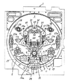
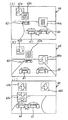
まず、図1を参照して、パチンコ遊技機の遊技盤1の構成について説明する。図1は、遊技盤1を示す正面図である。図1において、遊技盤1の表面には、発射された打玉を誘導するための誘導レール2がほぼ円状に設けられており、その誘導レール2にて区画された領域が遊技領域3となっている。遊技領域3のほぼ中央には、後述するキャラクタ画像表示部60での識別情報(以下、特別図柄という)の可変表示(以下、変動ともいう)を可能にする可変表示装置としての特別可変表示装置30が配設されている。なお、特別可変表示装置30の詳細な構成については後に詳述する。
First, with reference to FIG. 1, the structure of the
特別可変表示装置30の下方には、普通可変入賞球装置5および特別可変入賞球装置9等の各種構成部材を遊技盤1に取付けるための取付基板4が設けられている。取付基板4の中央上端部には、特別図柄の変動を許容する変動機能を有する普通可変入賞球装置5が配設されている。この普通可変入賞球装置5は、ソレノイド6によって垂直(通常開放)位置と傾動(拡大開放)位置との間で可動制御される1対の可動翼片7a,7bを有して、いわゆるチューリップ型役物として構成され、その普通可変入賞球装置5には入賞した打玉を検出する始動玉検出器8が設けられている。なお、可動翼片7a,7bが垂直(通常開放)位置のときも普通可変入賞球装置5に入賞可能になっている。また、普通可変入賞球装置5への入賞に基づく特別図柄の変動は、変動中を除いて所定回数(本実施の形態では4回)記憶され、その旨が後述の特別図柄記憶表示LED36によって表示される。
Below the special
前記取付基板4の中央部には、特別可変入賞球装置9が配設されており、その特別可変入賞球装置9は、入賞領域14を開閉制御する開閉板11を備えている。すなわち、開閉板11は、遊技盤1の裏面に設けられたソレノイド10の駆動に基づいて傾動位置と垂直位置との間で変動自在となっており、ソレノイド10がONされたときには入賞領域14を開放する傾動状態となる一方、ソレノイド10がOFFされたときには入賞領域14を閉鎖する垂直状態となる。また、入賞領域14内には、入賞玉を検出する特定玉検出器12および入賞玉検出器13が設けられている。なお、特定玉検出器12は、入賞玉の検出により後述する継続権の成立を許容するようになっている。
A special variable winning
また、前記特別可変入賞球装置9の下方には、通過玉検出器15を備えた突出部材16が設けられている。なお、突出部材16の左側部には、打玉を通過玉検出器15に通過させるための通過口16aが穿設されている。そして、通過玉検出器15は、通過玉を検出すると後述する普通図柄表示器34に表示される普通図柄の変動を許容するようになっている。なお、普通図柄表示器34は、普通図柄が当り図柄となったときに、普通可変入賞球装置5の可動翼片7a,7bを所定時間が経過するまで開放制御するものであるが、後述する確率変動(大当り判定確率が通常時と異なる高い確率に変更された遊技状態)が生じたときには、開放時間が長くなるように設定されている。また、普通図柄の変動は、変動中を除いて所定回数(本実施の形態では4回)記憶され、その旨が後述する普通図柄記憶表示LED35によって表示されるようになっており、その変動時間は、確率変動時には通常時に比べて短縮されるようになっている。なお、このような普通図柄の変動記憶は常に一定(たとえば4回)に設定する必要はなく、たとえば通常時では1回にする一方では、後述の確率変動中では4回にすることも可能である。また、前記取付基板4の左右両端部には、それぞれ飾りLED17を備えた入賞口18が設けられている。また、前記特別可変入賞球装置9の入賞領域14内壁には、V入賞表示LED19が設けられている。
A projecting
しかして、前述のように構成される特別可変入賞球装置9は、以下のように動作する。すなわち、打玉が普通可変入賞球装置5に入賞して始動玉検出器8をONさせると、特別可変表示装置30が変動を開始し、一定時間が経過すると、たとえば左,右,中の順で特別図柄が確定され、その確定された図柄の組合せが特定表示結果をなす所定の大当り組合せ(同一図柄のぞろ目)となったときに特定遊技状態(大当り遊技状態ともいう)となる。そして、この特定遊技状態においては、特別可変入賞球装置9の開閉板11が所定期間(たとえば29秒)あるいは所定個数(たとえば10個)の入賞玉が発生するまで開放(開放サイクル)するように設定され、その開放している間遊技盤1の表面を落下する打玉を受止めるようになっている。そして、受止められた打玉が特定玉検出器12をONすると、再度前記した開放サイクルを繰返し、特定玉検出器12がONする毎に繰返継続条件が成立して特別可変入賞球装置9を再度開放させる繰返継続制御が実行される。この繰返継続制御の実行条件回数はたとえば16回と定められている。なお、前記各入賞口もしくは各可変入賞球装置内に入った入賞玉は、1個の入賞玉に対し所定数(たとえば15個)の景品玉が払出される。
Thus, the special variable winning
また、遊技領域3を含む遊技盤1の表面には、前記した構成以外にも、風車ランプ20aを内蔵した風車20、左右1対の飾りランプ21a,21b、袖ランプ22aを内蔵した入賞口22、サイドランプ23aを内蔵したサイドランプ飾り23、アウト口24、バック玉防止部材25等が設けられている。また、パチンコ遊技機には、特定遊技状態時あるいは変動時に点灯または点滅してその旨を報知する遊技効果ランプおよび遊技効果LED(ともに図示しない)が設けられているとともに、効果音を発生するスピーカ26(符号のみ図3参照)が設けられている。
Further, on the surface of the
次に、本実施の形態の要部を構成する特別可変表示装置30の構成について説明する。特別可変表示装置30は、前記遊技盤1の表面に取付けられる取付基板31を有し、該取付基板31には、長方形状の窓枠部32が形成されている。そして、この窓枠部32の後方には、後述する左,中,右の各特別図柄を可変表示し得るキャラクタ画像表示部60を有するLCD表示器33が隣接されている。また、窓枠部32の上方には、普通図柄表示器34、普通図柄記憶表示LED35、特別図柄記憶表示LED36、および飾りLED37が設けられ、窓枠部32の左右側方には、各飾りLED38,39が設けられている。一方、窓枠部32の下方には、各飾りLED40,41が設けられている。なお、普通図柄表示器34の普通図柄の変動動作およびこれにかかる各種構成部材の動作については後に詳述する。
Next, the configuration of the special
また、上記LCD表示器33のキャラクタ画像表示部60に表示されている左,中,右の各特別図柄は、図4に示すように、それぞれ「0〜9,F,X,G,P,R」順の15種類から構成されている。これら左,中,右の各図柄には、後述するWCRND L・C・R(図4参照)の各ランダムカウンタが対応して設けられている。大当り図柄の組合せは、図5に示すように、左,中,右の各図柄が同一図柄に揃った組合せであり、この組合せは、WCRND Lのランダムカウンタからの抽出値(乱数)に基づいて決定される。また、大当り図柄のうち「1,3,5,7,9」のいずれかで揃った図柄は、確変図柄を構成して後に詳述する確率変動を発生するようになっている。なお、このような確変図柄は、図柄色が赤色になっている一方、その他の特別図柄は緑色になっている。これにより、大当り時の遊技価値の違い(確変の有無)が遊技者に対し明確に報知できるようになっている。
The left, middle, and right special symbols displayed on the character
以上、特別可変表示装置30を含むパチンコ遊技機の遊技盤1の構成について説明したが、それらの遊技装置は、図2および図3に示す遊技制御回路によって制御される。図2および図3は、遊技制御回路を部構成で示す回路図であり、MPU30aおよび図示しないROM、RAM、入出力回路を含んでいる基本回路42によって制御されている。しかして、基本回路42は、入力回路43を介して通過玉検出器15、始動玉検出器8、特定玉検出器12、および入賞玉検出器13からの検出信号が入力され、アドレスデコード回路44から基本回路42にチップセレクト信号が与えられる。また、電源投入時に初期リセット回路45から基本回路42にリセット信号が与えられ、所定時間毎に定期リセット回路46から基本回路42に定期リセット信号が与えられる。
The configuration of the
一方、基本回路42からは、以下の装置および回路に制御信号が与えられる。すなわち、LCD回路47を介して特別可変表示装置30(図2には、LCD表示装置と記載)に表示制御信号が与えられ、LED回路48を介して普通図柄表示器34、特別図柄記憶表示LED36、普通図柄記憶表示LED35、V入賞表示LED19、および各飾りLED17,37〜41に表示駆動信号が与えられ、ソレノイド回路49を介して各ソレノイド6,10に駆動信号が与えられ、ランプ回路50を介して風車ランプ20a、サイドランプ23a、および袖ランプ22aに表示制御信号が与えられ、音声合成回路51および音量増幅回路52を介してスピーカ26に音声信号が与えられる。また、ランプ回路50からは各種のランプ制御データが出力されることで、上記した構成部材以外のランプを表示制御するようになっている。さらに、基本回路42は、情報出力回路53を介して外部(ホールコンピュータや呼出ランプ等)に有効始動情報、大当り情報、および確率変動情報を出力し、また、賞球個数信号出力回路54を介して外部に各種の賞球個数信号を出力している。なお、上記した装置や回路には、電源回路55から各種の電圧を有する電力が供給されている。また、上記した基本回路42からLCD回路47を介して特別可変表示装置30に送信される表示制御信号は、コマンドブロックフォーマットが9バイトのコマンドデータ(CD0〜CD7,INT)からなり、このコマンドデータは、基本回路42内のMPU42aから特別可変表示装置30内のMPU30aに送信されるようになっている。
On the other hand, the
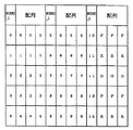
図5は、特定遊技状態(大当り状態)を発生させることが決定された場合に特別可変表示装置30に表示される当り図柄の配列を説明する説明図である。この当り図柄の配列は、後述するように、WCRND Lの抽出値(乱数)に基づいて決定される。たとえば、図示するように、WCRND Lの抽出値が0の場合には左,中,右の各可変表示部に「000」が表示される。またWCRND Lの抽出値が「1」の場合には、「111」が停止表示される。
FIG. 5 is an explanatory diagram for explaining an arrangement of winning symbols displayed on the special
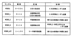
次に、前記特別可変表示装置30による特別図柄の変動動作について図6〜図21に示すタイミングチャートおよび説明図等を参照して説明する。まず、特別可変表示装置30の変動動作に用いられるランダムカウンタについて説明する。特別可変表示装置30では、図6に示すような5種類のランダムカウンタが使用されており、これらのランダムカウンタは大当り決定用のWCRND1と、左図柄表示用でありかつ大当り表示用のWCRND Lと、中図柄表示用のWCRND Cと、右図柄表示用のWCRND Rと、リーチ動作表示用のWCRNDACTと、から構成されている。
Next, the special symbol changing operation by the special
前述した基本回路42のMPU42aは、2msec毎に入力される定期リセット信号(定期リセット回路46からの信号)の入力毎にROM100に記憶されているプログラムを初めから最後まで実行し、実行し終わった後次の定期リセット信号が入力されてくるのを待ち、入力されてきた段階で再度プログラムを初めから実行するのである。そして、このWCRND1は、MPU42aがプログラムを実行する毎すなわち0.002秒毎に1ずつ加算処理されるものであり、0から加算されてその上限である224まで加算された後再度0から加算される。
The
WCRND Lも、同様に0.002秒毎に1ずつ加算されて0から加算されてその上限である14まで加算された後再度0から加算される。WCRND Cは、MPU42aがプログラムを一通り実行し終わって次の定期リセット信号の入力を待っている割込処理余り時間に無限ループにより加算処理がなされるのである。そして0から加算されてその上限である14まで加算された後再度0から加算される。
Similarly, WCRND L is also incremented by 1 every 0.002 seconds, is incremented from 0, is incremented to 14 which is the upper limit thereof, and is incremented from 0 again. In WCRND C, addition processing is performed by an infinite loop during the interruption processing surplus time waiting for the input of the next periodic reset signal after the
WCRND Rは、前記WCRND Cの桁上げのとき1ずつ加算される。すなわち、WCRND Cがその上限である14まで加算された状態でさらに「1」加算されるごとにWCRND Rが1ずつ加算される。そして0から加算されてその上限である14まで加算された後再度0から加算される。WCRND ACTは、前記WCRND Cと同様に割込処理余り時間に無限ループにより加算され、1から加算されてその上限である100まで加算された後再度1から加算される。このWCRND ACTは、リーチ動作の種類を決定するために用いられる。 WCRND R is incremented by 1 when the carry of WCRND C is carried out. That is, WCRND R is incremented by 1 each time “1” is incremented while WCRND C is incremented to 14. Then, it is added from 0 and added up to 14 which is the upper limit, and then added again from 0. As with WCRND C, WCRND ACT is added to the interrupt processing surplus time by an infinite loop, is added from 1, is added to 100, which is the upper limit thereof, and is added again from 1. This WCRND ACT is used to determine the type of reach operation.
そして、図7に示すように、WCRND1から抽出された値(乱数)が「3」であり大当りと判定されると、WCRND L(0〜14)の抽出値(乱数)により図5に示したように大当り図柄の配列が決定され、この大当り図柄(予定停止図柄)が特別可変表示装置30のLCD表示器33に表示される。一方、WCRND1からの抽出値が「3」以外の場合には外れと判定され、WCRND L,C,Rからの各抽出値に対応する予定停止図柄が事前決定されて外れ図柄として特別可変表示装置30のLCD表示器33に表示される。なお、WCRNDL,C,Rからの各抽出値が偶然にも大当り図柄と一致した場合(ぞろ目となった場合)には、WCRND Rのデータに「1」を加算して強制的に外れ図柄にずらして表示する。なお、このような当り外れの判定において、確率変動時(高確率時)には、WCRND1内の「3,7,67,77,137」の値が大当り決定用の大当り判定値となり、WCRND1の抽出値がこれら大当り判定値のいずれかに該当すれば大当りを発生させることが決定される。
Then, as shown in FIG. 7, when the value (random number) extracted from WCRND1 is “3” and determined to be a big hit, it is shown in FIG. 5 by the extracted value (random number) of WCRND L (0-14). Thus, the arrangement of the jackpot symbol is determined, and this jackpot symbol (scheduled stop symbol) is displayed on the
特別図柄の変動は図12〜図14のタイミングチャートに示すようになっている。なお、左,中,右の各図柄列の変動は、図8の一覧表に示すパターンに基づいて行なわれる。変動パターンAは、一定の速度で変動(16.7msecに1図柄変動)するパターンであり、変動パターンBは、徐々に減速して停止するパターンであり、変動パターンCは、徐々に減速するパターンであり、変動パターンDは、一定の速度で変動(333.3msecに1図柄変動、1周期5.000秒)するパターンであり、変動パターンEは、徐々に減速して停止(1図柄変動)するパターンであり、変動パターンGは、一定速度の後減速して停止するパターンである。また、図12〜図14の各タイムチャートの中に記載の条件1〜3、および※1〜※5は、図9〜図11の各一覧表図に示すものである。なお、※2は、ショートスベリ変動制御を行なった場合の変動時間であり、※3は、ミドルスベリ変動制御を行なった場合の変動時間であり、※4は、ロングスベリ変動制御を行なった場合の変動時間である。また、※5は、後述する各リーチ1〜3の選択条件であり、各条件1〜3および前記WCRND ACTの抽出値に基づいて外れおよび大当り毎に決定される。また、スベリ変動(これをスベリという)とは、最終停止図柄以外の図柄に対する特殊変動のことであり、通常の変動制御に比べて図柄変動量の多い変動制御のことをいう。
The variation of the special symbol is as shown in the timing charts of FIGS. Note that the variation of the left, middle, and right symbol sequences is performed based on the patterns shown in the list of FIG. The fluctuation pattern A is a pattern that fluctuates at a constant speed (one symbol fluctuation in 16.7 msec), the fluctuation pattern B is a pattern that gradually decelerates and stops, and the fluctuation pattern C is a pattern that gradually decelerates. Fluctuation pattern D is a pattern that fluctuates at a constant speed (one symbol variation at 333.3 msec, one cycle is 5.000 seconds), and variation pattern E is gradually decelerated and stopped (one symbol variation) The fluctuation pattern G is a pattern that decelerates and stops after a constant speed. Further,
まず、図12において、普通可変入賞球装置5に打玉が入賞し始動玉検出器8が始動信号を出力すると、その始動信号の立上がり時にWCRND1から数値を抽出してこれを格納する。その後、始動信号の立上がりより0.002秒後には、WCRND L,C,RおよびWCRND ACTから数値を抽出するとともに、格納したWCRND1の読出および判定を行なう。そして始動信号の立上がりより0.004秒後に、左,中,右の全図柄列を変動パターンAにして変動させる。その後、左図柄列は、6.260秒変動パターンAにて変動された後に、予定停止図柄の3図柄手前がセットされ、そこから0.420秒間変動パターンBにて変動する。このような制御を飛ばし制御という。そして停止する。右図柄列については、スベリ変動がない場合には、6.680秒間変動パターンAにて変動された後、停止図柄の3図柄前がセットされ、そこから0.420秒間変動パターンBにて3図柄分変動されて停止する。このような制御を飛ばし制御という。右図柄列については、スベリ変動がない場合は、6.680秒間変動パターンAにて変動された後、予定停止図柄の3図柄手前がセットされて、そこから0.420秒間変動パターンBにて3図柄分変動されて丁度予定停止図柄で停止する。また、ショートスベリがある場合は、6.680秒間変動パターンAにて変動された後、予定停止図柄の4〜7図柄前がセットされて前記※2の0.560〜0.980秒間変動パターンBにて4〜7図柄のいずれかの図柄分変動されて停止する。ミドルスベリがある場合は、図13に示すように、6.680秒間変動パターンAにて変動された後、予定停止図柄の8〜15図柄前がセットされて前記※3の1.120〜2.100秒間変動パターンBにて8〜15図柄のいずれかの図柄分変動されて停止する。ロングスベリがある場合は、6.680秒間変動パターンAにて変動された後、予定停止図柄の16〜21図柄手前がセットされて前記※4の2.240〜2.940秒間変動パターンBにて16〜21図柄のいずれかの図柄分変動されて停止する。また、一旦停止でショートスベリがある場合は、6.680秒間変動パターンAにて変動された後に予定停止図柄の4〜7図柄手前がセットされて0.480秒間一時停止されてその後0.560〜0.980秒間変動パターンGにて4〜7図柄のいずれかの図柄分変動されて停止する。
First, in FIG. 12, when a hit ball is won in the normal variable winning
一方、中図柄は、図14に示すように、リーチ以外のときには、7.100〜9.620秒間変動パターンAにて変動した後、中図柄についての予定停止図柄の3図柄手前がセットされ、そこから変動パターンBにて変動が開始されて0.850秒(3図柄分変動する時間)変動した後に停止される。これにより、丁度予定停止図柄で停止表示される。 On the other hand, as shown in FIG. 14, when the middle symbol is other than the reach, after the variation in the variation pattern A for 7.100 to 9.620 seconds, 3 symbols before the scheduled stop symbol for the middle symbol are set, From there, the fluctuation is started in the fluctuation pattern B and stopped after fluctuation for 0.850 seconds (time for fluctuation for three symbols). As a result, the stop display is performed with exactly the scheduled stop symbol.
リーチ1での中図柄は、変動パターンAで7.100〜9.620秒間変動した後に、リーチ図柄の4図柄手前がセットされる。リーチが成立している場合には常に停止表示されている右図柄と左図柄とが同じ種類のぞろ目の図柄になってるのであり、そのぞろ目の同じ種類の図柄をリーチ図柄という。ゆえに、この中図柄がそのリーチ図柄で停止表示されれば、特定遊技状態(大当り状態)が発生することになる。そして変動パターンAが終了した後にリーチ図柄の4図柄手前がセットされた状態で変動パターンCが開始されて0.420秒(3図柄変動する時間)変動して、変動パターンDが開始される。ゆえに、リーチ図柄の1図柄手前からこの変動パターンDが開始されることとなる。この変動パターンDは、5.664〜10.340秒(17〜31図柄分変動する時間)継続される。この変動パターンDは、後述する図21,図22に基づいてR1TBLのテーブルから読出されたリーチ動作時間であり、+0図柄〜+14図柄の15種類のリーチ動作時間の中から或る1つのリーチ動作時間が選択され、その選択されたリーチ動作時間だけ変動パターンDが実行される。すなわち、前記R1TBLのテーブルは、17〜31図柄分の変動時間である15種類のリーチ動作時間を記憶している。そしてこの変動パターンDが終了した後に変動パターンEが1.184秒(1図柄分変動する時間)実行され、1図柄分変動制御された後に停止制御される。これにより、中図柄の予定停止図柄で停止表示されることとなる。
The middle symbol in
リーチ2の場合には、変動パターンAが7.100〜9.620秒実行された段階でリーチ図柄の4図柄手前がセットされて、そこから変動パターンCが開示されて0.420秒だけ変動して3図柄分変動される。その状態で、リーチ図柄の1図柄手前が表示されている状態となる。その状態で変動パターンDが開始されて10.340秒実行され31図柄分変動される。中図柄は前述したように0〜14の図柄番号からなる15種類の図柄が存在するために、変動パターンDにより31図柄変動すれば丁度中図柄が2回転+1図柄分変動することとなる。その結果、変動パターンDが終了した段階で大当り図柄が表示されている状態となる。その後、0.400秒間の停止と0.200秒間の1図柄変動とからなるコマ送り変動が0.600〜9.000秒間(1〜15図柄変動分)行なわれて停止表示される。このコマ送り変動の時間は、後述の図21に示すR2TBLのテーブルをルックアップして読出されたリーチ動作時間である。ゆえに、R2TBLのテーブルには、1〜15図柄分の変動時間すなわち15種類のリーチ変動時間が記憶されている。リーチ3の場合には、変動パターンAが7.100〜9.620秒間実行されてリーチ図柄の4図柄手前がセットされる。そして変動パターンCが0.420秒実行されて3図柄変動した状態でリーチ図柄の1図柄手前が表示されることとなる。その状態で変動パターンDが開始されて10.340秒実行されて31図柄変動し、ショートリーチ図柄が表示される状態となる。その状態で一旦0.400秒間停止された後に0.167または2.338または2.505秒間変動パターンAにて変動されて1または14または15図柄分の変動がなされて停止表示される。この変動パターンAの変動時間は、後述する図21のR3TBLのテーブルをルックアップして読出されたリーチ動作時間である。このリーチ3が実行されて中図柄が停止される場合には、その中図柄の停止図柄は、リーチ図柄で停止表示される場合とリーチ図柄の1つ手前の図柄で停止表示される場合とリーチ図柄の1つ次の図柄で停止表示される場合との3種類しかない。ゆえに、R3TBLのテーブルには、その3種類のリーチ動作時間が記憶されている。
In the case of
ところで、前述したように本実施の形態では、図柄のスベリ変動を右図柄に対してのみ実施可能としているが、これに限らず左図柄に対してスベリ変動を可能制御としてもよい。この場合では、図12に示すように、普通可変入賞球装置5に打玉が入賞し始動玉検出器8が始動信号を導出すると、その始動信号の立上がり時にWCRND1から数値を抽出してこれを格納する。その後、始動信号の立上がりより0.002秒後には、WCRNDL,C,RおよびWCRND ACTから数値を抽出するとともに、格納したWCRND1の読出および判定を行なう。そして、始動信号の立上がりより0.004秒後に、左,中,右の全図柄列を変動パターンAにて変動させる(図12中には、左図柄のみを記載)。その後、左図柄列について、スベリがない場合は、6.260秒間変動パターンAにて変動された後、予定停止図柄の3図柄手前がセットされて、そこから0.420秒間変動パターンBにて3図柄分変動させて丁度予定停止図柄で停止させる。また、ショートスベリがある場合は、6.260秒間変動パターンAにて変動させた後、停止図柄の4〜7図柄手前がセットされて0.560〜0.980秒間変動パターンBにて4〜7図柄のいずれかの図柄分変動されて停止する。
By the way, as described above, in the present embodiment, the design variation of the symbol can be performed only for the right symbol. However, the present invention is not limited to this, and it may be possible to control the variation of the symbol for the left symbol. In this case, as shown in FIG. 12, when a hitting ball wins the normal variable winning
また、一旦停止でショートスベリがある場合は、6.260秒間変動パターンAにて変動された後に停止図柄の4〜7図柄手前がセットされて0.480秒間一時停止され、その後0.560〜0.980秒間変動パターンGにて4〜7図柄のいずれかの図柄分変動されて停止する。なお、図15中には、ショートスベリがある場合と一旦停止でショートスベリがある場合とを示しているが、前記図12および図13に示すショートスベリ、ミドルスベリ、ロングスベリ、および一旦停止でショートスベリの各スベリ変動制御を左図柄に対して実行してもよい。また、このような左図柄のスベリ変動制御に対する中,右の各図柄の変動制御、図12および図13に示す制御を同様な組合せで適用することができる。具体的には、左,右の各図柄に対してスベリ変動制御の実施を可能としたり、あるいは右図柄に対してのみスベリ変動制御の実施を可能としてもよい。なお、本実施の形態では、識別情報を左,中,右の3図柄から構成するとともに、左図柄,右図柄,中図柄の順で停止表示するようになっているため、最終停止図柄(中図柄)以外の左,右の各図柄に対してスベリ変動制御を行なうものとしているが、特にこのような図柄数および停止順序については限定するものではなく、少なくとも最終停止図柄以外の図柄に対してスベリ変動制御を行なうものであればよい。 Also, if there is a short slip due to a stop, after changing in the fluctuation pattern A for 6.260 seconds, 4-7 symbols before the stop symbol is set and paused for 0.480 seconds, and then 0.560- It is changed by any of the 4 to 7 symbols in the variation pattern G for 0.980 seconds and stops. FIG. 15 shows a case where there is a short slide and a case where there is a short slide once stopped, but a short slide, a middle slide, a long sleeve and a short stop shown in FIGS. Each slip variation control of slip may be executed for the left symbol. In addition, the middle and right symbol variation control and the control shown in FIGS. 12 and 13 can be applied in a similar combination to the left symbol slip variation control. Specifically, the slip variation control may be performed on the left and right symbols, or the slip variation control may be performed only on the right symbol. In this embodiment, the identification information is composed of three symbols, left, middle, and right, and the stop symbol is displayed in the order of left symbol, right symbol, and middle symbol. Sliding variation control is performed for each of the left and right symbols other than (symbol). However, the number of symbols and the stop order are not particularly limited, and at least for symbols other than the final stop symbol. Any device that performs slip fluctuation control may be used.
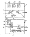
次に、キャラクタ画像表示部60に表示される具体的な図柄変動画像について図15〜図18を参照して説明する。なお、本実施の形態では、「カーレース」をゲームコンセプトに採用することで、キャラクタ画像表示部60に表示するキャラクタ画像もこれに基づいたものとなっている。すなわち、図15(A)に示すように、レーシングカー61が遊技者用のキャラクタ画像となる一方で、レーシングカー61の前方に表示される3台のレーシングカー62〜64が相手方のキャラクタ画像となり、これら4台のレーシングカー61〜64が表示画像上であたかもカーレースを行なうような表示となっている。また、レーシングカー62〜64上には、それぞれ左,中,右の各特別図柄表示部(可変表示部)62a,63a,64aが設けられており、これら特別図柄表示部62a,63a,64aでは、それぞれ左,中,右の各特別図柄が可変表示されるようになっている。そして、図15(B)に示すように、各特別図柄表示部62a,63a,64aで図柄変動が行なわれている中、レーシングカー61がまず左側のレーシングカー62に体当りする。これにより、左特別図柄表示部62aの変動が停止するとともに、この変動停止した左図柄が表示画面の上部左側に左確定図柄62bとして表示される(図15(C)参照)。その後は、同様にしてレーシングカー61が右側および中側の各レーシングカー64,63に順次体当りすることで、左,中の各図柄が表示画面の上部右側および上部中央に左,中の各確定図柄64b,63bとして表示される(図16(A)参照)。なお、図16(A)は、リーチせずに外れが確定した場合の表示画像である。
Next, a specific symbol variation image displayed on the character
次に、右図柄のスベリ変動の有無における各リーチ変動でのキャラクタ画像の表示を説明する。まず、右図柄のスベリ変動がない場合では図16(B)に示すように、前述したリーチしない場合と同様の各図柄変動を行なう中で、レーシングカー61が右側のレーシングカー64に体当りする時点で右側特別図柄表示部64aの表示図柄が既に確定した左確定図柄62bと同一のときに、左,右の各確定図柄62b,64bが同一に揃ってリーチとなる。これに対して、右図柄のスベリ変動がある場合には、図17(A)に示すように、左確定図柄62bの確定後にレーシングカー61が右側のレーシングカー64に体当りすると、この時点から右特別図柄変動部64aで右図柄のスベリ変動が開始され、所定時間後に右特別図柄表示部64aが左確定図柄62bと同一の図柄で停止されてリーチとなる(図17(B)参照)。その後は、前述した右図柄のスベリ変動の有無にかかわらず図17(C)に示すような左,右の各確定図柄62b,64bが同一図柄に揃ったリーチ状態において、レーシングカー61が中央のレーシングカー63に体当りして、中特別図柄表示部63aが各確定図柄62b,64bと同一図柄にて停止されると、図18に示すように、「大当り」の文字65が表示されて大当りが確定される。
Next, the display of the character image at each reach variation in the presence or absence of the variation in the right pattern will be described. First, when there is no slip variation of the right symbol, as shown in FIG. 16B, the time when the
なお、本発明でいうリーチ状態とは、表示状態が変化可能な可変表示装置を有し、該可変表示装置が時期を異ならせて複数の表示結果を導出表示し、該複数の表示結果が予め定められた特定の表示態様の組合せとなった場合に、遊技状態が遊技者にとって有利な特定遊技状態となる遊技機において、前記複数の表示結果の一部がまだ導出表示されていない段階で、既に導出表示されている表示結果が前記特定の表示態様の組合せとなる条件を満たしている表示状態をいう。また、別の表現をすれば、リーチ状態とは、表示状態が変化可能な可変表示部を複数有する可変表示装置の表示結果が予め定められた特定の表示態様の組合せになった場合に、遊技状態が遊技者にとって有利な特定遊技状態となる遊技機において、前記可変表示装置の表示結果がまだ導出表示されていない段階で、前記特定の表示態様の組合せが表示されやすい可変表示態様になったと遊技者に思わせるための表示状態をいう。そして、たとえば、前記特定の表示態様の組合せが揃った状態を維持しながら複数の前記可変表示部による可変表示を行なう状態もリーチ表示状態に含まれる。 The reach state referred to in the present invention includes a variable display device whose display state can be changed, and the variable display device derives and displays a plurality of display results at different times, and the plurality of display results are preliminarily displayed. In a gaming machine in which the gaming state becomes a specific gaming state advantageous to the player when the combination of the specific display modes is determined, a part of the plurality of display results is not yet derived and displayed. A display state in which a display result that has already been derived and displayed satisfies a condition that is a combination of the specific display modes. In other words, the reach state is a game in which a display result of a variable display device having a plurality of variable display units whose display states can be changed is a combination of predetermined specific display modes. In a gaming machine in which the state is a specific gaming state advantageous for the player, the combination of the specific display modes is easily displayed at the stage where the display result of the variable display device has not yet been derived and displayed. A display state that makes a player think. For example, a state in which variable display by the plurality of variable display units is performed while maintaining a state where the combinations of the specific display modes are aligned is also included in the reach display state.
図19は、図2に示したROM100内のメモリマップを示す図である。ROM内のアドレスE000H〜FFFFHの記憶領域には、図示するような種々の記憶エリアに分かれている。まずE000H〜E0FFHの記憶領域は、プログラム管理エリアに割振られており、E100H〜E1FFHの記憶領域はROMコメントエリアに割振られており、E200H〜EAD6Hの記憶領域は後述するテーブル1,テーブル2…テーブルnの各種テーブルデータが記憶されるデータ領域となっている。さらにEAD7H〜EDFFHの記憶領域は未使用のエリアとなっている。またEE00H〜F7FFHの記憶領域は、モジュール1,モジュール2,…モジュールnの各プログラムモジュールが記憶されているプログラム領域となっている。F800H〜FFBFHの記憶領域は未使用エリアとなっている。FFC0H〜FFFFHの記憶領域は割込ベクタテーブルを記憶するエリアとなっている。
FIG. 19 is a diagram showing a memory map in the
そして、遊技機のROM100の場合には、プログラム領域とデータ領域との記憶容量に制限があり、遊技の制御内容を面白くして興趣を向上させるためには、プログラム領域をいかに節約して面白味のある制御プログラムを記憶させるかに依存してくる。そこで、本実施の形態では、後述するように、プログラムをモジュール化し、複数のデータテーブルを最小限のモジュール数で扱うことによってプログラム領域の効率を向上させた。
In the case of the
図20は、プログラムモジュールとデータテーブルとの関係を示す説明図である。図20に記憶されているテーブル1,テーブル2,…テーブルnは、すべてプログラム領域に記憶されている1つのプログラムモジュールによって参照できるように構成されている。その結果、プログラム領域のテーブルルックアップのためのプログラムモジュールを少なくすることができ、余ったプログラム領域を有効利用して種々の面白味のある制御プログラムを記憶させることが可能となる。 FIG. 20 is an explanatory diagram showing the relationship between a program module and a data table. 20 are configured so that they can be referred to by one program module stored in the program area. As a result, the number of program modules for table lookup in the program area can be reduced, and various interesting control programs can be stored by effectively using the remaining program area.
図21〜図24は、可変表示装置のリーチ動作制御を行なうためのテーブルおよび制御用フローチャートを示している。 21 to 24 show tables and control flowcharts for performing reach operation control of the variable display device.
まず図23を参照して、図23の(A),(B)はリーチアドレステーブルであり、図23の(C)は各リーチフラグテーブルを示している。リーチアドレステーブルは、図23(C)に示した各リーチフラグテーブルの先頭アドレスデータを記憶しているテーブルである。リーチアドレステーブルは、遊技状態が前述した低確率時の場合にルックアップされるRCATBNと前述した高確率時にルックアップされるRCATBHとの2種類がある。 First, referring to FIG. 23, (A) and (B) in FIG. 23 are reach address tables, and (C) in FIG. 23 shows each reach flag table. The reach address table is a table that stores the top address data of each reach flag table shown in FIG. There are two types of reach address tables: RCATBN that is looked up when the gaming state is at the low probability described above and RCATBH that is looked up at the high probability described above.
低確率時用のRCATBNは、外れ用すなわち特定遊技状態(大当り状態)が発生しない場合にルックアップされるテーブルであるRCTBL1の先頭アドレスデータと、大当りが発生する場合にルックアップされるテーブルであるRCTBL2の先頭アドレスとが記憶されている。 The RCATBN for low probability is a table that is looked up when a big hit occurs, and the head address data of RCTBL1, which is a table that is looked up when a specific gaming state (big hit state) does not occur. The head address of RCTBL2 is stored.
高確率時用のRCATBHは、高確率時における1回目の確率変動時のときの外れ時にルックアップされるテーブルであるRCTBL3の先頭アドレスと、1回目の確率変動時において大当りが発生するときにルックアップされるテーブルであるRCTBL4の先頭アドレスと、2回目の確率変動時における外れとなる場合にルックアップされるテーブルであるRCTBL3の先頭アドレスと、2回目の確率変動時における大当りが発生する場合にルックアップされるテーブルであるRCTBL4の先頭アドレスとが記憶されている。 RCATBH for high probability is looked up when a big hit occurs at the start address of RCTBL3, which is a table looked up at the time of deviation at the time of the first probability change at the time of high probability, and at the time of the first probability change. When the leading address of RCTBL4, which is the table to be uploaded, and the leading address of RCTBL3, which is the table to be looked up when there is a divergence at the time of the second probability change, and when the big hit occurs at the second time of the probability change The head address of RCTBL4 which is a table to be looked up is stored.
図23(C)は、RCTBL1〜RCTBL4の各リーチフラグテーブルを示しており、リーチ用ランダム上限値,リーチフラグ,スベリあり/なし,スベリ動作用テーブルが1単位のレコードとなっており、この1単位のレコードが複数記憶されている。リーチ用ランダム上限値は、図6に示したWCRND ACTのランダムカウンタの抽出値(乱数)に基づいてどの1単位レコードをルックアップするかを決めるための境界値である。WCRND ACTの抽出値がリーチ用ランダム上限値の範囲内となっているところの1単位レコードが選択される。すなわち、RCTBL1〜RCTBL4の各リーチフラグテーブルのうちどのリーチフラグテーブルを参照するかは、図24(A),(B)のリーチアドレステーブルをルックアップして決定され、決定されたリーチフラグテーブルに記憶されている複数の1単位レコードのうちどの1単位レコードを選択するかは、前述のWCRND ACTの抽出値とリーチ用ランダム上限値とで決定される。 FIG. 23C shows the reach flag tables of RCTBL1 to RCTBL4. The reach random upper limit value, the reach flag, with / without slip, and the slip operation table are records of one unit. Multiple unit records are stored. The reach random upper limit value is a boundary value for determining which one unit record is to be looked up based on the extracted value (random number) of the random counter of WCRND ACT shown in FIG. One unit record where the extracted value of WCRND ACT is within the range of the reach random upper limit value is selected. That is, which reach flag table is referred to among the reach flag tables RCTBL1 to RCTBL4 is determined by looking up the reach address table shown in FIGS. 24A and 24B, and the determined reach flag table is stored in the reach flag table. Which one unit record is selected from the plurality of stored one unit records is determined by the extracted value of WCRND ACT and the reach random upper limit value.
リーチフラグとは、リーチの種類を決定するためのフラグである。スベリあり/なしは、図12,図13で説明したスベリ動作の有無を決定するためのデータである。スベリ動作用テーブルとは、スベリの種類とその動作時間をレコードとして記憶しているテーブルのアドレスデータである。 The reach flag is a flag for determining the type of reach. “With / without slip” is data for determining the presence or absence of the slip operation described with reference to FIGS. The sliding operation table is address data of a table that stores the type of sliding and its operation time as a record.
前述したリーチフラグによりリーチの種類を決定する具体的方法とし、図11を参照して説明する。まず大当りが発生する場合と大当りがしない外れの場合とで大きく場合分けされる。外れの場合には、図9に示す条件1,条件2,条件3の3つの条件でさらに場合分けされる。条件1とは、リーチで、大当り図柄の1図柄手前で中図柄が停止する場合であり、条件2とは、リーチで、大当り図柄の1図柄後で中図柄が停止する場合であり、条件3とは、リーチで、大当り図柄の前後以外で中図柄が停止する場合である。
A specific method for determining the type of reach based on the reach flag described above will be described with reference to FIG. First of all, there are two cases: a case where a big hit occurs and a case where a big hit does not occur. In the case of divergence, the cases are further divided into three conditions,
そして、外れの場合において、条件1の場合でかつWCRND ACTの抽出値が1〜25の範囲内である場合にはリーチ1が選択され、条件2でかつWCRND ACTの抽出値が1〜25の場合にリーチ1が選択され、条件3でかつWCRND ACTが1〜75の範囲内である場合にリーチ1が選択される。
In the case of divergence, reach 1 is selected in the case of
リーチ2は、条件1でかつWCRND ACTの抽出値が26〜50の範囲内である場合、条件2でかつWCRND ACTの抽出値が26〜50の範囲内である場合、条件3でかつWCRND ACTの抽出値が76〜100の範囲内である場合に選択される。リーチ3は、条件1でかつWCRND ACTの抽出値が51〜100の範囲内である場合、条件2でかつWCRND ACTの抽出値が51〜100の範囲内である場合に選択される。
一方、大当りが発生する場合には、WCRND ACTの抽出値が1〜25の範囲内である場合にリーチ1が選択され、26〜50の範囲内である場合にリーチ2が選択され、51〜100の範囲内である場合にリーチ3が選択される。 On the other hand, when a big hit occurs, reach 1 is selected when the extracted value of WCRND ACT is within a range of 1 to 25, and reach 2 is selected when it is within a range of 26 to 50. If it is within the range of 100, reach 3 is selected.
以上説明したリーチ1〜リーチ3の選択が、後述する図22のS1により行なわれる。そして、リーチの種類が決定されれば、図21に示すリーチ動作時間テーブルR1TBL〜R3TBLのうち決定されたリーチの種類に相当するテーブルが選択される。そして、その選択されたリーチ動作時間テーブルに記憶されているリーチ動作時間が選択されてそのリーチ動作時間に従って図14に示したリーチ動作制御が行なわれる。
The selection of
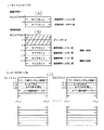
リーチ1が選択された場合にはリーチ動作時間テーブルR1TBLが選択され、リーチ2が選択された場合にはリーチ動作時間テーブルR2TBLが選択され、リーチ3が選択された場合にはリーチ動作時間テーブルR3TBLが選択される。そして各リーチ動作時間テーブルは、図14で説明したリーチ図柄(停止表示されれば大当りとなる図柄)から中図柄の予定停止図柄が何図柄変位しているかに応じてそれぞれのリーチ動作時間を記憶している。たとえばリーチ図柄そのものが中図柄の予定停止図柄になっている場合(+0図柄の場合)にはその場合のリーチ動作時間をオフセットアドレス0,1に記憶している。また中図柄の予定停止図柄がリーチ図柄から1図柄分変位した図柄(+1図柄)である場合にはオフセットアドレス2,3にそのリーチ動作時間を記憶している。
The reach operation time table R1TBL is selected when
そして、リーチ3が選択された場合のリーチ動作時間テーブルR3TBLは、図14に基づいて説明したように、中図柄の停止図柄が3種類しか存在しない。すなわち、リーチ図柄そのもので停止させる場合とリーチ図柄の次の図柄で停止させる場合とリーチ図柄の14個次の図柄すなわちリーチ図柄の1つ手前の図柄で停止させる場合との3種類である。ゆえに、R3TBLには、その3種類のリーチ動作時間が記憶されている。そして、リーチ図柄そのものが予定停止図柄の場合にはオフセットアドレス0,1にリーチ動作時間を記憶させ、リーチ図柄の次の図柄が予定停止図柄の場合にはオフセットアドレス2,3にリーチ動作時間を記憶させ、リーチ図柄から14図柄変位した図柄が予定停止図柄の場合にはそのリーチ動作時間をオフセットアドレス28,29に記憶させている。その結果、オフセットアドレス4〜27にはリーチ動作時間が何ら記憶されていないことになる。そこで、図21(C)に示すように、オフセットアドレス4〜27に24バイト分のダミーデータを記憶させている。このダミーデータはどのようなデータであってもよいが、通常は、プログラムの仕様変更時の汎用性を考慮して、R1TBL,R2TBLと同様に+2図柄〜+13図柄のリーチ動作時間を記憶させておくのが望ましい。そうすることで、プログラム仕様変更毎にデータテーブルの大きさを変化もしくは新しく設けたりする作業を省くことができる。
In the reach operation time table R3TBL when the
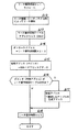
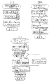
図22は、図21に示したリーチ動作時間テーブルをルックアップするためのプログラムを示すフローチャートである。まずS1により、リーチフラグ(図23(C)参照)の内容によってリーチの種類を選択する処理がなされる。これは、図11に基づいて既に詳述している。次にS2に進み、S1により選択されたリーチの種類に対応するリーチ動作時間テーブルの先頭アドレス(Addr)を決定する処理がなされる。次にS3に進み、S2により選択されたリーチ動作時間テーブルのオフセットアドレスを、リーチ動作図柄数×2によって算出する処理がなされる。全中図柄数は前述したように15図柄あり、それぞれ0〜14の通し番号が付されており、ここでいう「リーチ動作図柄数」は、中図柄の予定停止図柄番号と前述したリーチ図柄番号との差である。次にS4に進み、有効アドレス=Addr+オフセットアドレス の算出を行なう。そしてS5に進み、S4により算出された有効アドレスに記憶されているリーチ動作時間を読出してセットする処理がなされる。 FIG. 22 is a flowchart showing a program for looking up the reach operation time table shown in FIG. First, in S1, processing for selecting the type of reach according to the contents of the reach flag (see FIG. 23C) is performed. This has already been described in detail with reference to FIG. Next, the process proceeds to S2, and a process for determining the start address (Addr) of the reach operation time table corresponding to the type of reach selected in S1 is performed. Next, the process proceeds to S3, in which the offset address of the reach operation time table selected in S2 is calculated by the number of reach operation symbols × 2. As described above, the total number of symbols is 15 symbols, each of which is assigned a serial number of 0 to 14, and the “reach operation symbol number” here is the planned stop symbol number of the middle symbol and the aforementioned reach symbol number. Is the difference. Next, in S4, effective address = Addr + offset address is calculated. Then, the process proceeds to S5, where the reach operation time stored in the effective address calculated in S4 is read and set.
このように、図21に示したようにダミーデータを挿入することにより、リーチ動作時間テーブルR1TBL〜R3TBLにおける或るデータテーブル内での同種類のデータの配列位置と他のデータテーブル内での同種類のデータの配列位置とが同じとなるデータ配列構造に構成されているために、リーチ動作時間テーブルの先頭アドレスを指定するだけで、後は1本のオフセットアドレスを算出する式(S3参照)ですべてのリーチ動作時間テーブル内のレコードを参照することが可能となる。つまり、1つのプログラムモジュール(図22)で全てのリーチ動作時間テーブルR1TBL〜R3TBL内のレコードを参照することができ、プログラム領域を節約できる。そして、リーチ動作時間テーブルR3TBLに関しては、+0図柄と+1図柄と+14図柄との3種類の図柄しか選択されないために、24バイトのダミーデータの領域をプログラムが参照することはない。 Thus, by inserting dummy data as shown in FIG. 21, the arrangement position of the same type of data in a certain data table in the reach operation time tables R1TBL to R3TBL and the same in other data tables. Since the data arrangement structure is the same as the arrangement position of the types of data, only the start address of the reach operation time table is specified, and thereafter, an expression for calculating one offset address (see S3). It is possible to refer to the records in all reach operation time tables. That is, the records in all reach operation time tables R1TBL to R3TBL can be referred to by one program module (FIG. 22), and the program area can be saved. With respect to the reach operation time table R3TBL, since only three kinds of symbols of +0 symbol, +1 symbol, and +14 symbol are selected, the program does not refer to the 24-byte dummy data area.
図23(A),(B)に示したリーチアドレステーブルは、高確率用のリーチアドレステーブルRCATBHのオフセットアドレス+0〜+3の領域にダミーデータが記憶されている。そしてこのリーチアドレステーブルをルックアップするプログラムを示したフローチャートが図24に示されている。 In the reach address table shown in FIGS. 23A and 23B, dummy data is stored in the area of the offset address +0 to +3 of the reach address table RCATBH for high probability. FIG. 24 is a flowchart showing a program for looking up the reach address table.
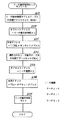
図24を参照して、S6により、確率変動フラグがセットされているか否かの判断がなされる。遊技状態を高確率状態にする場合には確率変動フラグは「1」にセットされており、S6により確率変動フラグ=0と判断された場合には高確率状態ではなく低確率状態であるために、S7に進み、低確率用リーチアドレステーブルであるRCATBNの先頭アドレスがセットされる。一方、確率変動フラグ≠0と判断された場合にはS8に進み、高確率用リーチアドレステーブルであるRCATBHの先頭アドレスがセットされる。 Referring to FIG. 24, in S6, it is determined whether or not the probability variation flag is set. When the gaming state is set to the high probability state, the probability variation flag is set to “1”, and when the probability variation flag = 0 is determined by S6, it is not the high probability state but the low probability state. In S7, the leading address of RCATBN, which is a low probability reach address table, is set. On the other hand, if it is determined that the probability variation flag ≠ 0, the process proceeds to S8, and the head address of RCATBH which is a high probability reach address table is set.
次にS9に進み、オフセットアドレス=確変回数×4+大当りフラグ×2 の算出がなされる。この確変回数は、通常時すなわち低確率時には「0」となっており、高確率時において1回目の確率変動制御がなされている場合には「1」であり、2回目の確率変動制御がなされている場合には「2」となっている。そして大当りフラグは、特定遊技状態(大当り状態)を発生させることが決定された場合には「1」にセットされ、大当りが発生しない場合すなわち外れの場合には「0」となっている。 Next, the process proceeds to S9, where offset address = probable change number × 4 + big hit flag × 2 is calculated. The probability variation number is “0” at normal time, that is, at low probability, and is “1” when the first probability variation control is performed at the high probability, and the second probability variation control is performed. If it is, it is “2”. The big hit flag is set to “1” when it is determined to generate a specific gaming state (big hit state), and is set to “0” when the big hit does not occur, that is, when it is out of play.
次にS10に進み、有効アドレス=先頭アドレス+オフセットアドレス の算出がなされる。たとえば、低確率時でかつ大当りの場合には、先頭アドレスはRCATBNの先頭アドレスとなり、確変回数は「0」、大当りフラグは「1」であるために、代入すれば、有効アドレス=RCATBNの先頭アドレス+0×4+1×2=RCATBNの先頭アドレス+2となる。したがって、図23に示すリーチアドレステーブルRCATBNのRCTBL2が選択される。また、高確率時でかつ確率変動制御が2回目でかつ外れの場合には、先頭アドレスがRCATBHの先頭アドレスであり、確変回数は「2」、大当りフラグは「0」であるために、それらを代入すれば、有効アドレス=RCATBHの先頭アドレス+2×4+0×2=RCATBHの先頭アドレス+8となる。その結果、図23のリーチアドレステーブルRCATBHのオフセットアドレス+8,+9に記憶されているRCTBL3が選択されることとなる。
Next, in S10, the effective address = leading address + offset address is calculated. For example, in the case of a low probability and a big hit, the start address is the start address of RCATBN, the probability variation number is “0”, and the big hit flag is “1”, so if substituted, effective address = the start of RCATBN Address + 0 × 4 + 1 × 2 = Start address of
次にS11に進み、S10より算出された有効アドレスに記憶されているリーチフラグテーブルの先頭アドレス(RCTBL1〜4のいずれか)が選択される。 Next, in S11, the start address (any one of RCTBL1 to 4) of the reach flag table stored in the effective address calculated in S10 is selected.
このように、図23に示す高確率時用のリーチアドレステーブルRCATBHのオフセットアドレス+0〜+3の領域にダミーデータを記憶させているために、1本のオフセットアドレスを求める式(S9参照)により、RCATBN,RCATBHの両テーブルのオフセットを決めることが可能となる。すなわち、RCATBN,RCATBHからなる複数のデータテーブルにおいて、或るデータテーブルと他のデータテーブルとで異なった種類のデータを有する場合には、前記或るデータテーブル内での前記異なった種類のデータの配列位置と前記他のデータテーブル内での前記異なった種類のデータの配列位置とが異なるデータ配列構造に構成されているために、1本のオフセットアドレスを求める式により両テーブルをルックアップすることが可能となる。 In this way, since dummy data is stored in the offset address +0 to +3 area of the reach address table RCATBH for high probability shown in FIG. 23, the equation for obtaining one offset address (see S9) It is possible to determine the offsets of both the RCATBN and RCATBH tables. That is, when a plurality of data tables including RCATBN and RCATBH have different types of data in a certain data table and other data tables, the different types of data in the certain data table are stored. Since both the array position and the array position of the different types of data in the other data table are configured in different data array structures, both tables are looked up by an expression for obtaining one offset address. Is possible.
図25は、リーチ動作時間テーブルの他の例である別実施の形態を示す図である。図25の(A)〜(C)は、図21に示したリーチ動作時間テーブルと同じデータ配列構造のものを示している。これらの各リーチ動作時間テーブルを、図25(D)〜(F)に示すようなデータ配列構造にする。すなわち、R1TBL,R2TBL,R3TBLの3つのリーチ動作時間テーブルの各記憶レコードの中から、共通するレコード(+0図柄,+1図柄,+14図柄のリーチ動作時間)のみを抽出して、それら共通するリーチ動作時間データを同じ配列で各テーブル内に記憶させた。すなわち、図25(D),(E),(F)のように、共通するデータである+14図柄,+0図柄,+1図柄について、+14図柄を1番目に記憶させ、+0図柄を2番目に記憶させ、+1図柄を3番目に記憶させた。 FIG. 25 is a diagram showing another embodiment which is another example of the reach operation time table. 25A to 25C show the same data arrangement structure as the reach operation time table shown in FIG. Each of these reach operation time tables has a data array structure as shown in FIGS. That is, only the common record (reach operation time of +0 symbol, +1 symbol, +14 symbol) is extracted from each storage record of the three reach operation time tables of R1TBL, R2TBL, and R3TBL, and these common reach operations are performed. Time data was stored in each table in the same sequence. That is, as shown in FIGS. 25 (D), (E), and (F), +14 symbols are stored first for +14 symbols, +0 symbols, and +1 symbols that are common data, and +0 symbols are stored second. The +1 symbol was memorized third.
図26は、図25(D)〜(F)に示すリーチ動作時間テーブルをルックアップするプログラムを示すフローチャートである。まずS12により、リーチフラグ(図23(C)参照)の内容からリーチの種類を選択し、S13に進み、その選択されたリーチの種類に対応するリーチ動作時間テーブルの先頭アドレス(Addr)を選択する処理がなされる。次にS14に進み、オフセットアドレス=リーチ動作図柄数×2+2の算出を行なう。ここでいう「リーチ動作図柄数」は、図22で説明したのと同様に、中図柄に関する予定停止図柄番号と中図柄のリーチ図柄番号との差である。 FIG. 26 is a flowchart showing a program for looking up the reach operation time table shown in FIGS. First, in S12, the type of reach is selected from the contents of the reach flag (see FIG. 23C), the process proceeds to S13, and the start address (Addr) of the reach operation time table corresponding to the selected type of reach is selected. Processing is performed. In step S14, the offset address = reach operation symbol number × 2 + 2 is calculated. The “reach operation symbol number” here is the difference between the scheduled stop symbol number for the middle symbol and the reach symbol number for the middle symbol, as described in FIG.
次にS15に進み、有効アドレス(ポインタ)=Addr+オフセットアドレスの算出を行なう。 In step S15, the effective address (pointer) = Addr + offset address is calculated.
次にS16に進み、S15で参照したポインタ(有効アドレス)がリーチ動作時間テーブルの外であるか否かの判断がなされる。そして外でなければS18に進み、S15により算出された有効アドレスに記憶されているリーチ動作時間データを読出してセットする処理がなされる。一方、S16により、ポインタ(有効アドレス)がリーチ動作時間テーブル外であると判断された場合には、S17に進み、有効アドレス=選択したテーブルの先頭アドレスの算出が行なわれる。そしてS18によりその先頭アドレスに記憶されているリーチ動作時間が読出されてセットされる。 Next, in S16, it is determined whether or not the pointer (effective address) referenced in S15 is outside the reach operation time table. If not, the process proceeds to S18, and the reach operation time data stored in the effective address calculated in S15 is read and set. On the other hand, if it is determined in S16 that the pointer (effective address) is outside the reach operation time table, the process proceeds to S17, where the effective address = the head address of the selected table is calculated. In S18, the reach operation time stored in the head address is read and set.
たとえば、中図柄の予定停止図柄がリーチ図柄に対し次の図柄すなわち+1図柄である場合には、リーチ動作図柄数は「1」となるために、オフセットアドレス=1×2+2=4となり、各リーチ動作テーブルR1TBL〜R3TBLにおけるオフセットアドレスが+4のところに記憶されている+1図柄のリーチ動作時間が選択されることとなる。また、中図柄の予定停止図柄がリーチ図柄に対し+14図柄であった場合には、リーチ動作図柄数が「14」となるために、オフセットアドレス=14×2+2=30となる。ところが、R1TBLとR2TBLとは、オフセットアドレスが+0から+29までの領域にリーチ動作時間を記憶しており、R3TBLはオフセットアドレスが+0から+5までの領域にリーチ動作時間を記憶しているために、オフセットアドレスが+30となった場合には、有効アドレス(ポインタ)がS13により選択されたリーチ動作時間テーブルの範囲外となる。その場合には、S16によりYESの判断がなされるS17の処理が行なわれ、S13により選択されたリーチ動作時間テーブルの先頭アドレスすなわち+14図柄のリーチ動作時間が選択されて読出されることとなる。 For example, when the scheduled stop symbol of the middle symbol is the next symbol relative to the reach symbol, that is, +1 symbol, the number of reach operation symbols is “1”, so that the offset address = 1 × 2 + 2 = 4, and each reach The reach operation time of the +1 symbol stored at the position where the offset address in the operation tables R1TBL to R3TBL is +4 is selected. Further, when the scheduled stop symbol of the middle symbol is +14 symbols relative to the reach symbol, the number of reach operation symbols is “14”, so that offset address = 14 × 2 + 2 = 30. However, R1TBL and R2TBL store the reach operation time in the region where the offset address is +0 to +29, and R3TBL stores the reach operation time in the region where the offset address is +0 to +5. When the offset address is +30, the effective address (pointer) is out of the reach operation time table selected in S13. In this case, the process of S17 is performed in which a determination of YES is made in S16, and the leading address of the reach operation time table selected in S13, that is, the reach operation time of +14 symbols is selected and read.
このように、R1TBL〜R3TBLの3つのデータテーブル中で、同種類のレコードはすべてテーブル内においてレコード配列が同じとなるように並べたために、換言すれば、複数のデータテーブル内の或るデータテーブルと他のデータテーブルとで同種類のデータを有する場合には、前記或るデータテーブル内での前記同種類のデータの配列位置と前記他のデータテーブル内での前記同種類のデータの配列位置とが同じとなるデータ配列構造にしたために、複数のデータテーブルの先頭アドレスを指定するだけで、後は、1本のオフセットを求める式で複数のテーブルをルックアップすることが可能となる。なお、図25に示した同種類のデータである+14図柄,+0図柄,+1図柄のリーチ動作時間は、図25の配列に限らず、たとえば、1番最初に+0図柄を配列させ、次に+1図柄を配列させ、3番目に+14図柄を配列させるようにしてもよい。 In this way, in the three data tables R1TBL to R3TBL, all the records of the same type are arranged so that the record arrangement is the same in the table. In other words, a certain data table in a plurality of data tables. And other data tables have the same kind of data, the arrangement position of the same kind of data in the certain data table and the arrangement position of the same kind of data in the other data table Since the data array structures are the same as each other, it is possible to look up the plurality of tables with an expression for obtaining one offset only by designating the top addresses of the plurality of data tables. Note that the reach operation time of the +14 symbol, +0 symbol, and +1 symbol, which are the same type of data shown in FIG. 25, is not limited to the arrangement in FIG. 25, for example, the +0 symbol is arranged first, and then +1 The symbols may be arranged and the +14 symbol may be arranged third.
図27は、リーチ動作時間テーブルのさらに他の例を用いた別実施の形態を示す図である。図27(A)は、図27(B)〜(G)に示す各リーチ動作時間テーブルを選択するためのリーチ動作時間アドレステーブルを示している。リーチ動作時間テーブルは、TBL0〜TBL13の合計14種類あり、それぞれのリーチ動作時間テーブルの先頭アドレスが図27(A)のリーチ動作時間アドレステーブルに記憶されている。 FIG. 27 is a diagram illustrating another embodiment using still another example of the reach operation time table. FIG. 27A shows a reach operation time address table for selecting each reach operation time table shown in FIGS. 27B to 27G. There are a total of 14 reach operation time tables, TBL0 to TBL13, and the start address of each reach operation time table is stored in the reach operation time address table of FIG.
図27(B)〜(G)に示すリーチ動作時間テーブルは、中図柄の予定停止図柄がリーチ図柄とどれだけ変位しているかによって複数設けられている。たとえば、中図柄の予定停止図柄がリーチ図柄そのものである場合すなわち+0図柄である場合には、その場合のリーチ動作時間がリーチ動作時間テーブルTBL0に記憶されている。また中図柄の予定停止図柄がリーチ動作図柄に対して+1図柄である場合には、リーチ動作時間テーブルTBL1にリーチ動作時間が記憶されている。ゆえに、図27(A)に示すリーチ動作時間アドレステーブルは、中図柄の予定停止図柄がリーチ図柄に対しどの程度変位しているかに応じてリーチ動作時間テーブルの先頭アドレスを記憶している。 The reach operation time tables shown in FIGS. 27B to 27G are provided in a plurality depending on how much the planned stop symbol of the middle symbol is displaced from the reach symbol. For example, when the scheduled stop symbol of the middle symbol is the reach symbol itself, that is, when the symbol is +0 symbol, the reach operation time in that case is stored in the reach operation time table TBL0. When the scheduled stop symbol of the middle symbol is +1 symbol with respect to the reach motion symbol, the reach motion time is stored in the reach motion time table TBL1. Therefore, the reach operation time address table shown in FIG. 27A stores the start address of the reach operation time table according to how much the scheduled stop symbol of the middle symbol is displaced with respect to the reach symbol.
一方、リーチ動作時間テーブルの方は、前述したリーチ1,リーチ2,リーチ3の3種類のリーチに応じたリーチ動作時間を記憶している。なお、+0図柄と+1図柄と+14図柄に関してはリーチ動作時間がリーチ1〜リーチ3の3種類存在するために、リーチ動作時間テーブルTBL0,TBL1,TBL14に関しては、リーチ1,リーチ2,リーチ3のそれぞれ3種類のリーチと同じ時間が記憶されている。一方、+2図柄〜+13図柄の場合には、リーチ1の場合とリーチ2の場合しか存在しないために、リーチ動作時間テーブルTBL2〜TBL13に関してはリーチ1,リーチ2の2種類のリーチ動作時間だけが記憶されている。
On the other hand, the reach operation time table stores reach operation times corresponding to the three types of
図28は、図27に示したテーブルをルックアップするためのプログラムを示すフローチャートである。まずS19により、リーチ動作時間アドレステーブルの先頭アドレス(RTBL)がセットされる。次にS20に進み、オフセットアドレス=リーチ動作図柄数×2 が算出される。ここでいう「リーチ動作図柄数」は、前述と同様に、中図柄の予定停止図柄番号とリーチ図柄番号との差である。なおこのS20でいうオフセットアドレスは、リーチ動作時間アドレステーブルRTBLのオフセットアドレスのことである。 FIG. 28 is a flowchart showing a program for looking up the table shown in FIG. First, at S19, the start address (RTBL) of the reach operation time address table is set. In step S20, offset address = reach operation symbol number × 2 is calculated. The “reach motion symbol number” here is the difference between the scheduled symbol number of the middle symbol and the reach symbol number, as described above. The offset address in S20 is an offset address in the reach operation time address table RTBL.
次にS21に進み、有効アドレス=リーチ動作時間アドレステーブルの先頭アドレスRTBL+オフセットアドレスの算出が行なわれる。次にS22に進み、S21により算出された有効アドレスに記憶されているリーチ動作時間テーブルの先頭アドレス(TBLn)をセットする処理がなされる。次にS23に進み、オフセットアドレス=リーチ種類×2の算出が行なわれる。このオフセットアドレスは、リーチ動作時間テーブルTBLn(n=0〜14)のオフセットアドレスである。S23の「リーチ種類」は、リーチ1の場合には0、リーチ2の場合には1、リーチ3の場合には2となる。たとえば、リーチ2の場合にはオフセットアドレス=1×2=2となる。次にS24に進み、リーチ動作時間テーブルの有効アドレス=TBLn+オフセットアドレスの算出が行なわれる。そしてS25に進み、S24により算出された有効アドレスに記憶されているリーチ動作時間が読出されてセットされる。
Next, in S21, the effective address = reach operation time address table start address RTBL + offset address is calculated. Next, the process proceeds to S22, and a process for setting the head address (TBLn) of the reach operation time table stored in the effective address calculated in S21 is performed. Next, in S23, offset address = reach type × 2 is calculated. This offset address is an offset address of the reach operation time table TBLn (n = 0 to 14). The “reach type” in S23 is 0 for
この実施の形態では、リーチ動作時間アドレステーブルとリーチ動作時間テーブルとをそれぞれ1本ずつのアドレス算出式でルックアップ可能である。図25,図26に示した方式の場合には、テーブル内のレコード配列が複雑になると、条件式やアドレス算出式が多くなってプログラム容量が増大する不都合があるが、この図27,図28に示した方式の場合には、条件式やアドレス算出式がそれほど多くなることがなく、プログラム容量の増大化を極力防止することができる。 In this embodiment, the reach operation time address table and the reach operation time table can be looked up with one address calculation formula. In the case of the method shown in FIGS. 25 and 26, if the record arrangement in the table becomes complicated, the conditional expression and the address calculation expression increase and the program capacity increases, but this FIG. 27 and FIG. In the case of the method shown in (1), there are not so many conditional expressions and address calculation expressions, and an increase in program capacity can be prevented as much as possible.
次に、以上説明した実施の形態の特徴や変形例等を以下に列挙する。
(1) 図1において、可変表示装置30は液晶表示装置で構成されたものを示したが、それに代えて、CRTやエレクトロルミネッセンスあるいはプラズマ表示装置を用いたものでもよく、さらには、回転ドラム式のものでもよい。前記特別可変入賞球装置9は、遊技者にとって有利な状態として開閉板11が連続開閉するものであってもよく、また遊技者にとって不利な第2の状態として打玉が入賞可能ではあるが入賞困難な状態であってもよい。また、本発明に係る遊技機は、遊技機全体が画像表示され、たとえば打球操作することにより打玉の画像が表示されてその打玉画像が遊技領域をあたかも自然落下するように表示されるという、いわゆる映像式遊技機であってもよい。
Next, features and modifications of the embodiment described above are listed below.
(1) Although the
図2に示したROMにより、制御用のプログラムが格納されているプログラム格納手段が構成されている。MPU42aにより、前記プログラム格納手段に格納されているプログラムに従って動作する制御中枢手段が構成されている。また基本回路42により、遊技機の遊技状態を制御する遊技制御手段が構成されている。この遊技制御手段は、前記可変表示装置を制御するための指令信号(CD0〜CD7)を出力する。LCD表示装置30のMPU30aにより、前記遊技制御手段から出力された指令信号に従って前記可変表示装置を制御する可変表示制御手段が構成されている。
The ROM shown in FIG. 2 constitutes a program storage means in which a control program is stored. The
図3に示した基本回路42,音声合成回路51,音量増幅回路52により、スピーカ26からなる音発生手段を制御する音制御手段が構成されている。この音制御手段は、遊技状態に応じて前記音発生手段から発生させる音を変化させる制御を行なう。特に、前記可変表示装置の表示状態の変化に応じてその表示状態に応じた音を発生させる制御を行なう機能を有する。たとえば、図14のリーチ1,リーチ2,リーチ3の各リーチの種類に応じてそれぞれ類似する音を発生させるようにしてもよい。そして、この音発生手段を制御する音発生データを、図22〜図28と同様にテーブルの形で記憶してもよい。
The
(2) 図6に示したWCRND1により、特定遊技状態を発生させるか否かをランダムに決定するための乱数を発生させる当り外れ乱数発生手段が構成されている。WCRND Lにより、前記当り外れ乱数発生手段が発生した乱数が特定遊技状態を発生させる乱数値である場合に前記可変表示装置に表示させる表示結果をランダムに決定するための乱数を発生する当り表示結果乱数発生手段が構成されている。WCRND ACTにより、前記リーチ状態を発生させる場合にどのような種類のリーチ状態を発生させるかをランダムに決定するためのリーチ状態乱数発生手段が構成されている。 (2) The WCRND1 shown in FIG. 6 constitutes a hit random number generating means for generating a random number for randomly determining whether or not to generate a specific gaming state. When the random number generated by the hit random number generating means is a random value for generating a specific gaming state by WCRND L, the hit display result for generating a random number for randomly determining the display result to be displayed on the variable display device Random number generating means is configured. The WCRND ACT constitutes reach state random number generating means for randomly determining what kind of reach state is to be generated when the reach state is generated.
図7で説明したように、前記基本回路42からなる遊技制御手段は、前記特定遊技状態の発生確率を変動させる特定遊技状態発生確率変動手段を有している。この特定遊技状態発生確率変動手段は、通常の発生確率からそれよりも高い高確率状態に変化させる機能を有している。
As described with reference to FIG. 7, the game control means including the
(3) 前記ROM100は、図19に示すように、制御用のプログラムを格納するプログラム領域と、制御用のデータを格納するデータ領域とを有している。そして前記プログラム領域には、複数のプログラムモジュールが記憶されている。前記データ領域には、複数のデータテーブルが記憶されている。そして前記複数のプログラムモジュールは、前記複数のデータテーブルをルックアップ(参照)するためのテーブルルックアッププログラムモジュールを有している。なお、プログラムモジュールとは、プログラムのうち独立可能な部分を独立させたものをいう。
(3) As shown in FIG. 19, the
図14で説明したように、前記遊技制御手段と可変表示制御手段は、予め定められた複数種類のリーチ状態の中から所定のリーチ状態を選択して当該選択されたリーチ状態を前記可変表示装置に表示させるリーチ制御手段を有する。このリーチ制御手段は、前記リーチ状態乱数発生手段が発生した乱数に従って前記複数種類のリーチの中から所定のリーチを選択する機能を有する。前記複数種類のリーチは、それぞれ、複数のリーチ動作時間の中から選択されたリーチ動作時間だけリーチ動作する。すなわち、前記複数種類のリーチそれぞれに、複数種類のリーチ動作時間が割振られており、前記リーチ制御手段が前記複数種類のリーチのうちからどのリーチを選択したかに応じて、その選択されたリーチに対応する複数のリーチ動作時間の中から所定のリーチ動作時間が前記リーチ制御手段により選択され、その選択されたリーチ動作時間だけ前記可変表示装置はリーチ表示動作するように前記リーチ制御手段により制御される。前記リーチ動作時間は、前記データ領域に、テーブルの形で記憶されている。そしてそれらリーチ制御用データテーブルをルックアップするプログラムモジュールが前記プログラム領域に格納されている。 As described with reference to FIG. 14, the game control means and the variable display control means select a predetermined reach state from a plurality of predetermined reach states and display the selected reach state in the variable display device. Reach control means for displaying on the screen. The reach control means has a function of selecting a predetermined reach from the plurality of types of reach according to the random number generated by the reach state random number generating means. Each of the plurality of types of reach performs a reach operation for a reach operation time selected from a plurality of reach operation times. That is, a plurality of types of reach operation time are allocated to each of the plurality of types of reach, and the selected reach is selected depending on which reach is selected from the plurality of types of reach by the reach control means. A predetermined reach operation time is selected by the reach control means from among a plurality of reach operation times corresponding to, and the variable display device is controlled by the reach control means so as to perform a reach display operation for the selected reach operation time. Is done. The reach operation time is stored in the form of a table in the data area. A program module for looking up these reach control data tables is stored in the program area.
前記リーチ制御用データテーブルは複数種類設けられており、少なくとも同種類のレコード(+何図柄が同じもの)を共有している。そして、すべてのリーチ制御用データテーブルのレコードを前記テーブルをルックアップするテーブルルックアッププログラムモジュール中の共通演算式でルックアップ(参照)できるように、すべての前記リーチ制御用データテーブルのデータ領域が同一となるように不必要なダミーデータがリーチ制御用データテーブル内に挿入されて調整されている(図21参照)。そして、前記複数のリーチ制御用データテーブルは、共通の前記テーブルルックアップモジュールによりすべてのレコードをルックアップ(参照)できるように構成されている。 A plurality of types of reach control data tables are provided, and at least the same type of records (plus the same number of symbols) are shared. The data areas of all the reach control data tables are set so that the records of all the reach control data tables can be looked up (referenced) with a common arithmetic expression in the table lookup program module that looks up the table. Unnecessary dummy data is inserted and adjusted in the reach control data table so as to be the same (see FIG. 21). The plurality of reach control data tables are configured such that all records can be looked up (referenced) by the common table lookup module.
なお、テーブル内にダミーデータを挿入する代わりに、他のテーブルデータを挿入してもよい。たとえば、図21(C)に示すR3TBLの12バイトのダミーデータの代わりに、12バイトからなる他のデータテーブルを挿入する。 Instead of inserting dummy data in the table, other table data may be inserted. For example, instead of the 12-byte dummy data of R3TBL shown in FIG. 21C, another data table of 12 bytes is inserted.
(4) 前記データ領域には、低確率時用と高確率時用とのリーチ状態を選択するためのリーチ選択テーブルが格納されている。そしてそのリーチ選択テーブルをルックアップするテーブルルックアップモジュールが前記プログラム領域に格納されている。前記リーチ選択テーブルの両テーブル内には、同種類のレコードは共有していない。そして、すべての前記リーチ選択テーブルのレコードを前記テーブルルックアップモジュール中の共通演算式で参照できるように、前記リーチ選択テーブルにダミーデータを挿入することで調整している(図23参照)。 (4) The data area stores a reach selection table for selecting a reach state for a low probability time and a high probability time. A table lookup module for looking up the reach selection table is stored in the program area. The same type of records are not shared in both tables of the reach selection table. Then, adjustment is performed by inserting dummy data into the reach selection table so that all the records of the reach selection table can be referred to by a common arithmetic expression in the table lookup module (see FIG. 23).
また、前記リーチ動作時間データを記憶している前記リーチ制御用データテーブルのレコードを、該リーチ制御用データテーブルをルックアップするテーブルルックアップモジュール中の共通演算式で参照できるように、前記複数のリーチ制御用データテーブル内の同種類の共有されているレコードをすべて該複数のリーチ制御用データテーブルにおいて配列位置を統一したデータ配列構造に構成した(図25参照)。 The plurality of reach control time table records storing the reach operation time data can be referred to by a common arithmetic expression in a table lookup module that looks up the reach control data table. All the shared records of the same type in the reach control data table are configured in a data array structure in which the array positions are unified in the plurality of reach control data tables (see FIG. 25).
それにより、複数の前記リーチ制御用データテーブルは、共通の前記テーブルルックアップモジュールにより複数のリーチ制御用データテーブル内のすべてのレコードがルックアップ(参照)できるように構成されている。 Thereby, the plurality of reach control data tables are configured such that all the records in the plurality of reach control data tables can be looked up (referenced) by the common table lookup module.
また、前記データ領域に、前記複数種類のリーチ状態を制御するための複数のリーチ動作時間を記憶しているリーチ制御用データテーブルが設けられており、そのリーチ制御用データテーブルは、それぞれに同種類の共有されているレコードについてはすべて同じデータ配列位置となるように構成されている(図27参照)。またその複数のリーチ制御用データテーブルのいずれかを選択するために設けられたアドレステーブルに、前記複数のリーチ制御用データテーブルの先頭アドレスが格納されている(図27(A)参照)。 Further, a reach control data table storing a plurality of reach operation times for controlling the plurality of types of reach states is provided in the data area, and the reach control data tables are the same for each. All types of shared records are configured to have the same data array position (see FIG. 27). The head addresses of the plurality of reach control data tables are stored in an address table provided for selecting one of the plurality of reach control data tables (see FIG. 27A).
以上の実施の形態での開示内容には、以下のものが含まれる。
(1) 制御用のプロセッサを有する制御手段を含む遊技機であって、
前記プロセッサを動作させるための制御用プログラムを格納するプログラム格納部と、
前記プロセッサによる制御のための複数種類のデータが配列されたデータテーブルを複数格納するデータ格納部とを含み、
前記プログラム格納部は、前記複数のデータテーブルのうちの所望のデータテーブルを選択し、該データテーブル内のデータを検索する検索プログラムモジュールを格納しており、
前記複数のデータテーブルは、或るデータテーブルと他のデータテーブルとで同種類のデータを有する場合に、前記或るデータテーブル内での前記同種類のデータの配列位置と前記他のデータテーブル内での前記同種類のデータの配列位置とが同じデータ配列構造となるように統一され、共通の前記検索プログラムモジュールにより前記或るデータテーブルと前記他のデータテーブルとを検索可能となるように構成されている。
The contents disclosed in the above embodiment include the following.
(1) A gaming machine including control means having a control processor,
A program storage unit for storing a control program for operating the processor;
A data storage unit that stores a plurality of data tables in which a plurality of types of data for control by the processor are arranged,
The program storage unit selects a desired data table from the plurality of data tables, and stores a search program module for searching for data in the data table;
When the plurality of data tables have the same type of data in a certain data table and another data table, the arrangement position of the same type of data in the certain data table and the other data table Are arranged so that the arrangement position of the same kind of data in the same data arrangement structure is the same, and the certain data table and the other data table can be searched by the common search program module Has been.
この開示内容の作用としては、プログラム格納部に、プロセッサを動作させるための制御用プログラムが格納されている。データ格納部に、前記プロセッサによる制御のための複数種類のデータが配列されたデータテーブルが複数格納されている。さらに、前記プログラム格納部には、前記複数のデータテーブルのうちの所望のデータテーブルを選択し、該データテーブル内のデータを検索する検索プログラムモジュールが格納されている。そして、前記複数のデータテーブルは、或るデータテーブルと他のデータテーブルとで同種類のデータを有する場合に、前記或るデータテーブル内での前記同種類のデータの配列位置と前記他のデータテーブル内での前記同種類のデータの配列位置とが同じデータ配列構造となるように統一されており、共通の前記検索プログラムモジュールにより前記或るデータテーブルと前記他のデータテーブルとが検索可能となるように構成されている。 As an effect of this disclosure, a control program for operating the processor is stored in the program storage unit. A data storage unit stores a plurality of data tables in which a plurality of types of data for control by the processor are arranged. Further, the program storage unit stores a search program module for selecting a desired data table from the plurality of data tables and searching for data in the data table. When the plurality of data tables have the same type of data in a certain data table and another data table, the arrangement position of the same type of data in the certain data table and the other data The arrangement position of the same kind of data in the table is unified so as to have the same data arrangement structure, and the certain data table and the other data table can be searched by the common search program module. It is comprised so that it may become.
この開示内容の効果としては、複数のデータテーブルが、或るデータテーブルと他のデータテーブルとで同種類のデータを有する場合には、前記或るデータテーブル内での前記同種類のデータの配列位置と前記他のデータテーブル内での前記同種類のデータの配列位置とが同じとなるデータ配列構造となるように統一されており、共通の検索プログラムモジュールにより前記或るデータテーブルと前記他のデータテーブルとが検索可能であるために、複数のデータテーブルを簡単に参照しやすくなり、プログラム格納部を節約することが可能となる。 As an effect of this disclosure, when a plurality of data tables have the same type of data in a certain data table and another data table, the arrangement of the same type of data in the certain data table The data array structure is unified so that the position and the array position of the same type of data in the other data table are the same, and the certain data table and the other data table are shared by a common search program module. Since the data table can be searched, a plurality of data tables can be easily referred to, and the program storage unit can be saved.
(2) 制御用のプロセッサを有する制御手段を含む遊技機であって、前記プロセッサを動作させるための制御用プログラムを格納するプログラム格納部と、前記プロセッサによる制御のための複数種類のデータが配列されたデータテーブルを複数格納するデータ格納部とを含み、前記プログラム格納部は、前記複数のデータテーブルのうちの所望のデータテーブルを選択し、該データテーブル内のデータを検索する検索プログラムモジュールを格納しており、前記複数のデータテーブルは、或るデータテーブルと他のデータテーブルとで異なった種類のデータを有する場合に、前記或るデータテーブル内での前記異なった種類のデータの配列位置と前記他のデータテーブル内での前記異なった種類のデータの配列位置とが異なるデータ配列構造となるように配置され、共通の前記検索プログラムモジュールにより前記或るデータテーブルと前記他のデータテーブルとを検索可能となるように構成されている。 (2) A gaming machine including control means having a control processor, wherein a program storage unit for storing a control program for operating the processor and a plurality of types of data for control by the processor are arranged A data storage unit for storing a plurality of data tables, wherein the program storage unit selects a desired data table from the plurality of data tables and searches for data in the data table. When the plurality of data tables have different types of data in a certain data table and other data tables, the arrangement positions of the different types of data in the certain data table And a data arrangement in which the arrangement position of the different kind of data in the other data table is different It is arranged so as to be granulated, and is configured to allow searching and the other data table with the certain data table by a common said search program modules.
この開示内容の作用としては、プログラム格納部に、プロセッサを動作させるための制御用プログラムが格納されている。データ格納部に、前記プロセッサによる制御のための複数種類のデータが配列されたデータテーブルが複数格納されている。さらに、前記プログラム格納部には、前記複数のデータテーブルのうちの所望のデータテーブルを選択し、該データテーブル内のデータを検索する検索プログラムモジュールが格納されている。そして、前記複数のデータテーブルは、或るデータテーブルと他のデータテーブルとで異なった種類のデータを有する場合に、前記或るデータテーブル内での前記異なった種類のデータの配列位置と前記他のデータテーブル内での前記異なった種類のデータの配列位置とが異なるデータ配列構造となるように配置されており、共通の前記検索プログラムモジュールにより前記或るデータテーブルと前記他のデータテーブルとが検索可能となるように構成されている。 As an effect of this disclosure, a control program for operating the processor is stored in the program storage unit. A data storage unit stores a plurality of data tables in which a plurality of types of data for control by the processor are arranged. Further, the program storage unit stores a search program module for selecting a desired data table from the plurality of data tables and searching for data in the data table. When the plurality of data tables have different types of data in one data table and another data table, the arrangement position of the different types of data in the one data table and the other Are arranged so that the arrangement positions of the different types of data in the different data tables have different data arrangement structures, and the certain data table and the other data table are shared by the common search program module. It is configured to be searchable.
この開示内容の効果としては、複数のデータテーブルが、或るデータテーブルと他のデータテーブルとで異なった種類のデータを有する場合に、前記或るデータテーブル内での前記異なった種類のデータの配列位置と前記他のデータテーブル内での前記異なった種類のデータの配列位置とが異なるデータ配列構造となるように配置されており、共通の前記プログラムモジュールにより前記或るデータテーブルと前記他のデータテーブルとが検索可能であるために、複数のデータテーブルを簡単に参照しやすくなり、プログラム格納部を節約することが可能となる。 As an effect of this disclosure, when a plurality of data tables have different types of data in a certain data table and other data tables, the different types of data in the certain data table An arrangement position and an arrangement position of the different types of data in the other data table are arranged to have different data arrangement structures, and the certain data table and the other data table are arranged by a common program module. Since the data table can be searched, a plurality of data tables can be easily referred to, and the program storage unit can be saved.
(3) 前記複数のデータテーブルは、或るデータテーブルと他のデータテーブルとですべてのデータが前記異なった種類のデータとなっており、前記或るデータテーブル内でのデータの最終配列位置の次の配列位置に相当する前記他のデータテーブル内での配列位置から、該他のデータテーブル内のデータが配列されているデータ配列構造に構成されている。 (3) In the plurality of data tables, all data in one data table and another data table are the different types of data, and the final array position of the data in the certain data table A data array structure in which data in the other data table is arrayed from the array position in the other data table corresponding to the next array position.
この開示内容の作用としては、前記複数のデータテーブルは、或るデータテーブルと他のデータテーブルとですべてのデータが前記異なった種類のデータとなっており、前記或るデータテーブル内でのデータの最終配列位置の次の配列位置に相当する前記他のデータテーブル内での配列位置から、該他のデータテーブル内のデータが配列されているデータ配列構造に構成されている。 As an effect of this disclosure, the plurality of data tables are such that all data in the certain data table and other data tables are different types of data, and the data in the certain data table A data array structure in which data in the other data table is arranged from the array position in the other data table corresponding to the array position next to the last array position.
この開示内容の効果としては、前記複数のデータテーブルのうちの或るデータテーブルと他のデータテーブルとですべてのデータが前記異なった種類のデータであった場合において、その或るデータテーブル内でのデータの最終配列位置の次の配列位置に相当する前記他のデータテーブル内での配列位置から、該他のデータテーブル内のデータが配列されているデータ配列構造に構成されているために、前記或るデータテーブルと他のデータテーブルとを参照するための参照用演算式が共通に演算式で事足りるようになり、前記プログラム格納部をより一層節約することができる。 As an effect of this disclosure, when all data in the data table of the plurality of data tables and another data table are the different types of data, Since the data in the other data table is arranged in the data arrangement structure from the arrangement position in the other data table corresponding to the arrangement position next to the final arrangement position of the data of The arithmetic expression for reference for referring to the certain data table and the other data table is sufficient in common, and the program storage unit can be further saved.
(4) それぞれの動作が類似している複数種類の動作を選択的に実行可能な動作装置をさらに含み、前記データ格納部は、前記動作装置の動作のためのデータが配列されたデータテーブルを、前記複数種類の動作に対応して複数格納しており、前記制御手段は、前記複数種類の動作のうちから前記動作装置に実行させるための動作を選択して該選択された動作に対応するデータテーブルを選択し、該選択されたデータテーブル内のデータに従って前記動作装置を制御する。 (4) It further includes an operation device capable of selectively executing a plurality of types of operations that are similar to each other, and the data storage unit includes a data table in which data for operations of the operation device is arranged. A plurality of operations corresponding to the plurality of types of operations, and the control means selects an operation to be executed by the operation device from the plurality of types of operations and corresponds to the selected operation. A data table is selected and the operating device is controlled according to the data in the selected data table.
この開示内容の作用としては、それぞれの動作が類似している複数種類の動作を選択的に実行可能な動作装置が設けられている。そして、前記データ格納部には、前記動作装置の動作のためのデータが配列されたデータテーブルが、前記複数種類の動作に対応して複数格納されている。そして前記制御手段の働きにより、前記複数種類の動作のうちから前記動作装置に実行させるための動作が選択されてその選択された動作に対応するデータテーブルが選択され、その選択されたデータテーブル内のデータに従って前記動作装置が制御される。 As an effect of this disclosure, an operation device capable of selectively executing a plurality of types of operations similar to each other is provided. The data storage unit stores a plurality of data tables in which data for operation of the operation device is arranged corresponding to the plurality of types of operations. Then, by the action of the control means, an operation to be executed by the operation device is selected from the plurality of types of operations, and a data table corresponding to the selected operation is selected, and the selected data table The operating device is controlled in accordance with the data.
この開示内容の効果としては、それぞれ動作が類似している複数種類の動作を選択的に実行可能な動作装置の動作のためのデータが配列されたデータテーブルが、前記複数種類の動作に対応して複数格納されており、その複数種類の動作のうちから前記動作装置に実行させるための動作が選択されてその選択された動作に対応するデータテーブルが選択され、その選択されたデータテーブル内のデータに従って前記動作装置が制御されるために、前記動作装置を制御するためのプログラムを小さなもので構成することが可能となり、プログラム格納部を節約することができる。 As an effect of this disclosure, a data table in which data for operation of an operation device capable of selectively executing a plurality of types of operations that are similar in operation corresponds to the plurality of types of operations. A plurality of types of operations are selected, an operation for causing the operation device to execute is selected, and a data table corresponding to the selected operation is selected. Since the operating device is controlled according to the data, a program for controlling the operating device can be configured with a small one, and the program storage unit can be saved.
(5) 前記動作装置は、表示状態が変化可能な可変表示装置であり、前記データテーブルは、前記可変表示装置を可変表示させるための制御データが配列されている。 (5) The operation device is a variable display device capable of changing a display state, and the data table includes control data for variably displaying the variable display device.
この開示内容の作用としては、表示状態が変化可能な可変表示装置により前記動作装置が構成されており、その可変表示装置を可変表示させるための制御データが前記データテーブルに配列されている。 As an effect of this disclosure, the operation device is constituted by a variable display device whose display state can be changed, and control data for variably displaying the variable display device is arranged in the data table.
この開示内容の効果としては、表示状態が変化可能な可変表示装置を制御するためのプログラムが小さくてすみ、プログラム格納部を節約することが可能となる。 As an effect of this disclosure, the program for controlling the variable display device whose display state can be changed is small, and the program storage unit can be saved.
前記MPU42a,30aにより、制御用のプロセッサが構成されている。前記基本回路42,LCD表示装置30により、制御用のプロセッサを有する制御手段が構成されている。前記ROM100のアドレスEE00H〜F7FFHにより、前記プロセッサを動作させるための制御用プログラムを格納するプログラム格納部が構成されている。前記ROM100のアドレスE200H〜EAD6Hの領域により、前記プロセッサによる制御のための複数種類のデータが配列されたデータテーブルを複数格納するデータ格納部が構成されている。そして、前記複数のデータテーブルは、或るデータテーブル(たとえばR1TBL)と他のデータテーブル(たとえばR3TBL)とで同種類のデータ(たとえば+0図柄,+1図柄,+14図柄の各リーチ動作時間データ)を有する場合に、前記或るデータテーブル内での前記同種類のデータの配列位置と前記他のデータテーブル内での前記同種類のデータの配列位置とが同じとなるデータ配列構造に統一されている。また、或るデータテーブル(たとえばRCATBN)と他のデータテーブル(たとえばRCATBH)とで異なった種類のデータ(たとえばRCTBL1〜RCTBL4)を有する場合に、前記或るデータテーブル内での前記異なった種類のデータの配列位置と前記他のデータテーブル内での前記異なった種類のデータの配列位置とが異なるデータ配列構造となるように配置されている。
The MPUs 42a and 30a constitute a control processor. The
図22,図24,図26,図28に示されたプログラムモジュールにより、前記複数のデータテーブルのうちの所望のデータテーブルを選択し、該データテーブル内のデータを検索する検索プログラムモジュールが構成されている。そして、共通の検索プログラムモジュールにより、前記或るデータテーブルと前記他のデータテーブルとを検索可能となるように構成されている。 A search program module for selecting a desired data table from the plurality of data tables and searching for data in the data table is constituted by the program modules shown in FIGS. 22, 24, 26, and 28. ing. The certain data table and the other data table can be searched by a common search program module.
さらに、前記複数のデータテーブルは、或るデータテーブル(たとえばRCATBN)と他のデータテーブル(たとえばRCATBH)とですべてのデータが前記異なった種類のデータとなっており、前記或るデータテーブル内でのデータの最終配列位置の次の配列位置に相当する前記他のデータテーブル内での配列位置から、該他のデータテーブル内のデータが配列されているデータ配列構造に構成されている。 Further, in the plurality of data tables, all of the data in the certain data table (for example, RCATBN) and another data table (for example, RCATBH) are the different types of data, The data is arranged in the data arrangement structure in which the data in the other data table is arranged from the arrangement position in the other data table corresponding to the arrangement position next to the final arrangement position of the data.
前記可変表示装置30により、複数種類のリーチ表示動作(たとえばリーチ1〜リーチ3)を実行可能な可変表示装置が構成されている。
The
そして、前記複数のデータテーブルは、前記リーチ表示動作を行なわせる場合の複数のリーチ表示時間データを記憶している。 The plurality of data tables store a plurality of reach display time data when the reach display operation is performed.
1 遊技盤、3 遊技領域、30 動作装置の一例の可変表示装置、26 動作装置の一例のスピーカ、9 可変入賞球装置、42 制御用手段の一例の基本回路、42a MPU、30a MPU、100 ROM、51 音声合成回路、52 音量増幅回路。
DESCRIPTION OF
Claims (2)
前記プロセッサを動作させるための制御用プログラムを格納するプログラム格納部と、
前記プロセッサによる制御のための複数種類のデータが配列されたデータテーブルを複数格納するデータ格納部とを含み、
前記プログラム格納部は、複数のデータテーブルのうちの所望のデータテーブルを選択し、該データテーブル内のデータを検索する検索プログラムモジュールを格納しており、
前記複数のデータテーブルは、或るデータテーブルと他のデータテーブルとで同種類のデータを有する場合に、前記或るデータテーブル内での前記同種類のデータの配列位置と前記他のデータテーブル内での前記同種類のデータの配列位置とが同じデータ配列構造となるように統一され、共通の前記検索プログラムモジュールにより前記或るデータテーブルと前記他のデータテーブルとを検索可能となるように構成されており、
前記データ格納部は、前記可変表示装置のリーチ表示動作のためのデータが配列されたデータテーブルを、複数種類のリーチ表示動作に対応して複数格納しており、
前記プロセッサは、前記複数種類のリーチ表示動作のうちから前記可変表示装置に実行させるリーチ表示動作を選択して該選択されたリーチ表示動作に対応するデータテーブルを選択し、該選択されたデータテーブル内のデータに従って前記可変表示装置を制御することを特徴とする、遊技機。 A plurality of types of identification information variable display, variable display device, viewed contains a control unit including a processor for controlling the display result of the variable display device can be controlled to a specific game state when a specific display results A gaming machine
A program storage unit for storing a control program for operating the processor;
A data storage unit that stores a plurality of data tables in which a plurality of types of data for control by the processor are arranged,
The program storage unit stores a search program module that selects a desired data table from among a plurality of data tables and searches for data in the data table,
When the plurality of data tables have the same type of data in a certain data table and another data table, the arrangement position of the same type of data in the certain data table and the other data table Are arranged so that the arrangement position of the same kind of data in the same data arrangement structure is the same, and the certain data table and the other data table can be searched by the common search program module Has been
The data storage unit stores a plurality of data tables in which data for reach display operations of the variable display device are arranged corresponding to a plurality of types of reach display operations,
The processor selects a reach display operation to be executed by the variable display device from the plurality of types of reach display operations, selects a data table corresponding to the selected reach display operation, and selects the selected data table A game machine, wherein the variable display device is controlled in accordance with data in the game machine.
Priority Applications (1)
| Application Number | Priority Date | Filing Date | Title |
|---|---|---|---|
| JP2010004204A JP4823364B2 (en) | 2010-01-12 | 2010-01-12 | Game machine |
Applications Claiming Priority (1)
| Application Number | Priority Date | Filing Date | Title |
|---|---|---|---|
| JP2010004204A JP4823364B2 (en) | 2010-01-12 | 2010-01-12 | Game machine |
Related Parent Applications (1)
| Application Number | Title | Priority Date | Filing Date |
|---|---|---|---|
| JP2008048380A Division JP4463309B2 (en) | 2008-02-28 | 2008-02-28 | Game machine |
Publications (3)
| Publication Number | Publication Date |
|---|---|
| JP2010069342A JP2010069342A (en) | 2010-04-02 |
| JP2010069342A5 JP2010069342A5 (en) | 2011-04-14 |
| JP4823364B2 true JP4823364B2 (en) | 2011-11-24 |
Family
ID=42201623
Family Applications (1)
| Application Number | Title | Priority Date | Filing Date |
|---|---|---|---|
| JP2010004204A Expired - Fee Related JP4823364B2 (en) | 2010-01-12 | 2010-01-12 | Game machine |
Country Status (1)
| Country | Link |
|---|---|
| JP (1) | JP4823364B2 (en) |
Families Citing this family (1)
| Publication number | Priority date | Publication date | Assignee | Title |
|---|---|---|---|---|
| JP5669469B2 (en) * | 2010-07-16 | 2015-02-12 | 株式会社平和 | Game machine |
Family Cites Families (8)
| Publication number | Priority date | Publication date | Assignee | Title |
|---|---|---|---|---|
| JPH0738894B2 (en) * | 1987-08-27 | 1995-05-01 | 株式会社三洋物産 | Pachinko machine control system |
| JPH0538379A (en) * | 1991-08-07 | 1993-02-19 | Ryuzo Oyama | Winning device of pachinko game machine |
| JP3153310B2 (en) * | 1992-01-31 | 2001-04-09 | 株式会社三共 | Gaming machine |
| JP3170730B2 (en) * | 1992-07-24 | 2001-05-28 | 株式会社平和 | Pachinko machine |
| JP3587575B2 (en) * | 1994-12-20 | 2004-11-10 | 株式会社ソフィア | Gaming machine |
| JPH08187334A (en) * | 1995-01-10 | 1996-07-23 | Ace Denken:Kk | Pachinko machine |
| JP2600633B2 (en) * | 1995-03-24 | 1997-04-16 | 株式会社三洋物産 | Pachinko machine |
| JP4463309B2 (en) * | 2008-02-28 | 2010-05-19 | 株式会社三共 | Game machine |
-
2010
- 2010-01-12 JP JP2010004204A patent/JP4823364B2/en not_active Expired - Fee Related
Also Published As
| Publication number | Publication date |
|---|---|
| JP2010069342A (en) | 2010-04-02 |
Similar Documents
| Publication | Publication Date | Title |
|---|---|---|
| JP4679405B2 (en) | Game machine | |
| JP2009039147A (en) | Game machine, program and memory medium | |
| JP2007260033A (en) | Game machine | |
| JP2009039239A (en) | Game machine, program and memory medium | |
| JP2007252718A (en) | Game machine | |
| JP4463309B2 (en) | Game machine | |
| JP5926091B2 (en) | Game machine | |
| JP4117919B2 (en) | Game machine | |
| JP5601911B2 (en) | Game machine | |
| JP6158491B2 (en) | Game machine | |
| JP2008119207A (en) | Pachinko machine, program and recording medium | |
| JP2009189422A (en) | Game machine, program, and recording medium | |
| JP5951937B2 (en) | Game machine | |
| JP4823364B2 (en) | Game machine | |
| JP6571607B2 (en) | Game machine | |
| JP4889003B2 (en) | Game machine | |
| JP2010046503A (en) | Game machine | |
| JP4959836B2 (en) | Game machine | |
| JP6571608B2 (en) | Game machine | |
| JP2005000462A (en) | Game machine | |
| JP7176055B2 (en) | game machine | |
| JP7143489B2 (en) | game machine | |
| JP2016174969A (en) | Game machine | |
| JP2009082759A (en) | Pachinko game machine | |
| JP2008061948A (en) | Game machine |
Legal Events
| Date | Code | Title | Description |
|---|---|---|---|
| A621 | Written request for application examination |
Free format text: JAPANESE INTERMEDIATE CODE: A621 Effective date: 20100112 |
|
| A521 | Written amendment |
Free format text: JAPANESE INTERMEDIATE CODE: A523 Effective date: 20110224 |
|
| A131 | Notification of reasons for refusal |
Free format text: JAPANESE INTERMEDIATE CODE: A132 Effective date: 20110621 |
|
| A521 | Written amendment |
Free format text: JAPANESE INTERMEDIATE CODE: A523 Effective date: 20110804 |
|
| TRDD | Decision of grant or rejection written | ||
| A01 | Written decision to grant a patent or to grant a registration (utility model) |
Free format text: JAPANESE INTERMEDIATE CODE: A01 Effective date: 20110830 |
|
| A01 | Written decision to grant a patent or to grant a registration (utility model) |
Free format text: JAPANESE INTERMEDIATE CODE: A01 |
|
| A61 | First payment of annual fees (during grant procedure) |
Free format text: JAPANESE INTERMEDIATE CODE: A61 Effective date: 20110906 |
|
| R150 | Certificate of patent or registration of utility model |
Free format text: JAPANESE INTERMEDIATE CODE: R150 |
|
| FPAY | Renewal fee payment (event date is renewal date of database) |
Free format text: PAYMENT UNTIL: 20140916 Year of fee payment: 3 |
|
| R250 | Receipt of annual fees |
Free format text: JAPANESE INTERMEDIATE CODE: R250 |
|
| R250 | Receipt of annual fees |
Free format text: JAPANESE INTERMEDIATE CODE: R250 |
|
| LAPS | Cancellation because of no payment of annual fees |