JP4820366B2 - Compact actuator - Google Patents
Compact actuator Download PDFInfo
- Publication number
- JP4820366B2 JP4820366B2 JP2007527672A JP2007527672A JP4820366B2 JP 4820366 B2 JP4820366 B2 JP 4820366B2 JP 2007527672 A JP2007527672 A JP 2007527672A JP 2007527672 A JP2007527672 A JP 2007527672A JP 4820366 B2 JP4820366 B2 JP 4820366B2
- Authority
- JP
- Japan
- Prior art keywords
- pinion
- gear
- compact actuator
- reduction gear
- ring gear
- Prior art date
- Legal status (The legal status is an assumption and is not a legal conclusion. Google has not performed a legal analysis and makes no representation as to the accuracy of the status listed.)
- Active
Links
Images


Classifications
-
- F—MECHANICAL ENGINEERING; LIGHTING; HEATING; WEAPONS; BLASTING
- F16—ENGINEERING ELEMENTS AND UNITS; GENERAL MEASURES FOR PRODUCING AND MAINTAINING EFFECTIVE FUNCTIONING OF MACHINES OR INSTALLATIONS; THERMAL INSULATION IN GENERAL
- F16H—GEARING
- F16H1/00—Toothed gearings for conveying rotary motion
- F16H1/28—Toothed gearings for conveying rotary motion with gears having orbital motion
- F16H1/2809—Toothed gearings for conveying rotary motion with gears having orbital motion with means for equalising the distribution of load on the planet-wheels
- F16H1/2836—Toothed gearings for conveying rotary motion with gears having orbital motion with means for equalising the distribution of load on the planet-wheels by allowing limited movement of the planets relative to the planet carrier or by using free floating planets
-
- B—PERFORMING OPERATIONS; TRANSPORTING
- B64—AIRCRAFT; AVIATION; COSMONAUTICS
- B64C—AEROPLANES; HELICOPTERS
- B64C13/00—Control systems or transmitting systems for actuating flying-control surfaces, lift-increasing flaps, air brakes, or spoilers
- B64C13/24—Transmitting means
-
- F—MECHANICAL ENGINEERING; LIGHTING; HEATING; WEAPONS; BLASTING
- F16—ENGINEERING ELEMENTS AND UNITS; GENERAL MEASURES FOR PRODUCING AND MAINTAINING EFFECTIVE FUNCTIONING OF MACHINES OR INSTALLATIONS; THERMAL INSULATION IN GENERAL
- F16H—GEARING
- F16H1/00—Toothed gearings for conveying rotary motion
- F16H1/28—Toothed gearings for conveying rotary motion with gears having orbital motion
- F16H2001/2881—Toothed gearings for conveying rotary motion with gears having orbital motion comprising two axially spaced central gears, i.e. ring or sun gear, engaged by at least one common orbital gear wherein one of the central gears is forming the output
-
- Y—GENERAL TAGGING OF NEW TECHNOLOGICAL DEVELOPMENTS; GENERAL TAGGING OF CROSS-SECTIONAL TECHNOLOGIES SPANNING OVER SEVERAL SECTIONS OF THE IPC; TECHNICAL SUBJECTS COVERED BY FORMER USPC CROSS-REFERENCE ART COLLECTIONS [XRACs] AND DIGESTS
- Y02—TECHNOLOGIES OR APPLICATIONS FOR MITIGATION OR ADAPTATION AGAINST CLIMATE CHANGE
- Y02T—CLIMATE CHANGE MITIGATION TECHNOLOGIES RELATED TO TRANSPORTATION
- Y02T50/00—Aeronautics or air transport
- Y02T50/40—Weight reduction
Description
本発明は、概してアクチュエータと減速ギアユニットに関し、特にギアあるいはピニオンが同心的に減速ギアニットに配置され、航空機の翼に相対的にフラップあるいはスラットを移動させるための新規な構成の改良コンパクトアクチュエータに関する。 The present invention relates generally to actuators and reduction gear units, and more particularly to an improved compact actuator with a novel configuration for moving a flap or slat relative to an aircraft wing, with gears or pinions concentrically disposed in the reduction gear unit.
近代航空機においては、一般に翼に相対的にフラップやスラットを適宜移動させ、航空機の翼面の形状および携帯を変更するようになっている。 In modern aircraft, in general, flaps and slats are appropriately moved relative to the wing to change the shape and carrying of the wing surface of the aircraft.
ある場合には、モータは、スラットあるいはフラップをボールスクリュウ機構により移動させるように動作するべく設けられている。米国特許第4995575号明細書にこのようなボールスクリュウ機構の一例が開示されている。しかしながら、さらに最近になって、フラップやスラットを移動させるべくラック&ピニオン構成を利用する傾向となっている。この構成は、ギアドライブ機構が、フラップあるいはスラット上に設けたカーブラックに係合する機外ピニオン(すなわちアクチュエータの出力軸に結合され、自身のベアリングにより支持する必要のある非同心ピニオン)を有している。このため、駆動減速ギアユニットは、ピニオンを適宜回転させフラップやスラットを出し入れするようにすることが望まれている。この種の機構が、例えば、米国特許第1917428号、米国特許第4471928号、米国特許第4838503号。米国特許第5544847号ならびに米国特許第6149105号の各明細書に開示されている。 In some cases, the motor is provided to operate to move the slats or flaps by a ball screw mechanism. U.S. Pat. No. 4,995,575 discloses an example of such a ball screw mechanism. More recently, however, there has been a trend to use rack and pinion configurations to move flaps and slats. This configuration has an outboard pinion that engages the car black on the flap or slat (ie, a non-concentric pinion that is coupled to the actuator output shaft and must be supported by its own bearing). is doing. For this reason, it is desired that the drive reduction gear unit rotates the pinion appropriately so that flaps and slats can be taken in and out. This type of mechanism is described, for example, in US Pat. No. 19,17,428, US Pat. No. 4,471,928, US Pat. No. 4,838,503. U.S. Pat. No. 5,544,847 and U.S. Pat. No. 6,149,105.
先行技術の機構の構造および作動についての詳細は、上述の文献の開示内容を参照されたい。 For details on the structure and operation of the prior art mechanism, reference is made to the disclosure of the above-mentioned documents.
上述の装置がある面で充分機能するものとしても、ピニオンを支持するためにベアリングを別に装着する煩わしさが生ずる。このため過剰な重量を付加するので航空機の場合には問題である。 Even if the above-described device functions sufficiently in a certain aspect, the trouble of mounting a separate bearing to support the pinion arises. This is a problem in the case of aircraft because it adds excessive weight.
よって、ギアおよびピニオンの組合せおよび軽減重量の減速ギア機構を提供しうる改良コンパクトアクチュエータを提供することが一般に望ましい。このような機構は、航空機の場合特に有効である。 It is therefore generally desirable to provide an improved compact actuator that can provide a gear and pinion combination and a reduced weight reduction gear mechanism. Such a mechanism is particularly effective for aircraft.
開示した実施例における各部品、部分ならびに面に対してカッコ内に付する参照番号は単に例示的であり、限定的なものでなく、本発明は、支持体(21)に相対的に被駆動体(27)を適宜移動させるための改良コンパクトアクチュエータ(20)を広義に提供するものである。改良アクチュエータは、広義に支持体に装着された減速ギアユニット(24)を有し、この減速ギアユニットは、その長手方向軸の周りに回転するリングギア(25)を有し、さらに改良アクチュエータは、リングギア上に装着された出力部材(26)を有し、該出力部材用の全てのベアリングは、減速ギアユニット内に物理的に配置されている。出力部材は、被駆動体に動作結合され、出力部材の回転で被駆動体を支持体に相対的に移動させるようになっている。 The reference numerals in parentheses for each part, part and face in the disclosed embodiment are merely exemplary and not limiting and the present invention is driven relative to the support (21). An improved compact actuator (20) for appropriately moving the body (27) is provided in a broad sense. The improved actuator has a reduction gear unit (24) mounted on the support in a broad sense, the reduction gear unit has a ring gear (25) that rotates about its longitudinal axis, and the improved actuator further comprises: And an output member (26) mounted on the ring gear, and all bearings for the output member are physically located in the reduction gear unit. The output member is operatively coupled to the driven body, and the driven body is moved relative to the support by rotation of the output member.
出力部材は、リングギアに脱着可能に装着するようにしても一体的に設けても良い。出力部材は、ギア(すなわちピニオン)、スプロケット、ドライブプーリなどのいずれでも良い。減速ギアユニットは、長手方向中心線(x−x)および横断方向中心線を有する。好ましき実施例では、出力部材の横断方向中心線(y−y)は、減速ギアユニットの横断方向中心線とほぼ整合しかつ一致している。被駆動体は、フラップやスラットなどの翼面に装着された直線あるいは曲線のラック(23)でも良い。この形態では、出力部材は、このラックに噛み合うピニオンとなる。 The output member may be detachably attached to the ring gear or may be provided integrally. The output member may be a gear (that is, a pinion), a sprocket, a drive pulley, or the like. The reduction gear unit has a longitudinal centerline (xx) and a transverse centerline. In the preferred embodiment, the transverse centerline (yy) of the output member is substantially aligned and coincident with the transverse centerline of the reduction gear unit. The driven body may be a linear or curved rack (23) mounted on a blade surface such as a flap or a slat. In this form, the output member is a pinion that meshes with the rack.
減速ギアユニットは、サンギア(29)およびこのサンギアに噛み合う少なくとも一つの遊星ギア(30)を有して良い。リングギアは、各遊星ギアに係合される。減速ギアユニットは、単純あるいは複合減速ギア機構とすることができる。サンギアは、遠隔配置のモータなど外部装置で駆動するようにできる。この構成においては、動力は、モータ出力に結合された軸を介して減速ギアユニットに伝達される。あるいは、モータを減速ギア装置以内に物理的に設けてモータをリングギアを回転させるべく動作するように配置することができる。この構成では、ギアをモータの出力軸に装着し、リングギアと係合させ、減速ギア機構を提供するようにしても良い。 The reduction gear unit may have a sun gear (29) and at least one planetary gear (30) meshing with the sun gear. A ring gear is engaged with each planetary gear. The reduction gear unit can be a simple or complex reduction gear mechanism. The sun gear can be driven by an external device such as a remotely located motor. In this configuration, power is transmitted to the reduction gear unit via a shaft coupled to the motor output. Alternatively, the motor can be physically provided within the reduction gear device and the motor can be arranged to operate to rotate the ring gear. In this configuration, a reduction gear mechanism may be provided by attaching a gear to the output shaft of the motor and engaging with the ring gear.
本発明の主たる効果は、重量およびサイズを低減するものであり、さらに信頼性の向上およびコストの低減もしうることである。 The main effect of the present invention is to reduce the weight and size, and to improve the reliability and reduce the cost.
よって、本発明の目的は、概して一般用途の改良コンパクトアクチュエータを提供することである。 Accordingly, it is an object of the present invention to provide an improved compact actuator for general use in general.
本発明の更なる目的は、フラップやスラットなどの翼面を翼に相対的に適宜移動させる航空機を対象とする新規な改良コンパクトアクチュエータを提供することである。 It is a further object of the present invention to provide a new and improved compact actuator intended for aircraft that moves wing surfaces such as flaps and slats relative to the wing as appropriate.
さらにまた、本発明の別の目的は、より簡単な組合せ構成で従来技術でも得られる改良コンパクトアクチュエータを提供するものである。 Still another object of the present invention is to provide an improved compact actuator that can also be obtained by the prior art with a simpler combination.
本発明の上記およびその他の目的および効果は、本明細書の以下の記載、添付図ならびに特許請求の範囲でさらに明確にすることとする。。 These and other objects and advantages of the present invention will become more apparent in the following description of the specification, the accompanying drawings, and the claims. .
最初に、同一の参照番号は、各添付図を通して同一の構造素子、部分ならびに面を一貫して示すものとし、このような素子、部分ならびに面は、明細書を通して特にその詳細な説明で記述説明されている。特記せぬ限りは、添付図は、明細書の説明を補完するものとし(すなわちクロスハッチング、部分、割合、度などの)、発明の記述の一部とするものである。以下の記述で用いられる「水平」、「垂直」、「右」、「左」、「上」ならびに「下」ならびにその形容詞的および副詞的語句(水平、右方、左方など)は、図面に面して図示の構造の方向を単に表示するものである。同様に、用語「内方」および「外方」は、概して延伸方向軸、回転軸などに相対的な面の向きを示すものとする。 Initially, the same reference numerals will consistently indicate the same structural elements, portions and surfaces throughout the accompanying drawings, and such elements, portions and surfaces will be described and described in particular detail throughout the specification. Has been. Unless otherwise noted, the accompanying drawings are intended to supplement the description (ie, cross hatching, parts, proportions, degrees, etc.) and are part of the description of the invention. The terms “horizontal”, “vertical”, “right”, “left”, “top” and “bottom” and their adjective and adverbial phrases (horizontal, right, left, etc.) are used in the following description. It simply displays the direction of the structure shown. Similarly, the terms “inward” and “outward” are generally intended to indicate the orientation of the surface relative to the stretch direction axis, rotation axis, and the like.
添付図を参照して、特にその図1から図3を参照するに、本発明は改良コンパクトアクチュエータに広義の意味で関するものであり、好適実施例では、参照番号20で総称している。このコンパクトアクチュエータ20は、断片的に図4と図8に参照番号21で図示する支持体に装着されるようになっており、被駆動体22を支持体に相対的に移動させるものとなっている。図1において、被駆動体22は、従来から用いられていように航空機の翼に相対的にフラップやスラットを移動させるカーブラック23として具体的に図示している。しかしながら、被駆動体は、カーブラックでなくとも良い。出力部材は、ギア(ピニオンなど)、ドライブプーリ、スプロケットなどとすることができ、被駆動体は、所望により、真直ラック、ギア列、プーリあるいは駆動機構、チェーン機構などであっても良い。実施例の説明では、ラックと噛み合う外部ピニオンとなっているが、これはただの図示の実施例であり、その他の構成、その他の運動伝達機構なども利用できるものである。
With reference to the accompanying drawings and in particular with reference to FIGS. 1-3, the present invention relates generally to an improved compact actuator and is generally designated by the
図1を参照するに、カーブラック23が、参照番号27で断片的に図示するフラップあるいはスラットなどの翼面の下側に装着されている。よって、長手方向軸x−xの周りでアクチュエータが回転すると、カーブラックと翼面は、支持体に相対的に移動する。これにより、この構成は、翼に相対的にフラップやスラットを移動させるのに有利である。 Referring to FIG. 1, a car black 23 is mounted on the lower side of a wing surface such as a flap or a slat, which is shown in a fragmentary manner by reference numeral 27. Thus, when the actuator rotates about the longitudinal axis xx, the car black and the blade surface move relative to the support. This arrangement is advantageous for moving the flaps and slats relative to the wing.
集約的に、図1から図4を参照して、図示の改良コンパクトアクチュエータは、広義に減速ギアユニットを含むものである。減速ギアユニットは、支持体に装着され、参照番号24で総称する。減速ギアユニットは、減速ギアユニットの長手方向軸x−xの周りに回転するようになったリングギア25を有する。改良コンパクトアクチュエータは、さらにリングギアに装着された出力部材26を含んでいる。図示の実施例では、出力部材26は、ラックと噛み合うように配置されたピニオンである。しかしながら、上述したように出力部材は、単に、支持体に相対的に被駆動体を移動させることができるように動作するべく結合されたギア、スプロケット、ドライブプーリやその他の機構でも良い。よって、出力部材を、添付図に図示の、具体的なピニオンに限定するものと解釈すべきでない。
Collectively, with reference to FIGS. 1-4, the illustrated improved compact actuator broadly includes a reduction gear unit. The reduction gear unit is mounted on a support and is generally designated by
本発明の一つの新規な構成として、ピニオン用のベアリングが減速ギア機構の外側に設けられている従来構造と異なり、本発明では、ピニオン用の全てのベアリングが、減速ギアユニット内に物理的に収められていることである。特記せぬ限り、ピニオンは、リングギアに装着されているので、ピニオンを支持するのに更なるベアリングは、必要でない。むしろ、ピニオンは、減速ギアユニットの既存のベアリングを併用しているのである。 As one novel configuration of the present invention, unlike the conventional structure in which the pinion bearing is provided outside the reduction gear mechanism, in the present invention, all the pinion bearings are physically installed in the reduction gear unit. It is contained. Unless otherwise noted, since the pinion is mounted on the ring gear, no additional bearings are needed to support the pinion. Rather, the pinion uses the existing bearings of the reduction gear unit together.
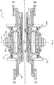
図4を参照して、減速ギア機構は、参照番号28で総称する貫通軸を有する構成である。この貫通軸は、別の構造に接続され、軸x−xの周りに支持体に相対的に適宜回転する。参照番号29で総称するサンギアが貫通軸に装着されている。参照番号30でそれぞれ示複数の遊星ギアが、サンギアに噛み合い、かつその周りに配置されている。これらの遊星ギアは、さらにリングギア25にも噛み合っている。ピニオン26もキー結合などによりリングギア25に移動可能に装着されている。好適実施例においては、ピニオン26の軸は、リングギア25の軸と同心である。
Referring to FIG. 4, the reduction gear mechanism is configured to have a through shaft generally designated by
図6を参照して、カップリングスリーブ31は、貫通軸28の左端にスプライン結合している。貫通軸は、参照番号32で総称する、左側に半径方向に拡大された部分と、リブすなわち支持体21の開口34を貫通する、右側に狭くなった部分33とを有している。貫通軸の左端部分は、ねじ付きであり、ワッシャ34およびナット35が設けられている。ワッシャ34の左面は、カップリングシール36に当接している。よって組立時、減速ギア機構は、二つのリブすなわち支持体の間に配置され、且つリングシャフトの小径部分33は、整合したリブの開口34,34に貫通している。この位置で。カップリングシール36は、貫通軸の右端部分上でスリップするようになり、ワッシャとナットは、組立状態を維持するべく設けられている。貫通軸33の侵入した縮小径部分が開口内でスリップすると、カップリングシャフトの歯のいくつかがサンギアの内側溝に係合し、相互にスプライン結合38が達成される。これにより、サンギア29は、貫通軸と共に回転することとなる。
Referring to FIG. 6, the
図5に明確に図示するように、各プラネットギアは、水平方向の細長管状部材となっており、右外向き歯21、中間外向き歯40ならびに左外向き歯42を有する。中間外向き歯40は、リングギア25の内向きギア歯40と噛み合う。前述のように、好適実施例では、ピニオンは、キイ結合(図示せず)などによりリングギアに脱着可能に装着され入る。よって外部ピニオンは、リングギアと共に回転する。
As clearly shown in FIG. 5, each planet gear is a horizontally elongated tubular member having right outward teeth 21, intermediate
図8に図示のように、支持構造44L,44Rは、左右のリブからそれぞれ互いの方向に延在している。これらの支持構造は、それらの内端ベアリング46L,46Rを支持する内方に延在する部分45L,45Rを有している。これらのベアリングは、サンギアおよび貫通軸組立体を支持体上に支承している。支持体44L,44Rは、それぞれピニオンの歯41,42と係合する内歯48L,48Rを有している。スペーサ49L,49Rは所望の間隔を保持するように機能すべくは位置されている。
As illustrated in FIG. 8, the
組立後の装置を図4に図示する。貫通軸28は、適切な角度方向に別の機構(図示せず)により適宜回転される。貫通軸が回転すると、サンギアが回転する。これにより遊星ギアが回転し、外部のリングギアとピニオンが回転する。よって、貫通軸が完全に一回転すると、リングギアおよびピニオンが一回転の何分の1かの回転をし、ラック23がトラック(図示せず)に沿って相当する移動を行い、回転の方向によりラックに取り付けられたフラップを適宜出し入れする。
The assembled device is illustrated in FIG. The through
前述したように、減速ギアユニットの一端に設けられた従来技術と異なり、本願発明の構成では、ピニオンの中心線は、減速ギアユニットの横断方向線(y−y)に一致している。これにより、ピニオンは、リングギア上に装着され、ピニオンの支承のための余分のベアリングを設ける必要がなくなる。むしろ、ピニオンは、減速ギアユニットのベアリングにより支持担持される。 As described above, unlike the prior art provided at one end of the reduction gear unit, in the configuration of the present invention, the center line of the pinion coincides with the transverse line (yy) of the reduction gear unit. As a result, the pinion is mounted on the ring gear, and there is no need to provide an extra bearing for supporting the pinion. Rather, the pinion is supported and supported by the bearing of the reduction gear unit.
さらなる新規な特徴は、改良コンパクトアクチュエータを支持構造に取り付ける方法にもある。図示のように、機構を物理的に二つの支持リブ21L,21Rの間に配置可能とし、かつ装着フランジ37(図1および図3)など適当な手段でピニオンに固定することが可能なように貫通軸が除去可能となっている。貫通軸の縮小径部分をサンギアおよび二つのリブの開口34,34に通すことができる。この後カップリングシールを縮小径部分33の右端部上をスリップさせ、部材33の右端部分に装着されたワッシャおよびナットで組立体を固定する。装置を除去するには、ナットおよびワッシャを除去し、貫通軸を引き抜くようにする。貫通軸を引き抜いてしまえば、二つのリブに間隔があるため減速ギア装置およびピニオンが物理的に除去できる。
A further novel feature lies in the way the improved compact actuator is attached to the support structure. As shown in the drawing, the mechanism can be physically disposed between the two
代替実施例として、改良機構は、リブの一つに簡単にボルト付けしても良い。この形式の機構の使用は、種々の部品およびコンポーネント構成に完全に依存するものである。 As an alternative embodiment, the improved mechanism may be simply bolted to one of the ribs. The use of this type of mechanism is entirely dependent on the various parts and component configurations.
以上をまとめると、本発明は、広義に支持体に対して被駆動体を適宜移動させるためのコンパクトアクチュエータを改良して提供するものである。改良アクチュエータは、広義に支持体に装着し、長手方向軸の周りに回転するリングギアを含む減速ギアユニットと、支承ベアリングの全てが減速ギアユニットに物理的に内蔵されるようにサンギアに装着されたピニオン26などの出力部材とを有し、出力部材が支持体に相対的に被駆動体を移動するべく動作するように結合されている。上述のように、出力部材は、ピニオンとすることができるが、別のギア列と噛み合う単なるギア、スプロケット、ドライブプーリその他の機構でも良い。
In summary, the present invention provides an improved compact actuator for appropriately moving a driven body relative to a support in a broad sense. The improved actuator is mounted on the support in a broad sense and mounted on the sun gear so that all of the reduction gear unit, including the ring gear that rotates around the longitudinal axis, and the bearings are physically built into the reduction gear unit. And an output member such as a
以上により、本発明の改良コンパクトアクチュエータを実施例の形式で図示説明したが、本願発明は、特許請求の範囲で定義される発明の概念の範囲で、様々に修正変更可能であるとは当業者に自明である。 Although the improved compact actuator of the present invention has been illustrated and described in the form of an embodiment, the present invention can be modified and changed in various ways within the scope of the concept of the invention defined in the claims. It is self-evident.
Claims (6)
前記リングギアに装着されたピニオン(26)と、
を有し、前記ピニオンは追加のベアリングを必要とせず、前記リングギア用のベアリングの全てが前記減速ギアユニット内に収められ、前記ピニオンは、その回転により翼面(27)を前記支持体に対して相対的に移動させるようにラックに動作結合されており、前記翼面(27)上に設けられたラック(23)を前記支持体に対して相対的に適宜移動させるコンパクトアクチュエータ(20)。A reduction gear mounted on a support (21) and having a ring gear (25) rotating around a longitudinal axis (xx ), a sun gear (29), and at least one planetary gear (30) meshing with the sun gear A unit (24) ;
A pinion (26) attached to the ring gear;
The pinion does not require an additional bearing, and all of the ring gear bearings are accommodated in the reduction gear unit, and the pinion rotates the blade surface (27) to the support body. is operatively coupled to the rack so as to relatively move against compact actuator relative to appropriately move the rack (23) provided on the blade surface (27) relative to the support (20 )
Applications Claiming Priority (3)
| Application Number | Priority Date | Filing Date | Title |
|---|---|---|---|
| US10/865,102 US7101297B2 (en) | 2004-06-10 | 2004-06-10 | Compact actuator |
| US10/865,102 | 2004-06-10 | ||
| PCT/US2005/020054 WO2005124192A2 (en) | 2004-06-10 | 2005-06-07 | Compact actuator |
Publications (2)
| Publication Number | Publication Date |
|---|---|
| JP2008502866A JP2008502866A (en) | 2008-01-31 |
| JP4820366B2 true JP4820366B2 (en) | 2011-11-24 |
Family
ID=35461233
Family Applications (1)
| Application Number | Title | Priority Date | Filing Date |
|---|---|---|---|
| JP2007527672A Active JP4820366B2 (en) | 2004-06-10 | 2005-06-07 | Compact actuator |
Country Status (7)
| Country | Link |
|---|---|
| US (1) | US7101297B2 (en) |
| EP (1) | EP1753979B1 (en) |
| JP (1) | JP4820366B2 (en) |
| CN (1) | CN100441920C (en) |
| DE (1) | DE602005015844D1 (en) |
| ES (1) | ES2329261T3 (en) |
| WO (1) | WO2005124192A2 (en) |
Families Citing this family (12)
| Publication number | Priority date | Publication date | Assignee | Title |
|---|---|---|---|---|
| KR100748656B1 (en) * | 2005-12-01 | 2007-08-10 | 현대자동차주식회사 | Power transmitting system for hybrid vehicle |
| FR2901591B1 (en) * | 2006-05-24 | 2009-01-16 | Valeo Embrayages | DEVICE FOR REDUCING THE IMBRITIC EPICYCLOIDAL TRAIN TYPE |
| US10400818B2 (en) | 2007-12-06 | 2019-09-03 | Roller Bearing Company Of America, Inc. | Track roller bearings with rolling elements or liners |
| GB0816022D0 (en) * | 2008-09-03 | 2008-10-08 | Airbus Uk Ltd | Slat support assembly |
| CN101988570B (en) * | 2009-07-31 | 2014-08-20 | 中国商用飞机有限责任公司 | Design method of gears and racks for airplane slat actuators |
| FR2952348B1 (en) * | 2009-11-10 | 2012-03-09 | Airbus Operations Sas | CROCODILE AERODYNAMIC GOVERNMENT FOR AIRCRAFT |
| KR101009742B1 (en) | 2010-10-29 | 2011-01-19 | 주식회사 세진아이지비 | A transmission device for converting a torque |
| GB201111922D0 (en) | 2011-07-12 | 2011-08-24 | Airbus Operations Ltd | Leading edge rib assembly |
| DE102014007266A1 (en) * | 2014-05-16 | 2015-11-19 | Liebherr-Aerospace Lindenberg Gmbh | High-load gearbox for a high-lift carrier, high-lift carrier, as well as flap unit and method for mounting flaps |
| FR3028836B1 (en) * | 2014-11-20 | 2016-12-16 | Sagem Defense Securite | ACTUATOR FLIGHT CONTROL ACTUATOR OF AN AIRCRAFT |
| US9249861B2 (en) | 2015-05-06 | 2016-02-02 | Diakont Advanced Technologies, Inc. | Transmission gear, roller reducer comprising the transmission gear, and method of assembly thereof |
| CN112109878B (en) * | 2020-08-23 | 2023-01-10 | 北京航空航天大学 | Folding mechanism suitable for folding morphing wing |
Citations (2)
| Publication number | Priority date | Publication date | Assignee | Title |
|---|---|---|---|---|
| US4838503A (en) * | 1987-05-13 | 1989-06-13 | British Aerospace Plc | Mechanism for supporting and extending a high lift device for aircraft wings |
| JP2004108582A (en) * | 2002-09-13 | 2004-04-08 | Moog Inc | Combination type differential planetary gear assembly |
Family Cites Families (18)
| Publication number | Priority date | Publication date | Assignee | Title |
|---|---|---|---|---|
| US1586944A (en) * | 1922-05-23 | 1926-06-01 | Ruckstell Sales & Mfg Company | Planetary-gear mechanism |
| US1917428A (en) | 1927-12-17 | 1933-07-11 | Uppercu Burnelli Corp | Aircraft |
| GB718645A (en) * | 1951-05-16 | 1954-11-17 | Ciotat La | Improvements in or relating to transmission devices |
| US2959070A (en) * | 1959-01-09 | 1960-11-08 | Borg Warner | Accessory drive |
| US4043216A (en) * | 1974-10-11 | 1977-08-23 | Lucas Industries Limited | Compound pinions for use in epicyclic gear boxes |
| DE2847513A1 (en) * | 1978-11-02 | 1980-05-14 | Curtiss Wright Corp | Free-floating planetary transmission - has ring gear coaxial with transmission surrounding planetary elements with spindles having axially spaced gears |
| US4305488A (en) * | 1979-11-13 | 1981-12-15 | Borg-Warner Corporation | Accessory drive system |
| US4471928A (en) | 1980-08-13 | 1984-09-18 | The Boeing Company | Extendible airfoil track assembly |
| US4691584A (en) * | 1985-02-20 | 1987-09-08 | Ohi Seisakusho Co., Ltd. | Actuator for remote devices or the like |
| US4753402A (en) * | 1985-12-30 | 1988-06-28 | The Boeing Company | Biased leading edge slat apparatus |
| US4995575A (en) | 1988-09-26 | 1991-02-26 | The Boeing Company | Wing trailing edge flap mechanism |
| DE4030489A1 (en) * | 1990-09-26 | 1992-04-02 | Man Ghh Logistics | PLANETARY GEARBOX |
| US5544847A (en) | 1993-11-10 | 1996-08-13 | The Boeing Company | Leading edge slat/wing combination |
| GB2304656B (en) | 1995-08-26 | 1999-10-13 | British Aerospace | Deployment mechanisms for aircraft auxiliary aerofoils |
| JPH11303977A (en) * | 1998-04-22 | 1999-11-02 | Matex Kk | Casing fitting structure of planetary gear device |
| JP3888834B2 (en) * | 2000-04-25 | 2007-03-07 | ダイハツ工業株式会社 | Automatic transmission for vehicles |
| JP2003166557A (en) * | 2001-11-30 | 2003-06-13 | Exedy Corp | Actuator of clutch |
| ITPD20020223A1 (en) * | 2002-09-03 | 2004-03-04 | Carraro Spa | EMBRICATE TYPE EPICLOIDAL REDUCER. |
-
2004
- 2004-06-10 US US10/865,102 patent/US7101297B2/en active Active
-
2005
- 2005-06-07 EP EP05757487A patent/EP1753979B1/en not_active Expired - Fee Related
- 2005-06-07 CN CNB2005800188556A patent/CN100441920C/en not_active Expired - Fee Related
- 2005-06-07 DE DE602005015844T patent/DE602005015844D1/en active Active
- 2005-06-07 JP JP2007527672A patent/JP4820366B2/en active Active
- 2005-06-07 WO PCT/US2005/020054 patent/WO2005124192A2/en not_active Application Discontinuation
- 2005-06-07 ES ES05757487T patent/ES2329261T3/en active Active
Patent Citations (2)
| Publication number | Priority date | Publication date | Assignee | Title |
|---|---|---|---|---|
| US4838503A (en) * | 1987-05-13 | 1989-06-13 | British Aerospace Plc | Mechanism for supporting and extending a high lift device for aircraft wings |
| JP2004108582A (en) * | 2002-09-13 | 2004-04-08 | Moog Inc | Combination type differential planetary gear assembly |
Also Published As
| Publication number | Publication date |
|---|---|
| WO2005124192A3 (en) | 2006-06-01 |
| CN100441920C (en) | 2008-12-10 |
| US20050277513A1 (en) | 2005-12-15 |
| EP1753979A4 (en) | 2007-12-26 |
| EP1753979B1 (en) | 2009-08-05 |
| WO2005124192A2 (en) | 2005-12-29 |
| US7101297B2 (en) | 2006-09-05 |
| DE602005015844D1 (en) | 2009-09-17 |
| EP1753979A2 (en) | 2007-02-21 |
| CN1965182A (en) | 2007-05-16 |
| WO2005124192B1 (en) | 2006-08-17 |
| ES2329261T3 (en) | 2009-11-24 |
| JP2008502866A (en) | 2008-01-31 |
Similar Documents
| Publication | Publication Date | Title |
|---|---|---|
| JP4820366B2 (en) | Compact actuator | |
| JP6298817B2 (en) | Landing gear drive system | |
| JP6450382B2 (en) | Small structure for aircraft turbine engine accessory gearbox | |
| JP2019135156A (en) | Landing device drive system | |
| US7784731B2 (en) | Transmission device for a twin-rotor helicopter | |
| JP5069892B2 (en) | Differential oscillating speed reducer | |
| JP2008208867A (en) | Strain wave reduction gear, and variable transmission ratio steering system | |
| CN102472076A (en) | Drive device of a vehicle component, particularly a body hatch | |
| CN206432837U (en) | A kind of automobile power back door reducing motor | |
| CN106787426A (en) | A kind of automobile power back door reducing motor | |
| WO2009133750A1 (en) | Solar power generating device | |
| CA2954108C (en) | Planetary gear assembly | |
| CN219712353U (en) | Double-flange pneumatic butterfly valve | |
| US2368133A (en) | Motor-vehicle top construction | |
| JP2012112455A (en) | Orthogonal shaft geared motor | |
| CN107542860B (en) | Turnover driving device of vehicle-mounted flat panel display | |
| CN110886815B (en) | Gear transmission steering device of aircraft landing gear | |
| CN102126192A (en) | Turning hollow automatic spanner | |
| CN110626232A (en) | Drive for adjusting the lifting of a vehicle seat and vehicle seat with such a drive | |
| CN110614955B (en) | Electric pedal of vehicle door and vehicle | |
| CN209853080U (en) | Shifting fork mechanism and shuttle | |
| CN218668979U (en) | Control type gear driving device | |
| JP2023183482A (en) | actuator | |
| CN213039926U (en) | Multi-rotation gear reduction box for valve | |
| CN212986205U (en) | Double-drive speed reducer |
Legal Events
| Date | Code | Title | Description |
|---|---|---|---|
| A977 | Report on retrieval |
Free format text: JAPANESE INTERMEDIATE CODE: A971007 Effective date: 20100625 |
|
| A131 | Notification of reasons for refusal |
Free format text: JAPANESE INTERMEDIATE CODE: A131 Effective date: 20100629 |
|
| A521 | Request for written amendment filed |
Free format text: JAPANESE INTERMEDIATE CODE: A523 Effective date: 20100929 |
|
| A131 | Notification of reasons for refusal |
Free format text: JAPANESE INTERMEDIATE CODE: A131 Effective date: 20101119 |
|
| A131 | Notification of reasons for refusal |
Free format text: JAPANESE INTERMEDIATE CODE: A131 Effective date: 20110415 |
|
| TRDD | Decision of grant or rejection written | ||
| A01 | Written decision to grant a patent or to grant a registration (utility model) |
Free format text: JAPANESE INTERMEDIATE CODE: A01 Effective date: 20110819 |
|
| A01 | Written decision to grant a patent or to grant a registration (utility model) |
Free format text: JAPANESE INTERMEDIATE CODE: A01 |
|
| A61 | First payment of annual fees (during grant procedure) |
Free format text: JAPANESE INTERMEDIATE CODE: A61 Effective date: 20110902 |
|
| FPAY | Renewal fee payment (event date is renewal date of database) |
Free format text: PAYMENT UNTIL: 20140909 Year of fee payment: 3 |
|
| R150 | Certificate of patent or registration of utility model |
Ref document number: 4820366 Country of ref document: JP Free format text: JAPANESE INTERMEDIATE CODE: R150 Free format text: JAPANESE INTERMEDIATE CODE: R150 |
|
| R250 | Receipt of annual fees |
Free format text: JAPANESE INTERMEDIATE CODE: R250 |
|
| R250 | Receipt of annual fees |
Free format text: JAPANESE INTERMEDIATE CODE: R250 |
|
| R250 | Receipt of annual fees |
Free format text: JAPANESE INTERMEDIATE CODE: R250 |
|
| R250 | Receipt of annual fees |
Free format text: JAPANESE INTERMEDIATE CODE: R250 |
|
| R250 | Receipt of annual fees |
Free format text: JAPANESE INTERMEDIATE CODE: R250 |
|
| R250 | Receipt of annual fees |
Free format text: JAPANESE INTERMEDIATE CODE: R250 |
|
| R250 | Receipt of annual fees |
Free format text: JAPANESE INTERMEDIATE CODE: R250 |
|
| R250 | Receipt of annual fees |
Free format text: JAPANESE INTERMEDIATE CODE: R250 |
|
| R250 | Receipt of annual fees |
Free format text: JAPANESE INTERMEDIATE CODE: R250 |