JP6450382B2 - Small structure for aircraft turbine engine accessory gearbox - Google Patents
Small structure for aircraft turbine engine accessory gearbox Download PDFInfo
- Publication number
- JP6450382B2 JP6450382B2 JP2016524873A JP2016524873A JP6450382B2 JP 6450382 B2 JP6450382 B2 JP 6450382B2 JP 2016524873 A JP2016524873 A JP 2016524873A JP 2016524873 A JP2016524873 A JP 2016524873A JP 6450382 B2 JP6450382 B2 JP 6450382B2
- Authority
- JP
- Japan
- Prior art keywords
- gear
- drive chain
- drive
- chain according
- forming
- Prior art date
- Legal status (The legal status is an assumption and is not a legal conclusion. Google has not performed a legal analysis and makes no representation as to the accuracy of the status listed.)
- Expired - Fee Related
Links
Images


Classifications
-
- B—PERFORMING OPERATIONS; TRANSPORTING
- B64—AIRCRAFT; AVIATION; COSMONAUTICS
- B64C—AEROPLANES; HELICOPTERS
- B64C27/00—Rotorcraft; Rotors peculiar thereto
- B64C27/04—Helicopters
- B64C27/12—Rotor drives
-
- F—MECHANICAL ENGINEERING; LIGHTING; HEATING; WEAPONS; BLASTING
- F02—COMBUSTION ENGINES; HOT-GAS OR COMBUSTION-PRODUCT ENGINE PLANTS
- F02C—GAS-TURBINE PLANTS; AIR INTAKES FOR JET-PROPULSION PLANTS; CONTROLLING FUEL SUPPLY IN AIR-BREATHING JET-PROPULSION PLANTS
- F02C7/00—Features, components parts, details or accessories, not provided for in, or of interest apart form groups F02C1/00 - F02C6/00; Air intakes for jet-propulsion plants
- F02C7/32—Arrangement, mounting, or driving, of auxiliaries
-
- F—MECHANICAL ENGINEERING; LIGHTING; HEATING; WEAPONS; BLASTING
- F16—ENGINEERING ELEMENTS AND UNITS; GENERAL MEASURES FOR PRODUCING AND MAINTAINING EFFECTIVE FUNCTIONING OF MACHINES OR INSTALLATIONS; THERMAL INSULATION IN GENERAL
- F16H—GEARING
- F16H1/00—Toothed gearings for conveying rotary motion
- F16H1/28—Toothed gearings for conveying rotary motion with gears having orbital motion
-
- F—MECHANICAL ENGINEERING; LIGHTING; HEATING; WEAPONS; BLASTING
- F05—INDEXING SCHEMES RELATING TO ENGINES OR PUMPS IN VARIOUS SUBCLASSES OF CLASSES F01-F04
- F05D—INDEXING SCHEME FOR ASPECTS RELATING TO NON-POSITIVE-DISPLACEMENT MACHINES OR ENGINES, GAS-TURBINES OR JET-PROPULSION PLANTS
- F05D2260/00—Function
- F05D2260/40—Transmission of power
- F05D2260/403—Transmission of power through the shape of the drive components
- F05D2260/4031—Transmission of power through the shape of the drive components as in toothed gearing
- F05D2260/40311—Transmission of power through the shape of the drive components as in toothed gearing of the epicyclical, planetary or differential type
-
- F—MECHANICAL ENGINEERING; LIGHTING; HEATING; WEAPONS; BLASTING
- F16—ENGINEERING ELEMENTS AND UNITS; GENERAL MEASURES FOR PRODUCING AND MAINTAINING EFFECTIVE FUNCTIONING OF MACHINES OR INSTALLATIONS; THERMAL INSULATION IN GENERAL
- F16C—SHAFTS; FLEXIBLE SHAFTS; ELEMENTS OR CRANKSHAFT MECHANISMS; ROTARY BODIES OTHER THAN GEARING ELEMENTS; BEARINGS
- F16C19/00—Bearings with rolling contact, for exclusively rotary movement
- F16C19/54—Systems consisting of a plurality of bearings with rolling friction
-
- F—MECHANICAL ENGINEERING; LIGHTING; HEATING; WEAPONS; BLASTING
- F16—ENGINEERING ELEMENTS AND UNITS; GENERAL MEASURES FOR PRODUCING AND MAINTAINING EFFECTIVE FUNCTIONING OF MACHINES OR INSTALLATIONS; THERMAL INSULATION IN GENERAL
- F16H—GEARING
- F16H1/00—Toothed gearings for conveying rotary motion
- F16H1/28—Toothed gearings for conveying rotary motion with gears having orbital motion
- F16H2001/2881—Toothed gearings for conveying rotary motion with gears having orbital motion comprising two axially spaced central gears, i.e. ring or sun gear, engaged by at least one common orbital gear wherein one of the central gears is forming the output
-
- Y—GENERAL TAGGING OF NEW TECHNOLOGICAL DEVELOPMENTS; GENERAL TAGGING OF CROSS-SECTIONAL TECHNOLOGIES SPANNING OVER SEVERAL SECTIONS OF THE IPC; TECHNICAL SUBJECTS COVERED BY FORMER USPC CROSS-REFERENCE ART COLLECTIONS [XRACs] AND DIGESTS
- Y02—TECHNOLOGIES OR APPLICATIONS FOR MITIGATION OR ADAPTATION AGAINST CLIMATE CHANGE
- Y02T—CLIMATE CHANGE MITIGATION TECHNOLOGIES RELATED TO TRANSPORTATION
- Y02T50/00—Aeronautics or air transport
- Y02T50/60—Efficient propulsion technologies, e.g. for aircraft
Description
本発明は、航空機内に存在するギアチェーン(または駆動チェーン)に関する。 The present invention relates to a gear chain (or drive chain) present in an aircraft.
これらのギアチェーンは、始動機によって駆動されるとき、その始動段階において、たとえばタービンエンジンの始動機または圧縮機などの駆動部材と、たとえば発電機または油圧ポンプのような補機などの従動部材との間で、機械動力を伝達するために使用される。補機ギアボックスすなわちAGBは、補機を駆動するためのギアチェーンの一具体例である。このタイプの補機ギアボックス構造は、米国特許出願公開第2012/0006137号明細書に記載されている。 When these gear chains are driven by a starter, in their starting phase, they are driven members such as starters or compressors of turbine engines and driven members such as accessories such as generators or hydraulic pumps. Used to transfer mechanical power between. An accessory gearbox or AGB is a specific example of a gear chain for driving an accessory. This type of accessory gearbox structure is described in US 2012/0006137.
増速機または減速機機能は通常、入力運動の回転速度を各駆動部材または従動部材の特定パラメータに適合させるために使用される。 The speed increaser or speed reducer function is typically used to adapt the rotational speed of the input motion to specific parameters of each drive member or follower member.
たとえば、始動機は2つの部分を備える:羽根車と称される可動部材と、減速機である。 For example, a starter comprises two parts: a movable member called an impeller and a speed reducer.
しかしながら、いくつかの具体的事例において、駆動部材および従動部材は分離していなければならない。たとえば、始動機の機能自体は、タービンエンジンの始動を支援するものである。タービンエンジンが所望の回転速度に到達すると、始動機は切断されなければならない。 However, in some specific cases, the drive member and follower member must be separated. For example, the starter function itself assists in starting the turbine engine. When the turbine engine reaches the desired rotational speed, the starter must be disconnected.
本発明は、増速機または減速機機能を統合し、駆動チェーンおよび/または補機の寸法を縮小するために接続を断つことが可能な、小型構造を提案することを目指す。 The present invention seeks to propose a compact structure that integrates speed increaser or speed reducer functions and can be disconnected to reduce drive chain and / or accessory dimensions.
したがって本発明は、互いに噛合する複数のメインギアを含む、たとえばタービンエンジンの補機駆動チェーンなどの航空機駆動チェーンに関し、第一メインギアは内部空間を画定する壁を備え、外部セットのギア歯は壁の外表面上に配置され、外部セットのギア歯は少なくとも1つの第二メインギアと噛合し、複数のメインギアとは別のギアシステムが内部空間に組み込まれ、第一メインギアおよびギアシステムは、増速機または減速機を形成して駆動部材と従動部材との間の機械動力伝達を確保するように連帯して構成され、前記ギアシステムはデカップリング部材によって壁に実装されている。 The present invention thus relates to an aircraft drive chain, such as a turbine engine accessory drive chain, including a plurality of meshing main gears, wherein the first main gear comprises a wall defining an interior space, and the external set of gear teeth An outer set of gear teeth is disposed on the outer surface of the wall and meshes with at least one second main gear, and a gear system separate from the plurality of main gears is incorporated in the interior space, the first main gear and the gear system Are configured to be joined together so as to form a speed increaser or a speed reducer to ensure mechanical power transmission between the driving member and the driven member, and the gear system is mounted on the wall by a decoupling member.
本発明はさらに、たとえばタービンエンジンの補機駆動チェーンなどの航空機駆動チェーンに関し、駆動チェーンは互いに噛合する複数のギアを含み、駆動チェーンは、デカップリング部材のみならず、ギアシステムを形成する第二の複数のギアをさらに含み、第一の複数のギアおよび第二の複数のギアはデカップリング部材によって接続され、第一の複数のギアの第一ギアは内部空間を画定する壁を備え、外部セットのギア歯は壁の外表面上に配置され、外部セットのギア歯は第一の複数のギアの少なくとも1つの第二ギアと噛合し、ギアシステムは内部空間に組み込まれ、第一ギアおよびギアシステムは、増速機または減速機を形成して駆動部材と従動部材との間の機械動力を確保するように連帯して構成され、前記ギアシステムはデカップリング部材によって壁に実装されている。 The invention further relates to an aircraft drive chain, such as a turbine engine accessory drive chain, the drive chain including a plurality of gears that mesh with each other, the drive chain forming a gear system as well as a decoupling member. A plurality of gears, wherein the first plurality of gears and the second plurality of gears are connected by a decoupling member, the first gears of the first plurality of gears having a wall defining an interior space, The set gear teeth are disposed on the outer surface of the wall, the outer set gear teeth mesh with at least one second gear of the first plurality of gears, the gear system is incorporated into the interior space, the first gear and The gear system is configured so as to form a speed increaser or a speed reducer so as to secure mechanical power between the driving member and the driven member, and the gear system is a deca It is mounted on the wall by pulling member.
本発明はこのように、駆動部材または従動部材自体の内部空間ではなく、航空機ギアチェーンのギアの内部空間において、航空機の増速機(および/または減速機)構造と駆動部材または従動部材のためのデカップリング部材との統合および関連付けを、可能にする。これにより、この補機によって占有される体積、ならびにカンチレバー位置にある重量を、減少させる。これは有利なことに、一方ではこの部材を支持する継手にかかる応力を低下させ、他方ではギアチェーンがその中に組み立てられるモジュールの内部体積を最適化する結果となる。さらに、この統合は、駆動チェーンの体積を増加させることなく、ギアによって画定された空間内で行われる。 The present invention thus provides for the gearbox (and / or speed reducer) structure and drive or driven member of an aircraft in the internal space of the gear of the aircraft gear chain rather than the internal space of the drive or driven member itself. Enables integration and association with a decoupling member. This reduces the volume occupied by this accessory as well as the weight at the cantilever position. This advantageously results on the one hand in reducing the stress on the joint supporting this member and on the other hand optimizing the internal volume of the module in which the gear chain is assembled. Furthermore, this integration takes place in the space defined by the gear without increasing the volume of the drive chain.
AGBの具体的事例において、補機体積の減少は、タービンエンジン内のその統合を容易にする。 In the specific case of AGB, the reduction in accessory volume facilitates its integration within the turbine engine.
また、デカップリング部材は、運動入力および運動出力における特定の回転条件の下でのみ、駆動部材または従動部材が動作できるようにする。たとえば、先に説明されたようにその増速機がギアに統合されている航空機タービンエンジンの始動機は、タービンエンジン始動においてのみ有利に動作することができる。 The decoupling member also allows the drive member or follower member to operate only under specific rotational conditions at the motion input and motion output. For example, an aircraft turbine engine starter whose gearbox is integrated into a gear as described above can operate advantageously only at the turbine engine start.
1つの有利な特徴によれば、前記ギアシステムは、クラウンを形成する部材、少なくとも2つの遊星歯車、遊星キャリアを形成する部材、および太陽歯車歯セットを備え、太陽歯車歯セットは駆動部材または従動部材に接続された第一シャフト上に配置され、内部セットのギア歯はクラウンを形成する部材の内表面に配置され、遊星歯車は内部セットのギア歯および太陽歯車歯セットと噛合する。 According to one advantageous feature, the gear system comprises a member forming a crown, at least two planet gears, a member forming a planet carrier, and a sun gear tooth set, the sun gear tooth set being a drive member or a driven member. Located on the first shaft connected to the member, the inner set of gear teeth is located on the inner surface of the member forming the crown, and the planetary gear meshes with the inner set of gear teeth and the sun gear tooth set.
有利なことに、クラウンを形成する部材は、デカップリング部材の内側軌道がその上に作られるリムを備え、遊星キャリアを形成する部材は航空機フレームに対して固定されている。 Advantageously, the member forming the crown comprises a rim on which the inner track of the decoupling member is made, and the member forming the planet carrier is fixed relative to the aircraft frame.
あるいは、クラウンを形成する部材は、航空機フレームに対して固定されているリング状の壁を備え、遊星キャリアを形成する部材は、デカップリング部材の内側軌道がその上に作られるリムを備える。 Alternatively, the member forming the crown comprises a ring-like wall that is fixed relative to the aircraft frame, and the member forming the planet carrier comprises a rim on which the inner track of the decoupling member is made.
1つの有利な特徴によれば、第一メインギアに向かう運動は、外部セットのギア歯によって開始される。 According to one advantageous feature, the movement towards the first main gear is initiated by an external set of gear teeth.
あるいは、第一メインギアに向かう運動は、第一シャフトによって開始される。 Alternatively, movement toward the first main gear is initiated by the first shaft.
1つの有利な特徴によれば、デカップリング部材は、第一メインギアの回転速度がクラウンを形成する部材の回転速度よりも速いとき、またはギアの回転速度が設定値に到達したときに遠心力によって生じる離脱によって、ギアシステムおよび第一メインギアの回転分離を許容するように構成されている。 According to one advantageous feature, the decoupling member has a centrifugal force when the rotational speed of the first main gear is faster than the rotational speed of the member forming the crown, or when the rotational speed of the gear reaches a set value. Is configured to allow rotational separation of the gear system and the first main gear.
特定の一実施形態によれば、デカップリング部材は、オーバーランニングクラッチ装置を備える。 According to one particular embodiment, the decoupling member comprises an overrunning clutch device.
特定の一実施形態によれば、ギアシステムの遊星歯車は各々、直径の異なるギア歯の第一および第二セットを有する。 According to one particular embodiment, the planetary gears of the gear system each have first and second sets of gear teeth of different diameters.
このようなギア歯の二重セットは有利なことに、最小限の空間内の高変速範囲を提供する。 Such a double set of gear teeth advantageously provides a high speed range within a minimum space.
特定の一実施形態において、前記第一メインギアは、第一シャフトと同軸の第二シャフトを備える。 In one particular embodiment, the first main gear comprises a second shaft that is coaxial with the first shaft.
したがって本発明は有利なことに、2つの補機が互いに反対側に位置して、一方ではギアの寸法に応じて、他方ではギアボックスに応じて、非常に異なる速度で回転できるようにする。 The present invention thus advantageously allows two auxiliaries to be located opposite one another and to rotate at very different speeds, depending on the size of the gear on the one hand and on the other hand on the gearbox.
1つの具体的構成において、第一メインギアは、リングおよびピニオンの一部を形成する。 In one specific configuration, the first main gear forms part of the ring and pinion.
たとえば、AGBの第一メインギアは圧縮機シャフトに最も近いギアであることが、可能である。 For example, the first main gear of the AGB can be the gear closest to the compressor shaft.
先に説明された駆動チェーンはたとえば、AGB、PGB(発電ギアボックス:Power GearBox)、RGB(減速ギアボックス:Reduction GearBox)、RAT(ラムエアタービン:Ram Air Turbine)、またはAPU(補助動力装置:Auxiliary Power Unit)駆動装置を対象とする。 The drive chains described above are, for example, AGB, PGB (Power Gear Box), RGB (Reduction Gear Box), RAT (Ram Air Turbine), or APU (Auxiliary Power Unit: Auxiliary). Power Unit) drive device.
本発明はまた、先に説明されたような駆動チェーンを備える補機ギアボックスにも関する。 The invention also relates to an accessory gearbox comprising a drive chain as previously described.
本発明はさらに、先に説明されたような駆動チェーンを備えるプロペラ用ギアボックスにも関する。 The invention further relates to a propeller gearbox comprising a drive chain as described above.
以下、本文献は、非限定例により、下記の添付図面を参照して本発明の実施形態を説明する。 Hereinafter, this document will describe embodiments of the present invention by way of non-limiting examples with reference to the accompanying drawings.
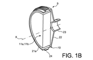
図1Aは、縦方向Xに配向された、全体的にじょうご型の形状を有するギア10を示す。
FIG. 1A shows a
ギア10は、リング状のリム21a、ホイールディスク22、支柱23、および外部セットのギア歯24を備える。
The
リム21aおよび支柱23は円筒形で同軸であり、円形断面を有しており、支柱23の直径はリム21aの直径よりも小さい。支柱23はこの例において中空シャフトである。あるいは、支柱23は中実シャフトである。
The
この例のホイールディスク22は、円錐台形状を有する。ホイールディスク22は、第一円形縁22aによってリム21aの端縁に、そして第一縁22aよりも小さい直径を有する第二円形縁22bによって支柱23の端片に、接続されている。あるいは、図示されないが、ホイールディスク22は平坦である。ホイールディスク22はまた、その表面の一部に開口部を備えることもできる。
The
リム21aおよびホイールディスク22は、連帯して内部筐体12を画定する。
The
支柱23は、内部筐体12の反対側にホイールディスク22から延在する。
The
外部セットのギア歯24は、リム21aから径方向外向きに延在する。この例におけるギア歯のセット24は、直歯を備える。あるいは、図示されないが、このギア歯のセットは、螺旋状またはその他のタイプのギア歯である。
The external set of
図1Bは、増速機11aおよびデカップリング部材11bが先に説明されたギア10の内部筐体12の中に実装されている、機械装置9を示す。図1Bにおいて、増速機11aおよびデカップリング部材11bは、シリンダを半分にして簡素化された形で示されている。
FIG. 1B shows a
図3および図4に示される装置9において、増速機11aは、クラウン30、遊星歯車40(または遊星)、遊星キャリア41、およびシャフト42を備える。
In the
クラウン30は、リング状のリム21bおよび内部セットのギア歯25を備える。リム21bは円形断面を有する。ギア歯のセット25は、リム21bの内表面上を径方向に延在する。この例のギア歯のセット25は直歯を備える。あるいは、図示されないが、このギア歯のセットは螺旋状またはその他のタイプのギア歯である。
The
遊星40はこの例において、2セットの直歯49aおよび49bを有するギアである。より正確には、遊星40は2つの異なる外部セットのギア歯を備える、一方のセット49aはこの例において他方のセット49bよりも大きい直径を有する。この例には、4つの遊星40がある。あるいは、図示されないが、ギア歯のセット49aおよび49bは螺旋状またはその他のタイプのギア歯であり、および/または遊星歯車40の数はたとえば4まで様々であり、たとえば2または3である。
In this example, the
この例において、ギア歯のセット49bは、クラウン30のギア歯のセット25と噛合する。
In this example, the gear tooth set 49 b meshes with the gear tooth set 25 of the
図示される実施形態において、遊星キャリア41は、2つのシェル41aおよび41bならびに4つのシャフト44を備える。
In the illustrated embodiment, the
ホイールディスク22から最も遠くに位置する第一シェル41aは、壁43a、円筒形部分45a、および継手48を備える。壁43は平坦フランジである。円筒形部分45aは、支柱23の反対側で、壁43aから縦に延在する。円錐台形部分47は、円筒形部分45aの突起の中に向かって収縮することによって延在する。最後に、遊星キャリア41の支柱48は、縦配向Xに対して直角に、円錐台形部分47の遠位末端に位置決めされる。継手48は、たとえばギアボックス4aまたは4bのうちの1つなど、固定フレームに関連して所定位置に遊星キャリア41を保持する。
The
ホイールディスク22に最も近い位置にある第二シェル41bは、壁43bおよび円筒形部分45bを備える。壁43bは平坦フランジである。あるいは、壁43aおよび/または43bは、図示されるものとは異なる形状を有する。たとえば、これらの壁のいずれかは、開口部を含むことができ、または平坦要素とは異なってもよい。円筒形部分45bは、支柱23に向かって壁43bから縦に延在する。
The
2つの軸受46b、この例ではころ軸受は、クラウン30のリム21bと円筒形部分45aおよび45bとの間に機械的な回転連結を提供する。
Two
壁43aおよび43bは、互いに平行である。これらの壁43aおよび43bは、その上に遊星歯車40が実装されて回転運動することができるシャフト44を、連帯して支持する。
The
シャフト42は、遊星キャリア41内に収容された末端の中に、直線的なギア歯のセット50を有する。図示されないバージョンでは、このギア歯のセットは螺旋状またはその他のタイプのギア歯である。このギア歯のセット50は、4つの遊星40の各々のギア歯のセット49aと噛合する。この例のシャフト42は、支柱23およびリム21aと同軸である。
The
この例のデカップリング部材11bは、オーバーランニングクラッチ装置51および2つの軸受46a、この例では玉軸受を、備える。
The
オーバーランニングクラッチ装置51および2つの軸受46aはギア10のリム21aとクラウン30のリム21bとの間に挿入され、オーバーランニングクラッチ装置51は2つの軸受46aの間に位置決めされる。
The overrunning
オーバーランニングクラッチ装置51は、1つのリング状ユニットによって簡素化された形で図3および図4に示される。一般的なやり方では、オーバーランニングクラッチ装置51は2つのリング状の軌道を備える。外側軌道は、リム21a内に、またはリム21a内に実装された別のリング内に、形成される。内側軌道は、リム21b内に、またはリム21bの周りに実装された別のリング内に、形成される。
The overrunning
航空機タービンエンジン始動機の具体的な非限定例において、航空機の始動時に、動力はまず、始動機のタービンからAGBを介して航空機のモータまで伝達される。オーバーランニングクラッチ装置51は、トルクがクラウン30からメインギア10まで伝達される際に噛合する。一旦モータが始動すると、
トルクが航空機のモータから始動機まで伝達されるまでトルク伝達方向が逆転されるとき、または
ギア10の回転速度が設定値に到達したときに遠心力によって生じる離脱によって、
オーバーランニングクラッチ装置51はクラウン30およびギア10を回転中に分離させることができる。
In a specific non-limiting example of an aircraft turbine engine starter, when the aircraft is started, power is first transferred from the starter turbine to the aircraft motor via the AGB. The overrunning
When the torque transmission direction is reversed until torque is transmitted from the aircraft motor to the starter, or when the rotational speed of the
The overrunning
図2Aおよび図2Bに見られるように、ギア10は、ギアチェーン(または運動リンケージ)内に異なるやり方で統合されることが可能である。
As seen in FIGS. 2A and 2B, the
図2Aにおいて、ギア10はギアボックス4aの第一運動リンケージ5内に実装される。より正確には、ギア10は、24a内の上流でははめば歯車13と、および下流24bでははめば歯車14と、噛合する。用語「上流」は、はめば歯車13が、運動リンケージ5の中で、そこから機械的運動が生じる圧縮機シャフトに最も近いことを意味するものとして、理解される。こうしてはめば歯車13の回転は、ギア10および下流に実装されたはめば歯車14を駆動する。
In FIG. 2A, the
図2Bにおいて、ギア10は、ギアボックス4bの第二運動リンケージ6内に実装される。この例において、ギア10は24c内ではめば歯車15と噛合し、運動リンケージ6の末端に実装されている。
In FIG. 2B, the
あるいは、圧縮機シャフトからのギアボックス4a内の運動はギア10によって開始され、すなわちギア10は、それぞれギア13および14(図2A)または15(図2B)を備える、ギアチェーン5または6に動力を供給する。
Alternatively, movement in the
図2Aおよび図2Bの例は限定的ではなく、ギア10は、図2Aおよび図2Bに示されるものとの運動リンケージ内の、または図とは異なる運動リンケージ内の様々な場所に、実装されることが可能である。
The example of FIGS. 2A and 2B is not limiting, and the
あるいは、図示されないが、ギアはリングおよびピニオンの一部であり、外部セットのギア歯はたとえば円錐形または円錐台形のリム上に形成される。 Alternatively, although not shown, the gear is part of the ring and pinion, and the outer set of gear teeth is formed on a rim, for example of a conical or frustoconical shape.
ギア10は、たとえばころ軸受または滑り軸受などの軸受を介して支柱23に実装された継手によって、航空機の固定フレームに対して所定位置に保持される(固定フレーム、継手、および軸受は、ここでは図示されない)。
The
図3および図4に示される装置9は、駆動システムの上流部が支柱23、ギア歯のセット24、またはシャフト42に最も近い側に位置しているか否かに応じて、ギアボックスとして、または減速機として、使用されることが可能である。
The
増速機11aは複合遊星歯車システム(すなわち、2セットのギア歯49aおよび49bを有する遊星40を備える)の形態で本例に存在し、ここでクラウン30は内部セットのギア歯25を介した外側遊星歯車であり、シャフト42上に位置決めされたギア歯のセット50は内側可動遊星歯車(または太陽歯車)の役割を果たし、遊星キャリア41は固定フレームに固定されている。2セットのギア歯を有する遊星の使用は、単一ギアよりも大きい変速範囲を生じる。それでもなお、本発明はまた、単一ギアの形態の、すなわちクラウンおよびシャフト42のギア歯のセット50の両方と噛合した同じギア歯のセットを有する、遊星歯車の実現にも及ぶ。
The step-up
有利なことに、本発明はさらに、2つの部材が互いに反対側に位置決めされて異なる速度で回転し、1つはシャフト42に回転可能に接続され、他方は支柱23または支柱23に接続されたシャフトに接続されることを、可能にする。
Advantageously, the present invention further provides that the two members are positioned opposite to each other and rotate at different speeds, one rotatably connected to the
図5に示される装置209は、図3および図4を参照して記載された装置9の代替例である。装置9および209に共通の部品は、同じ参照番号を付されており、再度記載されることはない。
The
装置209は、ギア210、クラウン241、および壁243を備える。
壁243は、シャフト44およびひいては遊星歯車40が実装される遊星キャリアを形成する。壁243は、オーバーランニングクラッチ装置51の内側軌道がそこに作られる、リム241bを有する。
The
クラウン241は、ギア210のリム21aと同軸のリング状部分221bを揺する。このリング状部分221bは、ギア歯のセット49と噛合する内部セットのギア歯225を有する。クラウン241はこの例において、継手48を介して固定されたギアボックスのフレームに固定されている。
The
図5に示される装置209は、単一の遊星ギアセットの形態で存在し、ここでギア210は、オーバーランニングクラッチ装置51によって可動遊星キャリアの役割を果たす。
The
図2Aおよび図2Bを参照すると、ギアチェーン5および6は、補機ギアボックス4aまたは4b(またはAGB)内に実装されるものとして記載されている。あるいは、プロペラ用ギアボックス(PGB)は、5または6などのギアチェーンを備える。この場合、たとえば、トルクは支柱23によって開始され、プロペラはシャフト42に実装され、補機はギア歯のセット24を介して動力供給される。あるいは、補助動力装置(APU)またはラムエアタービン(RAT)は、ギアチェーン5または6を備え、これにトルクを供給する。
Referring to FIGS. 2A and 2B, the
なお、本発明は航空機始動機に限定されるものではなく、特定の回転条件の下で2つの要素間の分離を要する、ギアおよび増速機または減速機装置を実現するいずれの機械装置にも適用可能であることは、特筆すべきである。 It should be noted that the present invention is not limited to an aircraft starter, but can be applied to any mechanical device that implements a gear and a speed increaser or a speed reducer device that requires separation between two elements under a specific rotation condition. It should be noted that it is applicable.
Claims (11)
ギアシステム(11a)が、クラウンを形成する部材(30;241)、少なくとも2つの遊星歯車(40)、遊星キャリアを形成する部材(41;243)、および太陽歯車歯セット(50)を備え、太陽歯車歯セット(50)が駆動部材または従動部材に接続された第一シャフト(42)上に配置され、内部セットのギア歯(25;225)がクラウ
ンを形成する部材(30;241)の内表面に配置され、遊星歯車(40)が内部セットのギア歯(25;225)および太陽歯車歯セット(50)と噛合し、
前記ギアシステム(11a)はデカップリング部材(11b)によって壁(21a、22)に実装されており、
クラウンを形成する部材(30)が、デカップリング部材(11b)の内側軌道がその上に作られるリム(21b)を備え、遊星キャリアを形成する部材(41)は航空機フレームに対して固定されている、または、
クラウンを形成する部材(241)が、航空機フレームに対して固定されているリング状の壁(221b)を備え、かつ遊星キャリアを形成する部材(243)は、デカップリング部材(11b)の内側軌道がその上に作られるリム(421b)を備える、駆動チェーン。 An aircraft drive chain comprising a plurality of main gears (10; 13; 14; 15) meshing with each other, the first main gear (10) comprising walls (21a, 22) defining an interior space (12); The outer set gear teeth (24) are arranged on the outer surface of the wall (21a, 22), the outer set gear teeth (24) mesh with at least one second main gear (13; 14; 15); The gear system (11a) is incorporated in the internal space (12), and the first main gear (10) and the gear system (11a) form a speed increaser or a speed reducer to mechanical power between the driving member and the driven member. Organized in a solidarity to ensure transmission,
The gear system (11a) comprises a member (30; 241) forming a crown, at least two planet gears (40), a member (41; 243) forming a planet carrier, and a sun gear tooth set (50); A sun gear tooth set (50) is disposed on the first shaft (42) connected to the drive member or driven member, and the internal set of gear teeth (25; 225)
The planetary gear (40) meshes with the internal set of gear teeth (25; 225) and the sun gear tooth set (50);
The gear system (11a) is mounted on the walls (21a, 22) by a decoupling member (11b),
The member (30) forming the crown comprises a rim (21b) on which the inner track of the decoupling member (11b) is made, and the member (41) forming the planet carrier is fixed relative to the aircraft frame Or
The member (241) forming the crown includes a ring-shaped wall (221b) fixed to the aircraft frame, and the member (243) forming the planet carrier is an inner track of the decoupling member (11b). There comprises a rim (421b) made thereon, drive kinematic chain.
Applications Claiming Priority (3)
| Application Number | Priority Date | Filing Date | Title |
|---|---|---|---|
| FR1356788 | 2013-07-10 | ||
| FR1356788A FR3008463B1 (en) | 2013-07-10 | 2013-07-10 | COMPACT DRIVE HOUSING STRUCTURE FOR AIRCRAFT TURBOMACHINE |
| PCT/FR2014/051758 WO2015004385A1 (en) | 2013-07-10 | 2014-07-09 | Compact structure for accessory gearbox of an aircraft turbine engine |
Publications (3)
| Publication Number | Publication Date |
|---|---|
| JP2016525659A JP2016525659A (en) | 2016-08-25 |
| JP2016525659A5 JP2016525659A5 (en) | 2017-08-10 |
| JP6450382B2 true JP6450382B2 (en) | 2019-01-09 |
Family
ID=49322583
Family Applications (1)
| Application Number | Title | Priority Date | Filing Date |
|---|---|---|---|
| JP2016524873A Expired - Fee Related JP6450382B2 (en) | 2013-07-10 | 2014-07-09 | Small structure for aircraft turbine engine accessory gearbox |
Country Status (9)
| Country | Link |
|---|---|
| US (1) | US10323576B2 (en) |
| EP (1) | EP3019708B1 (en) |
| JP (1) | JP6450382B2 (en) |
| CN (1) | CN105378230B (en) |
| CA (1) | CA2917227C (en) |
| ES (1) | ES2645473T3 (en) |
| FR (1) | FR3008463B1 (en) |
| RU (1) | RU2674299C2 (en) |
| WO (1) | WO2015004385A1 (en) |
Families Citing this family (23)
| Publication number | Priority date | Publication date | Assignee | Title |
|---|---|---|---|---|
| FR3007462B1 (en) * | 2013-06-21 | 2017-11-24 | Hispano-Suiza | TURBOMACHINE ACCESSORY BOX EQUIPPED WITH CENTRIFUGAL PUMP |
| FR3016407B1 (en) | 2014-01-16 | 2016-02-19 | Hispano Suiza Sa | TRAINING BOX FOR EQUIPMENT |
| US10247279B2 (en) | 2014-01-17 | 2019-04-02 | Drillform Technical Services Ltd. | Integrated roller-gearbox for spinner wrench |
| US20160290489A1 (en) * | 2015-04-02 | 2016-10-06 | Hamilton Sundstrand Corporation | Ring gear for an integrated drive generator |
| US9759305B2 (en) | 2015-04-02 | 2017-09-12 | Hamilton Sundstrand Corporation | Planet gear for an integrated drive generator |
| US9709157B2 (en) | 2015-04-03 | 2017-07-18 | Hamilton Sundstrand Corporation | Carrier shaft for a differential |
| US20170189548A1 (en) | 2015-11-25 | 2017-07-06 | Immunogen, Inc. | Pharmaceutical formulations and methods of use thereof |
| JP6787806B2 (en) * | 2017-02-03 | 2020-11-18 | アズビル株式会社 | Manipulator |
| FR3062692B1 (en) * | 2017-02-09 | 2019-04-19 | Safran Transmission Systems | ROLL-ON-ROLL BEARING HAVING IMPROVED LUBRICANT EXHAUST, PREFERABLY FOR AIRCRAFT TURBOPROPULSOR SPEED REDUCER |
| FR3111400B1 (en) | 2020-06-11 | 2022-05-13 | Safran Trans Systems | AIRCRAFT TURBOMACHINE MECHANICAL REDUCER |
| FR3111390B1 (en) | 2020-06-11 | 2022-05-13 | Safran Trans Systems | AIRCRAFT TURBOMACHINE MECHANICAL REDUCER |
| US11572838B2 (en) | 2020-09-29 | 2023-02-07 | General Electric Company | Accessory gearbox for a turbine engine |
| FR3116095B1 (en) | 2020-11-10 | 2023-04-21 | Safran Trans Systems | AIRCRAFT TURBOMACHINE MECHANICAL REDUCER |
| FR3116318B1 (en) | 2020-11-16 | 2023-07-28 | Safran | OIL MANIFOLD FOR A TORQUE TRANSMISSION DEVICE OF AN AIRCRAFT TURBOMACHINE |
| FR3118646B1 (en) | 2021-01-05 | 2024-02-16 | Safran Trans Systems | SATELLITE CARRIER FOR A MECHANICAL AIRCRAFT TURBOMACHINE REDUCER |
| FR3119204B1 (en) | 2021-01-26 | 2022-12-09 | Safran Trans Systems | TRIPLE FLOW AIRCRAFT TURBOMACHINE EQUIPPED WITH A POWER TRANSMISSION MODULE |
| FR3125319B1 (en) | 2021-07-16 | 2023-06-09 | Safran Trans Systems | MECHANICAL ASSEMBLY AND MECHANICAL REDUCER OF AIRCRAFT TURBOMACHINE COMPRISING SUCH AN ASSEMBLY |
| FR3127256A1 (en) | 2021-09-21 | 2023-03-24 | Safran Transmission Systems | POWER TRANSMISSION MODULE FOR AN AIRCRAFT TURBOMACHINE |
| WO2023198962A1 (en) | 2022-04-15 | 2023-10-19 | General Electric Company | Suspension of a triple-flow aircraft turbine engine |
| FR3134867A1 (en) | 2022-04-22 | 2023-10-27 | Safran Transmission Systems | MECHANICAL AIRCRAFT TURBOMACHINE REDUCER |
| FR3136532A1 (en) | 2022-06-13 | 2023-12-15 | Safran Transmission Systems | Compact gear train for turbomachine reducer |
| FR3136531A1 (en) | 2022-06-13 | 2023-12-15 | Safran Transmission Systems | Compact gear train for turbomachine reducer |
| FR3139602A1 (en) | 2022-09-13 | 2024-03-15 | Safran Transmission Systems | AIRCRAFT TURBOMACHINE WITH MECHANICAL GEARBOX |
Family Cites Families (12)
| Publication number | Priority date | Publication date | Assignee | Title |
|---|---|---|---|---|
| US2951631A (en) * | 1956-01-25 | 1960-09-06 | Fairchild Engine & Airplane | Engine accessory drive |
| US2880628A (en) * | 1957-09-18 | 1959-04-07 | Vyzk A Zkusebni Letecky Ustav | Transmission gear for a combined device |
| CH406769A (en) * | 1960-06-01 | 1966-01-31 | Mitsubishi Shipbuilding & Eng | Planetary gear |
| JP2003139030A (en) * | 1995-10-19 | 2003-05-14 | Denso Corp | Vehicular starting and auxiliary device and vehicular starting device |
| JP3763166B2 (en) * | 1996-07-10 | 2006-04-05 | 株式会社デンソー | Reduction gear |
| US5947854A (en) * | 1997-05-08 | 1999-09-07 | Worksmart Energy Enterprises, Inc. | Combined variable-speed drive and speed reducer for pumps and fans |
| JP2000074163A (en) * | 1998-08-28 | 2000-03-07 | Homare Shoji:Kk | Gear engaging mechanism |
| JP2008008460A (en) * | 2006-06-30 | 2008-01-17 | Gkn ドライブライン トルクテクノロジー株式会社 | Differential device |
| WO2008122276A2 (en) * | 2007-04-05 | 2008-10-16 | Neumayer Tekfor Holding Gmbh | Differential provided with a drive wheel |
| US20110146434A1 (en) * | 2009-12-18 | 2011-06-23 | Short Keith E | Jack shaft disconnect |
| US20120006137A1 (en) * | 2010-07-07 | 2012-01-12 | Hamilton Sundstrand Corporation | Gear driven accessory for gearbox |
| US9650964B2 (en) * | 2010-12-28 | 2017-05-16 | General Electric Company | Accessory gearbox with a starter/generator |
-
2013
- 2013-07-10 FR FR1356788A patent/FR3008463B1/en active Active
-
2014
- 2014-07-09 RU RU2016103314A patent/RU2674299C2/en active
- 2014-07-09 WO PCT/FR2014/051758 patent/WO2015004385A1/en active Application Filing
- 2014-07-09 EP EP14749919.8A patent/EP3019708B1/en active Active
- 2014-07-09 CA CA2917227A patent/CA2917227C/en not_active Expired - Fee Related
- 2014-07-09 ES ES14749919.8T patent/ES2645473T3/en active Active
- 2014-07-09 CN CN201480039511.2A patent/CN105378230B/en active Active
- 2014-07-09 US US14/903,468 patent/US10323576B2/en active Active
- 2014-07-09 JP JP2016524873A patent/JP6450382B2/en not_active Expired - Fee Related
Also Published As
| Publication number | Publication date |
|---|---|
| US20160146111A1 (en) | 2016-05-26 |
| US10323576B2 (en) | 2019-06-18 |
| CN105378230B (en) | 2017-04-26 |
| FR3008463B1 (en) | 2015-08-07 |
| WO2015004385A1 (en) | 2015-01-15 |
| JP2016525659A (en) | 2016-08-25 |
| FR3008463A1 (en) | 2015-01-16 |
| RU2016103314A (en) | 2017-08-14 |
| CA2917227A1 (en) | 2015-01-15 |
| EP3019708B1 (en) | 2017-08-30 |
| CN105378230A (en) | 2016-03-02 |
| RU2016103314A3 (en) | 2018-05-14 |
| CA2917227C (en) | 2021-06-08 |
| ES2645473T3 (en) | 2017-12-05 |
| RU2674299C2 (en) | 2018-12-06 |
| EP3019708A1 (en) | 2016-05-18 |
Similar Documents
| Publication | Publication Date | Title |
|---|---|---|
| JP6450382B2 (en) | Small structure for aircraft turbine engine accessory gearbox | |
| JP6549568B2 (en) | Incorporating gear trains in the pinion wall of a gearbox for turbomachinery | |
| CA2776637C (en) | Dual input drive agb for gas turbine engines | |
| CN111828174B (en) | Mechanical speed reducer for an aircraft turbomachine | |
| RU2686248C2 (en) | Front part of aircraft double-flow gas turbine engine and aircraft double-flow gas turbine engine | |
| EP3029358A1 (en) | Lightweight and compliant journal pin | |
| EP3712467A1 (en) | Aircraft engine reduction gearbox | |
| EP2955412B1 (en) | Rotorcraft and planetary gear systems | |
| US11022043B2 (en) | Turbine engine with fan and reduction of speed on the shaft of the power turbine | |
| JP2006220153A (en) | Twin spool turbine engine having power taking-out means in low pressure and high pressure rotors, power taking-out module for turbine engine, and method for assembling turbine engine | |
| JP2018516331A5 (en) | Speed reducer with epicyclic gear train for turbine engine | |
| US20120183402A1 (en) | Spiral bevel gear set for ram air turbine | |
| JP6621471B2 (en) | Compact spine transmission | |
| JP2019074166A (en) | Composite planetary gear device | |
| CN104791399B (en) | Planetary gear speed-reduction formula one-way clutch | |
| JP5858546B2 (en) | Screw centrifuge drive device | |
| CA2954108C (en) | Planetary gear assembly | |
| JP2013537102A5 (en) | ||
| JP6356830B2 (en) | Vehicle power transmission device (PTU) with planetary gear set | |
| JP6127951B2 (en) | Automatic transmission | |
| RU2002105611A (en) | SPEED REDUCER | |
| JP2006218444A (en) | Reduction gear device for vertical mill | |
| RU69489U1 (en) | HELICOPTER COXIAL SCREW DRIVES REDUCER REDUCER | |
| ITBO20110024U1 (en) | PERFECT MULTI-STAGE PLANETARY REDUCER |
Legal Events
| Date | Code | Title | Description |
|---|---|---|---|
| A521 | Request for written amendment filed |
Free format text: JAPANESE INTERMEDIATE CODE: A523 Effective date: 20170703 |
|
| A621 | Written request for application examination |
Free format text: JAPANESE INTERMEDIATE CODE: A621 Effective date: 20170703 |
|
| A977 | Report on retrieval |
Free format text: JAPANESE INTERMEDIATE CODE: A971007 Effective date: 20180711 |
|
| A131 | Notification of reasons for refusal |
Free format text: JAPANESE INTERMEDIATE CODE: A131 Effective date: 20180724 |
|
| A521 | Request for written amendment filed |
Free format text: JAPANESE INTERMEDIATE CODE: A523 Effective date: 20180820 |
|
| TRDD | Decision of grant or rejection written | ||
| A01 | Written decision to grant a patent or to grant a registration (utility model) |
Free format text: JAPANESE INTERMEDIATE CODE: A01 Effective date: 20181127 |
|
| A61 | First payment of annual fees (during grant procedure) |
Free format text: JAPANESE INTERMEDIATE CODE: A61 Effective date: 20181207 |
|
| R150 | Certificate of patent or registration of utility model |
Ref document number: 6450382 Country of ref document: JP Free format text: JAPANESE INTERMEDIATE CODE: R150 |
|
| LAPS | Cancellation because of no payment of annual fees |