JP4820198B2 - PTO clutch operation structure for work equipment - Google Patents
PTO clutch operation structure for work equipment Download PDFInfo
- Publication number
- JP4820198B2 JP4820198B2 JP2006097738A JP2006097738A JP4820198B2 JP 4820198 B2 JP4820198 B2 JP 4820198B2 JP 2006097738 A JP2006097738 A JP 2006097738A JP 2006097738 A JP2006097738 A JP 2006097738A JP 4820198 B2 JP4820198 B2 JP 4820198B2
- Authority
- JP
- Japan
- Prior art keywords
- clutch
- pto
- transmission
- shaft
- lever
- Prior art date
- Legal status (The legal status is an assumption and is not a legal conclusion. Google has not performed a legal analysis and makes no representation as to the accuracy of the status listed.)
- Active
Links
Images


Classifications
-
- B—PERFORMING OPERATIONS; TRANSPORTING
- B60—VEHICLES IN GENERAL
- B60T—VEHICLE BRAKE CONTROL SYSTEMS OR PARTS THEREOF; BRAKE CONTROL SYSTEMS OR PARTS THEREOF, IN GENERAL; ARRANGEMENT OF BRAKING ELEMENTS ON VEHICLES IN GENERAL; PORTABLE DEVICES FOR PREVENTING UNWANTED MOVEMENT OF VEHICLES; VEHICLE MODIFICATIONS TO FACILITATE COOLING OF BRAKES
- B60T1/00—Arrangements of braking elements, i.e. of those parts where braking effect occurs specially for vehicles
- B60T1/02—Arrangements of braking elements, i.e. of those parts where braking effect occurs specially for vehicles acting by retarding wheels
- B60T1/06—Arrangements of braking elements, i.e. of those parts where braking effect occurs specially for vehicles acting by retarding wheels acting otherwise than on tread, e.g. employing rim, drum, disc, or transmission or on double wheels
- B60T1/062—Arrangements of braking elements, i.e. of those parts where braking effect occurs specially for vehicles acting by retarding wheels acting otherwise than on tread, e.g. employing rim, drum, disc, or transmission or on double wheels acting on transmission parts
-
- B—PERFORMING OPERATIONS; TRANSPORTING
- B60—VEHICLES IN GENERAL
- B60K—ARRANGEMENT OR MOUNTING OF PROPULSION UNITS OR OF TRANSMISSIONS IN VEHICLES; ARRANGEMENT OR MOUNTING OF PLURAL DIVERSE PRIME-MOVERS IN VEHICLES; AUXILIARY DRIVES FOR VEHICLES; INSTRUMENTATION OR DASHBOARDS FOR VEHICLES; ARRANGEMENTS IN CONNECTION WITH COOLING, AIR INTAKE, GAS EXHAUST OR FUEL SUPPLY OF PROPULSION UNITS IN VEHICLES
- B60K25/00—Auxiliary drives
- B60K25/06—Auxiliary drives from the transmission power take-off
-
- F—MECHANICAL ENGINEERING; LIGHTING; HEATING; WEAPONS; BLASTING
- F16—ENGINEERING ELEMENTS AND UNITS; GENERAL MEASURES FOR PRODUCING AND MAINTAINING EFFECTIVE FUNCTIONING OF MACHINES OR INSTALLATIONS; THERMAL INSULATION IN GENERAL
- F16D—COUPLINGS FOR TRANSMITTING ROTATION; CLUTCHES; BRAKES
- F16D67/00—Combinations of couplings and brakes; Combinations of clutches and brakes
- F16D67/02—Clutch-brake combinations
Landscapes
- Engineering & Computer Science (AREA)
- Mechanical Engineering (AREA)
- General Engineering & Computer Science (AREA)
- Transportation (AREA)
- Chemical & Material Sciences (AREA)
- Combustion & Propulsion (AREA)
- Arrangement And Driving Of Transmission Devices (AREA)
- Braking Elements And Transmission Devices (AREA)
- Mechanical Operated Clutches (AREA)
- Braking Arrangements (AREA)
Description
本発明は、農用トラクタなどの作業機に装備されたPTOクラッチの操作構造に関する。 The present invention relates to an operation structure of a PTO clutch provided in a work machine such as an agricultural tractor.
農用トラクタのPTOクラッチ操作構造としては、例えば、特許文献1に開示されているように、油圧操作される多板式のPTOクラッチの伝動下手側にPTOブレーキを装備し、PTOクラッチにおけるクラッチ操作用のピストン部材のクラッチ切り方向への移動に連動してPTOブレーキを制動操作するよう構成することにより、PTO動力の伝達が遮断された作業装置が慣性で回転し続けることを防止できるようにしたものが知られている。
上記PTOクラッチ操作構造は油圧力によって強力なクラッチ操作および制動操作を行うことができるのであるが、クラッチ操作用の切換えバルブ、油圧配管、などの油圧装置を必要とし、構造が複雑でコスト高になるものであった。 The above PTO clutch operation structure can perform powerful clutch operation and braking operation by hydraulic pressure, but requires a hydraulic device such as a switching valve for clutch operation, hydraulic piping, etc., and the structure is complicated and expensive. It was.
本発明は、このような点に着目してなされたものであって、PTOクラッチを切って従動側に制動をかける構造の簡素化およびコスト低減を図ることを目的としている。 The present invention has been made paying attention to such a point, and it is an object of the present invention to simplify the structure and reduce the cost of applying the braking to the driven side by disengaging the PTO clutch.
第1の発明は、ミッションケースの内部に、クラッチ部材を備えたPTOクラッチと、前記PTOクラッチの伝動下手側に設けられたPTOブレーキと、前記クラッチ部材と前記PTOブレーキとの間に介在されたコイルバネとを装備し、前記クラッチ部材のクラッチ切り作動に連動して前記コイルバネを介して前記PTOブレーキを制動操作するよう構成した作業機のPTOクラッチ操作構造において、
前記クラッチ部材をシフト操作するためのフォーク支軸をミッションケースの側壁に貫通支持するとともに、人為操作されるクラッチレバーをミッションケースの外面に固定された支持ブラケットに横向きのレバー支点周りで前後揺動自在に支持し、前記クラッチ部材を前記クラッチレバーによって変位操作可能となるように、ミッションケースの外部に延出された前記フォーク支軸の外端部と、前記フォーク支軸よりも機体後方側箇所に前記支持ブラケットを介して立設配備された前記クラッチレバーとをリンク機構を介して連動連結し、
前記リンク機構を構成するもので前端側が前記フォーク支軸の外端部にリンク連係された操作アームを、側面視で前記クラッチレバーと交差する前後向きの姿勢で配置して、その後端側を前記支持ブラケットに横向きのアーム支点周りで揺動自在に支持し、
前記クラッチレバーと前記操作アームとを前記リンク機構を構成するトグルリンクで連動連結し、前記クラッチレバーをクラッチ切り操作位置に揺動操作すると、前記PTOブレーキの制動操作に伴う前記コイルバネの反力によって前記クラッチ部材に作用するクラッチ入り方向への戻り付勢力が、前記トグルリンクにより前記クラッチレバーをクラッチ切り方向に作動させる力として作用して、前記クラッチレバーがクラッチ切り操作位置に固定保持されるよう構成してあることを特徴とする。
In the first aspect of the present invention, a PTO clutch provided with a clutch member, a PTO brake provided on the lower transmission side of the PTO clutch , and the clutch member and the PTO brake are interposed in the transmission case . equipped with a coil spring, the PTO clutch operation structure configuration the working machine to brake operating the PTO brake via the coil spring in conjunction with clutch disengaging operation of the clutch member,
The fork support shaft for shifting the clutch member is supported by penetrating the side wall of the transmission case, and the manually operated clutch lever is swung back and forth around the side lever support point on the support bracket fixed to the outer surface of the transmission case. An outer end portion of the fork support shaft that is extended to the outside of the transmission case so that the clutch member can be displaced by the clutch lever. The clutch lever that is erected and installed via the support bracket is interlocked and connected via a link mechanism,
An operation arm that constitutes the link mechanism and whose front end is linked to the outer end of the fork support shaft is disposed in a front-rear orientation that intersects the clutch lever in a side view, and the rear end is The support bracket is swingably supported around a lateral arm fulcrum,
When the clutch lever and the operation arm are interlocked and connected by a toggle link constituting the link mechanism, and the clutch lever is swung to the clutch disengagement operation position, the reaction force of the coil spring accompanying the braking operation of the PTO brake The return biasing force in the clutch engagement direction acting on the clutch member acts as a force for operating the clutch lever in the clutch disengagement direction by the toggle link, so that the clutch lever is fixedly held at the clutch disengagement operation position. It is configured.
上記構成によると、クラッチ部材に機械連動されたクラッチレバーをクラッチ切り操作してその位置に保持することで、伝動の断たれたPTO伝動系におけるPTOクラッチより伝動下手側に制動をかけ続けることができ、PTO動力で駆動される作業装置がPTOクラッチの切り操作後に慣性で回転し続けることを確実に抑止することができる。 According to the above configuration, the clutch lever that is mechanically linked to the clutch member is operated to disengage the clutch, and the clutch lever is held in that position, so that braking can be continuously applied to the lower transmission side from the PTO clutch in the PTO transmission system in which transmission is interrupted. It is possible to reliably prevent the working device driven by PTO power from continuing to rotate due to inertia after the PTO clutch is disengaged.
更に、クラッチレバーをクラッチ切り操作位置に操作すると、ブレーキの制動操作に伴いミッションケース内に備えられたコイルバネの反力によるクラッチ入り方向への戻し付勢力が発生するが、このクラッチ入り方向への戻し付勢力がクラッチレバーをクラッチ切り方向に作動させる力となり、クラッチレバーをクラッチ切り操作位置に確実に保持しておくことができる。 Further, when the clutch lever is operated to the clutch disengagement operation position, a return biasing force in the clutch engagement direction is generated by the reaction force of the coil spring provided in the transmission case with the braking operation of the brake. The return biasing force becomes a force for operating the clutch lever in the clutch disengagement direction, and the clutch lever can be reliably held at the clutch disengagement operation position.
第2の発明は、上記第1の発明において、
前記クラッチレバーを後方のクラッチ切り操作位置に揺動操作すると、前記トグルリンクの操作アーム側の連結支点が、前記トグルリンクのクラッチレバー側の連結支点と前記レバー支点とを結ぶ仮想線を越えて前方に移動し、前記クラッチ部材に作用するクラッチ入り方向への戻り付勢力によって前記トグルリンクの操作アーム側の連結支点が前記仮想線よりも前方で上方に突き上げられて前記クラッチレバーが後方に揺動付勢され、前記クラッチレバーがクラッチ切り操作位置に固定保持されるように、前記トグルリンクを前記クラッチレバー及び前記操作アームに連動連結してあるものである。
According to a second invention, in the first invention,
When the clutch lever is swung to the rear clutch disengagement operation position, the connecting fulcrum of the toggle link on the operating arm side exceeds the imaginary line connecting the connecting fulcrum of the toggle link on the clutch lever side and the lever fulcrum. The connecting fulcrum on the operation arm side of the toggle link is pushed upward in front of the imaginary line by the return biasing force acting in the clutch engagement direction acting on the clutch member, and the clutch lever swings backward. The toggle link is interlocked with the clutch lever and the operation arm so that the clutch lever is fixedly held at the clutch disengagement operation position.
第3の発明は、上記第1又は第2の発明において、
前記PTOブレーキの伝動下手に、機体後部に突設されたリヤPTO軸と、機体下部に突設されたミッドPTO軸とを配備してあるものである。
According to a third invention, in the first or second invention,
A rear PTO shaft projecting from the rear of the fuselage and a mid PTO shaft projecting from the lower part of the fuselage are arranged on the lower transmission of the PTO brake.
上記構成によると、PTOブレーキをリヤPTO軸とミッドPTO軸のいずれにも作用させることができ、リヤPTO軸とミッドPTO軸のいずれかを使う時、および、両者を同時に使用する時に、連結した作業装置の慣性回転を適切に抑止することができる。 According to the above configuration, the PTO brake can be applied to both the rear PTO shaft and the mid PTO shaft, and is connected when using either the rear PTO shaft or the mid PTO shaft and when using both at the same time. The inertial rotation of the working device can be appropriately suppressed.
第4の発明は、上記第3の発明において、
前記PTOブレーキの伝動下手に、PTO動力をリヤPTO軸にのみ伝達する伝動モードと、PTO動力をミッドPTO軸にのみ伝達する伝動モードと、PTO動力をリヤPTO軸とミッドPTO軸に伝達する伝動モードとに択一選択可能なPTOモード選択機構を配備してあるものである。
According to a fourth invention, in the third invention,
The transmission mode for transmitting the PTO power only to the rear PTO shaft, the transmission mode for transmitting the PTO power only to the mid PTO shaft, and the transmission for transmitting the PTO power to the rear PTO shaft and the mid PTO shaft. A PTO mode selection mechanism capable of selecting one of the modes is provided.
上記構成によると、PTO動力による作業装置の駆動形態を3様に選択して各形態でリヤPTO軸及びミッドPTO軸の制動を的確に行うことができ、作業の汎用性を高めることができる。 According to the above configuration, the driving mode of the work device driven by the PTO power can be selected in three ways, and the rear PTO shaft and the mid PTO shaft can be accurately braked in each mode, and the versatility of the work can be improved.
第5の発明は、上記第1〜第4のいずれか一つの発明において、
前記PTOクラッチの伝動上手箇所に、従動側の先行回転を許容する一方向クラッチを配備してあるものである。
According to a fifth invention, in any one of the first to fourth inventions,
A one-way clutch that allows a preceding rotation on the driven side is provided at a position where the PTO clutch is transmitted well.
上記構成によると、主クラッチを切った際のPTO伝動系の慣性による逆駆動で走行伝動系が駆動されて機体が移動してしまうことを回避することができる。 According to the said structure, it can avoid that a driving | running | working transmission system is driven by the reverse drive by the inertia of the PTO transmission system at the time of releasing a main clutch, and a body moves.
図1に、作業機の一例として四輪駆動型の農用トラクタの全体側面が示されている。この農用トラクタは、エンジン1の後部に連結されたクラッチハウジング2と、ミッションケース3とが板金製のハウジングフレーム4を介して連結されて機体ボディが構成された構造となっている。エンジン1の下部から前方に延出された前フレーム5に操向用の前輪6を備えた前車軸ケース7がローリング自在に支持されるとともに、ミッションケース3の後部に後輪8が装着されている。
FIG. 1 shows an entire side surface of a four-wheel drive agricultural tractor as an example of a work machine. This agricultural tractor has a structure in which a body body is configured by connecting a clutch housing 2 connected to a rear portion of an engine 1 and a
ミッションケース3は、前部ケース3f、ミッドケース3m、およびデフケース3dを連結して構成されており、デフケース3dの左右に後輪8が軸支されるとともに、デフケース3dの上部にリフトアーム9を備えたシリンダケース10が連結され、油圧駆動されるリフトアーム9によって作業装置連結用の3点リンク機構11が昇降されるようになっている。デフケース3dの後面からリヤPTO軸12が後ろ向きに突設配備されるとともに、ミッドケース3mの下部にミッドPTO軸13が前向きに突設配備されている。
The
図2に示すように、前部ケース3fの内部には主ギヤ変速部15と前後進切換え部16とが組み込まれ、ミッドケース3mの内部に副ギヤ変速部17が組み込まれている。
主ギヤ変速部15は、入力軸18に入力されたエンジン動力を3段に変速して中間軸19に伝達するよう構成されるとともに、前後進切換え部16は、中間軸19の変速動力を正転あるいは逆転して出力軸20に伝達するよう構成されており、前部ケース3fの内部で前進3段、後進3段の主変速を行うことができるようになっている。
As shown in FIG. 2, a main
The main
詳述すると、主ギヤ変速部15の入力軸18には、小径遊転ギヤG1と大径遊転ギヤG2が装着され、小径及び大径遊転ギヤG1,G2の間に中径のシフトギヤG3がスプライン装着され、中間軸19には、前記小径遊転ギヤG1および大径遊転ギヤG2にそれぞれ常時咬合する大径ギヤG4と小径ギヤG5、および、前記シフトギヤG3に咬合可能な中径ギヤG6が固設されている。シフトギヤG3を前方位置にシフトして小径遊転ギヤG1のボス部にスプライン咬合させることで、小径遊転ギヤG1と大径ギヤG4を介して中間軸19に低速(第1速)での動力伝達がなされ、シフトギヤG3を前後中間位置にシフトして中径ギヤG6に直接咬合させることで中間軸19に中速(第2速)での動力伝達がなされ、シフトギヤ3を後方位置にシフトして大径遊転ギヤG2のボス部にスプライン咬合させることで、大径遊転ギヤG2と小径ギヤG5を介して中間軸19に高速(第3速)での動力伝達がなされるのである。
More specifically, a small-diameter idle gear G1 and a large-diameter idle gear G2 are mounted on the
出力軸20には、中間軸19のギヤG7に常時咬合する正転伝達用遊転ギヤG8と、中間軸19のギヤG9に逆転ギヤG10を介して常時咬合連動された逆転伝達用遊転ギヤG11が備えられており、出力軸20にスプライン嵌合したシフトスリーブSをシフトして正転伝達用遊転ギヤG8のボス部、あるいは、逆転伝達用遊転ギヤG11のボス部に選択咬合させることで、中間軸19の変速動力を正転あるいは逆転して出力軸20に伝達するよう構成されている。
The
副ギヤ変速部17は、前記出力軸20に突き合わせ連結された伝動軸21と出力軸22との間で3段の変速を行い、出力軸22の後端に備えたベベルピニオンギヤGpを介してデフ機構Dを駆動し、左右の後輪8を差動駆動するように構成されている。
The
詳述すれば、伝動軸21の前後には大径遊嵌ギヤG12と小径遊嵌ギヤG13が装着されるとともに、大径及び小径遊嵌ギヤG12,G13の間でシフト操作されるシフトギヤG14がスプライン装着されている。ベベルピニオン軸22には大径遊嵌ギヤ12に常時咬合する小径ギヤG15、小径遊嵌ギヤG13に常時咬合する大径ギヤG16、および、シフトギヤG14に直接咬合可能な中径ギヤG17が固着されている。シフトギヤG14を後方にシフトしてそのボス部を小径遊嵌ギヤG13のボス部に咬合連結することで、小径遊嵌ギヤG13と大径ギヤG16のギヤ比での伝動によって「低速」がもたらされ、シフトギヤG14を前後中間位置にまでシフトして中径ギヤG17に直接咬合させることで、シフトギヤG14と中径ギヤG17とのギヤ比での伝動によって「中速」がもたらされ、シフトギヤG14を前方にシフトしてそのボス部を大径遊嵌ギヤG12のボス部に咬合連結することで、大径遊嵌ギヤ12と小径ギヤG15とのギヤ比での伝動によって「高速」がもたらされるのである。
More specifically, a large-diameter loosely fitted gear G12 and a small-diameter loosely fitted gear G13 are mounted before and after the
上記のようにして変速されるベベルピニオン軸22の前端部には前輪6への動力伝達用の出力ギヤG18が固着されるとともに、前部ケース3fとミッドケース3mとに亘って前輪駆動用伝動軸23が貫通支架され、この前輪駆動用伝動軸23から取出された動力が図示されていない前輪伝動構造を介して前車軸ケース7に軸伝達されるようになっている。前輪駆動用伝動軸23の後端部にはシフトギヤG19がスプライン嵌着されており、このシフトギヤG19を前方にシフトしてベベルピニオン軸22の前記出力ギヤG18に咬合させることで、後輪駆動速度と同調した速度の前輪駆動用動力を前輪駆動用伝動軸23から取り出す四輪駆動状態がもたらされ、また、シフトギヤG19を後方にシフトして出力ギヤG18との咬合を解除することで、前輪6の駆動を断って後輪8のみによる後二輪駆動状態がもたらされるようになっている。
An output gear G18 for power transmission to the front wheels 6 is fixed to the front end portion of the
次に、PTO伝動系について説明する。
前部ケース3fの上部に貫通支承された前記入力軸18の後端と、前部ケース3fおよびミッドケース3mに亘って支承されたPTO系伝動軸25とが同心に突き合せ配備され、その突き合わせ部位に設けられた一方向クラッチ26およびPTOクラッチ27を介して入力軸18とPTO系伝動軸25とが連動連結されている。PTO系伝動軸25の後端には中継伝動軸28が同心に連結され、この中継伝動軸28の後端部に設けた小径ギヤG20と前記リヤPTO軸12に設けた大径ギヤG21とが咬合され、走行系とは独立してリヤPTO軸12が定速駆動されるようになっている。
Next, the PTO transmission system will be described.
The rear end of the
図4に示すように、一方向クラッチ26は、入力軸18の後端部に前後スライド可能にスプライン装着されるとともにバネ29で後方にスライド付勢された駆動側のクラッチ部材30と、PTO系伝動軸25の前端部に軸心方向に変位不能に遊嵌装着された従動側の伝動部材31とで構成されており、クラッチ部材30と伝動部材31の突き合わせ対向端において互いが傾斜爪係合部32を介して咬合連動されている。傾斜爪係合部32は、従動側の伝動部材31がクラッチ部材30をバネ29に抗して前方に押し退け変位させながら、クラッチ部材30に対して入力軸回転方向に先行回転できるように爪傾斜方向が設定されており、入力軸18がPTO伝動系からの逆駆動によって回転されることが防止されるようになっている。つまり、回転慣性の大きい作業装置がPTO動力で回転駆動される場合、主クラッチを切って走行を停止するとともにPTO伝動系への伝動を停止しても、作業装置の回転慣性で入力軸18が駆動されて、走行が続行されてしまうことが未然に回避されているのである。
As shown in FIG. 4, the one-way clutch 26 is spline-mounted on the rear end portion of the
図4に示すように、PTOクラッチ27は、一方向クラッチ26の従動側に配備された前記伝動部材31と、PTO系伝動軸25に遊嵌支持された伝動カラー33と、この伝動カラー33に前後スライド可能にスプライン外嵌されたクラッチ部材34とからなる噛み合いクラッチに構成されている。クラッチ部材34を前方にスライド移動させて、伝動部材31と伝動カラー33とに亘って係合させることで、伝動部材31から伝動カラー33への動力伝達を行う「クラッチ入り」状態がもたらされ、クラッチ部材34を後方にスライド移動させて伝動部材31との係合を解除することで、伝動部材31から伝動カラー33への動力伝達を遮断する「クラッチ切り」状態がもたらされる。
As shown in FIG. 4, the PTO clutch 27 includes the
PTOクラッチ27の後方箇所には、「クラッチ切り」作動に連動して伝動下手側の慣性回転を阻止するPTOブレーキ35が配備されている。このPTOブレーキ35は、前記伝動カラー33にスプライン外嵌した摩擦板36と、ミッドケース3mの周壁に回動不能に係合した制動板37とを交互に重合した多板摩擦ブレーキに構成されている。PTOクラッチ27におけるクラッチ部材34とPTOブレーキ35との間にはコイルバネ38が介在されている。このコイルバネ38は、クラッチ部材34が前方にスライド移動された「クラッチ入り」状態では圧縮変形されない自由長にあり、この時、PTOブレーキ35は制動操作されていない。クラッチ部材34が後方にスライド移動された「クラッチ切り」状態では、クラッチ部材34の変位がコイルバネ38を介してPTOブレーキ35に伝達され、摩擦板36と制動板37とが重合圧接されて伝動カラー33に回転制動がかかる。
A
PTOブレーキ35の後方には、伝動カラー33に伝達されたPTO動力をリヤPTO軸12にのみ伝達する伝動モードと、PTO動力をミッドPTO軸13にのみ伝達する伝動モードと、PTO動力をリヤPTO軸12とミッドPTO軸13に伝達する伝動モードとに択一選択可能なPTOモード選択機構40が配備されている。
Behind the
ミッドPTO軸13はミッドケース3mの下面に連結された動力取出しケース3cに支承されており、PTO系伝動軸25の後部に遊嵌した出力ギヤG22から取り出されたPTO動力がミッドPTO軸13にギヤ伝達されるようになっている。つまり、前記出力ギヤG22は、前輪駆動用伝動軸23に遊嵌したギヤG23を介して走行系の伝動軸21に遊嵌したギヤG24に咬合連動され、このギヤG24に一体化したギヤG25が中間支軸39に遊嵌したギヤG26を介してミッドPTO軸13に一体形成したギヤG27に咬合連動されるようになっている。
The
上記PTOモード選択機構40は、伝動カラー33の内周にスプライン嵌合されたシフト部材41を前後にシフトすることでPTO動力の取出しモードを上記のように選択するよう構成したものであり、シフト部材41を最も前方位置にシフト操作すると、シフト部材41がその内周においてPTO系伝動軸25のスプライン部25aにのみ咬合された状態となり、PTOクラッチ27を介して伝動カラー33に伝達された中継伝動軸28を経てリヤPTO軸12にのみ伝達される。
The PTO
図4に示すように、シフト部材41を前後中間位置にシフト操作すると、シフト部材41がPTO系伝動軸25のスプライン部25aと出力ギヤG22のボス部に亘ってスプライン咬合された状態となり、PTOクラッチ27を介して伝動カラー33に伝達された動力がリヤPTO軸12に伝達されるとともにミッドPTO軸13にも伝達される。
As shown in FIG. 4, when the
シフト部材41を最も後方位置にシフト操作すると、シフト部材41が出力ギヤ22のボス部にのみスプライン咬合された状態となり、PTOクラッチ27を介して伝動カラー33に伝達された動力はミッドPTO軸13にのみ伝達される。
When the
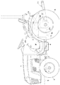
図6〜図9に、前記PTOクラッチ27の操作構造が示されている。 The operation structure of the PTO clutch 27 is shown in FIGS.
PTOクラッチ27のクラッチ部材34は、ミッドケース3mの側壁にフォーク支軸45を介して揺動可能に装着されたシフトフォーク46に係合されており、運転部横側に支持ブラケット47を介して前後揺動可能に立設配備されたクラッチレバー48と前記フォーク支軸45の外端部とがリンク機構50を介して連動連結されている。
The
リンク機構50は、前記支持ブラケット47に揺動自在に枢支連結された操作アーム51、フォーク支軸45の外端に連結固定したクラッチアーム52、操作アーム51の遊端とクラッチアーム52の遊端とを連結するリンクロッド53、および、クラッチレバー48と操作アーム51とを連動連結するトグルリンク54とで構成されており、クラッチレバーが前方のクラッチ入り操作位置(ON)に操作されることで、クラッチ部材34が前方にシフトされて「クラッチ入り」状態がもたらされ、クラッチレバー48が後方のクラッチ切り操作位(0FF)に操作されることで、クラッチ部材34が後方にシフトされて「クラッチ切り」でかつPTOブレーキ35が制動作動された状態がもたらされるようになっている。
The
前記トグルリンク54は、クラッチレバー48がクラッチ入り操作位置(ON)とクラッチ切り操作位置(0FF)に亘って死点を越えて切り換え移動されるレバー保持手段としての機能を備えている。つまり、クラッチレバー48がクラッチ入り操作位置(ON)から後方に操作されると、トグルリンク54の上部支点pがクラッチレバー48の支点qを中心とする円弧軌跡で後方に移動し、これに対してトグルリンク54の下部支点rは操作アーム51の支点sを中心とする円弧軌跡で下方に変位し、これによって操作アーム51が下方揺動されてクラッチ部材34が後方(クラッチ切り方向)に移動してゆく。
The
トグルリンク54の下部支点rがトグルリンク54の上部支点pとクラッチレバー48の支点qとを結ぶ仮想線(死点)Lに到達した時点で操作アーム51は最も下方揺動された状態となり、この時、PTOクラッチ27は完全に切られて、圧縮変形されたコイルバネ38を介してPTOブレーキ35が押圧された制動状態にある。クラッチレバー48を更に後方に揺動して操作アーム51の基端ボス51aに接当する操作限界位置まで移動させると、図7に示すように、トグルリンク54の下部支点rがトグルリンク54の上部支点pとクラッチレバー48の支点qとを結ぶ仮想線Lを前方少し越えることになる。この状態では、圧縮変形状態にあるコイルバネ38の弾性復元力によってクラッチ部材34は前方にスライド付勢される。クラッチ部材34に作用する前方付勢力でクラッチアーム52が上方に揺動付勢され、クラッチアーム52に連動連結された操作アーム51も上方に揺動付勢される。これによって、トグルリンク54の下部支点rが死点Lより前方で上方に突き上げられて、クラッチレバー48は後方に揺動付勢され、もって、クラッチレバー48がクラッチ切り操作位置(0FF)に保持されるのである。
When the lower fulcrum r of the
なお、前記支持ブラケット47には操作アーム51が下方操作されてクラッチ切り位置にあることを検知するリミットスイッチ56が装着されており、PTOクラッチ27が切られていることがリミットスイッチ56で検知している状態でのみエンジン1の始動が可能となるよう、リミットスイッチ56がエンジン始動回路に接続されている。
The
前記フォーク軸45の外方突出部にはディスク57が固着されるとともに、このディスク57の外周に形成したノッチ58にバネ付勢されたデテントボール59を係合させるデテント機構60が装備されている。このデテント機構60は、クラッチ部材34がクラッチ入り位置にある時に係合作動して、クラッチ入り状態が安定保持されるようになっている。なお、デテントボール59を支持したホルダ61の基板61aがフォーク軸45の外周溝62に係合されて、フォーク軸45の抜け止め部材として利用されている。
A
〔他の実施例〕
(1)レバー保持手段としては、湾曲した死点越え用のトグルリンク53を利用したもので構成することもできる。
[Other Examples]
(1) The lever holding means may be configured by using a
3 ミッションケース
26 一方向クラッチ
27 PTOクラッチ
35 PTOブレーキ
34 クラッチ部材
38 コイルバネ
40 PTOモード選択機構
45 フォーク支軸
47 支持ブラケット
48 クラッチレバー
50 リンク機構
51 操作アーム
54 トグルリンク
L 仮想線
p 上部支点(クラッチレバー側の連結支点)
q 支点(レバー支点)
r 下部支点(操作アーム側の連結支点)
s 支点(アーム支点)
3
45
q fulcrum (lever fulcrum)
r Lower fulcrum (connection fulcrum on the operating arm side)
s Support point (arm support point)
Claims (5)
前記クラッチ部材をシフト操作するためのフォーク支軸をミッションケースの側壁に貫通支持するとともに、人為操作されるクラッチレバーをミッションケースの外面に固定された支持ブラケットに横向きのレバー支点周りで前後揺動自在に支持し、前記クラッチ部材を前記クラッチレバーによって変位操作可能となるように、ミッションケースの外部に延出された前記フォーク支軸の外端部と、前記フォーク支軸よりも機体後方側箇所に前記支持ブラケットを介して立設配備された前記クラッチレバーとをリンク機構を介して連動連結し、
前記リンク機構を構成するもので前端側が前記フォーク支軸の外端部にリンク連係された操作アームを、側面視で前記クラッチレバーと交差する前後向きの姿勢で配置して、その後端側を前記支持ブラケットに横向きのアーム支点周りで揺動自在に支持し、
前記クラッチレバーと前記操作アームとを前記リンク機構を構成するトグルリンクで連動連結し、前記クラッチレバーをクラッチ切り操作位置に揺動操作すると、前記PTOブレーキの制動操作に伴う前記コイルバネの反力によって前記クラッチ部材に作用するクラッチ入り方向への戻り付勢力が、前記トグルリンクにより前記クラッチレバーをクラッチ切り方向に作動させる力として作用して、前記クラッチレバーがクラッチ切り操作位置に固定保持されるよう構成してあることを特徴とする作業機のPTOクラッチ操作構造。 In the transmission case, equipped with a PTO clutch provided with a clutch member, a PTO brake provided on the lower transmission side of the PTO clutch , and a coil spring interposed between the clutch member and the PTO brake , in PTO clutch operation structure of the working machine that is configured to brake operating the PTO brake via the coil spring in conjunction with clutch disengaging operation of the clutch member,
The fork support shaft for shifting the clutch member is supported by penetrating the side wall of the transmission case, and the manually operated clutch lever is swung back and forth around the side lever support point on the support bracket fixed to the outer surface of the transmission case. An outer end portion of the fork support shaft that is extended to the outside of the transmission case so that the clutch member can be displaced by the clutch lever. The clutch lever that is erected and installed via the support bracket is interlocked and connected via a link mechanism,
An operation arm that constitutes the link mechanism and whose front end is linked to the outer end of the fork support shaft is disposed in a front-rear orientation that intersects the clutch lever in a side view, and the rear end is The support bracket is swingably supported around a lateral arm fulcrum,
When the clutch lever and the operation arm are interlocked and connected by a toggle link constituting the link mechanism, and the clutch lever is swung to the clutch disengagement operation position, the reaction force of the coil spring accompanying the braking operation of the PTO brake The return biasing force in the clutch engagement direction acting on the clutch member acts as a force for operating the clutch lever in the clutch disengagement direction by the toggle link, so that the clutch lever is fixedly held at the clutch disengagement operation position. A PTO clutch operating structure for a working machine, characterized in that it is configured.
Priority Applications (4)
| Application Number | Priority Date | Filing Date | Title |
|---|---|---|---|
| JP2006097738A JP4820198B2 (en) | 2006-03-31 | 2006-03-31 | PTO clutch operation structure for work equipment |
| US11/708,648 US7854281B2 (en) | 2006-03-30 | 2007-02-20 | PTO clutch for work vehicle and operating apparatus for same |
| KR1020070019296A KR100814524B1 (en) | 2006-03-31 | 2007-02-27 | Pto clutch operating structure for work vehicle |
| FR0753677A FR2899297B1 (en) | 2006-03-31 | 2007-03-06 | PTO CLUTCH FOR A WORKING VEHICLE AND ACTUATING APPARATUS THEREFOR. |
Applications Claiming Priority (1)
| Application Number | Priority Date | Filing Date | Title |
|---|---|---|---|
| JP2006097738A JP4820198B2 (en) | 2006-03-31 | 2006-03-31 | PTO clutch operation structure for work equipment |
Publications (2)
| Publication Number | Publication Date |
|---|---|
| JP2007270975A JP2007270975A (en) | 2007-10-18 |
| JP4820198B2 true JP4820198B2 (en) | 2011-11-24 |
Family
ID=38521380
Family Applications (1)
| Application Number | Title | Priority Date | Filing Date |
|---|---|---|---|
| JP2006097738A Active JP4820198B2 (en) | 2006-03-30 | 2006-03-31 | PTO clutch operation structure for work equipment |
Country Status (3)
| Country | Link |
|---|---|
| JP (1) | JP4820198B2 (en) |
| KR (1) | KR100814524B1 (en) |
| FR (1) | FR2899297B1 (en) |
Families Citing this family (3)
| Publication number | Priority date | Publication date | Assignee | Title |
|---|---|---|---|---|
| JP5142827B2 (en) * | 2008-05-29 | 2013-02-13 | ヤンマー株式会社 | Work vehicle |
| JP5592846B2 (en) * | 2011-07-12 | 2014-09-17 | 株式会社クボタ | Tractor |
| SE538385C2 (en) * | 2013-01-28 | 2016-06-07 | Scania Cv Ab | Retarder coupling device, vehicles including such coupling device and method for coupling a retarder |
Family Cites Families (9)
| Publication number | Priority date | Publication date | Assignee | Title |
|---|---|---|---|---|
| JP3161903B2 (en) * | 1994-04-08 | 2001-04-25 | 株式会社クボタ | Tractor power take-out structure |
| JP3450100B2 (en) * | 1995-08-15 | 2003-09-22 | 株式会社三協精機製作所 | Gear clutch mechanism |
| JP4666743B2 (en) * | 2000-10-20 | 2011-04-06 | ヤンマー株式会社 | transmission |
| JP4882190B2 (en) * | 2001-09-13 | 2012-02-22 | 井関農機株式会社 | Tractor |
| JP4475926B2 (en) | 2003-11-14 | 2010-06-09 | 株式会社クボタ | PTO shaft drive structure of tractor |
| JP4104149B2 (en) * | 2004-03-22 | 2008-06-18 | 株式会社クボタ | Tractor PTO transmission structure |
| KR100602527B1 (en) * | 2004-03-22 | 2006-07-20 | 가부시끼 가이샤 구보다 | Transmission system for tractor |
| JP4301062B2 (en) * | 2004-04-09 | 2009-07-22 | 井関農機株式会社 | Work vehicle having toroidal transmission |
| JP4362426B2 (en) | 2004-09-15 | 2009-11-11 | 株式会社クボタ | Work vehicle transmission structure |
-
2006
- 2006-03-31 JP JP2006097738A patent/JP4820198B2/en active Active
-
2007
- 2007-02-27 KR KR1020070019296A patent/KR100814524B1/en active IP Right Grant
- 2007-03-06 FR FR0753677A patent/FR2899297B1/en active Active
Also Published As
| Publication number | Publication date |
|---|---|
| JP2007270975A (en) | 2007-10-18 |
| KR100814524B1 (en) | 2008-03-17 |
| FR2899297B1 (en) | 2015-10-09 |
| KR20070098493A (en) | 2007-10-05 |
| FR2899297A1 (en) | 2007-10-05 |
Similar Documents
| Publication | Publication Date | Title |
|---|---|---|
| US7854281B2 (en) | PTO clutch for work vehicle and operating apparatus for same | |
| KR100693977B1 (en) | Pto operating structure of tractor | |
| JP4758800B2 (en) | Tractor PTO transmission structure | |
| JP4820198B2 (en) | PTO clutch operation structure for work equipment | |
| JP2006011843A (en) | Tractor operating structure | |
| JP4104149B2 (en) | Tractor PTO transmission structure | |
| JP4104148B2 (en) | Tractor transmission structure | |
| JP5167224B2 (en) | Gear switching device | |
| JP3161903B2 (en) | Tractor power take-out structure | |
| WO2011034167A1 (en) | Riding-type work machine | |
| JP2011031661A (en) | Working vehicle | |
| JP4420786B2 (en) | PTO operation structure of tractor | |
| JP2009047044A (en) | Travel control mechanism | |
| JP5592846B2 (en) | Tractor | |
| JP3727218B2 (en) | Tractor transmission structure | |
| JP4528006B2 (en) | Four-wheel drive tractor travel device | |
| JPS621473Y2 (en) | ||
| JP5083497B2 (en) | Tractor | |
| JP3541160B2 (en) | Agricultural work equipment steering device | |
| JP4519503B2 (en) | Four-wheel drive / front-wheel acceleration drive switching mechanism | |
| JP3895117B2 (en) | Working vehicle | |
| JP3672474B2 (en) | Agricultural machinery steering device | |
| JP2003226231A (en) | Parking brake device for working vehicle | |
| JP3662157B2 (en) | Agricultural machinery steering device | |
| JP5037426B2 (en) | Work vehicle |
Legal Events
| Date | Code | Title | Description |
|---|---|---|---|
| A621 | Written request for application examination |
Free format text: JAPANESE INTERMEDIATE CODE: A621 Effective date: 20080317 |
|
| A977 | Report on retrieval |
Free format text: JAPANESE INTERMEDIATE CODE: A971007 Effective date: 20101110 |
|
| A131 | Notification of reasons for refusal |
Free format text: JAPANESE INTERMEDIATE CODE: A131 Effective date: 20101118 |
|
| A521 | Written amendment |
Free format text: JAPANESE INTERMEDIATE CODE: A523 Effective date: 20110117 |
|
| A02 | Decision of refusal |
Free format text: JAPANESE INTERMEDIATE CODE: A02 Effective date: 20110331 |
|
| A521 | Written amendment |
Free format text: JAPANESE INTERMEDIATE CODE: A523 Effective date: 20110606 |
|
| A521 | Written amendment |
Free format text: JAPANESE INTERMEDIATE CODE: A821 Effective date: 20110606 |
|
| A911 | Transfer to examiner for re-examination before appeal (zenchi) |
Free format text: JAPANESE INTERMEDIATE CODE: A911 Effective date: 20110627 |
|
| TRDD | Decision of grant or rejection written | ||
| A01 | Written decision to grant a patent or to grant a registration (utility model) |
Free format text: JAPANESE INTERMEDIATE CODE: A01 Effective date: 20110804 |
|
| A01 | Written decision to grant a patent or to grant a registration (utility model) |
Free format text: JAPANESE INTERMEDIATE CODE: A01 |
|
| A61 | First payment of annual fees (during grant procedure) |
Free format text: JAPANESE INTERMEDIATE CODE: A61 Effective date: 20110902 |
|
| FPAY | Renewal fee payment (event date is renewal date of database) |
Free format text: PAYMENT UNTIL: 20140909 Year of fee payment: 3 |
|
| R150 | Certificate of patent or registration of utility model |
Ref document number: 4820198 Country of ref document: JP Free format text: JAPANESE INTERMEDIATE CODE: R150 Free format text: JAPANESE INTERMEDIATE CODE: R150 |