JP4820108B2 - Semiconductor wafer manufacturing method, workpiece slicing method, and wire saw used therefor - Google Patents
Semiconductor wafer manufacturing method, workpiece slicing method, and wire saw used therefor Download PDFInfo
- Publication number
- JP4820108B2 JP4820108B2 JP2005125989A JP2005125989A JP4820108B2 JP 4820108 B2 JP4820108 B2 JP 4820108B2 JP 2005125989 A JP2005125989 A JP 2005125989A JP 2005125989 A JP2005125989 A JP 2005125989A JP 4820108 B2 JP4820108 B2 JP 4820108B2
- Authority
- JP
- Japan
- Prior art keywords
- wire
- wafer
- polishing
- grinding
- workpiece
- Prior art date
- Legal status (The legal status is an assumption and is not a legal conclusion. Google has not performed a legal analysis and makes no representation as to the accuracy of the status listed.)
- Active
Links
Images


Classifications
-
- B—PERFORMING OPERATIONS; TRANSPORTING
- B28—WORKING CEMENT, CLAY, OR STONE
- B28D—WORKING STONE OR STONE-LIKE MATERIALS
- B28D5/00—Fine working of gems, jewels, crystals, e.g. of semiconductor material; apparatus or devices therefor
- B28D5/04—Fine working of gems, jewels, crystals, e.g. of semiconductor material; apparatus or devices therefor by tools other than rotary type, e.g. reciprocating tools
- B28D5/045—Fine working of gems, jewels, crystals, e.g. of semiconductor material; apparatus or devices therefor by tools other than rotary type, e.g. reciprocating tools by cutting with wires or closed-loop blades
-
- H—ELECTRICITY
- H01—ELECTRIC ELEMENTS
- H01L—SEMICONDUCTOR DEVICES NOT COVERED BY CLASS H10
- H01L21/00—Processes or apparatus adapted for the manufacture or treatment of semiconductor or solid state devices or of parts thereof
- H01L21/02—Manufacture or treatment of semiconductor devices or of parts thereof
- H01L21/04—Manufacture or treatment of semiconductor devices or of parts thereof the devices having at least one potential-jump barrier or surface barrier, e.g. PN junction, depletion layer or carrier concentration layer
- H01L21/18—Manufacture or treatment of semiconductor devices or of parts thereof the devices having at least one potential-jump barrier or surface barrier, e.g. PN junction, depletion layer or carrier concentration layer the devices having semiconductor bodies comprising elements of Group IV of the Periodic System or AIIIBV compounds with or without impurities, e.g. doping materials
- H01L21/30—Treatment of semiconductor bodies using processes or apparatus not provided for in groups H01L21/20 - H01L21/26
-
- B—PERFORMING OPERATIONS; TRANSPORTING
- B23—MACHINE TOOLS; METAL-WORKING NOT OTHERWISE PROVIDED FOR
- B23D—PLANING; SLOTTING; SHEARING; BROACHING; SAWING; FILING; SCRAPING; LIKE OPERATIONS FOR WORKING METAL BY REMOVING MATERIAL, NOT OTHERWISE PROVIDED FOR
- B23D57/00—Sawing machines or sawing devices not covered by one of the preceding groups B23D45/00 - B23D55/00
- B23D57/003—Sawing machines or sawing devices working with saw wires, characterised only by constructional features of particular parts
- B23D57/0053—Sawing machines or sawing devices working with saw wires, characterised only by constructional features of particular parts of drives for saw wires; of wheel mountings; of wheels
Description
この発明は、半導体ウエーハの製造方法、および、ワークのスライス方法、ならびに、それらに用いられるワイヤソーに関する。 The present invention relates to a method for manufacturing a semiconductor wafer, a method for slicing a workpiece, and a wire saw used therefor.
従来、半導体ウエーハ(以下、ウエーハという)は、図10のフローチャートに示す製造プロセスにより製造される。図10に示すように、最初のステップS202はスライス工程である。すなわち、ステップS202において、たとえば、単結晶引上げ法によって製造された単結晶インゴットの外周研削を行った後、結晶方向の位置決めのための、たとえば、オリエンテーションフラット加工やノッチ加工を施して、内周刃式ブレードソーまたはワイヤソーにより単結晶インゴットをスライシングする。次に、ステップS204は面取り工程である。ステップS204で、研磨砥石により、スライスされたウエーハの外周部を面取り(ベベリング)加工が施される。
ステップS206はラッピング工程または両頭研削工程である。ステップS206で、ラッピング工程または両頭研削工程により均一な厚みにするとともに、スライスによって発生したウエーハのうねりを除去する。
その後のステップS208は研削工程である。このステップS208で、研削砥石によりウエーハの表面を片面毎に、または、両面を同時に研削(グラインディング)してウエーハの両面を平坦化する。
ステップS210は研磨工程である。CMP(化学的機械的研磨:Chemical Mechanical Polishing)などの研磨によってウエーハの両面を鏡面加工する。
Conventionally, a semiconductor wafer (hereinafter referred to as a wafer) is manufactured by a manufacturing process shown in the flowchart of FIG. As shown in FIG. 10, the first step S202 is a slicing process. That is, in step S202, for example, after performing outer peripheral grinding of a single crystal ingot manufactured by a single crystal pulling method, for example, orientation flat processing or notch processing for positioning in the crystal direction is performed, and the inner peripheral blade Slicing the single crystal ingot with a type blade saw or wire saw. Next, step S204 is a chamfering process. In step S204, the outer peripheral portion of the sliced wafer is chamfered (beveled) with a polishing grindstone.
Step S206 is a lapping process or a double-head grinding process. In step S206, a uniform thickness is obtained by a lapping process or a double-head grinding process, and the waviness of the wafer generated by slicing is removed.
Subsequent step S208 is a grinding process. In this step S208, the surface of the wafer is ground on one side or both sides simultaneously (grinding) with a grinding wheel to flatten both sides of the wafer.
Step S210 is a polishing process. Both surfaces of the wafer are mirror-finished by polishing such as CMP (Chemical Mechanical Polishing).
従来においては、前記した工程によりウエーハを製造していたが、単結晶インゴットからウエーハを製造するまでの工程数が、前記のように多いことから、ウエーハの製造工程を簡略化することが求められていた。このような事情から、これらの工程の中のラッピング工程または両頭研削工程を省略することを検討した。 Conventionally, a wafer was manufactured by the above-described process, but since the number of processes from manufacturing a single crystal ingot to a wafer is large as described above, it is required to simplify the manufacturing process of the wafer. It was. Under such circumstances, it has been considered to omit the lapping process or the double-head grinding process in these processes.
しかしながら、通常の研削工程のみでは、ラッピング工程または両頭研削工程を行わないと、単結晶インゴットのスライス時に発生したウエーハの表面のうねりを除去することができない、という問題が残されていた。 However, there has been a problem that the waviness on the surface of the wafer generated during the slicing of the single crystal ingot cannot be removed unless the lapping process or the double-headed grinding process is performed only in the normal grinding process.
かかるこれらの問題を解決するために、特願平9−97775号公報(特許文献1参照)には、ラッピング工程または両頭研削工程を省略し、遊離砥粒を含んだ研磨材と硬い研磨布を使用して、ウエーハを両面から同時に研磨することによって、高い平坦度の加工ができると共に、スライスによって生じたウエーハの表面のうねりを除去する方法が記載されている。
また、特開2004−63883号公報(特許文献2参照)には、ラッピング工程または両頭研削工程を省略し、ウエーハの裏面をプラズマエッチングして、スライスによって生じたウエーハの表面のうねりを除去してから、ウエーハの表面を研削し、つづいてウエーハの表面を研磨することが記載されている。
Japanese Patent Application Laid-Open No. 2004-63883 (see Patent Document 2) omits the lapping step or the double-head grinding step, and plasma-etches the back surface of the wafer to remove waviness on the wafer surface caused by slicing. Thus, it is described that the surface of the wafer is ground and then the surface of the wafer is polished.
ところが、本発明者らが鋭意研究した結果、これらの解決方法では、うねりを完全に除去することができない、ということが分った。
それは、これまで、うねりを一つのものと捉えてきたが、実はうねりには、波長の短い短周期のうねりのほかに、波長の長い長周期のうねりがあり、うねりはこれらが合成されて形成されており、このうち、長周期のうねりを研磨工程によって除去することが難しいことが判明したからである。
なお、ここでいう長周期のうねりとは、波長がほぼ20mm以上をいい、短周期のうねりとは、波長がほぼ10mm以下をいう。
短周期のうねりであれば、ある程度の硬い研磨布を使用して平坦性を維持してうねりを除去することもできるが、長周期のうねりは、硬い研磨布であってもゆるやかな起伏のために研磨布の表面が長周期のうねりに沿ってしまい、その結果、研磨布ではうねりを除去できない、ということが分ったからである。
また、短周期のうねりについては、遊離砥粒を含んだ研磨材を使用して研磨布で研磨するCMP(特開平9−97775号公報)の場合には、硬い研磨布であっても、研磨布の硬さに上限があるため、短周期のうねりであっても除去することが難しいという問題があった。
However, as a result of intensive studies by the present inventors, it has been found that these solutions cannot completely remove the swell.
Up to now, swells have been regarded as one. Actually, in addition to short-wave swells with short wavelengths, swells have long-wave swells with long wavelengths. This is because it has been found that it is difficult to remove long-period waviness by a polishing process.
The long-period undulation referred to here means a wavelength of approximately 20 mm or more, and the short-period undulation refers to a wavelength of approximately 10 mm or less.
For short period waviness, it is possible to remove the waviness while maintaining flatness by using a certain degree of hard abrasive cloth, but long period waviness is due to gentle undulations even with a hard abrasive cloth. In other words, it was found that the surface of the polishing cloth was along a long period of waviness, and as a result, waviness could not be removed with the polishing cloth.
For short-period waviness, in the case of CMP (Japanese Patent Laid-Open No. 9-97775) in which polishing is performed with a polishing cloth using a polishing material containing loose abrasive grains, polishing is performed even with a hard polishing cloth. Since there is an upper limit on the hardness of the cloth, there is a problem that it is difficult to remove even a short period of waviness.
また、上記問題とは別に、近年、ウエーハの径サイズが従来の8インチ(以下、8″という)から12インチ(以下、12″という)へ移行しはじめている。たとえば、DRAMの世代交代は、256M(メガビット)から1G(ギガビット)へ移行しており、一段と微細加工、高集積化が進められている。こうしたニーズによる半導体ウエーハの大口径化は、大幅なコストダウンを可能にするが、その反対に、この半導体ウエーハに対する加工品質は、一段と厳しい形状精度が要求されている。従来の高平坦度の形状精度は、TTV(Total Thickness Variation)のウエーハ全面の厚さバラツキであったが、新たな平坦度の形状精度は、サイト平坦度SFQR(Site,Frontsurface,site least sQuares,Range)で評価され、今、この値が厳しくなってきている。
さらに、従来、問題視されなかった微少の長周期のうねり(ナノトポロジー:nanotopology)が、12″(300mm)サイズのウエーハから問題視されはじめ、この微少の長周期のうねりをとることが、新たなネック技術となっている。
In addition to the above problems, in recent years, the diameter of wafers has started to shift from 8 inches (hereinafter referred to as 8 ″) to 12 inches (hereinafter referred to as 12 ″). For example, the generation change of DRAM has shifted from 256M (megabits) to 1G (gigabits), and finer processing and higher integration are being promoted. Increasing the diameter of a semiconductor wafer due to these needs enables a significant cost reduction, but on the contrary, the processing quality for this semiconductor wafer requires a stricter shape accuracy. Previously, the shape accuracy of high flatness was the thickness variation of the entire surface of the TTV (Total Thickness Variation) wafer, but the new flatness shape accuracy is This value is getting stricter now.
Furthermore, a minute long-period undulation (nanotopology), which has not been regarded as a problem in the past, has started to be regarded as a problem from a wafer of 12 ″ (300 mm) size. It becomes a serious neck technology.
そこで、本発明は、これらの問題点に鑑み創案したものであり、ワイヤソーによるスライス工程で、ウエーハの表面に長周期のうねりを発生させないようにスライスするとともに、スライスされたウエーハ表面に残る短周期のうねりを研磨工程で完全に除去することでラッピング工程または両頭研削工程を省略できる半導体ウエーハの製造方法を提供することを課題とする。 Therefore, the present invention has been devised in view of these problems, and in the slicing process with a wire saw, the wafer surface is sliced so as not to generate long-period undulations, and the short period remaining on the sliced wafer surface remains. It is an object of the present invention to provide a method for manufacturing a semiconductor wafer in which the lapping process or the double-head grinding process can be omitted by completely removing the undulation in the polishing process.
本発明者らは、まず、長周期のうねりを除去するには、ワイヤソーによって行うしかないと考えた。そこで、ワイヤソーによるスライスによって、ウエーハの表面にうねりを発生させないようにするために、ワイヤソーの改良を検討した。これまでにも、たとえば、特開平11−58210号公報(特許文献3参照)のように、ウエーハの厚さむらや反りを低減するために、ワークのスライス開始からスライス終了までの間で、ワーク送り量や前記スラリーの供給量を調整したり、ワイヤ往復走行1サイクル当たりのワーク送り量を変化させたり、特開2000−141201号公報(特許文献4参照)のように、スライス面のうねりや表面あらさを抑えるためにワークスライス面の弦の長さに応じて、ワイヤ新線供給量やサイクル数またはサイクル周期を制御するなどの、スライス方法が試みられてきた。
しかし、これらはすべてのうねりや厚さむら等をワイヤソーによって除去しようとしたため、肝心の長周期のうねりを除去することができなかった。
The inventors of the present invention first thought that a long-period waviness could only be removed with a wire saw. Therefore, in order to prevent waviness on the wafer surface by slicing with a wire saw, an improvement of the wire saw was studied. In the past, for example, as disclosed in Japanese Patent Application Laid-Open No. 11-58210 (see Patent Document 3), in order to reduce the thickness unevenness and warpage of the wafer, the workpiece has been Adjusting the feed amount and the supply amount of the slurry, changing the work feed amount per cycle of wire reciprocation, and slicing the slicing surface as disclosed in JP 2000-141201 A (see Patent Document 4) In order to suppress the surface roughness, a slicing method such as controlling the supply amount of new wire, the number of cycles, or the cycle period according to the chord length of the work slice surface has been tried.
However, since all of these undulations, thickness irregularities, and the like were to be removed with a wire saw, it was not possible to remove the long-term undulations that were essential.
本発明では、ワイヤソーによるスライス工程で、長周期のうねりのみを除去することを考えたため、本発明者らは、このワイヤ往復走行のサイクル数に着目し、サイクル数を増加させることによって、これまで、長周期のうねりとして発生していたうねりを短周期のうねりに変化させるという方法に思い至った。 In the present invention, in the slicing process using a wire saw, it was considered that only long-period undulations were removed, so the present inventors focused on the number of cycles of this wire reciprocation and increased the number of cycles so far. I came up with a method of changing the undulation that occurred as a long-period swell into a short-period swell.
これまで、ワイヤソーではワイヤ往復走行のサイクル数が通常1分間に1〜2サイクルであったが、ワイヤソーでワークをスライスする時に、1分間当たり3サイクル以上であれば、長周期のうねりとして発生していたうねりを短周期のうねりに変化させることができるということが分かった。
この理論によれば、3サイクル以上であれば、すべて当てはまると考えられるが、8サイクル以上にした場合、短周期のうねりは消去できても、従来通りの高速送りを維持するには、制御、サーボ系の追従性に問題があり、8サイクル以上にすることは、機械構成上不可能な範囲となるため、8サイクル未満とした。
このことに関しては特開2003−318138号公報(特許文献5参照)に、8サイクル以上の多サイクルのワイヤ往復走行のスライス方法により、うねりを解消することが可能であることが記載されているが、8サイクル以上では現実的な解決方法ではない。また、この特許文献5は、長周期のうねりのみを抑えることを意図していないので、本発明と本質を異にしている。
このような理由から、ワイヤソーでワークをスライスする時に、1分間当たり3サイクル以上、8サイクル未満の間の一定サイクルでワイヤを往復走行させながらワークをスライスするが、さらに、長周期のうねりだけでなく、短周期のうねりに関しても減少していることが分かった。
これは、これまで短周期のうねりだったものが、超短周期のうねりとなり、結果的にうねりとして観測されないレベルにまで短い周期のうねりとなるからである。
Until now, the number of cycles of wire reciprocation with a wire saw was normally 1 to 2 cycles per minute. However, when slicing a workpiece with a wire saw, if the number of cycles is 3 cycles or more per minute, a long period of undulation will occur. It was found that the swell that had been changed can be changed to a swell of a short period.
According to this theory, it is considered that all the cases are applicable when the number of cycles is 3 or more. However, when the number of cycles is 8 or more, even if the short-period undulation can be eliminated, the control, There is a problem in the followability of the servo system, and setting it to 8 cycles or more is an impossible range in terms of the machine configuration.
In this regard, Japanese Patent Application Laid-Open No. 2003-318138 (see Patent Document 5) describes that undulation can be eliminated by a multi-cycle slicing method of multi-cycle wire reciprocation of 8 cycles or more. , 8 cycles or more is not a realistic solution. Moreover, since this
For this reason, when slicing a workpiece with a wire saw, the workpiece is sliced while reciprocating the wire at a constant cycle of 3 cycles or more and less than 8 cycles per minute. It was also found that the short-period swell also decreased.
This is because what has been swelled with a short period until now becomes a swell with a very short period, resulting in a swell with a short period to a level that is not observed as a swell.
しかしながら、すべてのうねりを超短周期のうねりにすることは、1分間当たり3サイクル以上、8サイクル未満の間では不可能なため、短周期のうねりは、別途除去する必要がある。短周期のうねりは、ラッピング工程または両頭研削工程で除去することができるが、これらの工程を省略することが目的であるので、この工程を省略する場合、従来の研磨工程によって、研磨加工とともにうねりを除去することが望ましい。
研削工程でうねりを除去することも考えられるが、研削では、チャックテーブルにおいて研削する場合に、加工面と反対側のうねりが転写して加工されてしまうため、うねりを除去することはできない。また、特別な工夫をしない限り、研削でうねりを除去することはできない。
したがって、研磨加工でうねりを除去することになるが、研磨布と遊離砥粒との組み合わせで研磨を行う通常のCMP(化学的機械的研磨)では、使用する研磨布の硬度に限界がある。つまり、硬度が高いと、遊離砥粒が研磨布に滞留しないで流出してしまうので、研磨ができない、という問題があった。
よって、研磨布にはある程度の柔らかさが必要であるが、柔らかいと短周期のうねりに研磨布がそって撓んでしまい、研磨することができても、うねりを除去することはできなかった。
However, since it is impossible to make all the undulations have an ultra short period undulation between 3 cycles per minute and less than 8 cycles, the short period undulations need to be removed separately. Short period waviness can be removed in the lapping process or the double-head grinding process, but the purpose is to omit these processes. It is desirable to remove.
Although it is conceivable to remove the undulation in the grinding process, in the grinding, the undulation on the side opposite to the processing surface is transferred and processed when grinding on the chuck table. Therefore, the undulation cannot be removed. In addition, the waviness cannot be removed by grinding unless special measures are taken.
Therefore, the waviness is removed by the polishing process. However, in ordinary CMP (chemical mechanical polishing) in which polishing is performed with a combination of a polishing cloth and loose abrasive grains, the hardness of the polishing cloth to be used is limited. In other words, when the hardness is high, the loose abrasive particles flow out without staying on the polishing cloth, and there is a problem that polishing is impossible.
Therefore, the polishing cloth needs to have a certain degree of softness. However, if the polishing cloth is soft, the polishing cloth bends along a short period of waviness, and even if it can be polished, the waviness cannot be removed.
そこで、本発明者らは、固定砥粒研磨布を用いて、ワークの表面を研磨したところ、ウエーハ表面に残った短周期のうねりを完全に除去することができたのである。
また、ワークのスライス時、1分間当たり4〜6サイクルの間の一定サイクルでワイヤを往復走行させることにより、無理のない安定したスライス動作のもとで、そのうねりを抑える効果が顕著となる。
Therefore, the present inventors have been able to completely remove the short-period waviness remaining on the wafer surface when the surface of the workpiece is polished using a fixed abrasive polishing cloth.
Further, when the workpiece is sliced, by reciprocating the wire at a constant cycle of 4 to 6 cycles per minute, the effect of suppressing the undulation becomes remarkable under a stable and stable slicing operation.
請求項1に係る半導体ウエーハの製造方法の発明は、複数本の加工用ローラ間にワイヤ(14)を複数回、巻き回してワイヤ列を形成し、そのワイヤ(14)を往きより戻りを短く設定して往復走行させながら前記ワイヤ列とワーク(W)との間にスラリーを供給しつつワイヤ列にワーク(W)を相対的に押し付けて一度に複数枚のウエーハ(w)にスライスするワイヤソーによって、ワイヤ(14)の往復走行の1往復を1サイクルとすると、1分間当たり4サイクル以上6サイクル以下の間の一定サイクルでワイヤ(14)を往復走行させながらワーク(W)をスライスするスライス工程と、前記スライスされたウエーハ(w)の両面を研削砥石によって片面ずつ研削する研削工程と、前記研削されたウエーハ(w)の両面に対して、固定砥粒研磨布と砥粒を含まない研磨材を使用して化学的機械的研磨する研磨工程と、からなることを特徴とする。 According to the first aspect of the present invention, there is provided a method for manufacturing a semiconductor wafer, wherein a wire row is formed by winding a wire (14) a plurality of times between a plurality of processing rollers, and the return of the wire (14) is made shorter than going forward. A wire saw that slices into a plurality of wafers (w) at a time by relatively pushing the workpiece (W) against the wire row while supplying slurry between the wire row and the workpiece (W) while reciprocating and setting. Assuming that one reciprocation of the reciprocating movement of the wire (14) is one cycle, the slice for slicing the workpiece (W) while reciprocating the wire (14) at a constant cycle between 4 cycles and 6 cycles per minute A grinding process in which both sides of the sliced wafer (w) are ground one by one with a grinding wheel, and both sides of the ground wafer (w) are fixed. Wherein the polishing step of chemical mechanical polishing using an abrasive containing no abrasive grain polishing cloth and abrasive grains, in that it consists of.
請求項2に係る発明は、請求項1に記載の半導体ウエーハの製造方法であって、前記研削工程の後に、研削工程によって生じたウエーハ(w)の加工変質層を除去するためのエッチング工程と、ウエーハ(w)の外周縁を鏡面に仕上げる鏡面面取り工程とを行い、さらに、前記研磨工程の後に片面を鏡面に仕上げる片面仕上げ研磨工程を行うことを特徴とする。
The invention according to
請求項3に係る発明は、請求項1または請求項2に記載の半導体ウエーハの製造方法であって、多官能イソシアネートと、少なくとも平均分子量が250〜4,000の多官能ポリオールと、研磨パッドの発泡倍率が1.11〜5倍になるように発泡剤とを攪拌混合し、さらに、平均粒径0.15〜50μmの砥粒を5〜70体積%の範囲で混合させて形成されたポリウレタン研磨パッドであることを特徴とする。
Invention of Claim 3 is a manufacturing method of the semiconductor wafer of Claim 1 or
本発明によれば、半導体ウエーハの製造工程において、ラッピング工程または両頭研削工程を省略し、ワイヤソーでワークをスライスする時に、1分間当たり4サイクル以上6サイクル以下の間の一定サイクルでワイヤを往復走行させながらワークをスライスして、長周期のうねりを除去し、さらに、残った短周期のうねりを固定砥粒研磨布と、砥粒を含まない研磨液(アルカリ溶液)によって、スライスされたウエーハの表面に残る短周期のうねりを除去するので、半導体ウエーハの表面からうねりを完全に除去することができる。したがって、ラッピング工程または両頭研削工程を省略して、半導体ウエーハを製造することができる。 According to the present invention, in the semiconductor wafer manufacturing process, the lapping process or the double-head grinding process is omitted, and when the workpiece is sliced with a wire saw, the wire is reciprocated at a constant cycle of 4 cycles or more and 6 cycles or less per minute. The workpiece is sliced while removing the long-period waviness, and the remaining short-period waviness is further removed with a fixed abrasive polishing cloth and a polishing liquid (alkali solution) containing no abrasive grains. Since the short-period waviness remaining on the surface is removed, the waviness can be completely removed from the surface of the semiconductor wafer. Therefore, the semiconductor wafer can be manufactured by omitting the lapping process or the double-head grinding process.
本発明の実施の形態を、図面に基づいて詳細に説明する。
発明者は鋭意研究、実験を重ねた結果、前記した図1と同様の構成であるワイヤソーにおいて、ワークのスライス時、1分間に3往復以上、8往復未満の範囲で前記ワイヤの往復走行をさせることにより、スライス後のウエーハ表面に長周期のうねりがなくなることを確認した。まず、最初に、ワイヤソーから説明する。
図1はそのワイヤソーの主要部を示す斜視図である。図1に示すように、このワイヤソー1は、3本の加工用ローラ11,12,13が所定の間隔をおいて配設され、これらの各加工用ローラ11,12,13の外周にはそれぞれ多数の環状溝11a,12a,13aが所定ピッチで形成されている。そして、1本のワイヤ14は、一対のリール16,17に両端がそれぞれ巻き付けられている。そして、両リール16,17間において、ワイヤ14が加工用ローラ11,12,13の環状溝11a,12a,13a間に連続して巻回されている。
Embodiments of the present invention will be described in detail with reference to the drawings.
As a result of intensive studies and experiments, the inventor causes the wire to reciprocate within a range of 3 or more and less than 8 reciprocations per minute when the workpiece is sliced in the wire saw having the same configuration as that shown in FIG. Thus, it was confirmed that long-period waviness was eliminated on the wafer surface after slicing. First, the wire saw will be described first.
FIG. 1 is a perspective view showing the main part of the wire saw. As shown in FIG. 1, in this wire saw 1, three
ワイヤ送り手段は、加工用ローラ13に接続されたワイヤ走行用の主軸モータ18と、一対のリール16,17に接続されたリール用モータ19,20とにより構成されており、それらのモータの回転により、ワイヤ14は加工用ローラ11,12,13の正転側送りで、所定の送り量で送られた後に、ワイヤ14が加工用ローラ11,12,13の逆転側送りで、前記正転側の送り量よりも少ない送り量で送られる。この正転側送りと逆転側送りとが一送りサイクルとして繰り返し行われることにより、ワイヤ14が正転側へ前進する。そして、このワイヤ14の走行状態で、加工用ローラ11,12間のワイヤ14にワークWが押し付けられることにより、ワークWが所定の厚さをなすようにウエーハ状にスライスされる。
ワイヤソー1の切刃は、ワイヤ14に供給されるスラリーに混入された砥粒であり、このワイヤ14に擦られた砥粒によって、ワークWをラッピング作用で徐々に切断する。
なお、ワイヤ14の材質は鋼線であるが、ピアノ線であってもよい。
The wire feeding means includes a spindle motor 18 for wire travel connected to the processing roller 13 and
The cutting blade of the wire saw 1 is abrasive grains mixed in the slurry supplied to the wire 14, and the workpiece W is gradually cut by a lapping action by the abrasive grains rubbed against the wire 14.
In addition, although the material of the wire 14 is a steel wire, it may be a piano wire.
また、前記一対のリール16,17と加工用ローラ11,12,13との間のワイヤ14の走行経路中にはダンサアーム22,23が設けられ、それらの先端に配置されたダンサローラ22a,23aにはワイヤ14が掛けられている。そして、ワイヤ14の走行中に張力変動が発生したとき、ダンサアーム22,23が回動され、その回動量に基づいてエンコーダ24,25からワイヤ張力変動の検出信号が出力される。
なお、両ダンサアーム22,23は、それぞれウェイト代わりのダンサローラ22a,23aが機能しており、ワイヤ14に対して所定の張力を付与する。
また、ワイヤ送り制御手段を含む制御装置15は、ワイヤ送りのための設定値、たとえば、ワークの種類や材質に応じたワイヤ最高送り速度、新線供給量、往復走行サイクル数などに基づき、前記主軸モータ18および一対のリール用モータ19,20の回転数(回転速度)を制御するようになっている。さらに、前記エンコーダ24,25からの検出信号に応じて、前記リール用モータ19,20をフィードバック制御する。
Also,
The
Further, the
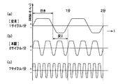
図2はワークのスライス時の時間に対するワイヤ速度の変化を示すサイクル線図であり、図2の(a)は従来例を示すサイクル線図、図2の(b)、(c)は本発明の例を示すサイクル線図である。図2の(a)に示すように、従来のワイヤ速度は、1分間当たり1サイクルであり、多くて2サイクルまでとなっている。
これに対して、図2の(b)の場合は、1分間当たり3サイクルであり、図2の(c)の場合は、1分間当たり7サイクルである。
なお、この波型(サイクルパターン)は、これ以外の曲線で形成されたものであってもよいし、また、最高速の送り速度を示す上端部、下端部の一定速度部分の長さを適宜設定変更しても構わない。
FIG. 2 is a cycle diagram showing a change in wire speed with respect to time at the time of slicing a workpiece. FIG. 2A is a cycle diagram showing a conventional example, and FIGS. 2B and 2C are diagrams showing the present invention. It is a cycle diagram which shows the example of. As shown in FIG. 2 (a), the conventional wire speed is 1 cycle per minute, up to 2 cycles.
On the other hand, in the case of FIG. 2B, there are 3 cycles per minute, and in the case of FIG. 2C, there are 7 cycles per minute.
In addition, this waveform (cycle pattern) may be formed by a curve other than this, and the lengths of the constant speed portions of the upper end portion and the lower end portion indicating the highest feed rate are appropriately set. You can change the setting.
このように、図1に示すワイヤ送り制御手段を含む制御装置15により、本発明のワークWのスライス方法が実行され、ワイヤ列にワークWを相対的に押し付けて複数枚にスライスするワイヤソー1において、ワイヤ14の往復走行の1往復を1サイクルとした場合、ワークWのスライス時、1分間当たり3サイクル以上8サイクル未満の間の、一定サイクルでワイヤ14を往復走行させながらワークWをスライスすると、長周期のうねりを抑え込むことができるため、その後工程の研削、研磨工程の負担が軽減でき、高品位のウエーハ(w)を作製することができる。
As described above, in the wire saw 1 that performs the slicing method of the workpiece W of the present invention by the
また、ワークのスライス時、1分間当たり4〜6サイクルの間の一定サイクルでワイヤ14を往復走行させることにより、無理のない安定したスライス動作のもとで、そのうねりを抑える効果が顕著であった。
さらに、ワイヤの往復走行の1往復を1サイクル中、600〜1500m/minのワイヤ14の最高走行速度で、同一ワークに対して最後まで同一サイクルパターンを繰り返すだけでよい。
この場合、図1における主軸モータ18を、その出力容量が45〜110kwの高容量のモータを使用することで、ワイヤ14の高速送りと、高サイクル数送りとに容易に対応することができた。
In addition, when slicing the workpiece, the wire 14 is reciprocated at a constant cycle of 4 to 6 cycles per minute, so that the effect of suppressing the undulation is remarkable under a stable and stable slicing operation. It was.
Furthermore, it is only necessary to repeat the same cycle pattern to the end of the same workpiece at the maximum traveling speed of the wire 14 in one cycle of one reciprocal movement of the wire during one cycle.
In this case, the spindle motor 18 in FIG. 1 can easily cope with high-speed feeding of the wire 14 and high-cycle number feeding by using a high-capacity motor having an output capacity of 45 to 110 kw. .
図3は本発明の実施の形態に係る半導体ウエーハの製造方法を示すフローチャートである。図3に示すように、本発明の半導体ウエーハの製造方法は、複数本の加工用ローラ間にワイヤ14を複数回巻き回してワイヤ列を形成し、そのワイヤ14を往きより戻りを短く設定して往復走行させながら前記ワイヤ列とワークWとの間にスラリーを供給し、ワイヤ列にワークWを相対的に押し付けて複数枚同時にスライスしてウエーハwにするスライス工程(S1)と、ウエーハwの外周縁を面取りする面取り工程(S2)と、ウエーハwの両面を研削する前記研削工程(S3)を行い、つぎに、前記エッチング工程(S4)を行った後、半導体ウエーハの外周縁を鏡面に仕上げる鏡面面取り工程(S5)を行い、つぎに、研磨工程において、固定砥粒研磨布9によるウエーハwの両面の一次研磨工程(S6)を行い、つづいて、片面を鏡面に仕上げる片面仕上げ研磨工程(S7)を行い、最後に洗浄をする洗浄工程(S8)の8工程により半導体ウエーハが作製される。以下、各工程順に詳細に説明する。
FIG. 3 is a flowchart showing a method for manufacturing a semiconductor wafer according to an embodiment of the present invention. As shown in FIG. 3, in the method for manufacturing a semiconductor wafer according to the present invention, a wire row is formed by winding a wire 14 a plurality of times between a plurality of processing rollers, and the return of the wire 14 is set to be shorter than the going. A slicing step (S1) for supplying slurry between the wire row and the workpiece W while reciprocating the workpiece W, relatively pressing the workpiece W against the wire row and simultaneously slicing a plurality of wafers into the wafer w, and the wafer w The chamfering step (S2) for chamfering the outer peripheral edge of the wafer and the grinding step (S3) for grinding both surfaces of the wafer w are performed, and then the etching step (S4) is performed. Then, a mirror chamfering step (S5) is performed, and then, in the polishing step, a primary polishing step (S6) on both sides of the wafer w by the fixed
シリコンインゴットは、石英ルツボを回転させながらシード(シリコン単結晶の小片)をシリコン融液から引き上げて12″以上の円柱状のインゴットに作製される(CZ法)。その後、両端部が切り落とされ、シリコンインゴットの外周が所定の径に加工される。
前記S1工程は、このシリコンインゴット(以下、ワークWという)のスライス(切断)工程であり、厚さ0.90mm(900μm)程度の12″のウエーハwにスライスされる。そこで、本発明のS1工程は、前記スライス工程でワイヤの往復走行の1往復を1サイクルとすると、1分間当たり3サイクル以上8サイクル未満の間の一定サイクルでワイヤを往復走行させながらワークをスライスする。
また、前記したスライス工程においては、1分間当たり4サイクル〜6サイクルの間の一定サイクルでワイヤ14を往復走行させることが好適である。
さらに、前記したスライス工程においては、ワイヤ14の往復走行の1サイクル中、ワイヤの最高走行速度が600〜1500m/minが好適であり、スライス中、同一のワークWに対して同一サイクルパターンを繰り返すとよい。
A silicon ingot is produced into a cylindrical ingot of 12 ″ or more by pulling a seed (a piece of silicon single crystal) from a silicon melt while rotating a quartz crucible (CZ method). Thereafter, both ends are cut off, The outer periphery of the silicon ingot is processed to a predetermined diameter.
The S1 step is a slicing (cutting) step of this silicon ingot (hereinafter referred to as a work W), and is sliced into a 12 ″ wafer w having a thickness of about 0.90 mm (900 μm). In the slicing step, assuming that one reciprocation of the wire reciprocating in the slicing step is one cycle, the work is sliced while reciprocating the wire at a constant cycle of 3 cycles or more and less than 8 cycles per minute.
In the slicing step described above, it is preferable to reciprocate the wire 14 at a constant cycle of 4 to 6 cycles per minute.
Further, in the above-described slicing step, the maximum traveling speed of the wire is preferably 600 to 1500 m / min during one cycle of the reciprocating traveling of the wire 14, and the same cycle pattern is repeated for the same workpiece W during the slicing. Good.
前記S2工程は、このウエーハwに面取り加工が施される。このウエーハwの外周部は、#600番と#1500番のメタル面取り用砥石により、所定の形状に面取りされ、所定の丸みを帯びた形状に成形される。 In the step S2, the wafer w is chamfered. The outer peripheral portion of the wafer w is chamfered into a predetermined shape by a # 600 and # 1500 metal chamfering grindstone, and is formed into a predetermined rounded shape.
前記S3工程は、仕上げ研削工程であり、ウエーハが研削される。この工程では、ウエーハの平坦度を得るための平坦面を形成するだけの研削で充分である。微細粒度の砥石によりウエーハ表裏両面を機械的に研削加工を行う。この際の研削量は、ウエーハwの表裏両面を合わせて約60μmである。具体的には、#2000番のレジノイド研削砥石を搭載した研削装置により、片面ずつ表面研削し、両面を研削する。 The step S3 is a finish grinding step, in which the wafer is ground. In this step, it is sufficient to grind only to form a flat surface for obtaining the flatness of the wafer. Both the front and back of the wafer are mechanically ground with a fine-grain grindstone. The amount of grinding at this time is about 60 μm including both the front and back surfaces of the wafer w. Specifically, surface grinding is performed on each side using a grinding machine equipped with a # 2000 resinoid grinding wheel, and both sides are ground.
この研削工程では、ウエーハの表面と裏面を各々順番に研削する。この研削方法は、図示しないが、ウエーハを保持するチャック手段を有する回転軸と、その回転軸と対向する回転軸の一端に装着される研削砥石からなり、研削砥石を高速回転させながら、ウエーハの研削面に押圧することにより研削する。ここで使用される研削砥石は、後工程の一次研磨工程の研磨量を減らすため、研削による加工変質層を極力浅くする、かつ、超平坦度を必要とするために、#1500以上の砥粒径を有する研削砥石を使用した方がよい。 In this grinding process, the front surface and the back surface of the wafer are ground in order. Although not shown, this grinding method includes a rotating shaft having chuck means for holding the wafer and a grinding wheel mounted on one end of the rotating shaft facing the rotating shaft. While rotating the grinding wheel at high speed, Grind by pressing on the grinding surface. The grinding wheel used here is # 1500 or more in order to reduce the amount of polishing in the primary polishing step in the subsequent process, to make the work-affected layer by grinding as shallow as possible and to require super flatness. It is better to use a grinding wheel having a diameter.
前記S4工程では、仕上げ研削工程で生じた歪みをとるためにエッチングが行なわれる。アルカリ性のエッチング液としては高濃度のKOH(水酸化カリウム)溶液が好適である。そのエッチング温度は90℃、エッチング時間は6分である。このときのエッチング量は、ウエーハ表裏両面合わせて10〜15μmである。 In the step S4, etching is performed in order to remove distortion generated in the finish grinding process. A highly concentrated KOH (potassium hydroxide) solution is suitable as the alkaline etching solution. The etching temperature is 90 ° C. and the etching time is 6 minutes. The etching amount at this time is 10 to 15 μm for both the front and back surfaces of the wafer.
前記S5工程では、面取り部分に鏡面研磨を施す鏡面面取り(PCR:Polishimg Conor Rounding)工程である。この鏡面面取り工程によって、ウエーハwの外周縁を磨き、鏡面に仕上げる。これにより、ウエーハwの強度を向上させ、パーティクルの発生を防ぎ、歩留まりの低下を防止できる。 The step S5 is a mirror chamfering (PCR: Polishimg Conor Rounding) step of performing mirror polishing on the chamfered portion. By this mirror chamfering process, the outer peripheral edge of the wafer w is polished and finished to a mirror surface. Thereby, the intensity | strength of the wafer w can be improved, generation | occurence | production of a particle can be prevented, and the fall of a yield can be prevented.
前記S6工程では、固定砥粒研磨布9を用いてウエーハwを両面鏡面研磨する両面研磨工程であり、つぎのS7工程の前加工である。ここでの仕上げ程度は、裏面の仕上げ程度に両面が仕上げられ、表面の厳しい超平坦度のSFQRの形状精度の要求をクリヤする。
The step S6 is a double-side polishing step in which the wafer w is mirror-polished on both sides using the fixed
図11は、両面研磨装置を示す全体斜視図であり、図12はその縦断面図である。この両面研磨工程では、例えば、図11、図12に示すような両面研磨装置100が用いられる。両面研磨装置100は、5個のウエーハ保持孔111aがプレート軸線回りに(円周方向に)72度ごとに穿設された平面視して円板形状のガラスエポキシ製のキャリアプレート111と、それぞれのウエーハ保持孔111aに旋回自在に挿入されて保持された12″(直径300mm)のウエーハwを、上下から挟み込むとともに、ウエーハwに対して相対的に移動させることでウエーハ面を研磨する上定盤112および下定盤113とを備えている。
FIG. 11 is an overall perspective view showing a double-side polishing apparatus, and FIG. 12 is a longitudinal sectional view thereof. In this double-side polishing step, for example, a double-
固定砥粒研磨布9は、多官能イソシアネートと、少なくとも平均分子量が250〜4,000の多官能ポリオールと、研磨パッドの発泡倍率が1.11〜5倍になるように発泡剤とを攪拌混合し、さらに平均粒径0.15〜50μmの砥粒を5〜70体積%の範囲で混合させて形成されたポリウレタン研磨パッドである。
The fixed
前記S7工程では、前工程のS6工程の後、スウェーブタイプの仕上げ研磨布によりウエーハwの片面の表面を鏡面(ミラーポリッシュ)に研磨仕上げをする。 In the step S7, after the previous step S6, the surface of one surface of the wafer w is polished to a mirror surface (mirror polish) with a swave type finish polishing cloth.
前記S8工程では、このウエーハwに洗浄工程を施す。具体的には、RCA(アンモニア過酸化水素水)系の洗浄水で洗浄を行う。 In the step S8, a cleaning process is performed on the wafer w. Specifically, cleaning is performed with RCA (ammonia hydrogen peroxide) cleaning water.
これにより、ワイヤソーによるスライス工程後に従来のラップや両頭研削工程を省き、後工程では規格内の平坦度(以下、TTVという)を得るための平坦面を形成するだけの取りしろでよく、さらに、仕上げの研磨工程で短周期のうねりを簡単にとることにより、半導体ウエーハの製造工程の短縮ができる。 As a result, the conventional lapping and double-head grinding processes are omitted after the slicing process with a wire saw, and in the subsequent process, it is only necessary to form a flat surface for obtaining flatness within the standard (hereinafter referred to as TTV). The semiconductor wafer manufacturing process can be shortened by simply taking a short period of waviness in the final polishing process.
図4は12″のウエーハの表面に現われるうねりを示し、図4の(a)は短周期と長周期を合成したうねり、図4の(b)は長周期のうねりを示すグラフである。図4の(a)に示すように、短周期のうねりの波長(L1)は、約8mmであり、これが図4の(b)に示す長周期のうねりの波形に乗っているのが分かる。長周期のうねりは、図4の(b)に示すように、波長(L2)が約40mmであり、短周期のうねりをとっても、長周期のうねりが残り、この長周期のうねりを仕上げ工程でとることは困難であるとされている。 FIG. 4 shows the undulations appearing on the surface of a 12 ″ wafer, FIG. 4 (a) is a graph showing a combination of short and long periods, and FIG. 4 (b) is a graph showing long period undulations. As shown in FIG. 4 (a), the wavelength (L1) of the short-period undulation is about 8 mm, and it can be seen that this is on the waveform of the long-period undulation shown in (b) of FIG. As shown in FIG. 4B, the period waviness has a wavelength (L2) of about 40 mm. Even if a short period waviness is taken, a long period waviness remains, and this long period waviness is taken in the finishing process. It is said that it is difficult.
図5は12″のウエーハをスライスする従来の方法である1〜2サイクルのワイヤ往復走行によりスライスした場合のウエーハの表面状態を示し、図5の(a)は、仕上げ研削後に撮影した長周期、短周期のうねりが残った状態を示す平面図、図5の(b)は、さらに研磨した後に撮影した長周期のうねりが残った状態を示す平面図である。
図5の(a)に示すように、従来のワークのスライス方法では、長周期のうねりの発生を抑えることができず、長周期、短周期のうねりを有するウエーハwにスライスされていることが分かる。また、図5の(b)に示すように、研磨後のウエーハwの表面には、これまで問題にならなかった長周期のうねりが確認された。
FIG. 5 shows the surface state of the wafer when sliced by reciprocating wire in one or two cycles, which is a conventional method for slicing a 12 ″ wafer. FIG. 5A shows a long period taken after finish grinding. FIG. 5B is a plan view showing a state in which a long-period swell imaged after further polishing is left.
As shown in FIG. 5A, in the conventional method for slicing a workpiece, the occurrence of long-period waviness cannot be suppressed, and it is sliced into a wafer w having long-period and short-period waviness. I understand. Further, as shown in FIG. 5B, long-period waviness that had not been a problem until now was confirmed on the surface of the polished wafer w.
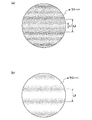
図6は12″のウエーハをスライスする本発明の方法である3サイクルのワイヤ往復走行によりスライスした場合のウエーハの表面状態を示し、図6の(a)は、仕上げ研削後に撮影した短周期のうねりのみが残った状態を示す平面図、図6の(b)は、さらに研磨した後に撮影した表面状態を示す平面図である。
図6の(a)に示すように、本発明のワークのスライス方法においてスライスされたウエーハwの表面には、短周期のうねりは認められるが、長周期のうねりの発生はなく、その証拠に、図6の(b)に示すように、研磨工程により短周期のうねりを消去した後には、長周期のうねりもない高品位なウエーハが完成した。4サイクル、5サイクル、6サイクル、7サイクルによるスライス実験においても、3サイクルと同様に、ウエーハwの表面には長周期のうねりは認められなかった。このスライス方法は、現在、8″から12″以上へ移行するこの移行期において、12″以上の高品位の半導体ウエーハの製造技術としては、画期的な技術となる。
FIG. 6 shows the surface state of the wafer when it is sliced by reciprocating three cycles of the wire, which is the method of the present invention for slicing a 12 ″ wafer. FIG. 6 (a) shows a short cycle imaged after finish grinding. FIG. 6B is a plan view showing a surface state taken after further polishing. FIG. 6B is a plan view showing a state in which only undulation remains.
As shown in FIG. 6 (a), the surface of the wafer w sliced by the workpiece slicing method of the present invention has short-period waviness but no long-period waviness. As shown in FIG. 6B, after erasing the short-period waviness by the polishing process, a high-quality wafer having no long-period waviness was completed. In the slicing experiments with 4, 5, 6, and 7 cycles, no long-period undulation was observed on the surface of the wafer w as in the case of 3 cycles. This slicing method is an epoch-making technique as a manufacturing technique of a high-quality semiconductor wafer of 12 ″ or more in this transition period where the current transition from 8 ″ to 12 ″ or more.
この実験によると、まず、短周期のうねりについては、ワイヤソーによるスライス工程において、ワイヤ往復走行を1分間当たり3サイクル、4サイクル、5サイクル、6サイクル、7サイクルの一定サイクルでスライスを行い、前記TTVを得るに可能な平坦面を形成させる研削と、エッチング後に、ポリウレタン研磨パッドの固定砥粒研磨布(具体的には特開2003−257905に記載された研磨パッド)を用いた研磨方法で研磨を行った結果、ウエーハの表面から短周期のうねりが完全に消えた。 According to this experiment, first, for the swell of a short cycle, in the slicing process with a wire saw, the wire reciprocating is sliced at a constant cycle of 3 cycles, 4 cycles, 5 cycles, 6 cycles, 7 cycles per minute, Polishing with a polishing method using a fixed abrasive polishing cloth (specifically, a polishing pad described in JP-A-2003-257905) of a polyurethane polishing pad after grinding to form a flat surface capable of obtaining a TTV and etching. As a result, short-wave undulations completely disappeared from the wafer surface.
図7は従来の不織布の研磨パッドと遊離砥粒を含むスラリー(研磨液)とを使用した研磨法を示し、図7の(a)は初期段階の断面拡大図、図7の(b)は最終段階の断面拡大図である。図7の(a)に示すように、不織布の研磨パッドである研磨布2の上には、遊離砥粒3含むスラリー4が供給され、そのスラリー4を介してウエーハwを研磨する研磨法である。
FIG. 7 shows a polishing method using a conventional non-woven fabric polishing pad and a slurry (polishing liquid) containing loose abrasive grains. FIG. 7 (a) is an enlarged sectional view of the initial stage, and FIG. It is a cross-sectional enlarged view of the final stage. As shown in FIG. 7 (a), a slurry 4 containing loose abrasive grains 3 is supplied onto a polishing
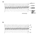
図8は前記S6工程に対応する固定砥粒研磨布を用いた研磨法を示し、図8の(a)は初期段階の断面拡大図、図8の(b)は中間段階の断面拡大図、図8の(c)は最終段階の断面拡大図である。
図9は固定砥粒研磨布の一例を示す拡大断面図である。
図9に示すように、固定砥粒研磨布9は、硬質のポリウレタン樹脂6であり、遊離砥粒3,3…はなく、すべての砥粒はポリウレタン樹脂6に固定されている。ポリウレタン樹脂6中に固定砥粒7,7…が混入されており、適量の気泡8,8…も形成されている。このポリウレタン研磨パッドの固定砥粒研磨布9は、多官能イソシアネートと、少なくとも平均分子量が250〜4,000の多官能ポリオールと、研磨パッドの発泡倍率が1.1〜5倍になるように発泡剤とを撹拌混合し、さらに平均粒径0.15〜50μmの砥粒を5〜70体積%の割合で加えたポリウレタン研磨パッドである。これを使用してアルカリ液を流しながら研磨工程を行う。
FIG. 8 shows a polishing method using a fixed abrasive polishing cloth corresponding to the step S6. FIG. 8A is an enlarged sectional view at an initial stage, and FIG. 8B is an enlarged sectional view at an intermediate stage. FIG. 8C is an enlarged sectional view of the final stage.
FIG. 9 is an enlarged cross-sectional view showing an example of a fixed abrasive polishing cloth.
As shown in FIG. 9, the fixed
図6の(a)のように表面に短周期のうねりが残っているウエーハwを従来の研磨法で研磨した場合、図7の(a)に示すように、不織布の研磨布2の硬度がシュアD硬度で5〜20と柔らかいため、遊離砥粒3を使用して研磨してもワークWの表面のうねりに沿って研磨布2が変形してしまう。そのため、図7の(b)に示すように、うねりがうまくとれず、結局、短周期のうねりが残ってしまうことになる。
これに対して、本発明の図8の(a)、(b)、(c)に示すポリウレタン研磨パッドの固定砥粒研磨布9のシュアD硬度が40〜80と硬いことから、固定砥粒研磨布9の表面が変形しないので、直線的に研磨できるため、図8の(c)に示すように、短周期のうねりを簡単に除去でき、図6の(b)のように、うねりを短時間で消去することができる。
When a wafer w having a short period of waviness on the surface as shown in FIG. 6A is polished by a conventional polishing method, the hardness of the
On the other hand, since the fixed D
ワイヤの往復走行の1往復を1サイクルとするとき、ワークWのスライス時、1分間当たり3サイクル以上、8サイクル未満の間の一定サイクルで、たとえば、7サイクルでワイヤを往復走行させながらワークをスライスする場合、図2の(c)に示すように、ワイヤ14を7サイクルに走行されるには、従来のような主軸モータが22kw程度の出力容量では、追従性に相当無理があり、ワイヤの高速送りと、高サイクル数送りに対応できなかったが、主軸モータ18の出力容量を45〜80kwにすることにより、高サーボパワーによる制御の追従性が格段によくなり、安定した正確な加工が持続できるようになった。また、リール用モータ19,20の出力容量を30〜45kwにすることにより、さらに、リール回転においても制御の追従性がよく、好適であった。
When one reciprocation of the wire reciprocation is defined as one cycle, when the work W is sliced, the work is performed while reciprocating the wire at a constant cycle of 3 cycles or more and less than 8 cycles per minute, for example, 7 cycles. In the case of slicing, as shown in FIG. 2 (c), in order to run the wire 14 in 7 cycles, if the spindle motor of the conventional type has an output capacity of about 22 kW, the followability is considerably unreasonable. High-speed feed and high-cycle number feed could not be supported, but by adjusting the output capacity of the spindle motor 18 to 45 to 80 kW, the controllability of control with high servo power is greatly improved, and stable and accurate machining Can be sustained. Further, by setting the output capacities of the
なお、本発明はその技術思想の範囲内で種々の改造、変更が可能である。たとえば、工程順をその他の工程順に変更してもよい。また、面取り工程(S2)を省略し、鏡面面取り工程(S5)に含めてもよい。また、ワイヤソーのワイヤの送り速度については、最高スピードや加減速を加工に応じて適宜設定することが可能であり、サイクルパターンもどんな形状にしてもよい。さらに、主軸モータ18は、1個でもよいし、複数個で構成してもよい。その合計出力が45kw以上になればよい。
また、これ以外ワーク形状に応じたワークフィード制御や、ワイヤにかけるスラリーの量の調整等は、自由に行っても構わない。さらに、ワークの材質は、シリコンの他に、ゲルマニウム、ガリウムヒ素、サファイヤ等であっても構わない。
The present invention can be variously modified and changed within the scope of the technical idea. For example, the process order may be changed in the order of other processes. Further, the chamfering step (S2) may be omitted and included in the mirror chamfering step (S5). In addition, the wire feed speed of the wire saw can be set as appropriate according to the processing such as the maximum speed and acceleration / deceleration, and the cycle pattern may have any shape. Further, the number of the spindle motor 18 may be one or may be plural. The total output may be 45 kw or more.
In addition, the workpiece feed control according to the workpiece shape, the adjustment of the amount of slurry applied to the wire, and the like may be freely performed. Furthermore, the material of the workpiece may be germanium, gallium arsenide, sapphire, etc. in addition to silicon.
1 ワイヤソー
2 研磨布(研磨パッド)
3 遊離砥粒
4 スラリー
5 研磨液
6 ポリウレタン樹脂
7 固定砥粒
8 気泡
9 固定砥粒研磨布
11,12,13 加工用ローラ
14 ワイヤ
15 制御装置(ワイヤ送り制御手段を含む)
16,17 リール
18 主軸モータ
19,20 リール用モータ
W ワーク
w ウエーハ
1 Wire saw 2 Polishing cloth (polishing pad)
DESCRIPTION OF SYMBOLS 3 Free abrasive grains 4
16, 17 Reel 18
Claims (3)
前記スライスされたウエーハの両面を研削砥石によって片面ずつ研削する研削工程と、
前記研削されたウエーハの両面に対して、固定砥粒研磨布と砥粒を含まない研磨材を使用して化学的機械的研磨する研磨工程と、
からなることを特徴とする半導体ウエーハの製造方法。 A wire is formed by winding a wire a plurality of times between a plurality of processing rollers, and a slurry is supplied between the wire row and the workpiece while the wire is reciprocating with a return set shorter than the forward travel. With a wire saw that presses the workpiece relatively against the wire row and slices into a plurality of wafers at a time, if one reciprocation of the reciprocating movement of the wire is one cycle, a constant cycle of 4 cycles or more and 6 cycles or less per minute Slicing the workpiece while reciprocating the wire,
A grinding step of grinding one side of each of the sliced wafers with a grinding wheel;
A polishing step of performing chemical mechanical polishing on both surfaces of the ground wafer using a fixed abrasive polishing cloth and an abrasive that does not include abrasive grains;
A method for producing a semiconductor wafer, comprising:
ウエーハの外周縁を鏡面に仕上げる鏡面面取り工程とを行い、
さらに、前記研磨工程の後に片面を鏡面に仕上げる片面仕上げ研磨工程を行うことを特徴とする請求項1に記載の半導体ウエーハの製造方法。 After the grinding step, an etching step for removing the work-affected layer of the wafer generated by the grinding step;
A mirror chamfering process that finishes the outer periphery of the wafer into a mirror surface,
2. The method of manufacturing a semiconductor wafer according to claim 1, further comprising a single-side finish polishing step of finishing one side to a mirror surface after the polishing step.
Priority Applications (6)
| Application Number | Priority Date | Filing Date | Title |
|---|---|---|---|
| JP2005125989A JP4820108B2 (en) | 2005-04-25 | 2005-04-25 | Semiconductor wafer manufacturing method, workpiece slicing method, and wire saw used therefor |
| EP06008440A EP1717001B1 (en) | 2005-04-25 | 2006-04-24 | Method for manufacturing semiconductor wafers, method for their slicing and wire saw used for the same |
| DE602006014466T DE602006014466D1 (en) | 2005-04-25 | 2006-04-24 | Method of making semiconductors, methods of cutting them and wire saws therefor |
| TW095114670A TWI353905B (en) | 2005-04-25 | 2006-04-25 | Manufacturing method for semiconductor wafers |
| US11/410,035 US20060258268A1 (en) | 2005-04-25 | 2006-04-25 | Manufacturing method for semiconductor wafers, slicing method for slicing work and wire saw used for the same |
| KR1020060037325A KR100955962B1 (en) | 2005-04-25 | 2006-04-25 | Manufacturing method for semiconductor wafers and wire saw used for the same |
Applications Claiming Priority (1)
| Application Number | Priority Date | Filing Date | Title |
|---|---|---|---|
| JP2005125989A JP4820108B2 (en) | 2005-04-25 | 2005-04-25 | Semiconductor wafer manufacturing method, workpiece slicing method, and wire saw used therefor |
Publications (3)
| Publication Number | Publication Date |
|---|---|
| JP2006297847A JP2006297847A (en) | 2006-11-02 |
| JP2006297847A5 JP2006297847A5 (en) | 2008-04-17 |
| JP4820108B2 true JP4820108B2 (en) | 2011-11-24 |
Family
ID=36579106
Family Applications (1)
| Application Number | Title | Priority Date | Filing Date |
|---|---|---|---|
| JP2005125989A Active JP4820108B2 (en) | 2005-04-25 | 2005-04-25 | Semiconductor wafer manufacturing method, workpiece slicing method, and wire saw used therefor |
Country Status (6)
| Country | Link |
|---|---|
| US (1) | US20060258268A1 (en) |
| EP (1) | EP1717001B1 (en) |
| JP (1) | JP4820108B2 (en) |
| KR (1) | KR100955962B1 (en) |
| DE (1) | DE602006014466D1 (en) |
| TW (1) | TWI353905B (en) |
Cited By (1)
| Publication number | Priority date | Publication date | Assignee | Title |
|---|---|---|---|---|
| CN106239382A (en) * | 2016-09-05 | 2016-12-21 | 眉山市奔朗新材料科技有限公司 | A kind of automatic chip-removal formula throws base wheel and preparation method thereof |
Families Citing this family (67)
| Publication number | Priority date | Publication date | Assignee | Title |
|---|---|---|---|---|
| JP4411062B2 (en) * | 2003-12-25 | 2010-02-10 | 株式会社アライドマテリアル | Super abrasive wire saw winding structure, super abrasive wire saw cutting device, and super abrasive wire saw winding method |
| JP4860192B2 (en) * | 2004-09-03 | 2012-01-25 | 株式会社ディスコ | Wafer manufacturing method |
| JP4853042B2 (en) * | 2006-02-17 | 2012-01-11 | 株式会社Sumco | Wafer and manufacturing method thereof |
| US8197303B2 (en) | 2006-12-28 | 2012-06-12 | Saint-Gobain Ceramics & Plastics, Inc. | Sapphire substrates and methods of making same |
| US8455879B2 (en) | 2006-12-28 | 2013-06-04 | Saint-Gobain Ceramics & Plastics, Inc. | Sapphire substrates and methods of making same |
| US8740670B2 (en) | 2006-12-28 | 2014-06-03 | Saint-Gobain Ceramics & Plastics, Inc. | Sapphire substrates and methods of making same |
| DE102007035266B4 (en) * | 2007-07-27 | 2010-03-25 | Siltronic Ag | A method of polishing a substrate of silicon or an alloy of silicon and germanium |
| JP2009184023A (en) * | 2008-02-01 | 2009-08-20 | Noritake Super Abrasive Co Ltd | Workpiece cutting method using wire saw and wire saw cutting device |
| JP2009302409A (en) * | 2008-06-16 | 2009-12-24 | Sumco Corp | Method of manufacturing semiconductor wafer |
| DE102008053610B4 (en) | 2008-10-29 | 2011-03-31 | Siltronic Ag | Method for polishing both sides of a semiconductor wafer |
| US8490658B2 (en) | 2009-02-26 | 2013-07-23 | Saint-Gobain Abrasives, Inc. | Automatic winding of wire field in wire slicing machine |
| DE102009025242B4 (en) | 2009-06-17 | 2013-05-23 | Siltronic Ag | Method for two-sided chemical grinding of a semiconductor wafer |
| DE102009030295B4 (en) | 2009-06-24 | 2014-05-08 | Siltronic Ag | Method for producing a semiconductor wafer |
| DE102009030292B4 (en) * | 2009-06-24 | 2011-12-01 | Siltronic Ag | Method for polishing both sides of a semiconductor wafer |
| DE102009030297B3 (en) * | 2009-06-24 | 2011-01-20 | Siltronic Ag | Method for polishing a semiconductor wafer |
| JP2011029355A (en) * | 2009-07-24 | 2011-02-10 | Sumco Corp | Method of manufacturing semiconductor wafer with laser mark |
| CA2770508C (en) | 2009-08-14 | 2014-10-28 | Saint-Gobain Abrasives, Inc. | Abrasive articles including abrasive particles bonded to an elongated body, and methods of forming thereof |
| RU2516318C2 (en) | 2009-08-14 | 2014-05-20 | Сэнт-Гобэн Эбрейзивс, Инк. | Abrasive article (versions) and method of sapphire cutting therewith |
| DE102009038941B4 (en) | 2009-08-26 | 2013-03-21 | Siltronic Ag | Method for producing a semiconductor wafer |
| DE102009051007B4 (en) | 2009-10-28 | 2011-12-22 | Siltronic Ag | Method for polishing a semiconductor wafer |
| DE102009052744B4 (en) * | 2009-11-11 | 2013-08-29 | Siltronic Ag | Process for polishing a semiconductor wafer |
| WO2011068236A1 (en) * | 2009-12-01 | 2011-06-09 | 株式会社Sumco | Wafer polishing method |
| DE102009057593A1 (en) * | 2009-12-09 | 2011-06-16 | Siltronic Ag | Method for producing a semiconductor wafer |
| DE102010005904B4 (en) * | 2010-01-27 | 2012-11-22 | Siltronic Ag | Method for producing a semiconductor wafer |
| JP5501785B2 (en) * | 2010-02-05 | 2014-05-28 | 株式会社ディスコ | Processing method of sapphire substrate |
| SG183163A1 (en) * | 2010-02-08 | 2012-09-27 | Toyo Advanced Tech Co | Wire saw |
| SG183130A1 (en) * | 2010-02-08 | 2012-09-27 | Toyo Advanced Tech Co | Method of cutting workpiece with wire saw, and wire saw |
| JP5443192B2 (en) * | 2010-02-10 | 2014-03-19 | 株式会社ディスコ | Processing method of sapphire substrate |
| TWI488725B (en) * | 2010-02-11 | 2015-06-21 | Toyo Advanced Tech Co | Cutting method and wire sawing by wire saw |
| DE102010014874A1 (en) * | 2010-04-14 | 2011-10-20 | Siltronic Ag | Method for producing a semiconductor wafer |
| DE102010026352A1 (en) * | 2010-05-05 | 2011-11-10 | Siltronic Ag | Method for the simultaneous double-sided material-removing machining of a semiconductor wafer |
| WO2012070167A1 (en) | 2010-11-24 | 2012-05-31 | 三菱電機株式会社 | Wire discharge apparatus and semiconductor wafer manufacturing method |
| JP5766943B2 (en) * | 2010-12-10 | 2015-08-19 | 学校法人立命館 | Polishing pad |
| TW201507812A (en) | 2010-12-30 | 2015-03-01 | Saint Gobain Abrasives Inc | Abrasive article and method of forming |
| JP2013045909A (en) * | 2011-08-25 | 2013-03-04 | Sumco Corp | Method for manufacturing semiconductor wafer |
| SG11201400630WA (en) | 2011-09-16 | 2014-04-28 | Saint Gobain Abrasives Inc | Abrasive article and method of forming |
| WO2013041140A1 (en) * | 2011-09-22 | 2013-03-28 | APPLIED MATERIALS SWITZERLAND SàRL | Method and apparatus for cutting semiconductor workpieces |
| EP2760638A4 (en) | 2011-09-29 | 2015-05-27 | Saint Gobain Abrasives Inc | Abrasive articles including abrasive particles bonded to an elongated substrate body having a barrier layer, and methods of forming thereof |
| KR101267982B1 (en) * | 2011-12-13 | 2013-05-27 | 삼성코닝정밀소재 주식회사 | Method for grinding the semiconductor substrate and semiconductor substrate grinding apparatus |
| JP2013129046A (en) * | 2011-12-22 | 2013-07-04 | Shin Etsu Handotai Co Ltd | Workpiece cutting method |
| DE102012201516A1 (en) * | 2012-02-02 | 2013-08-08 | Siltronic Ag | Semiconductor wafer polishing method for semiconductor industry, involves performing removal polishing on front and back sides of wafer, and single-sided polishing on front side of wafer in presence of polishing agent |
| CN103286870B (en) * | 2012-02-24 | 2015-07-22 | 广东海粤集团有限公司 | Optical chip cutting fixture, chip cutting device and optical chip cutting method |
| CN103386522A (en) * | 2012-05-08 | 2013-11-13 | 无锡奥特维科技有限公司 | Solar silicon rod double-wire cutting method and device |
| TWI572439B (en) * | 2012-05-31 | 2017-03-01 | Read Co Ltd | A fixed abrasive wire saw and its manufacturing method, and a method for cutting the workpiece using the same |
| TW201404527A (en) | 2012-06-29 | 2014-02-01 | Saint Gobain Abrasives Inc | Abrasive article and method of forming |
| TW201402274A (en) | 2012-06-29 | 2014-01-16 | Saint Gobain Abrasives Inc | Abrasive article and method of forming |
| TWI477343B (en) | 2012-06-29 | 2015-03-21 | Saint Gobain Abrasives Inc | Abrasive article and method of forming |
| TWI474889B (en) | 2012-06-29 | 2015-03-01 | Saint Gobain Abrasives Inc | Abrasive article and method of forming |
| DE102012221904B4 (en) | 2012-11-29 | 2018-05-30 | Siltronic Ag | A method of resuming the wire sawing process of a workpiece after an unscheduled interruption |
| US9881783B2 (en) * | 2013-02-19 | 2018-01-30 | Sumco Corporation | Method for processing semiconductor wafer |
| CN103182751B (en) * | 2013-03-28 | 2015-09-02 | 高本龙 | A kind of multi-line cutting machine coiling head and cutting machine |
| TW201441355A (en) | 2013-04-19 | 2014-11-01 | Saint Gobain Abrasives Inc | Abrasive article and method of forming |
| JP2015147293A (en) * | 2014-01-09 | 2015-08-20 | 株式会社コベルコ科研 | Method for cutting workpiece |
| JP6318637B2 (en) * | 2014-01-17 | 2018-05-09 | 日立金属株式会社 | Cutting method of high hardness material with multi-wire saw |
| CN104044218B (en) * | 2014-06-27 | 2017-01-25 | 泰州乐叶光伏科技有限公司 | Multi-line cutting device |
| JP6377459B2 (en) * | 2014-08-29 | 2018-08-22 | 株式会社ディスコ | Wafer inspection method, grinding and polishing equipment |
| TWI621505B (en) | 2015-06-29 | 2018-04-21 | 聖高拜磨料有限公司 | Abrasive article and method of forming |
| CN105313234B (en) * | 2015-11-17 | 2017-07-11 | 哈尔滨秋冠光电科技有限公司 | A kind of processing method of twin polishing sapphire wafer |
| CN105729252A (en) * | 2016-04-29 | 2016-07-06 | 成都贝施美生物科技有限公司 | Artificial tooth polishing method |
| DE102016211883B4 (en) | 2016-06-30 | 2018-02-08 | Siltronic Ag | Method and apparatus for resuming the wire sawing process of a workpiece after an unscheduled interruption |
| CN107030908A (en) * | 2017-05-15 | 2017-08-11 | 天津市环欧半导体材料技术有限公司 | A kind of eight inch semiconductor silicon chip fine rule fine sand cutting techniques |
| CN108818692A (en) * | 2018-06-08 | 2018-11-16 | 浙江昱辉阳光能源有限公司 | Diamond wire cutting broken string transition pulley |
| TWI786740B (en) * | 2020-07-27 | 2022-12-11 | 環球晶圓股份有限公司 | Crystal ingot cutting device and crystal ingot cutting method |
| CN113611593A (en) * | 2021-08-02 | 2021-11-05 | 中国电子科技集团公司第四十六研究所 | Method for controlling warping morphology of ultrathin germanium sheet |
| CN114030093B (en) * | 2021-12-01 | 2023-02-28 | 长飞光纤光缆股份有限公司 | Crystal cold processing method |
| JP7041932B1 (en) * | 2021-12-20 | 2022-03-25 | 有限会社サクセス | Manufacturing method and equipment for semiconductor crystal wafers |
| JP7072180B1 (en) * | 2021-12-20 | 2022-05-20 | 有限会社サクセス | Manufacturing method and equipment for semiconductor crystal wafers |
Family Cites Families (15)
| Publication number | Priority date | Publication date | Assignee | Title |
|---|---|---|---|---|
| US2904871A (en) * | 1956-07-17 | 1959-09-22 | Jonathan F Cassel | Carpet and method of producing same |
| JP2673544B2 (en) * | 1988-06-14 | 1997-11-05 | 株式会社日平トヤマ | Cutting method for brittle materials |
| JP2891187B2 (en) * | 1995-06-22 | 1999-05-17 | 信越半導体株式会社 | Wire saw device and cutting method |
| JP3169120B2 (en) * | 1995-07-21 | 2001-05-21 | 信越半導体株式会社 | Method for manufacturing semiconductor mirror-surface wafer |
| JPH1052816A (en) * | 1996-08-13 | 1998-02-24 | M Ii M C Kk | Wire-type cutting method |
| JP3873490B2 (en) * | 1998-11-10 | 2007-01-24 | 日立電線株式会社 | Multi wire saw device |
| US6112738A (en) * | 1999-04-02 | 2000-09-05 | Memc Electronics Materials, Inc. | Method of slicing silicon wafers for laser marking |
| JP2001001270A (en) * | 1999-06-17 | 2001-01-09 | Sumitomo Osaka Cement Co Ltd | Polishing pad |
| JP2001001335A (en) * | 1999-06-22 | 2001-01-09 | Toshiba Ceramics Co Ltd | Method for slicing single crystal silicon ingot by using wire saw |
| US6200908B1 (en) * | 1999-08-04 | 2001-03-13 | Memc Electronic Materials, Inc. | Process for reducing waviness in semiconductor wafers |
| JP2003318138A (en) * | 2002-04-24 | 2003-11-07 | Sumitomo Mitsubishi Silicon Corp | Method for manufacturing semiconductor wafer |
| JP2004063883A (en) * | 2002-07-30 | 2004-02-26 | Toshiba Ceramics Co Ltd | Method for manufacturing semiconductor wafer |
| JP2004071833A (en) * | 2002-08-06 | 2004-03-04 | Sumitomo Mitsubishi Silicon Corp | Method for polishing both sides of semiconductor wafer |
| JP2004235201A (en) * | 2003-01-28 | 2004-08-19 | Okamoto Machine Tool Works Ltd | Chemical mechanical polishing method in dry condition and device therefor for substrate |
| US7066801B2 (en) * | 2003-02-21 | 2006-06-27 | Dow Global Technologies, Inc. | Method of manufacturing a fixed abrasive material |
-
2005
- 2005-04-25 JP JP2005125989A patent/JP4820108B2/en active Active
-
2006
- 2006-04-24 DE DE602006014466T patent/DE602006014466D1/en active Active
- 2006-04-24 EP EP06008440A patent/EP1717001B1/en active Active
- 2006-04-25 KR KR1020060037325A patent/KR100955962B1/en active IP Right Grant
- 2006-04-25 TW TW095114670A patent/TWI353905B/en active
- 2006-04-25 US US11/410,035 patent/US20060258268A1/en not_active Abandoned
Cited By (1)
| Publication number | Priority date | Publication date | Assignee | Title |
|---|---|---|---|---|
| CN106239382A (en) * | 2016-09-05 | 2016-12-21 | 眉山市奔朗新材料科技有限公司 | A kind of automatic chip-removal formula throws base wheel and preparation method thereof |
Also Published As
| Publication number | Publication date |
|---|---|
| KR20060111869A (en) | 2006-10-30 |
| US20060258268A1 (en) | 2006-11-16 |
| TWI353905B (en) | 2011-12-11 |
| TW200642796A (en) | 2006-12-16 |
| EP1717001B1 (en) | 2010-05-26 |
| EP1717001A1 (en) | 2006-11-02 |
| JP2006297847A (en) | 2006-11-02 |
| DE602006014466D1 (en) | 2010-07-08 |
| KR100955962B1 (en) | 2010-05-04 |
Similar Documents
| Publication | Publication Date | Title |
|---|---|---|
| JP4820108B2 (en) | Semiconductor wafer manufacturing method, workpiece slicing method, and wire saw used therefor | |
| JP3400765B2 (en) | Method of manufacturing a semiconductor wafer and use of the method | |
| TWI393183B (en) | Verfahren zum beidseitigen polieren einer halbleiterscheibe | |
| JP6244962B2 (en) | Manufacturing method of semiconductor wafer | |
| JP5538253B2 (en) | Manufacturing method of semiconductor wafer | |
| KR101002250B1 (en) | Method for manufacturing epitaxial wafer | |
| JP5458176B2 (en) | Method for manufacturing a semiconductor wafer | |
| JP2006210760A (en) | Etching liquid for controlling surface profile of silicon wafer, and process for producing silicon wafer using that etching liquid | |
| JP2009302409A (en) | Method of manufacturing semiconductor wafer | |
| JP4860192B2 (en) | Wafer manufacturing method | |
| JP6079554B2 (en) | Manufacturing method of semiconductor wafer | |
| JP2002124490A (en) | Method of manufacturing semiconductor wafer | |
| JP2002231669A (en) | Polishing cloth for semiconductor wafer, and polishing method of semiconductor wafer using the polishing cloth | |
| TWI427690B (en) | Verfahren zum beidseitigen chemischen schleifen einer halbleiterscheibe | |
| JP4103808B2 (en) | Wafer grinding method and wafer | |
| JP7398852B1 (en) | Semiconductor crystal wafer manufacturing equipment and manufacturing method | |
| JP2003318138A (en) | Method for manufacturing semiconductor wafer | |
| JP7041932B1 (en) | Manufacturing method and equipment for semiconductor crystal wafers | |
| TW202245944A (en) | Method for producing wafers from a cylindrical ingot of semiconductor material | |
| JP2023094222A (en) | Method for manufacturing semiconductor crystal wafer and manufacturing equipment | |
| JP2023091248A (en) | Semiconductor crystal wafer manufacturing method and manufacturing device | |
| JP2023050475A (en) | Semiconductor crystal wafer manufacturing method and manufacturing device | |
| JP2000202769A (en) | Polishing work method of work | |
| JP2009135180A (en) | Method for manufacturing semiconductor wafer |
Legal Events
| Date | Code | Title | Description |
|---|---|---|---|
| A521 | Request for written amendment filed |
Free format text: JAPANESE INTERMEDIATE CODE: A523 Effective date: 20080303 |
|
| A621 | Written request for application examination |
Free format text: JAPANESE INTERMEDIATE CODE: A621 Effective date: 20080303 |
|
| A131 | Notification of reasons for refusal |
Free format text: JAPANESE INTERMEDIATE CODE: A131 Effective date: 20110222 |
|
| A521 | Request for written amendment filed |
Free format text: JAPANESE INTERMEDIATE CODE: A523 Effective date: 20110419 |
|
| TRDD | Decision of grant or rejection written | ||
| A01 | Written decision to grant a patent or to grant a registration (utility model) |
Free format text: JAPANESE INTERMEDIATE CODE: A01 Effective date: 20110823 |
|
| A01 | Written decision to grant a patent or to grant a registration (utility model) |
Free format text: JAPANESE INTERMEDIATE CODE: A01 |
|
| A61 | First payment of annual fees (during grant procedure) |
Free format text: JAPANESE INTERMEDIATE CODE: A61 Effective date: 20110902 |
|
| FPAY | Renewal fee payment (event date is renewal date of database) |
Free format text: PAYMENT UNTIL: 20140909 Year of fee payment: 3 |
|
| R150 | Certificate of patent or registration of utility model |
Ref document number: 4820108 Country of ref document: JP Free format text: JAPANESE INTERMEDIATE CODE: R150 Free format text: JAPANESE INTERMEDIATE CODE: R150 |
|
| R250 | Receipt of annual fees |
Free format text: JAPANESE INTERMEDIATE CODE: R250 |
|
| R250 | Receipt of annual fees |
Free format text: JAPANESE INTERMEDIATE CODE: R250 |
|
| R250 | Receipt of annual fees |
Free format text: JAPANESE INTERMEDIATE CODE: R250 |
|
| R250 | Receipt of annual fees |
Free format text: JAPANESE INTERMEDIATE CODE: R250 |
|
| R250 | Receipt of annual fees |
Free format text: JAPANESE INTERMEDIATE CODE: R250 |
|
| R250 | Receipt of annual fees |
Free format text: JAPANESE INTERMEDIATE CODE: R250 |
|
| R250 | Receipt of annual fees |
Free format text: JAPANESE INTERMEDIATE CODE: R250 |
|
| R250 | Receipt of annual fees |
Free format text: JAPANESE INTERMEDIATE CODE: R250 |
|
| R250 | Receipt of annual fees |
Free format text: JAPANESE INTERMEDIATE CODE: R250 |
|
| R250 | Receipt of annual fees |
Free format text: JAPANESE INTERMEDIATE CODE: R250 |