JP4819678B2 - Tubular metal fittings expandable in wall openings and methods of installation - Google Patents
Tubular metal fittings expandable in wall openings and methods of installation Download PDFInfo
- Publication number
- JP4819678B2 JP4819678B2 JP2006521989A JP2006521989A JP4819678B2 JP 4819678 B2 JP4819678 B2 JP 4819678B2 JP 2006521989 A JP2006521989 A JP 2006521989A JP 2006521989 A JP2006521989 A JP 2006521989A JP 4819678 B2 JP4819678 B2 JP 4819678B2
- Authority
- JP
- Japan
- Prior art keywords
- workpiece
- ring portion
- opening
- coupling member
- joint
- Prior art date
- Legal status (The legal status is an assumption and is not a legal conclusion. Google has not performed a legal analysis and makes no representation as to the accuracy of the status listed.)
- Active
Links
- 238000000034 method Methods 0.000 title claims description 10
- 239000002184 metal Substances 0.000 title description 3
- 238000009434 installation Methods 0.000 title 1
- 230000008878 coupling Effects 0.000 claims description 29
- 238000010168 coupling process Methods 0.000 claims description 29
- 238000005859 coupling reaction Methods 0.000 claims description 29
- 230000002093 peripheral effect Effects 0.000 claims description 7
- 239000012530 fluid Substances 0.000 claims description 4
- 238000005482 strain hardening Methods 0.000 claims 1
- 239000008207 working material Substances 0.000 claims 1
- 239000000463 material Substances 0.000 description 8
- 230000007704 transition Effects 0.000 description 5
- 230000008901 benefit Effects 0.000 description 3
- 239000007787 solid Substances 0.000 description 3
- 238000013459 approach Methods 0.000 description 1
- 230000008859 change Effects 0.000 description 1
- 238000006243 chemical reaction Methods 0.000 description 1
- 230000001627 detrimental effect Effects 0.000 description 1
- 238000005516 engineering process Methods 0.000 description 1
- 238000000605 extraction Methods 0.000 description 1
- 238000004519 manufacturing process Methods 0.000 description 1
- 230000008569 process Effects 0.000 description 1
- 230000004044 response Effects 0.000 description 1
- 238000004513 sizing Methods 0.000 description 1
Images


Classifications
-
- B—PERFORMING OPERATIONS; TRANSPORTING
- B64—AIRCRAFT; AVIATION; COSMONAUTICS
- B64C—AEROPLANES; HELICOPTERS
- B64C1/00—Fuselages; Constructional features common to fuselages, wings, stabilising surfaces or the like
- B64C1/06—Frames; Stringers; Longerons ; Fuselage sections
-
- B—PERFORMING OPERATIONS; TRANSPORTING
- B23—MACHINE TOOLS; METAL-WORKING NOT OTHERWISE PROVIDED FOR
- B23P—METAL-WORKING NOT OTHERWISE PROVIDED FOR; COMBINED OPERATIONS; UNIVERSAL MACHINE TOOLS
- B23P9/00—Treating or finishing surfaces mechanically, with or without calibrating, primarily to resist wear or impact, e.g. smoothing or roughening turbine blades or bearings; Features of such surfaces not otherwise provided for, their treatment being unspecified
- B23P9/02—Treating or finishing by applying pressure, e.g. knurling
- B23P9/025—Treating or finishing by applying pressure, e.g. knurling to inner walls of holes by using axially moving tools
-
- F—MECHANICAL ENGINEERING; LIGHTING; HEATING; WEAPONS; BLASTING
- F16—ENGINEERING ELEMENTS AND UNITS; GENERAL MEASURES FOR PRODUCING AND MAINTAINING EFFECTIVE FUNCTIONING OF MACHINES OR INSTALLATIONS; THERMAL INSULATION IN GENERAL
- F16B—DEVICES FOR FASTENING OR SECURING CONSTRUCTIONAL ELEMENTS OR MACHINE PARTS TOGETHER, e.g. NAILS, BOLTS, CIRCLIPS, CLAMPS, CLIPS OR WEDGES; JOINTS OR JOINTING
- F16B9/00—Connections of rods or tubular parts to flat surfaces at an angle
-
- F—MECHANICAL ENGINEERING; LIGHTING; HEATING; WEAPONS; BLASTING
- F16—ENGINEERING ELEMENTS AND UNITS; GENERAL MEASURES FOR PRODUCING AND MAINTAINING EFFECTIVE FUNCTIONING OF MACHINES OR INSTALLATIONS; THERMAL INSULATION IN GENERAL
- F16L—PIPES; JOINTS OR FITTINGS FOR PIPES; SUPPORTS FOR PIPES, CABLES OR PROTECTIVE TUBING; MEANS FOR THERMAL INSULATION IN GENERAL
- F16L13/00—Non-disconnectible pipe-joints, e.g. soldered, adhesive or caulked joints
- F16L13/14—Non-disconnectible pipe-joints, e.g. soldered, adhesive or caulked joints made by plastically deforming the material of the pipe, e.g. by flanging, rolling
- F16L13/147—Non-disconnectible pipe-joints, e.g. soldered, adhesive or caulked joints made by plastically deforming the material of the pipe, e.g. by flanging, rolling by radially expanding the inner part
-
- F—MECHANICAL ENGINEERING; LIGHTING; HEATING; WEAPONS; BLASTING
- F16—ENGINEERING ELEMENTS AND UNITS; GENERAL MEASURES FOR PRODUCING AND MAINTAINING EFFECTIVE FUNCTIONING OF MACHINES OR INSTALLATIONS; THERMAL INSULATION IN GENERAL
- F16L—PIPES; JOINTS OR FITTINGS FOR PIPES; SUPPORTS FOR PIPES, CABLES OR PROTECTIVE TUBING; MEANS FOR THERMAL INSULATION IN GENERAL
- F16L5/00—Devices for use where pipes, cables or protective tubing pass through walls or partitions
-
- B—PERFORMING OPERATIONS; TRANSPORTING
- B64—AIRCRAFT; AVIATION; COSMONAUTICS
- B64C—AEROPLANES; HELICOPTERS
- B64C1/00—Fuselages; Constructional features common to fuselages, wings, stabilising surfaces or the like
- B64C2001/0054—Fuselage structures substantially made from particular materials
- B64C2001/0081—Fuselage structures substantially made from particular materials from metallic materials
-
- Y—GENERAL TAGGING OF NEW TECHNOLOGICAL DEVELOPMENTS; GENERAL TAGGING OF CROSS-SECTIONAL TECHNOLOGIES SPANNING OVER SEVERAL SECTIONS OF THE IPC; TECHNICAL SUBJECTS COVERED BY FORMER USPC CROSS-REFERENCE ART COLLECTIONS [XRACs] AND DIGESTS
- Y10—TECHNICAL SUBJECTS COVERED BY FORMER USPC
- Y10T—TECHNICAL SUBJECTS COVERED BY FORMER US CLASSIFICATION
- Y10T29/00—Metal working
- Y10T29/49—Method of mechanical manufacture
- Y10T29/49428—Gas and water specific plumbing component making
Description
(発明の分野)
本発明は、壁中の開口に適合し、そして拡張されてそれをこの開口部を取り囲む壁材料に固定する継手、このような継手を含む装置、およびこの継手を設置する方法、ならびにこれら装置を作製する方法に関する。
(Field of Invention)
The present invention relates to a fitting that fits and expands into an opening in the wall and secures it to the wall material surrounding the opening, a device comprising such a fitting, a method of installing the fitting, and the devices. It relates to a manufacturing method.
(関連技術の説明)
例えば、時には、航空機中の圧力隔壁のような壁を通じて導管(例えば、流体導管、電気的導管)を伸ばすことが必要である。この導管は、上記壁に強固に連結されること、そして時には、それとこの壁との間に漏れに対してシールされることが必要である。本発明の目的は、壁中の単一の開口部に取り付けられる継手、およびこの継手に連結される壁の一側面または両方の側面上の導管セクションから構成される単純でなお効率的な導管装置を、この導管から、またはこれと壁との間の任意の漏れなく提供することである。
(Description of related technology)
For example, sometimes it is necessary to extend a conduit (eg, fluid conduit, electrical conduit) through a wall, such as a pressure bulkhead in an aircraft. This conduit needs to be firmly connected to the wall and sometimes sealed against it between it and this wall. It is an object of the present invention to provide a simple yet efficient conduit device comprising a joint attached to a single opening in a wall and a conduit section on one or both sides of the wall connected to the joint. Without any leakage from this conduit or between it and the wall.
壁または圧力隔壁を通って伸び、そしてこの壁に連結される継手に連結される導管が延びる装置は、Michael A.Landry、Roger T.Bolstad、Charles M.Copple、Darryle Quincey、Eric T.Easterbrook、Leonard F.ReidおよびLouis A.Champouxらに1992年3月17日に許可された米国特許第5,096,349号に開示されている。この特許により開示されるシステムは、壁にある開口部に適合する管状シャンクおよび壁と接触するシャンクの1つの端部にあるヘッドを有する継手を含む。この管状のシャンクは、開口部中に伸びている。導管は、この継手中の中央開口部を通じて伸び、そしてこの継手のヘッドに連結される。この装置の利点は、壁中に1つの開口部が必要とされるに過ぎないことである。本発明の目的は、この利点を用いることであり、そしてそれを、改良された装置を生じるその他の特徴と組み合わせることである。 A device in which a conduit extending through a wall or pressure bulkhead and connected to a fitting connected to the wall extends is described by Michael A. et al. Landry, Roger T. Bolstad, Charles M .; Couple, Darry Quincey, Eric T. et al. Esterbrook, Leonard F.E. Reid and Louis A. U.S. Pat. No. 5,096,349 granted Mar. 17, 1992 to Champoux et al. The system disclosed by this patent includes a fitting having a tubular shank that fits into an opening in the wall and a head at one end of the shank that contacts the wall. This tubular shank extends into the opening. The conduit extends through a central opening in the joint and is connected to the head of the joint. The advantage of this device is that only one opening in the wall is required. The object of the present invention is to use this advantage and combine it with other features that result in an improved device.
(発明の簡単な説明)
本発明は、壁開口部中に挿入可能であり、そしてこの開口部中に拡張可能であり、それを壁に連結する管状の金属継手を提供することを含む。この継手は、壁厚みに実質的に等しくあり得る幅、この壁開口部内にぴったり適合可能な外径、およびこの外径から所定の半径寸法だけ分離されている内径を有するリング部分を含む。この継手は、この壁およびリング部分から軸方向の外側方向に突き出る少なくとも1つの細長い端部部分を含む。この端部部分は、上記リング部分の内径より大きい内側直径を有する。この端部部分は、上記リング部分から軸方向の外側方向に間隔を置かれる外側端部を有する。上記リング部分は、上記リング部分が壁中の開口部にある間、半径方向に拡張可能である金属から構築されている。このリング部分は、このリング部分の外径と壁中の開口部との間で密接な締まりばめを生成するに十分な量拡張される。拡張の量は、上記管状継手を上記壁に連結するに十分である。
(Brief description of the invention)
The present invention includes providing a tubular metal joint that is insertable into and expandable into a wall opening and connects it to a wall. The joint includes a ring portion having a width that can be substantially equal to the wall thickness, an outer diameter that can fit snugly within the wall opening, and an inner diameter that is separated from the outer diameter by a predetermined radial dimension. The joint includes at least one elongated end portion that protrudes axially outward from the wall and ring portion. The end portion has an inner diameter that is greater than the inner diameter of the ring portion. The end portion has an outer end that is spaced axially outward from the ring portion. The ring portion is constructed from a metal that is radially expandable while the ring portion is in an opening in the wall. The ring portion is expanded by an amount sufficient to create a close interference fit between the outer diameter of the ring portion and the opening in the wall. The amount of expansion is sufficient to connect the tubular joint to the wall.
好ましい形態では、上記継手は、上記壁の1つの側面から軸方向の外側方向に伸びる第1の端部部分、および上記壁の対向する側面または第2の側面から軸方向の外側方向に伸びる第2の端部部分を有する。この継手のこれら端部部分は、導管セクションの端部部分に連結されるよう適合されている。第1の導管セクションは、上記壁の第1の側面上にあり、そして上記継手の第1の端部部分に連結されている。第2の導管セクションは、上記壁の第2の側面または対向する側面上にあり、そして上記継手の第2の端部部分に連結されている。 In a preferred form, the joint includes a first end portion extending axially outward from one side of the wall, and a first end extending axially outward from the opposite or second side of the wall. 2 end portions. These end portions of the fitting are adapted to be coupled to the end portions of the conduit section. A first conduit section is on the first side of the wall and is connected to the first end portion of the fitting. A second conduit section is on the second or opposite side of the wall and is connected to the second end portion of the joint.
好ましい実施形態では、上記継手の端部部分は、上記壁および上記継手のリング部分から軸方向の外側方向に間隔を置かれた半径方向の外側方向で開口する周囲溝を含む。リングシール(例えば、Oリング)が、各周囲溝中に位置決めされる。上記導管セクションは、上記継手の端部部分上に滑り、そして上記リングは、この導管セクションの内面と接触する。上記継手は、電気的導管を受容するよう適合され得る。 In a preferred embodiment, the end portion of the joint includes a circumferential groove opening in a radially outward direction spaced axially outward from the wall and the ring portion of the joint. A ring seal (eg, an O-ring) is positioned in each peripheral groove. The conduit section slides on the end portion of the joint and the ring contacts the inner surface of the conduit section. The joint may be adapted to receive an electrical conduit.
本発明の方法の局面によれば、拡張ツールが上記継手の内側を通って軸方向に移動する。この拡張ツールは、上記継手のリング部分に対し半径方向の外側方向に向かう力を奏し、それを拡張させ、かつそれと上記壁中の開口部中の側壁との間の緊密な締まりばめが存在するように拡張したままである。この適合は、上記継手を壁に固定するよう機能し、そしてまたこの継手と上記開口部の側壁との間の流体密なシールを提供する。上記継手のリング部分の内径は、上記継手の管状の端部部分よりも認知可能な量小さい。上記拡張ツールの上記継手のリング部分を通る移動は、上記継手のリング部分の内径を増加するが、この道具が上記継手の端部部分の内径を拡張するような程度では決してない。従って、上記継手の端部部分は、それらへの上記導管セクションの適正な連結のためのサイズであり、そしてこの継手のこれら端部部分のサイジングは、上記継手を上記壁に連結するために用いられる拡張によって妨害されない。 According to an aspect of the method of the present invention, the expansion tool moves axially through the inside of the joint. The expansion tool exerts a radially outward force on the ring portion of the joint, expands it, and there is a tight interference fit between it and the side wall in the opening in the wall It remains expanded to do. This fit serves to secure the joint to the wall and also provides a fluid tight seal between the joint and the side wall of the opening. The inner diameter of the ring portion of the joint is a recognizable amount smaller than the tubular end portion of the joint. Movement of the expansion tool through the ring portion of the joint increases the inner diameter of the ring portion of the joint, but not to the extent that the tool expands the inner diameter of the end portion of the joint. Thus, the end portions of the joint are sized for proper connection of the conduit section to them, and the sizing of these end portions of the joint is used to connect the joint to the wall. Unhindered by expansions made.
本発明のその他の目的、利点および特徴は、以下に提示されるベストモードの説明から、図面から、請求項から、および例示され、そして説明される詳細な構造中に具現化されている原理から明らかになる。 Other objects, advantages, and features of the present invention will become apparent from the following detailed description of the best mode, the drawings, the claims, and the principles embodied in the detailed structure illustrated and described. It becomes clear.
図面において、同様の参照番号は、いくつかの図を通じて同様のパーツに言及している。 In the drawings, like reference numerals refer to like parts throughout the several views.
(先行技術の装置)
図面の図1および2は、前述の米国特許第5,096,349号の図30および31と実質的に同一である。図1は、壁14中の開口部12内のグロメット10を示す。グロメット10は、米国特許第5,096,349号に詳細に記載されているように、半径方向拡張によって設置される。グロメット10は、それが上記開口部12を丁度取り囲む壁面20に対してショルダー18を提示する拡大ヘッド16を含む。ヘッド16は、その外側周縁22にねじ山がある。これらのねじ山は、保持ナット24の内部ねじを受容し得る。図1では、保持ナットが、所定長さの管材26とともに用いられて示されており、この管材26は、上記グロメットの中心開口部28中に適合する。ナット24上の半径方向壁部分30は、上記管材26上に形成されている半径方向フランジ32に対してのる。
(Prior art equipment)
FIGS. 1 and 2 of the drawings are substantially identical to FIGS. 30 and 31 of the aforementioned US Pat. No. 5,096,349. FIG. 1 shows the
図2は同様の装置を示す。しかし、この装置では、ヘッド34は、複数の内部にねじ山のある軸方向の開口部36を含む。クランプワッシャー38は、チューブ26上の半径方向フランジ32に対して位置決めされて示されている。開口部40は、このワッシャー38中に提供される。これらの開口部40は、ねじ山のある開口部36と数および間隔が等しい。ねじファスナー42は、この開口部40を通って挿入され、そして上記開口部36中にねじ込まれ、クランプワッシャー38を上記ヘッド34に固定する。
FIG. 2 shows a similar device. However, in this device, the head 34 includes a plurality of internally threaded
別の先行技術の実施形態は、ヘッド16を通じて半径方向に伸びるように配向されるねじ山のある開口部を含む。これらの開口部は、キャップ24の側壁から半径方向の内側に伸びるセットねじを受容する。これらのセットねじおよび開口部は、図1に示されるねじ22の代わりに用いられる。
Another prior art embodiment includes a threaded opening that is oriented to extend radially through the
(詳細な実施形態の説明)
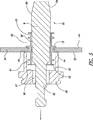
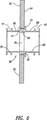
図3〜5は、第1の側面52、第2の側面54、およびこれら2つの側面52、54間を上記壁50を通って伸びる軸方向の開口部56を含む壁または圧力隔壁50を示す。図3では、58で指定される本発明の第1の継手の実施形態は、開口部56から軸方向に間隔を置いて示される。図6は、開口部56の内側に位置決めされ、そして壁50に固定される継手58を示す。図7は、図6と同様の図であるが、第1の導管60および第2の導管62の端部部分をさらに含む。第1の導管60は、上記壁50の第1の側面上にある。第2の導管62は、上記壁50の対向する側面または第2の側面上にある。
(Description of Detailed Embodiment)
3-5 show a wall or
好ましい形態では、継手58は、上記第1の端部部分66と第2の端部部分68との間で軸方向に位置決めされているリング部分64を備える。リング部分64は、第1の端部70および第2の端部72を含む。半径方向フランジ75は、上記リング部分64の第2の端部72に隣接する継手58から半径方向の外側方向に伸びる。リング部分64は、外径74および内径76を含む。端部部分66、68は、互いに実質的に等しくあり得るが、直径が上記リング部分64の内径76より大きい内径78、80を含む。
In a preferred form, the
図4および5に示されるように、上記継手58は、開口部58、第1の端部部分66中に最初挿入される。この第1の端部部分66は上記開口部56と整列され、そして次に、端部部分66は、上記開口部56に向かって、かつそれを通って移動される。最終的に、リング部分64の第1の端部70は、開口部56中にかつそれを通って移動される。
As shown in FIGS. 4 and 5, the joint 58 is initially inserted into the
リング部分64の外径74は、それが、開口部56内にぴったりと適合可能であるようなサイズである。継手58は、フランジ75が壁表面54に接触するまで、軸方向に移動される。壁表面54に対するフランジ75のこの位置は、図5および6に示されている。フランジ75が表面54に対している場合、リング部分64は、開口部56内にある。端部部分66は、表面52を含む側壁50上でリング部分64から軸方向の外側に突き出る。端部部分68は、表面54を含む壁50の側面上でリング部分64から軸方向の外側に突き出る。本明細書中以下に記載される様式で、スプリットスリーブおよびマンドレルまたはマンドレルのみが、開口部56内でリング部分64を拡張させるために継手58を通って軸方向に移動される。マンドレルのみが使用される場合、このマンドレルは、中実のマンドレルであってもよく、スプリットマンドレルであってもよい。スプリットスリーブが使用される場合、このスプリットスリーブは、リング部分の内側表面76に接触する。マンドレルのみが使用される場合(中実またはスプリット)、そのマンドレルの外側表面は、内側表面76に接触する。上記スプリットスリーブを通るマンドレルの軸方向の移動、またはマンドレル単独の軸方向の移動は、リング部分64の半径方向の拡張を引き起こし、その内径および外径を増加させて開口部56の壁と密接な締まりばめを形成する。この拡張は、開口部56内の壁にリング部分64を固定し、そして継手58を壁50に固定するに十分である。好ましくは、付与される拡張量は、上記材料の疲労増強のために、開口部56を取り囲む壁50中でその材料を冷間加工するに十分である。リング部分64の拡張は、その内径および外径の両方を増加させる。しかし、その内径は、拡張ツール(道具)が継手58の端部部分66、68の内側表面78,80を拡張させるような程度までは決して拡張されない。つまり、継手58のリング部分64およびそれが端部部分に取り付けられている場所だけが半径方向に拡張される。端部部分66、68は、コネクタ構成要素としてのそれらの機能を実行するようなサイズであり、そしてもとのサイズは、その機能に有害な量だけ、継手58を通る拡張ツールの移動によって変化されない。
The
1993年9月21日にMicheal A.Landy、Roger T.Bolstad、Charles A.Copple、Darryl E.Quincey、Eric T.Easterbrook、Leonard F. ReidおよびLouis A.Champouxに許可された米国特許第5,245,743号は、壁の開口部中に継手を取り付けるためのスプリットスリーブおよびマンドレルの使用を開示する。それは、中実のマンドレル(図22および23)およびスプリットマンドレル(第8欄、51〜55行)の両方の使用を開示する。スプリットマンドレルだけを使用するマンドレルだけのプロセスは、1987年5月19日にFranciscus Hogenhoutに許可され、そしてWest Coast Industries,Inc.に譲渡された米国特許第4,665,732号により開示されている。これらの特許の開示は、それらが開示するすべてについて、本明細書中に参考として援用される。 On September 21, 1993, Michael A. Landy, Roger T. Bolstad, Charles A. Couple, Darryl E. et al. Quinsey, Eric T. Esterbrook, Leonard F.E. Reid and Louis A. U.S. Pat. No. 5,245,743 granted to Champaux discloses the use of a split sleeve and mandrel to mount a fitting in a wall opening. It discloses the use of both solid mandrels (FIGS. 22 and 23) and split mandrels (column 8, lines 51-55). A mandrel-only process that uses only split mandrels was granted to Franciscus Hogenhout on May 19, 1987, and West Coast Industries, Inc. U.S. Pat. No. 4,665,732 assigned to U.S. Pat. The disclosures of these patents are hereby incorporated by reference for all that they disclose.
図4および5は、上記継手の内部のマンドレルMを示す。マンドレルMは、ベース端部82、テーパー状の先端片84、最大半径領域86、減少半径セクション88および遷移セクション90を含む。遷移セクション90では、その直径はセクション88における直径から最大直径領域86まで増加する。図4および5に示されるように、上記マンドレルのより小さい直径部分88は、継手58の中央開口部に適合し、かつそれを通るようなサイズである。セクション88では、リング部分64の内径76は、上記マンドレルの直径よりもわずかに大きい。
4 and 5 show the mandrel M inside the joint. The mandrel M includes a
マンドレルMは、図4および5に示される様式で、継手58の中へ移動される。次いで、マンドレルMのベース端部82は、引き抜き具ユニット内の可動部材に固定される。この引き抜き具ユニットは、工作物50と接触するように適合されている端部94を有する先端片92(図5)を含む。この引き抜き具は示されていないが、1993年6月15日にRichard Z.Jarzebowicz、Joy S.Ransom、Eric T.Easterbrook、Charles M.CoppleおよびLeonard F.Reidに許可された米国特許第5,218,854号に開示されている引き抜き具と類似であり得る。この特許に開示されるように、マンドレルMのベース端部82は、油圧式で前後方向に移動される軸方向に可動式のプッシュ−プル部材の外側端部部分と係合されるように適合されている。
The mandrel M is moved into the fitting 58 in the manner shown in FIGS. Next, the
図5を参照して、先端片92は、中央開口部98を有する背面端部96を含む。中央開口部98は、マンドレルMの最大直径セクション86を受容するようなサイズである。継手58を通してマンドレルMを引張るために、引き抜き具(示さず)は、マンドレルMのベース82上で引張るように作動される。最初は、マンドレルセクション88は、自由に継手58の内部を通過する。このことは、遷移セクション90がリング部分64の内径76に近づくまで起こる。セクション90がリング部分64を通るとき、それは、次第にリング部分64上で、半径方向の外側に向けられた力を付与する。この半径方向の力は、リング部分64の直径を増加させ、そしてその外側表面74を開口部56の内部表面に対して移動させる。リング部分64は、半径方向の外側に向かう力を、開口部56を丁度取り囲む壁50の材料に負荷する。リング部分64は、マンドレルMによって、表面74と開口部56の壁との間の密接した締りばめが存在するように、リング部分64を可塑的に拡張させるに十分な量、拡張させられる。拡張の程度は、好ましくは、開口部56を丁度取り囲む壁材料50を可塑的に拡張させるに十分大きい。第一の拡張は、締まりばめをもたらし、継手58を開口部56中に固定する。開口部56を取り囲む壁材料のさらなる拡張は、壁材料の疲労増強を提供する。マンドレルMが継手58を通して引かれているとき、遷移セクション90とリング部分64の内部表面76との接触により引き起こされる摩擦は、フランジ75を壁54に対して密接に引張るよう作用をする。移動しているマンドレルはまた、先端片92に作用力(reacting force)をもたらし、フランジ75に対向する側面52上で、壁50に対して端部表面94を移動させる。
With reference to FIG. 5, the
半径方向フランジ75は、必須の要素ではない。先端片96は、半径方向表面97を含む。もしフランジ75が省略されれば、この表面97は、それが継手58の端部表面99に接触する場所まで拡張され得る。この接触は、継手58が、継手58を通して引張られるマンドレルMに応答して、軸方向に移動することを防ぐ。
The
セクション90および86がリング部分64の内径76を通って移動されているときは、マンドレルセクション88は、開口部98を通って移動している。最大直径部分86が開口部76を通ってしまうまで、マンドレルMは、引張られる。これが起こる場合、引き抜き具/マンドレルアセンブリは、壁50から離れて引っぱられ得、図6により示されるように、継手58を壁に取付けたまま残す。継手58を通るマンドレルMの移動の間のどの時点でも、マンドレルMの遷移直径セクション90および最大直径セクション86は、継手58の端部部分66、68の内部表面78、80を実質的な量だけ拡張させない。マンドレルセクション90、86により実質的な量だけ接触されかつ拡張されるのはリング部分64だけである。端部部分66、68の内径および外径は、それらがリング部分64に結合する場所を除いて、サイズおよび形状において変化しない。従って、それらは、壁50の対向する側面で導管セクション60、62へ継手58を連結するというそれらの機能のために設計され得る。
When
図3〜8に示されるように、端部部分66、68は、リング部分64から軸方向の外側に間隔を置かれる半径方向の外側に開口する周囲溝またはチャネル91、93を含む。導管セクション60、62はまた、半径方向の外側に開口する周囲溝またはチャネル100、102を含む。チャネル91、93、100、102は、すべて図8に示されるように、Oリングシール104を受容するように構成されている。適切なクランプ構造106、108は、導管セクションの端部部分に継手の端部部分を連結するために提供される。代表的であるがしかし非限定的な例として、この連結部は、1981年2月10日にGeorge A. Mahoffに許可され、そしてHydro−Flow Supply,Inc.に譲渡された米国特許第4,249,786号に開示される連結部と同様であり得る。特に、この特許の図4を参照のこと。この連結部およびそのパーツは、同様に米国特許第4、249,786号に開示されているので、この開示は、本明細書中で詳細には繰り返さない。むしろ、米国特許第4、249,786号の内容は、本明細書中にこの特定の参照によって援用される。
As shown in FIGS. 3-8,
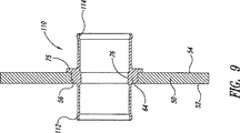
図9〜12は、壁継手の改変された構成を示す。継手110(図9)は、図3〜8により示される構成と非常に類似の構成を示す。しかし、半径方向の外側に向かう周囲溝は、導管セクションの端部で異なるタイプの構成要素(示さず)を受容して連結するように適合されている半径方向の内側に向けられた周囲溝112、114に置き換えられる。 9-12 show a modified configuration of the wall joint. Fitting 110 (FIG. 9) exhibits a configuration very similar to that shown by FIGS. However, the radially outward circumferential groove is a radially inwardly directed circumferential groove 112 that is adapted to receive and connect different types of components (not shown) at the end of the conduit section. , 114.
図10は、壁開口部56にあるリング部分118、および単独の端部部分120を含む継手116を示す。端部部分120は、半径方向フランジ122およびねじ山がある端部部分124を含む。このねじ山は、図1に示される端部部分16上のねじ山と同様であり得る。この実施形態では、他の実施形態におけるのと同様に、他の実施形態に関連して上に記載されたのと同じ理由で、リング部分118の内径は、このリング部分の外径よりも小さい。
FIG. 10 shows a
図11に示される継手126は、リング部分64から軸方向の外側に伸びる2つの端部部分128、130を有する。これらの端部部分128、130は、半径方向の外側に開口する周囲リング132、134の改変された構成を示す。
The joint 126 shown in FIG. 11 has two
図12は、リング部分64および2つの端部部分136、138を示す。この実施形態では、リング部分64は、以前に述べられた理由で、端部部分136、138よりも小さい内径を有する。この実施形態では、端部部分136、138は、それらを導管セクションに連結する際に使用するための外側のねじ山140、142を有する。フランジ75は、六角形の外側形状、すなわち、六角ナットのような形状を有し得る。このことにより、継手が端部のネジ山140、142にねじ込まれている場合に、それがレンチにより握られ得ることを可能にする。
FIG. 12 shows a
例示された実施形態は、本発明の例に過ぎず、それ故に、非限定的である。本発明の特定の構造、材料、および特徴において多くの変更が、本発明の趣旨および範囲から逸脱することなくなされ得ることが理解されるべきである。それ故に、本特許の権利が、本明細書中に例示され記載された特定の実施形態によって限定されず、むしろ、以下の特許請求の範囲によって限定され、均等論の使用およびパーツの転換を含む、受け入れられた特許請求項の解釈の原理に従って解釈されることが出願人の意図である。 The illustrated embodiments are merely examples of the present invention and are therefore non-limiting. It should be understood that many changes in the specific structure, material, and features of the invention may be made without departing from the spirit and scope of the invention. Therefore, the rights of this patent are not limited by the specific embodiments illustrated and described herein, but rather are limited by the following claims, including the use of equivalence and part conversion Applicant's intention is to be construed in accordance with the principles of accepted claim interpretation.
Claims (13)
外側周縁および内側周縁を有するリング部分であって、該外側周縁部分が、該工作物中の開口部よって緊密に受容可能である、リング部分;
少なくとも、最小の内側周縁、外側エンベロープ、および端部セクションを有する第1のカップリング部材であって、該カップリング部材は、該リング部分から軸方向に伸び、該最小の内側周縁が該リング部分の内側周縁より大きく、該外側エンベロープが該工作物中の開口部を通って移動するようなサイズであり、そして該端部セクションが別のデバイスと係合可能であるような形態である、第1のカップリング部材;を備え、
該リング部分が半径方向に拡張可能であり、拡張の量が該リング部分の外側周縁と該工作物中の開口部との間に強固な締まりばめを確立するに十分であり、該リング部分の外側周縁が、少なくとも該第1のカップリング部材の隣接する部分の外側周縁より大きく、該リング部分が該リング部分の外側周縁が該工作物中の開口部内にあるとき、該工作物に隣接して位置決めされる半径方向フランジを含む、管状の継手。A tubular joint that can be received by an opening in a workpiece:
A ring portion having an outer periphery and an inner periphery, the outer periphery portion being closely receivable by an opening in the workpiece;
A first coupling member having at least a minimum inner periphery, an outer envelope, and an end section, the coupling member extending axially from the ring portion, wherein the minimum inner periphery is the ring portion large Ri by the inner periphery of a size such as the outer envelope moves through the opening in the workpiece, and is configured end portion section is engagable with another device, A first coupling member;
The ring portion is a radially expandable, is sufficient to amount of extended to establish an interference fit firmly between the outer circumference and the opening of該工in crops of the ring portion, the ring portion The outer periphery of the first coupling member is at least greater than the outer periphery of the adjacent portion of the first coupling member, and the ring portion is adjacent to the workpiece when the outer periphery of the ring portion is within an opening in the workpiece. Tubular fitting including a radial flange positioned as a
外側周縁および内側周縁を有するリング部分であって、該外側周縁部分が該工作物中の開口部よって緊密に受容可能であり、該内側周縁部分が該導管のセクションを受容するようなサイズであり、該リング部分は、半径方向に拡張可能であり、ここで、拡張の量が、該リング部分の外側周縁と該工作物中の開口部との間の強固な締まりばめを確立するに十分である、リング部分;
少なくとも、最小の内側周縁、外側エンベロープ、および端部セクションを有する少なくとも1つのカップリング部材であって、該カップリング部材は、該リング部分から軸方向に伸び、該最小の内側周縁が該リング部分の内側周縁より大きく、該外側エンベロープが該工作物中の開口部を通って移動するようなサイズであり、そして該端部セクションが少なくとも1つの他のデバイスとカップルするような形態であり、該リング部分の外側周縁が、少なくとも該第1のカップリング部材の隣接する部分の外側周縁より大きい、カップリング部材;および
該リング部分の外側周縁から外方に延びる半径方向フランジであって、該リング部分が該工作物中の開口部によって緊密に受容されるとき、該工作物の一部分に対して接し、そして該工作物の一部に沿って半径方向の外方に延びるような寸法である、該半径方向フランジ、を備える、継手。A joint for firmly establishing a conduit path through an opening in a workpiece:
A ring portion having an outer periphery and an inner periphery, the outer periphery portion being closely receivable by an opening in the workpiece, the inner periphery portion being sized to receive a section of the conduit The ring portion is radially expandable, where the amount of expansion is sufficient to establish a strong interference fit between the outer periphery of the ring portion and the opening in the workpiece. A ring portion;
At least one coupling member having at least a minimum inner perimeter, an outer envelope, and an end section, the coupling member extending axially from the ring portion, wherein the minimum inner perimeter is the ring portion large Ri by the inner periphery of a size such as the outer envelope moves through the opening in the workpiece, and Ri forms der like end portion sections will couple at least one other device A coupling member , wherein an outer periphery of the ring portion is at least greater than an outer periphery of an adjacent portion of the first coupling member; and a radial flange extending outwardly from the outer periphery of the ring portion; When the ring portion is tightly received by an opening in the workpiece, it abuts against a portion of the workpiece and the workpiece A fitting comprising the radial flange dimensioned to extend radially outward along a portion of the object.
該工作物中の開口部中に緊密に受容されるようなサイズである外径を有する挿入物であって、該挿入物を通り、そしてそれ故、該工作物中の開口部を通る流体連通を提供する内側通路を有し;該工作物と締まりばめを形成するよう半径方向にかつ可塑的に拡張されるよう十分に可鍛性である、挿入物;および
第1の端部、第2の端部、および該挿入物との流体連通を提供する内側通路を有する少なくとも1つのカップリング部材であって、該挿入物から軸方向に伸び、該カップリング部材の第1の端部が該挿入物の近位方向に位置決めされ、該カップリング部材の第2の端部が少なくとも1つの導管とカップルされるよう作動可能である、カップリング部材、を備え、ここで、該挿入物が、該挿入物の外側周縁が該工作物の開口部内にあるとき、該工作物に隣接して位置決めされる半径方向フランジを含み、該挿入物の外側周縁が、該少なくとも1つのカップリング部材の隣接する部分の外側周縁より大きい、継手アセンブリ。A joint assembly for bridging an opening in a workpiece comprising:
An insert having an outer diameter that is sized to be closely received in an opening in the workpiece, wherein the fluid communication is through the insert and therefore through the opening in the workpiece. An insert that is sufficiently malleable to expand radially and plastically to form an interference fit with the workpiece; and a first end, At least one coupling member having an inner passage for providing fluid communication with the insert, wherein the first end of the coupling member extends axially from the insert. A coupling member positioned proximally of the insert and operable to couple a second end of the coupling member with at least one conduit, wherein the insert The outer periphery of the insert is within the opening of the workpiece Can, seen including a radial flange which is positioned adjacent to the workpiece, an outer peripheral edge of the insert is larger than the outer periphery of the adjacent portions of said at least one coupling member, the joint assembly.
継手の第1の部分を工作物中の開口部に挿入する工程であって、該継手の第1の部分が該開口部によって受容されるに十分なサイズの外側エンベロープを有し、該継手が該工作物の開口部中に位置決めされるリング部分をさらに有し、該リング部分が該第1の部分と連結され、ここで、該第1の部分が該リング部分から軸方向に伸び、該リング部分が該工作物の開口部内に密接に適合し、そしてカップリング部材であって該リング部分から半径方向に拡張するように構成されたカップリング部材の隣接する部分の外側周縁より大きいサイズの外側周縁を有し、該リング部分が、該リング部分の外側周縁が該工作物中の開口部内にあるとき、該工作物に隣接して位置決めされる半径方向フランジを含む、工程;
該工作物中に位置する継手を通じてマンドレルを挿入する工程であって、該継手のリング部分が該マンドレルの増加した周縁セクションによって半径方向に拡張可能である内側周縁を有し、該継手の第1の部分が該マンドレルの増加した周縁セクションよりわずかにより大きいサイズの内側周縁を有する、工程;および
該継手のリング部分を、該マンドレルが該リング部分の内側周縁を通って押されるとき半径方向外側に拡張する工程、を包含する、方法。A method for routing a conduit through an opening in a workpiece, comprising:
Inserting a first portion of a joint into an opening in a workpiece, the first portion of the joint having an outer envelope of a size sufficient to be received by the opening; A ring portion positioned in the opening of the workpiece, the ring portion being coupled to the first portion, wherein the first portion extends axially from the ring portion, and A ring portion that fits closely within the opening of the workpiece and is a coupling member that is larger in size than the outer periphery of an adjacent portion of the coupling member configured to radially expand from the ring portion . Having an outer periphery and the ring portion includes a radial flange positioned adjacent to the workpiece when the outer periphery of the ring portion is within an opening in the workpiece;
Inserting a mandrel through a joint located in the workpiece, wherein the ring portion of the joint has an inner periphery that is radially expandable by an increased peripheral section of the mandrel; A portion of the joint having an inner periphery that is slightly larger in size than the increased peripheral section of the mandrel; and the ring portion of the joint radially outward when the mandrel is pushed through the inner periphery of the ring portion Expanding the method.
Applications Claiming Priority (3)
| Application Number | Priority Date | Filing Date | Title |
|---|---|---|---|
| US10/633,294 | 2003-07-31 | ||
| US10/633,294 US7448652B2 (en) | 2003-07-31 | 2003-07-31 | Tubular metal fitting expandable in a wall opening and method of installation |
| PCT/US2004/024119 WO2005011886A2 (en) | 2003-07-31 | 2004-07-27 | Tubular metal fitting expandable in a wall opening and method of installation |
Publications (3)
| Publication Number | Publication Date |
|---|---|
| JP2007500828A JP2007500828A (en) | 2007-01-18 |
| JP2007500828A5 JP2007500828A5 (en) | 2007-09-13 |
| JP4819678B2 true JP4819678B2 (en) | 2011-11-24 |
Family
ID=34104562
Family Applications (1)
| Application Number | Title | Priority Date | Filing Date |
|---|---|---|---|
| JP2006521989A Active JP4819678B2 (en) | 2003-07-31 | 2004-07-27 | Tubular metal fittings expandable in wall openings and methods of installation |
Country Status (7)
| Country | Link |
|---|---|
| US (2) | US7448652B2 (en) |
| EP (1) | EP1651365B1 (en) |
| JP (1) | JP4819678B2 (en) |
| KR (1) | KR20060057590A (en) |
| CN (1) | CN100447469C (en) |
| BR (1) | BRPI0413120A (en) |
| WO (1) | WO2005011886A2 (en) |
Families Citing this family (24)
| Publication number | Priority date | Publication date | Assignee | Title |
|---|---|---|---|---|
| US7375277B1 (en) | 2000-06-26 | 2008-05-20 | Fatigue Technology, Inc. | Double flanged bushings and installation methods |
| US7448652B2 (en) * | 2003-07-31 | 2008-11-11 | Fatigue Technology Inc. | Tubular metal fitting expandable in a wall opening and method of installation |
| US20060038074A1 (en) * | 2004-05-07 | 2006-02-23 | Buhr Theo D | Connecting element for connecting a conduit system to cooling aggregates in aircraft cabins |
| US20070110541A1 (en) * | 2005-10-28 | 2007-05-17 | Fatigue Technology, Inc. | Radially displaceable bushing for retaining a member relative to a structural workpiece |
| EP3199292B1 (en) | 2005-12-28 | 2020-03-11 | Fatigue Technology, Inc. | Mandrel assembly and method of using the same |
| CA2637100A1 (en) * | 2006-01-11 | 2007-07-19 | Fatigue Technology, Inc. | Bushing kits, bearings, and methods of installation |
| JP5258751B2 (en) | 2006-04-27 | 2013-08-07 | ファティーグ テクノロジー インコーポレイテッド | Alignment device and method of using the same |
| JP5204096B2 (en) | 2006-04-27 | 2013-06-05 | ファティーグ テクノロジー インコーポレイテッド | Wave relaxation geometry in a structural member that is radially expandable into the workpiece |
| US20080005887A1 (en) * | 2006-05-26 | 2008-01-10 | Fatigue Technology, Inc. | Elongated member/radially expandable member assembly and methods of assembling the same |
| US7958766B2 (en) * | 2006-06-29 | 2011-06-14 | Fatigue Technology, Inc. | Self-aligning tools and a mandrel with retention sleeve |
| EP2489462A1 (en) * | 2006-08-28 | 2012-08-22 | Fatigue Technology, Inc. | System for processing a workpiece and method of expanding an expandable member |
| EP2158409A2 (en) * | 2007-05-15 | 2010-03-03 | Fatigue Technology, Inc. | Blind installed expandable collar and threaded inner member |
| EP2210001B1 (en) | 2007-10-16 | 2017-08-02 | Fatigue Technology, Inc. | Expandable fastener assembly with deformed collar |
| JP5606332B2 (en) | 2008-03-07 | 2014-10-15 | ファティーグ テクノロジー インコーポレイテッド | Expandable member with wave suppression and method of use |
| EP2318726B1 (en) | 2008-07-18 | 2015-09-02 | Fatigue Technology, Inc. | Nut plate assembly and methods of using the same |
| EP2417369B1 (en) | 2009-04-10 | 2014-04-02 | Fatigue Technology, Inc. | Installable assembly having an expandable outer member and a fastener with a mandrel |
| WO2011084624A2 (en) | 2009-12-16 | 2011-07-14 | Fatigue Technology, Inc. | Modular nut plate assemblies and methods of using the same |
| WO2012167136A2 (en) | 2011-06-03 | 2012-12-06 | Fatigue Technology, Inc. | Expandable crack inhibitors and methods of using the same |
| US9114449B2 (en) | 2011-06-15 | 2015-08-25 | Fatigue Technology, Inc. | Modular nut plates with closed nut assemblies |
| US10130985B2 (en) | 2012-01-30 | 2018-11-20 | Fatigue Technology, Inc. | Smart installation/processing systems, components, and methods of operating the same |
| US11541581B2 (en) | 2016-09-02 | 2023-01-03 | Zurn Industries, Llc | Injection molded cold-expansion compression collar |
| US11543065B2 (en) | 2016-09-02 | 2023-01-03 | Zurn Industries, Llc | Extruded cold-expansion compression collar |
| US11054076B2 (en) | 2016-11-04 | 2021-07-06 | Zurn Industries, Llc | Reinforcing ring with sleeve |
| JP7243104B2 (en) * | 2018-09-27 | 2023-03-22 | 株式会社ノーリツ | Heat exchanger and manufacturing method thereof |
Citations (4)
| Publication number | Priority date | Publication date | Assignee | Title |
|---|---|---|---|---|
| JPS5088619A (en) * | 1973-12-10 | 1975-07-16 | ||
| US4249786A (en) * | 1978-11-03 | 1981-02-10 | Hydraflow Supply, Inc. | Flexible coupling |
| JPH10274366A (en) * | 1997-03-28 | 1998-10-13 | Niyuumach:Kk | Piping device for air conditioning equipment |
| JP2001177964A (en) * | 1999-12-14 | 2001-06-29 | Toban Shoji Kk | Device for joining buried pipe to connection, and junction structure using this |
Family Cites Families (164)
| Publication number | Priority date | Publication date | Assignee | Title |
|---|---|---|---|---|
| US295593A (en) | 1884-03-25 | Jambs f | ||
| GB593607A (en) | 1945-06-08 | 1947-10-21 | Arthur Buescher | Improvements in arbors |
| US810430A (en) | 1904-02-11 | 1906-01-23 | Frank Pfluger | Bung-hole bushing. |
| US1081496A (en) * | 1908-03-23 | 1913-12-16 | Horatio G Gillmor | Expander for pipes, tubes, &c. |
| US1106964A (en) | 1913-07-07 | 1914-08-11 | Martin A Pahler | Signal-cord bushing. |
| US1226090A (en) | 1917-03-31 | 1917-05-15 | Nat Bush Company | Bushing for bungs. |
| US1297142A (en) | 1918-07-19 | 1919-03-11 | William J Gibbons | Bushing-blank and process of making bushings. |
| US1480298A (en) | 1922-10-14 | 1924-01-08 | George A Pearson | Bezel |
| GB348631A (en) | 1929-11-13 | 1931-05-13 | Hall & Kay Ltd | Improvements in or relating to metal sockets, bushes, ferrules, rivets and the like |
| US1881867A (en) * | 1930-09-22 | 1932-10-11 | Vilter Mfg Co | Method of attaching annular elements to supporting structures |
| US2092358A (en) * | 1935-02-18 | 1937-09-07 | Robertson John Hogg | Tubular joint |
| US2150361A (en) * | 1935-05-20 | 1939-03-14 | Chobert Jacques Franco Gabriel | Method of and apparatus for securing hollow bodies in holes in other bodies |
| US2146461A (en) | 1937-01-06 | 1939-02-07 | Aviat Developments Ltd | Method of riveting |
| US2188596A (en) | 1939-05-05 | 1940-01-30 | Universal Clay Products Co | Removable bushing |
| US2275451A (en) | 1939-05-20 | 1942-03-10 | Babcock & Wilcox Co | Method of producing pressure tight tube and tube-seat connections |
| US2357123A (en) | 1939-05-20 | 1944-08-29 | Babcock & Wilcox Co | Apparatus for producing pressure-tight tube and tube seat connections |
| US2405399A (en) | 1943-09-22 | 1946-08-06 | Bugg | Tube beading and expanding tool and method |
| US2468985A (en) | 1943-11-26 | 1949-05-03 | Goodrich Co B F | Resilient connection and method of making same |
| US2385294A (en) | 1944-06-17 | 1945-09-18 | New York Engineering Company | Bung bushing |
| US2430554A (en) | 1944-06-21 | 1947-11-11 | Bugg | Tool for beading and flaring tubes |
| US2433425A (en) * | 1945-03-20 | 1947-12-30 | Aero Coupling Corp | Fabricated high-pressure coupling |
| US2528180A (en) * | 1946-03-02 | 1950-10-31 | William J Roehl | Pipe clamp |
| US2661182A (en) | 1948-02-02 | 1953-12-01 | Samuel M Kipp | Multiway piston valve with removable bushing and packing structure |
| US2695446A (en) * | 1950-06-30 | 1954-11-30 | Metallschlauchfabrik Ag | Method of making tube-to-flange connection |
| US2700172A (en) | 1952-01-28 | 1955-01-25 | Frederick W Rohe | Sectional grommet for reinforcing openings in panels and sheets |
| US2672175A (en) | 1952-06-03 | 1954-03-16 | Russell B Howard | Pipe expander |
| US2808643A (en) * | 1954-07-13 | 1957-10-08 | Weatherhead Co | Method of fabricating hose coupling members |
| US2943667A (en) | 1957-10-14 | 1960-07-05 | Arrowsmith Tool & Die Corp | Expanding mandrel hydro-press |
| US3164054A (en) | 1962-04-13 | 1965-01-05 | Illinois Tool Works | Bushing with rib and shoulder means |
| US3149860A (en) * | 1961-01-16 | 1964-09-22 | Boeing Co | High pressure, high temperature reconnectible tube fitting |
| US3137887A (en) | 1962-06-15 | 1964-06-23 | Republic Aviat Corp | Bushing |
| US3128999A (en) | 1962-09-17 | 1964-04-14 | Lord Mfg Co | Resilient mounting |
| US3345730A (en) | 1963-10-16 | 1967-10-10 | Murray Mfg Corp | Apparatus for affixing a flange to a tube |
| US3244034A (en) | 1963-11-19 | 1966-04-05 | Anton M Severdia | Locking and retaining slip removable bushings |
| US3252493A (en) | 1964-05-22 | 1966-05-24 | Gen Dynamics Corp | Three part fastener with spacer means |
| US3358492A (en) | 1965-09-08 | 1967-12-19 | Embassy Ind Inc | Mandrel construction |
| US3434746A (en) * | 1966-08-10 | 1969-03-25 | Amp Inc | Flexible tube coupling |
| US3537163A (en) | 1968-04-30 | 1970-11-03 | Robert H Steidl | Method of installing a cylindrical element into a cylindrical bore |
| US3498648A (en) * | 1968-08-22 | 1970-03-03 | Boeing Co | High temperature and pressure tube fitting |
| US3693247A (en) | 1968-10-03 | 1972-09-26 | Clarence K Brown | Method of securing together a plurality of structural members |
| US3566662A (en) | 1969-04-28 | 1971-03-02 | Boeing Co | Coldworking method and apparatus |
| US3674292A (en) * | 1969-10-15 | 1972-07-04 | Amp Inc | Tubular connection devices |
| US3835525A (en) | 1970-04-30 | 1974-09-17 | J King | Method of fabricating a joint |
| GB1395009A (en) | 1971-05-26 | 1975-05-21 | Warner Son Engs Ltd Ray | Device for use in collapsible tube manufacture |
| DE2203217A1 (en) | 1972-01-24 | 1973-07-26 | Honsel Nieten & Metallwarenfab | SETTING TOOL FOR BLIND RIVET NUTS |
| US3778090A (en) * | 1972-05-18 | 1973-12-11 | Gen Motors Corp | Beaded tube with o-ring seal connection |
| US3820297A (en) | 1972-11-10 | 1974-06-28 | Huck Mfg Co | Interference fit blind fastener |
| US4164807A (en) | 1974-03-19 | 1979-08-21 | King John O Jun | Method of forming a coldworked joint |
| US3875649A (en) | 1973-01-17 | 1975-04-08 | King John O Jun | Coldworking method and apparatus with frangible head flange |
| US3949535A (en) | 1973-01-17 | 1976-04-13 | King John O Jun | Coldworked joint held by seamless tubular member |
| US3787945A (en) * | 1973-05-14 | 1974-01-29 | Gen Motors Corp | Method of fabricating an expanded tube connection |
| GB1469406A (en) | 1973-05-29 | 1977-04-06 | Automatic Fastener Corp | Fastener setting apparatus |
| US3895409A (en) | 1973-08-31 | 1975-07-22 | Johns Manville | Spacer grommet and method of manufacture thereof |
| US3892121A (en) | 1973-09-12 | 1975-07-01 | Boeing Co | Apparatus for cold-working holes |
| DK638174A (en) * | 1973-12-10 | 1975-08-11 | Kubota Ltd | |
| US3915052A (en) | 1974-08-22 | 1975-10-28 | Huck Mfg Co | Self broaching fastener assembly and like self sizing fasteners |
| US4143580A (en) | 1976-12-20 | 1979-03-13 | Allfast, Inc. | Lock spindle blind rivet |
| SU632463A1 (en) | 1977-04-05 | 1978-11-15 | Предприятие П/Я А-1264 | Apparatus for riveting wedge-shaped stacks |
| US4187708A (en) | 1977-04-11 | 1980-02-12 | Industrial Wire & Metal Forming, Inc. | Pulling apparatus and method |
| JPS6024169Y2 (en) | 1980-02-29 | 1985-07-19 | ワイケイケイ株式会社 | eyelet |
| EP0054592A1 (en) | 1980-12-23 | 1982-06-30 | Incom International Inc. | Method of manufacturing spherical bearings |
| US4355612A (en) | 1981-02-06 | 1982-10-26 | Outboard Marine Corporation | Cooling system with removable valve member |
| US4405256A (en) | 1981-04-14 | 1983-09-20 | King John O Jun | Cushioned fastener joint |
| SE450660B (en) | 1981-04-21 | 1987-07-13 | Reheat Ab | PROCEDURE FOR LINING THE FLUIDUM CONNECTION OPENING IN A STATUS PLATE FOR PLATE HEAT EXCHANGER |
| US4423619A (en) | 1981-06-15 | 1984-01-03 | Fatigue Technology, Inc. | Apparatus and method for prestressing a countersunk fastener hole |
| CA1199353A (en) * | 1981-09-21 | 1986-01-14 | Boart International Limited | Connection of drill tubes |
| US4386515A (en) | 1981-12-30 | 1983-06-07 | Usm Corporation | Setting tool for blind fasteners |
| US4524600A (en) | 1982-02-10 | 1985-06-25 | Champoux Robert L | Apparatus for prestressing fastener holes |
| US4425780A (en) | 1982-02-10 | 1984-01-17 | Fatigue Technology, Inc. | Apparatus having extended prestressing and sleeve retaining devices for prestressing countersunk fastener holes and method |
| US4471643A (en) | 1982-02-10 | 1984-09-18 | Fatigue Technology, Inc. | Method and apparatus for prestressing fastener holes |
| US4447944A (en) | 1982-06-16 | 1984-05-15 | The United States Of America As Represented By The Secretary Of The Navy | Method of forming a tubular rivet in fastening relation to a plurality of laminates |
| SE456856B (en) | 1982-06-18 | 1988-11-07 | Alfa Laval Thermal Ab | PLATE HEAT EXCHANGE AND WERE TO INFO A CONNECTION PORT IN THIS |
| WO1984000120A1 (en) | 1982-07-01 | 1984-01-19 | Rast Patent Mfg Pty | Tube expander |
| US4597282A (en) | 1983-01-14 | 1986-07-01 | West Coast Industries, Inc. | Method and apparatus for coldworking holes |
| DE3301849C1 (en) | 1983-01-20 | 1984-07-12 | MTG Montagetechnik Peter Ernst GmbH, 5758 Fröndenberg | Clamping blind rivet |
| US4640479A (en) | 1983-01-31 | 1987-02-03 | All States Inc. | Strain relief grommet |
| US4557033A (en) | 1983-07-11 | 1985-12-10 | Fatigue Technology, Inc. | Method of cold expanding and sizing fastener holes |
| GB8322719D0 (en) * | 1983-08-24 | 1983-09-28 | Adaptaflex Ltd | End fittings for flexible conduits |
| US4665732A (en) * | 1983-09-30 | 1987-05-19 | West Coast Industries, Inc. | Method and apparatus for hole coldworking |
| US4583388A (en) | 1983-09-30 | 1986-04-22 | West Coast Industries, Inc. | Method and apparatus for hole coldworking |
| US4522378A (en) | 1983-11-02 | 1985-06-11 | Illinois Tool Works, Inc. | Wiper motor mounting grommet |
| JPS60238046A (en) | 1984-05-10 | 1985-11-26 | Nippon Alum Mfg Co Ltd:The | Pipe expander |
| DE3545554A1 (en) | 1985-12-21 | 1987-07-02 | Sueddeutsche Kuehler Behr | Tube base connection for heat exchanger - uses sleeve with collar in tube ends |
| US4755904A (en) | 1986-06-06 | 1988-07-05 | The Boeing Company | Lightning protection system for conductive composite material structure |
| US4759237A (en) | 1986-12-18 | 1988-07-26 | Fauchet Christian R | Self-locking nut and tightening tool |
| US4787793A (en) | 1987-03-27 | 1988-11-29 | Terrell Lee Sharp | Bolt guard |
| US4905766A (en) * | 1987-04-28 | 1990-03-06 | R&G Sloane Mfg. Co., Inc. | Adapter for plastic pipe |
| US4809420A (en) | 1987-12-16 | 1989-03-07 | Fatigue Technology, Inc. | Method and apparatus for backing up mandrel exit holes in knuckle structures |
| IT1215911B (en) | 1988-02-18 | 1990-02-22 | Cembre Srl | PERMANENT ELECTRIC CONTACT APPLICABLE TO THE SOUL OF SIMILAR RAILS. |
| US4869091A (en) | 1988-03-22 | 1989-09-26 | The Boeing Company | Tool for coldworking holes |
| US4985979A (en) | 1989-01-23 | 1991-01-22 | Mcdonnell Douglas Corporation | Method of installing interference fit sleeved fasteners having radiused intersection for stress coining |
| US4934170A (en) | 1989-02-16 | 1990-06-19 | Fatigue Technology, Incorporated | Fatigue life enhancement of noncircular openings |
| US4885829A (en) | 1989-02-16 | 1989-12-12 | Fatigue Technology, Incorporated | Fatigue life enhancement of dovetail connector slots and noncircular openings |
| FR2645052B1 (en) | 1989-03-31 | 1996-07-26 | Virax Sa | IMPROVEMENTS ON EXPANSION TOOLS MOUNTED ON AN APPARATUS FOR SHAPING THE END OF TUBES |
| US5088194A (en) * | 1989-04-10 | 1992-02-18 | Lasko John A | Fluid distribution system, and apparatus and method for making same |
| US4934038A (en) | 1989-09-15 | 1990-06-19 | Caterpillar Inc. | Method and apparatus for tube expansion |
| US4999896A (en) | 1989-10-25 | 1991-03-19 | Gemcor Engineering Corporation | Automatic double-flush riveting |
| US5038596A (en) | 1989-12-01 | 1991-08-13 | Grumman Aerospace Corporation | Threaded cold working mandrel |
| GB2239917B (en) * | 1990-01-15 | 1993-09-29 | Fischer George Castings Ltd | An adaptor fitting |
| US5129253A (en) | 1990-01-26 | 1992-07-14 | Bell Helicopter Textron Inc. | Antifretting coating for a bushing in a coldworked joint |
| US5110163A (en) * | 1990-03-22 | 1992-05-05 | Lokring Corporation | Pipe fitting with improved coupling body |
| US5083363A (en) | 1990-07-25 | 1992-01-28 | Fatigue Technology, Inc. | Method of installing a grommet in a wall of composite material |
| US5096349A (en) * | 1990-07-26 | 1992-03-17 | Fatigue Technology, Inc. | Nut mounting grommet |
| US5405228A (en) | 1990-07-26 | 1995-04-11 | Fatigue Technology, Inc. | Nut cage and mount |
| US5245743A (en) * | 1990-07-26 | 1993-09-21 | Fatigue Technology, Inc. | Method of installing a nut mounting grommet |
| US5069586A (en) | 1990-08-27 | 1991-12-03 | Casey Marion B | Self-locking two-part grommet |
| CN2100541U (en) * | 1991-01-14 | 1992-04-01 | 黄金平 | Expansion tube joint |
| US5103548A (en) | 1991-05-13 | 1992-04-14 | Fatigue Technology, Inc. | Method and apparatus for securing a tubular bushing in a circular opening |
| US5093957A (en) | 1991-07-08 | 1992-03-10 | Atr International, Inc. | Compression fitting for use in a two-sided honeycomb panel |
| US5127254A (en) | 1991-07-10 | 1992-07-07 | Fatigue Technology, Inc. | Method and apparatus for split sleeve cold expansion of openings in structural members |
| US5305627A (en) | 1992-07-27 | 1994-04-26 | Fatigue Technology, Inc. | Split sleeve cold expansion |
| US5218854A (en) * | 1992-05-08 | 1993-06-15 | Fatigue Technology, Inc. | System for cold expanding holes in rail sections |
| US5253773A (en) * | 1992-08-26 | 1993-10-19 | General Signal Corporation | Filler tube for liquid containers |
| DE4301124C2 (en) | 1993-01-18 | 1996-10-17 | Danfoss As | Method of connecting a cylinder liner to a base body |
| US5341559A (en) | 1993-04-13 | 1994-08-30 | Fatigue Technology, Inc. | Method and apparatus for securing a tubular bushing in a circular opening |
| IL106286A (en) | 1993-07-07 | 1996-05-14 | Israel State | Surface connector |
| US5380136A (en) | 1993-09-14 | 1995-01-10 | Fatigue Technology, Inc. | Anchor nut mount |
| US5433100A (en) | 1993-11-12 | 1995-07-18 | Fatigue Technology, Inc. | Apparatus for split sleeve and tubular bushing cold expansion |
| US5380111A (en) | 1993-12-20 | 1995-01-10 | Westrom; S. John | Releasable spacer assembly for binders |
| BR9401280A (en) * | 1994-03-24 | 1994-10-11 | Helio Lanfranchi Seabra | Improvement applied in the process of locking the rotating connection. |
| US5466016A (en) * | 1994-04-11 | 1995-11-14 | General Motors Corporation | Solderless filler neck joint |
| JP3186492B2 (en) | 1995-02-17 | 2001-07-11 | 田中貴金属工業株式会社 | Bushing base plate and manufacturing method thereof |
| EP0759616B1 (en) | 1995-03-10 | 2001-05-23 | Nippon Petrochemicals Co., Ltd. | Metal-resin composite plate, rocking actuator with composite plate, and method for production thereof |
| US5607194A (en) * | 1995-04-20 | 1997-03-04 | Universal Enterprises, Inc. | Member and tube assembly |
| US5806173A (en) | 1995-07-28 | 1998-09-15 | Hidaka Seiki Kabushiki Kaisha | Tube expander |
| JPH0979033A (en) * | 1995-09-13 | 1997-03-25 | Sango Co Ltd | Joint structure of pipe member and plate body, jointing method, and muffler with this joint structure |
| USRE38788E1 (en) | 1997-07-04 | 2005-09-06 | Sumitomo Wiring Systems, Ltd. | Grommet |
| JP3175647B2 (en) | 1997-07-04 | 2001-06-11 | 住友電装株式会社 | Grommet |
| DE29712206U1 (en) | 1997-07-11 | 1997-08-28 | Kabelkonfektionstechnik Kkt Gm | Device for connecting an electrical line to a railroad track or the like. |
| US5947326A (en) | 1997-11-12 | 1999-09-07 | Alasco Rubber & Plastics Corporation | Bung and stopper |
| US5943898A (en) | 1998-02-17 | 1999-08-31 | Kuo; Albert S. | Method and apparatus to coldwork holes |
| ES2256901T3 (en) | 1998-03-22 | 2006-07-16 | Cembre Gmbh | PROCEDURE FOR ESTABLISHING A PERMANENT ELECTRICAL CONTACT IN THE SOUL OF A RAIL RAIL AND PERMANENT ELECTRICAL CONTACT OBTAINED WITH SUCH PROCEDURE. |
| US6131964A (en) * | 1998-12-15 | 2000-10-17 | Westinghouse Air Brake Company | SAS fitting for tube and pipe connections |
| JP3490927B2 (en) | 1999-05-19 | 2004-01-26 | ニチアス株式会社 | How to attach a vibrating floating washer to the heat shield |
| DE19935246B4 (en) * | 1999-06-04 | 2004-07-22 | Friatec Ag | Connectors |
| US6217082B1 (en) * | 1999-09-09 | 2001-04-17 | Dana Corporation | Swivel fitting |
| GB2358053B (en) | 1999-12-14 | 2003-11-19 | Textron Fastening Syst Ltd | Insert and method of installation thereof |
| US6347663B1 (en) * | 2000-03-13 | 2002-02-19 | Modine Manufacturing Company | Fitting/manifold assembly and method for a heat exchanger |
| US6266991B1 (en) | 2000-04-03 | 2001-07-31 | Albert S. Kuo | Coldwork holes with reusable seamless SMA sleeve |
| US6488460B1 (en) | 2000-05-02 | 2002-12-03 | Bell Helicopter Textron Inc. | Composite panel insert with hold out recess feature |
| US7375277B1 (en) | 2000-06-26 | 2008-05-20 | Fatigue Technology, Inc. | Double flanged bushings and installation methods |
| US8155256B2 (en) | 2000-10-23 | 2012-04-10 | Texas Instruments Incorporated | Method and apparatus for asynchronous clock retiming |
| US6623048B2 (en) * | 2001-05-17 | 2003-09-23 | Delphi Technologies, Inc. | Apparatus and method of attaching a tube member to a housing of a vacuum brake booster |
| US6499926B2 (en) | 2001-05-18 | 2002-12-31 | The Boeing Company | Fastener apparatus and method of fastening non-metallic structures |
| US6705149B2 (en) | 2001-05-25 | 2004-03-16 | Huck Patents, Inc. | Universal backup mandrel with retractable sleeve and shock absorbing means |
| US7059816B2 (en) | 2001-11-09 | 2006-06-13 | Textron Inc. | Nut plate |
| US6796765B2 (en) | 2001-12-27 | 2004-09-28 | General Electric Company | Methods and apparatus for assembling gas turbine engine struts |
| US6761380B2 (en) * | 2002-05-07 | 2004-07-13 | Delphi Technologies, Inc. | Filler neck assembly for fuel tank |
| US6651301B1 (en) | 2002-06-28 | 2003-11-25 | Yang-Ting Liu | Adjustable hand tool with dual functions |
| US7024908B2 (en) | 2003-07-10 | 2006-04-11 | Fatigue Technology, Inc. | Fatigue enhancement of material surrounding openings in workpieces |
| US7448652B2 (en) * | 2003-07-31 | 2008-11-11 | Fatigue Technology Inc. | Tubular metal fitting expandable in a wall opening and method of installation |
| US7024909B2 (en) | 2003-10-21 | 2006-04-11 | Alcoa Global Fasteners, Inc. | Non-impact swaging apparatus |
| US7047596B2 (en) | 2003-12-09 | 2006-05-23 | Sikorsky Aircraft Corp. | Structural bushing application for highly loaded composites lugs |
| US7406777B2 (en) | 2004-04-15 | 2008-08-05 | Fatigue Technology, Inc. | Method and apparatus employing eccentric bushing |
| US7464577B2 (en) | 2004-07-01 | 2008-12-16 | General Electric Company | Method for fabricating rotary machines |
| US20070110541A1 (en) | 2005-10-28 | 2007-05-17 | Fatigue Technology, Inc. | Radially displaceable bushing for retaining a member relative to a structural workpiece |
| CA2637100A1 (en) | 2006-01-11 | 2007-07-19 | Fatigue Technology, Inc. | Bushing kits, bearings, and methods of installation |
| DE102006019405B4 (en) | 2006-04-24 | 2011-08-18 | EADS Deutschland GmbH, 85521 | Tool for cold expansion of holes |
| JP5258751B2 (en) | 2006-04-27 | 2013-08-07 | ファティーグ テクノロジー インコーポレイテッド | Alignment device and method of using the same |
| JP5204096B2 (en) | 2006-04-27 | 2013-06-05 | ファティーグ テクノロジー インコーポレイテッド | Wave relaxation geometry in a structural member that is radially expandable into the workpiece |
| US20080005887A1 (en) | 2006-05-26 | 2008-01-10 | Fatigue Technology, Inc. | Elongated member/radially expandable member assembly and methods of assembling the same |
| US7958766B2 (en) | 2006-06-29 | 2011-06-14 | Fatigue Technology, Inc. | Self-aligning tools and a mandrel with retention sleeve |
| EP2489462A1 (en) | 2006-08-28 | 2012-08-22 | Fatigue Technology, Inc. | System for processing a workpiece and method of expanding an expandable member |
| US7695226B2 (en) | 2006-09-21 | 2010-04-13 | Alcoa Global Fasteners, Inc. | High performance sleeved interference fasteners for composite applications |
-
2003
- 2003-07-31 US US10/633,294 patent/US7448652B2/en not_active Expired - Lifetime
-
2004
- 2004-07-27 WO PCT/US2004/024119 patent/WO2005011886A2/en active Application Filing
- 2004-07-27 BR BRPI0413120-7A patent/BRPI0413120A/en not_active Application Discontinuation
- 2004-07-27 CN CNB2004800256031A patent/CN100447469C/en active Active
- 2004-07-27 EP EP04779253.6A patent/EP1651365B1/en active Active
- 2004-07-27 JP JP2006521989A patent/JP4819678B2/en active Active
- 2004-07-27 KR KR1020067002150A patent/KR20060057590A/en not_active Application Discontinuation
-
2008
- 2008-10-28 US US12/259,927 patent/US7946628B2/en not_active Expired - Lifetime
Patent Citations (4)
| Publication number | Priority date | Publication date | Assignee | Title |
|---|---|---|---|---|
| JPS5088619A (en) * | 1973-12-10 | 1975-07-16 | ||
| US4249786A (en) * | 1978-11-03 | 1981-02-10 | Hydraflow Supply, Inc. | Flexible coupling |
| JPH10274366A (en) * | 1997-03-28 | 1998-10-13 | Niyuumach:Kk | Piping device for air conditioning equipment |
| JP2001177964A (en) * | 1999-12-14 | 2001-06-29 | Toban Shoji Kk | Device for joining buried pipe to connection, and junction structure using this |
Also Published As
| Publication number | Publication date |
|---|---|
| CN100447469C (en) | 2008-12-31 |
| EP1651365A4 (en) | 2010-03-03 |
| US20050025601A1 (en) | 2005-02-03 |
| US7448652B2 (en) | 2008-11-11 |
| WO2005011886A2 (en) | 2005-02-10 |
| US20090224535A1 (en) | 2009-09-10 |
| EP1651365A2 (en) | 2006-05-03 |
| KR20060057590A (en) | 2006-05-26 |
| US7946628B2 (en) | 2011-05-24 |
| EP1651365B1 (en) | 2013-06-26 |
| WO2005011886A3 (en) | 2006-02-16 |
| JP2007500828A (en) | 2007-01-18 |
| BRPI0413120A (en) | 2006-10-03 |
| CN1846092A (en) | 2006-10-11 |
Similar Documents
| Publication | Publication Date | Title |
|---|---|---|
| JP4819678B2 (en) | Tubular metal fittings expandable in wall openings and methods of installation | |
| US6415488B1 (en) | Tube joint and apparatus for producing the same | |
| US7375277B1 (en) | Double flanged bushings and installation methods | |
| US6345431B1 (en) | Joining thermoplastic pipe to a coupling | |
| US4423619A (en) | Apparatus and method for prestressing a countersunk fastener hole | |
| AU2016244061B2 (en) | Swage fitting | |
| JPH01153891A (en) | Pipe joint | |
| US6827375B2 (en) | End fitting tubular members and method of applying same | |
| US11085566B2 (en) | Pressure sleeve | |
| US5896893A (en) | Pipe having ridge on spigot and method of forming the ridge | |
| US11193614B2 (en) | Pressure sleeve | |
| JP2758019B2 (en) | Pipe fittings | |
| KR920004644Y1 (en) | Steel pipe connector | |
| JP2596604Y2 (en) | Fluid pressure fittings | |
| JPH11182752A (en) | Pipe threading auxiliary tool | |
| JPH09280439A (en) | Pipe coupling |
Legal Events
| Date | Code | Title | Description |
|---|---|---|---|
| A521 | Request for written amendment filed |
Free format text: JAPANESE INTERMEDIATE CODE: A523 Effective date: 20070725 |
|
| A621 | Written request for application examination |
Free format text: JAPANESE INTERMEDIATE CODE: A621 Effective date: 20070725 |
|
| A977 | Report on retrieval |
Free format text: JAPANESE INTERMEDIATE CODE: A971007 Effective date: 20100615 |
|
| A131 | Notification of reasons for refusal |
Free format text: JAPANESE INTERMEDIATE CODE: A131 Effective date: 20100621 |
|
| A601 | Written request for extension of time |
Free format text: JAPANESE INTERMEDIATE CODE: A601 Effective date: 20100921 |
|
| A602 | Written permission of extension of time |
Free format text: JAPANESE INTERMEDIATE CODE: A602 Effective date: 20100929 |
|
| A521 | Request for written amendment filed |
Free format text: JAPANESE INTERMEDIATE CODE: A523 Effective date: 20101001 |
|
| A131 | Notification of reasons for refusal |
Free format text: JAPANESE INTERMEDIATE CODE: A131 Effective date: 20110105 |
|
| A521 | Request for written amendment filed |
Free format text: JAPANESE INTERMEDIATE CODE: A523 Effective date: 20110404 |
|
| TRDD | Decision of grant or rejection written | ||
| A01 | Written decision to grant a patent or to grant a registration (utility model) |
Free format text: JAPANESE INTERMEDIATE CODE: A01 Effective date: 20110810 |
|
| A01 | Written decision to grant a patent or to grant a registration (utility model) |
Free format text: JAPANESE INTERMEDIATE CODE: A01 |
|
| A61 | First payment of annual fees (during grant procedure) |
Free format text: JAPANESE INTERMEDIATE CODE: A61 Effective date: 20110901 |
|
| FPAY | Renewal fee payment (event date is renewal date of database) |
Free format text: PAYMENT UNTIL: 20140909 Year of fee payment: 3 |
|
| R150 | Certificate of patent or registration of utility model |
Ref document number: 4819678 Country of ref document: JP Free format text: JAPANESE INTERMEDIATE CODE: R150 Free format text: JAPANESE INTERMEDIATE CODE: R150 |
|
| R250 | Receipt of annual fees |
Free format text: JAPANESE INTERMEDIATE CODE: R250 |
|
| R250 | Receipt of annual fees |
Free format text: JAPANESE INTERMEDIATE CODE: R250 |
|
| R250 | Receipt of annual fees |
Free format text: JAPANESE INTERMEDIATE CODE: R250 |
|
| R250 | Receipt of annual fees |
Free format text: JAPANESE INTERMEDIATE CODE: R250 |
|
| R250 | Receipt of annual fees |
Free format text: JAPANESE INTERMEDIATE CODE: R250 |
|
| R250 | Receipt of annual fees |
Free format text: JAPANESE INTERMEDIATE CODE: R250 |
|
| R250 | Receipt of annual fees |
Free format text: JAPANESE INTERMEDIATE CODE: R250 |
|
| R250 | Receipt of annual fees |
Free format text: JAPANESE INTERMEDIATE CODE: R250 |
|
| R250 | Receipt of annual fees |
Free format text: JAPANESE INTERMEDIATE CODE: R250 |
|
| R250 | Receipt of annual fees |
Free format text: JAPANESE INTERMEDIATE CODE: R250 |