JP4816231B2 - Desiccant air conditioning system - Google Patents
Desiccant air conditioning system Download PDFInfo
- Publication number
- JP4816231B2 JP4816231B2 JP2006133837A JP2006133837A JP4816231B2 JP 4816231 B2 JP4816231 B2 JP 4816231B2 JP 2006133837 A JP2006133837 A JP 2006133837A JP 2006133837 A JP2006133837 A JP 2006133837A JP 4816231 B2 JP4816231 B2 JP 4816231B2
- Authority
- JP
- Japan
- Prior art keywords
- air
- desiccant
- conditioning system
- desiccant rotor
- heat
- Prior art date
- Legal status (The legal status is an assumption and is not a legal conclusion. Google has not performed a legal analysis and makes no representation as to the accuracy of the status listed.)
- Active
Links
Images


Classifications
-
- F—MECHANICAL ENGINEERING; LIGHTING; HEATING; WEAPONS; BLASTING
- F24—HEATING; RANGES; VENTILATING
- F24F—AIR-CONDITIONING; AIR-HUMIDIFICATION; VENTILATION; USE OF AIR CURRENTS FOR SCREENING
- F24F3/00—Air-conditioning systems in which conditioned primary air is supplied from one or more central stations to distributing units in the rooms or spaces where it may receive secondary treatment; Apparatus specially designed for such systems
- F24F3/12—Air-conditioning systems in which conditioned primary air is supplied from one or more central stations to distributing units in the rooms or spaces where it may receive secondary treatment; Apparatus specially designed for such systems characterised by the treatment of the air otherwise than by heating and cooling
- F24F3/14—Air-conditioning systems in which conditioned primary air is supplied from one or more central stations to distributing units in the rooms or spaces where it may receive secondary treatment; Apparatus specially designed for such systems characterised by the treatment of the air otherwise than by heating and cooling by humidification; by dehumidification
- F24F3/1411—Air-conditioning systems in which conditioned primary air is supplied from one or more central stations to distributing units in the rooms or spaces where it may receive secondary treatment; Apparatus specially designed for such systems characterised by the treatment of the air otherwise than by heating and cooling by humidification; by dehumidification by absorbing or adsorbing water, e.g. using an hygroscopic desiccant
- F24F3/1423—Air-conditioning systems in which conditioned primary air is supplied from one or more central stations to distributing units in the rooms or spaces where it may receive secondary treatment; Apparatus specially designed for such systems characterised by the treatment of the air otherwise than by heating and cooling by humidification; by dehumidification by absorbing or adsorbing water, e.g. using an hygroscopic desiccant with a moving bed of solid desiccants, e.g. a rotary wheel supporting solid desiccants
-
- F—MECHANICAL ENGINEERING; LIGHTING; HEATING; WEAPONS; BLASTING
- F24—HEATING; RANGES; VENTILATING
- F24F—AIR-CONDITIONING; AIR-HUMIDIFICATION; VENTILATION; USE OF AIR CURRENTS FOR SCREENING
- F24F5/00—Air-conditioning systems or apparatus not covered by F24F1/00 or F24F3/00, e.g. using solar heat or combined with household units such as an oven or water heater
- F24F5/0046—Air-conditioning systems or apparatus not covered by F24F1/00 or F24F3/00, e.g. using solar heat or combined with household units such as an oven or water heater using natural energy, e.g. solar energy, energy from the ground
- F24F2005/0057—Air-conditioning systems or apparatus not covered by F24F1/00 or F24F3/00, e.g. using solar heat or combined with household units such as an oven or water heater using natural energy, e.g. solar energy, energy from the ground receiving heat-exchange fluid from a closed circuit in the ground
-
- F—MECHANICAL ENGINEERING; LIGHTING; HEATING; WEAPONS; BLASTING
- F24—HEATING; RANGES; VENTILATING
- F24F—AIR-CONDITIONING; AIR-HUMIDIFICATION; VENTILATION; USE OF AIR CURRENTS FOR SCREENING
- F24F2203/00—Devices or apparatus used for air treatment
- F24F2203/10—Rotary wheel
- F24F2203/1016—Rotary wheel combined with another type of cooling principle, e.g. compression cycle
-
- F—MECHANICAL ENGINEERING; LIGHTING; HEATING; WEAPONS; BLASTING
- F24—HEATING; RANGES; VENTILATING
- F24F—AIR-CONDITIONING; AIR-HUMIDIFICATION; VENTILATION; USE OF AIR CURRENTS FOR SCREENING
- F24F2203/00—Devices or apparatus used for air treatment
- F24F2203/10—Rotary wheel
- F24F2203/1032—Desiccant wheel
-
- F—MECHANICAL ENGINEERING; LIGHTING; HEATING; WEAPONS; BLASTING
- F24—HEATING; RANGES; VENTILATING
- F24F—AIR-CONDITIONING; AIR-HUMIDIFICATION; VENTILATION; USE OF AIR CURRENTS FOR SCREENING
- F24F2203/00—Devices or apparatus used for air treatment
- F24F2203/10—Rotary wheel
- F24F2203/1056—Rotary wheel comprising a reheater
-
- F—MECHANICAL ENGINEERING; LIGHTING; HEATING; WEAPONS; BLASTING
- F24—HEATING; RANGES; VENTILATING
- F24F—AIR-CONDITIONING; AIR-HUMIDIFICATION; VENTILATION; USE OF AIR CURRENTS FOR SCREENING
- F24F2203/00—Devices or apparatus used for air treatment
- F24F2203/10—Rotary wheel
- F24F2203/1068—Rotary wheel comprising one rotor
-
- F—MECHANICAL ENGINEERING; LIGHTING; HEATING; WEAPONS; BLASTING
- F24—HEATING; RANGES; VENTILATING
- F24F—AIR-CONDITIONING; AIR-HUMIDIFICATION; VENTILATION; USE OF AIR CURRENTS FOR SCREENING
- F24F2203/00—Devices or apparatus used for air treatment
- F24F2203/10—Rotary wheel
- F24F2203/1084—Rotary wheel comprising two flow rotor segments
-
- Y—GENERAL TAGGING OF NEW TECHNOLOGICAL DEVELOPMENTS; GENERAL TAGGING OF CROSS-SECTIONAL TECHNOLOGIES SPANNING OVER SEVERAL SECTIONS OF THE IPC; TECHNICAL SUBJECTS COVERED BY FORMER USPC CROSS-REFERENCE ART COLLECTIONS [XRACs] AND DIGESTS
- Y02—TECHNOLOGIES OR APPLICATIONS FOR MITIGATION OR ADAPTATION AGAINST CLIMATE CHANGE
- Y02B—CLIMATE CHANGE MITIGATION TECHNOLOGIES RELATED TO BUILDINGS, e.g. HOUSING, HOUSE APPLIANCES OR RELATED END-USER APPLICATIONS
- Y02B10/00—Integration of renewable energy sources in buildings
- Y02B10/40—Geothermal heat-pumps
Landscapes
- Engineering & Computer Science (AREA)
- Chemical & Material Sciences (AREA)
- Combustion & Propulsion (AREA)
- Mechanical Engineering (AREA)
- General Engineering & Computer Science (AREA)
- Life Sciences & Earth Sciences (AREA)
- Sustainable Energy (AREA)
- Sustainable Development (AREA)
- Central Air Conditioning (AREA)
- Drying Of Gases (AREA)
Description
本発明は、処理空気を地中熱熱交換器に通して熱交換させて、空調空間に供給する地中熱利用のデシカント空調システムに関する。 The present invention relates to a desiccant air-conditioning system using geothermal heat that allows process air to pass through a geothermal heat exchanger to exchange heat and is supplied to an air-conditioned space.
地下5乃至100メートルの地中温度は年間を通して安定しており、大略15℃(±2℃)である。従って、処理空気(室内空気や外気)を地中熱熱交換器(Geothermal Heat Exchanger )に通して熱交換させて、空調空間に供給する地中熱利用の空調システムが提案され、利用されている。このような空調システムは、エネルギー消費量やCO2発生量が小さく、いわゆる環境に優しいシステムであり、ヒートアイランド現象を回避するための有効な対策である。 The underground temperature of 5 to 100 meters underground is stable throughout the year and is approximately 15 ° C (± 2 ° C). Therefore, an air conditioning system using geothermal heat is proposed and used in which treated air (room air or outside air) is passed through a geothermal heat exchanger (Geothermal Heat Exchanger) to exchange heat. . Such an air conditioning system is a so-called environmentally friendly system that consumes less energy and produces less CO2, and is an effective measure for avoiding the heat island phenomenon.
このような地中熱利用の空調システムを冷房目的で使用する場合、地中温度が約15℃であるため、処理空気を約20℃程度までは冷却することができ、これは室温以下であり、従って空調負荷のうち顕熱負荷は地中熱熱交換器で除去できる。しかし、冷却後の空気は空調空間の要求露点温度(通常、空調空間の気温26℃、相対湿度50%の時で15℃である)よりも高い20℃程度までしか冷やされないため、潜熱負荷が十分に除去できない。そのため室内湿度が高くなる問題があった。 When such an air-conditioning system using geothermal heat is used for cooling purposes, since the underground temperature is about 15 ° C., the processing air can be cooled to about 20 ° C., which is below room temperature. Therefore, the sensible heat load among the air conditioning loads can be removed by the underground heat exchanger. However, since the cooled air is cooled only to about 20 ° C., which is higher than the required dew point temperature of the air-conditioned space (usually 15 ° C. when the temperature of the air-conditioned space is 26 ° C. and the relative humidity is 50%), the latent heat load is reduced. It cannot be removed sufficiently. Therefore, there has been a problem that indoor humidity becomes high.
もし、この水分を除湿する場合には、室内空気を露点温度(15〜16℃)以下のおよそ5〜10℃に冷却して除湿する必要があり、そのために別のエアコンが必要となって、地中熱利用のメリットは無くなってしまう。 If this moisture is to be dehumidified, it is necessary to cool the room air to about 5-10 ° C. below the dew point temperature (15-16 ° C.) and to dehumidify it. The merit of using geothermal heat is lost.
この発明は、別途人工的な冷熱源を必要とせずに、冷却・除湿した空気を室内に供給することができる省エネルギーかつ環境に配慮した実用的な調システムを提供することを目的とする。 An object of the present invention is to provide an energy-saving and environmentally-friendly practical adjustment system that can supply cooled and dehumidified air indoors without requiring a separate artificial cooling heat source.
前記目的を達成するために、請求項1に記載のデシカント空調システムは、処理空気を地中熱交換器に導く導入経路と、地中熱交換器で冷却された処理空気を被空調空間に導く供給経路と、これら導入経路及び供給経路の双方に跨って配置されたデシカントロータを備え、前記デシカントロータをその各部が前記導入経路と供給経路に順次位置するように回転させることにより、冷却後の処理空気を該デシカントロータで除湿し、かつ冷却前の処理空気でデシカントロータを再生するようにしたことを特徴とする。 In order to achieve the object, the desiccant air conditioning system according to claim 1 guides the processing air to the underground heat exchanger, and introduces the processing air cooled by the underground heat exchanger to the air-conditioned space. A desiccant rotor disposed across the supply path and both the introduction path and the supply path, and by rotating the desiccant rotor so that each part thereof is sequentially positioned in the introduction path and the supply path, The processing air is dehumidified by the desiccant rotor, and the desiccant rotor is regenerated with the processing air before cooling.
請求項1に記載の発明においては、導入された処理空気はまずデシカントロータを再生し、その後、地中熱交換器に導かれて冷却され、同時に水分を除去され、さらにデシカントロータにおいて除湿され、被処理空間に要求露点温度を有する被処理空気として供給される。 In the invention according to claim 1, the introduced processing air first regenerates the desiccant rotor, and then is guided to the ground heat exchanger to be cooled, and at the same time, moisture is removed, and further, dehumidified in the desiccant rotor, Supplied as processing air having a required dew point temperature in the processing space.
請求項2に記載のデシカント空調システムは、請求項1に記載の発明において、前記導入経路に、導入した処理空気又は前記デシカントロータを加熱するための加熱手段を設けたことを特徴とする。
請求項2に記載の発明においては、導入経路内の導入した処理空気又はデシカントロータが加熱されて、導入空気によるデシカントロータの再生が促進される。
The desiccant air-conditioning system according to claim 2 is characterized in that, in the invention according to claim 1, heating means for heating the introduced processing air or the desiccant rotor is provided in the introduction path.
In the invention described in claim 2, the introduced processing air or the desiccant rotor in the introduction path is heated, and the regeneration of the desiccant rotor by the introduced air is promoted.
請求項3に記載のデシカント空調システムは、請求項2に記載の発明において、前記加熱手段として遠赤外線ヒータを用いるよう構成したことを特徴とする。
請求項3に記載の発明においては、簡単な構成でかつ低コストな手段でデシカントロータの再生が促進される。
A desiccant air-conditioning system according to a third aspect is characterized in that, in the invention according to the second aspect, a far-infrared heater is used as the heating means.
According to the third aspect of the present invention, regeneration of the desiccant rotor is promoted with a simple structure and low-cost means.
請求項4に記載のデシカント空調システムは、請求項1ないし請求項3のいずれかに記載の発明において、前記地中熱交換器として地中に熱媒体を流す熱媒体流路を用いるよう構成したことを特徴とする。
請求項4に記載の発明においては、地中熱を効率的に利用したデシカント空調システムが構成される。
The desiccant air-conditioning system according to
In a fourth aspect of the invention, a desiccant air conditioning system that efficiently uses underground heat is configured.
請求項1ないし請求項4に記載のデシカント空調システムによれば、人工的な冷熱源を必要とせずに、冷却・除湿した空気を室内に供給することができる省エネルギーかつ環境に配慮した空調システムを提供することができる。 According to the desiccant air conditioning system according to any one of claims 1 to 4, there is provided an energy saving and environmentally friendly air conditioning system capable of supplying cooled and dehumidified air indoors without requiring an artificial cold heat source. Can be provided.
以下、図面を参照してこの発明の実施の形態を説明する。
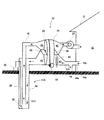
図1は、この発明の第1の実施の形態のデシカント空調システムを示すもので、被空調空間10を形成する建物12の近傍に設置された地中熱交換器14と、室内(被空調空間)10からの環気RAを処理空気として取り入れて地中熱交換器14に導く導入経路16と、地中熱交換器14において熱交換して冷却された空気を被空調空間10に供給するための供給経路18と、これら導入経路16及び供給経路18の双方に跨ってこれらを遮るように配置されたデシカントロータ20を用いるデシカント除湿装置22と、これらの経路に空気を送風する送風機24とを有している。
Embodiments of the present invention will be described below with reference to the drawings.
FIG. 1 shows a desiccant air-conditioning system according to a first embodiment of the present invention. An
デシカント空調システムは、円筒状あるいは円盤状の内部空間を形成するケーシング34の中に構成され、デシカントロータ20はこのケーシング34内に回転自在に配置されている。ケーシング34内の空間は、仕切板36によって軸線を含む面で上下に区分され、一方は導入経路16に連通して、デシカントロータ20を導入空気によって再生する(デシカントロータ20の水分を脱着する)再生ゾーン40となる。また、他方の空間は、供給経路18に連絡され、デシカントロータ20により供給空気を除湿する(デシカントロータ20に水分を吸着させる)吸着ゾーン42となる。デシカントロータ20の他方の側(デシカントロータに対して導入経路又は供給経路とは反対の側)は密閉されている。デシカントロータ20には、これを所定の速度で回転させる駆動モータ38が設けられている。
The desiccant air conditioning system is configured in a
デシカントロータ20としては、所定の多孔質なデシカント(吸着剤)を、ハニカム状補強構造を有する円盤状部材に成形した周知のものを採用することができる。デシカントの素材としては、アクリル基を有する機能性有機系収着剤またはシリカゲルまたは活性炭などのように、相対湿度が70乃至100%の領域で吸脱着量の差が大きい素材が望ましく、更には相対湿度が高い領域において防カビ性や抗菌性が高い素材(例えばアクリル基を有する機能性有機系収着剤)が望ましい。
As the
地中熱交換器14は、例えば熱伝導性の良い銅やアルミニウム等の金属製若しくは合成樹脂製の管を地中に深さ20乃至100メートル程度埋設して形成された循環型の熱媒体流路50を備えており、ポンプ52の動作により水などの熱媒体が、地中と地上の間で循環するようになっている。この熱媒体流路の地上部分は、ケーシング34内の二次側の空間に導入されて、処理空気と熱交換を行う気液熱交換部54となっている。この気液熱交換部54は、接触面積を増やすために蛇行した配管となっており、凝縮した水分を導くための排水管56が導出されている。
The
この実施の形態では、導入経路16の入口、すなわち空気取入口44の内側に、デシカントロータ20と対向するように遠赤外線ヒータ(加熱手段)46が設けられている。これは、外気の相対湿度が高い場合、すなわち、絶対湿度が高いか温度が低い場合に用いるもので、必要に応じて設置すればよい。この場合、被空調空間10に湿度センサを設置し、検出した湿度が高い時に、この遠赤外線ヒータ46をオンにするようにしてもよい。また、別の加熱手段として、デシカントロータ20に適当なヒータを埋設し、その部分が導入経路16側に有る時にオンにするようにしてもよい。さらに、デシカントロータ20の上流に加熱手段として温水と熱交換させる熱交換器を設け、温水の加熱源として、太陽熱コレクタで集めた熱を用いるようにしてもよい。
In this embodiment, a far-infrared heater (heating means) 46 is provided at the inlet of the
また、図示しないが、周知の制御手段を設け、被空調空間等に設置した各種センサ等を用いて種々の運転制御を行うことができる。例えば、デシカント空調システムをマニュアルモードと自動モードの双方で運転できるようにし、自動モードでは、被空調空間に設置した湿度センサが検出した湿度(相対湿度、露点温度又は絶対湿度)が設定した許容上限値より高い時にデシカントロータ20を回転させ、検出した湿度が設定した許容値より低い時にデシカントロータ20を停止させるようにする。
Moreover, although not shown in figure, a known control means is provided and various operation control can be performed using the various sensors etc. which were installed in the to-be-conditioned space. For example, the desiccant air conditioning system can be operated in both manual mode and automatic mode. In the automatic mode, the allowable upper limit set by the humidity (relative humidity, dew point temperature or absolute humidity) detected by the humidity sensor installed in the air-conditioned space is set. The
以下、上記のように構成されたデシカント空調システムを用いて、室内の空気を循環させながら除湿・冷房運転をする場合の動作を、図2の湿り空気線図を参照して説明する。なお、以下の説明における温度、湿度その他の数値は例示的なものである。
図2において、室内10からの環気RAはAの状態であり、例えば相対湿度が80%程度である。相対湿度が高いので遠赤外線ヒータ46がオンとなり、デシカントロータ20の再生ゾーン40の表面を加熱し、ここを通過する導入空気がデシカントと接触する際、例えば相対湿度が70%程度となる状態Bになるように加熱する。もし、還気RAの相対湿度が70%程度である場合には、遠赤外線ヒータ46は作動せず、状態Bからスタートする。
Hereinafter, the operation in the case of performing dehumidification / cooling operation while circulating indoor air using the desiccant air conditioning system configured as described above will be described with reference to the humid air diagram of FIG. In addition, the temperature, humidity, and other numerical values in the following description are illustrative.
In FIG. 2, the atmospheric air RA from the
加熱された状態Bの導入空気は、デシカントロータ20を通過する際にこれから水分を脱着し、この際に等エンタルピ変化して、相対湿度がほぼ100%の状態Cに変化する。状態Cの導入空気は、さらに地中熱交換器14に送られて、気液熱交換部54において20℃近傍まで冷却され、飽和線に沿って水分を結露分離させて絶対湿度が低下し、状態Dに至る。この時、気液熱交換部では状態Cから状態Dまで所謂濡れ面熱伝達が行われ、極めて高い熱通過率で空気と地中との熱交換が行われる。
The heated introduced air in the state B desorbs moisture from it when passing through the
温度と絶対湿度が低下した状態Dの空気は、除湿ゾーン42においてデシカントロータ20を通過し、水分を吸着されることにより除湿され、ほぼ要求露点温度15℃に相当する状態Eとなり、供給経路18を介して室内に供給される。なお、上記の説明は状態変化が理想変化であることを仮定したもので、実際には、Bは湿度70%の等相対湿度線より下になり、Eが等相対湿度線より上になる。
The air in the state D in which the temperature and the absolute humidity are reduced passes through the
このように、このデシカント空調システムは、地中熱という1つの自然熱源のみを用いて冷却と除湿を行うので、別途冷熱源や空調設備を必要とせず、省エネルギー、省コストでかつ環境に配慮した空調システムが提供される。また、空気の経路が1系統であるので、送風機24も1つで済み、全体の構成が簡単であるので、設備コストも小さく、建物の中間階にも容易に設置できる等のメリットも有る。
In this way, this desiccant air conditioning system uses only one natural heat source called geothermal heat for cooling and dehumidification, so there is no need for a separate cooling heat source or air conditioning equipment, and it is energy-saving, cost-saving and environmentally friendly. An air conditioning system is provided. Further, since there is only one air path, only one
また、この実施の形態では、遠赤外線ヒータ46を用いることで、その輻射熱により脱着空気入口側のデシカントロータ20を乾燥させてから、除湿経路に回転移動するため、処理空気からの水分吸着量が増加し、熱損失が少ないという利点が有る。なお、状態A〜状態Bでの加熱温度は低いため、太陽熱や低温排熱が利用でき、それによってさらなる省エネルギー効果、及びエコロジー効果を得ることもできる。
In this embodiment, the far-
図3は、この発明の第2の実施の形態のデシカント空調システムを示すもので、基本的な構成は先の実施の形態と同じであるので、詳しい説明を省略し、また、対応する構成は同じ符号で示す。この実施の形態が先の実施の形態と異なるのは、熱媒体流路50の熱媒体の一部を分岐させた分岐配管58を、供給経路18に配置した冷房熱交換器60に導いている点である。これにより、図2に状態E→状態Fの経路で示すように、デシカントロータ20で除湿した際に昇温した空気の温度を低下させて室内に供給し、冷房効果を高めている。また、この実施の形態では、予熱用の遠赤外線ヒータ64に、太陽電池62からの電力を導入して、省エネルギー効果を高めている。
FIG. 3 shows a desiccant air-conditioning system according to a second embodiment of the present invention. Since the basic configuration is the same as that of the previous embodiment, detailed description is omitted, and the corresponding configuration is as follows. It shows with the same code | symbol. This embodiment is different from the previous embodiment in that a
図4は、この発明の第3の実施の形態のデシカント空調システムを示すもので、外気を処理して室内空間に供給するものである。そして、地中熱交換器14Aは、空気を直接地中に導く形式であり、例えば熱伝導性の良い銅やアルミニウム等の金属製の二重管から構成されている。二重管は、地中に深さ5乃至10メートル程度埋設され、その底部近傍の温度は15℃程度に保たれている。内管26は外管28の底面より上で開口しており、内管26の内外を上下に往復する空気流路が構成され、内外の空気流路はほぼ等断面積になるように設定されている。この例では、外管28は導入経路16に内管26は供給経路18にそれぞれ連絡している。外管28の底部には結露水を排水溝30に排出するための排水ポンプ32が設置されている。
FIG. 4 shows a desiccant air conditioning system according to a third embodiment of the present invention, which processes outside air and supplies it to the indoor space. The
図示例では、地中熱交換器14Aは1基が設置されているが、通常は、空調すべき空間10の大きさに応じて複数が設置される。複数の地中熱交換器14Aは、デシカント除湿装置22に対して並列に接続される。この場合、状況に応じて動作台数を設定するように、開閉弁を設置して、使用する地中熱交換器14Aの数を選択することができるようにしてもよい。もちろん、それぞれの地中熱交換器14Aに個別にデシカント除湿装置22を設置するようにしてもよい。なお、地中熱交換器14Aの設置個所は建物の外側でも内側でもよい。
In the illustrated example, one
先の実施の形態と同様に、地上には、円筒状あるいは円盤状の内部空間を形成するケーシング34が設置され、このケーシング34内にデシカント除湿装置22が構成されている。デシカント除湿装置22は、回転自在に配置されたデシカントロータ20と、デシカントロータ20の前後の内部空間を軸線を含む面で区分して2つの部分空間を構成する仕切板36と、デシカントロータ20を所定の回転速度で回転駆動するモータ38を有している。2つの部分空間の一方は、導入経路16に連絡され、デシカントロータ20を導入空気によって再生する(デシカントロータ20の水分を脱着する)再生ゾーン40となる。また、他方の部分空間は、供給経路18に連絡され、デシカントロータ20により供給空気を除湿する(デシカントロータ20に水分を吸着させる)除湿ゾーン42となる。
As in the previous embodiment, a
先の実施の形態と同様に、デシカントロータ20としては、所定の多孔質なデシカント(吸着剤)を、ハニカム状補強構造を有する円盤状部材に成形した周知のものを採用することができる。デシカントの素材としては、アクリル基を有する機能性有機系収着剤またはシリカゲルまたは活性炭などのように、相対湿度が70乃至100%の領域で吸脱着量の差が大きい素材が望ましく、更には相対湿度が高い領域において防カビ性や抗菌性が高い素材(例えばアクリル基を有する機能性有機系収着剤)が望ましい。
As in the previous embodiment, as the
先の実施の形態と同様に、導入経路16の入口、すなわち空気取入口44の内側に、デシカントロータ20と対向するように遠赤外線ヒータ(加熱手段)46が設けられている。これは、外気の相対湿度が高い場合、すなわち、絶対湿度が高いか温度が低い場合に用いるもので、必要に応じて設置すればよい。この場合、外部空間に湿度センサを設置し、検出した湿度が高い時に、この遠赤外線ヒータ46をオンにするようにしてもよい。また、別の加熱手段として、デシカントロータ20に適当なヒータを埋設し、その部分が導入経路16側に有る時にオンにするようにしてもよい。さらに、デシカントロータ20の上流に加熱手段として温水と熱交換させる熱交換器を設け、温水の加熱源として、太陽熱コレクタで集めた熱を用いるようにしてもよい。
As in the previous embodiment, a far-infrared heater (heating means) 46 is provided at the inlet of the
また、周知の制御手段を設け、被空調空間等に設置した各種センサ等を用いて種々の運転制御を行うことができる。例えば、デシカント空調システムをマニュアルモードと自動モードの双方で運転できるようにし、自動モードでは、被空調空間に設置した湿度センサが検出した湿度(相対湿度、露点温度又は絶対湿度)が設定した許容上限値より高い時にデシカントロータ20を回転させ、検出した湿度が設定した許容値より低い時にデシカントロータ20を停止させるようにする。
Moreover, a known control means is provided, and various operation controls can be performed using various sensors installed in the air-conditioned space. For example, the desiccant air conditioning system can be operated in both manual mode and automatic mode. In the automatic mode, the allowable upper limit set by the humidity (relative humidity, dew point temperature or absolute humidity) detected by the humidity sensor installed in the air-conditioned space is set. The
以下、上記のように構成されたデシカント空調システムの動作を、図5の湿り空気線図を参照して説明する。なお、以下の説明における温度、湿度その他の数値は例示的なものである。 Hereinafter, the operation of the desiccant air conditioning system configured as described above will be described with reference to the wet air diagram of FIG. In addition, the temperature, humidity, and other numerical values in the following description are illustrative.
図5において、外気はAの状態であり、例えば相対湿度が80%程度である。相対湿度が高いので遠赤外線ヒータ46がオンとなり、デシカントロータ20の再生ゾーン40の表面を加熱し、ここを通過する導入空気がデシカントと接触する際、例えば相対湿度が70%程度となる状態Bになるように加熱する。この導入空気は、デシカントロータ20を通過する際にこれから水分を脱着し、この際に等エンタルピ変化して、相対湿度がほぼ100%の状態Cに変化する。状態Cの導入空気は、さらに地中熱交換器14Aに送られて20℃近傍まで冷却され、飽和線に沿って水分を結露分離させて絶対湿度が低下し、状態Dに至る。この時、地中熱熱交換器では状態Cから状態Dまで所謂濡れ面熱伝達が行われ、極めて高い熱通過率で空気と地中との熱交換が行われる。
In FIG. 5, the outside air is in the state A, and the relative humidity is about 80%, for example. When the far-
温度と絶対湿度が低下した状態Dの空気は、除湿ゾーン42においてデシカントロータ20を通過し、水分を吸着されることにより除湿され、ほぼ要求露点温度15℃に相当する状態Eとなり、供給経路18を介して室内に供給される。なお、上記の説明は状態変化が理想変化であることを仮定したもので、実際には、Bは湿度70%の等相対湿度線より下になり、Eが等相対湿度線より上になる。
上記において、外気の相対湿度が70%よりも低い場合には、遠赤外線ヒータ46はオフのままで、上記のサイクルが実行される。
The air in the state D in which the temperature and the absolute humidity are reduced passes through the
In the above, when the relative humidity of the outside air is lower than 70%, the far
このように、このデシカント空調システムは、地中熱という1つの自然熱源のみを用いて冷却と除湿を行うので、別途冷熱源や空調設備を必要とせず、省エネルギー、省コストでかつ環境に配慮した空調システムが提供される。また、空気の経路が1系統であるので、送風機24も1つで済み、全体の構成が簡単であるので、設備コストも小さく、建物の中間階にも容易に設置できる等のメリットも有る。
In this way, this desiccant air conditioning system uses only one natural heat source called geothermal heat for cooling and dehumidification, so there is no need for a separate cooling heat source or air conditioning equipment, and it is energy-saving, cost-saving and environmentally friendly. An air conditioning system is provided. Further, since there is only one air path, only one
また、この実施の形態では、遠赤外線ヒータ46を用いることで、その輻射熱により脱着空気入口側のデシカントロータ20を乾燥させてから、除湿経路に回転移動するため、処理空気からの水分吸着量が増加し、熱損失が少ないという利点が有る。なお、状態A〜状態Bでの加熱温度は低いため、太陽熱や低温排熱が利用でき、それによってさらなる省エネルギー効果、及びエコロジー効果を得ることもできる。
In this embodiment, the far-
図6はこの発明の他の実施の形態を示すもので、このデシカント空調システムは、外気ではなく、室内からの還気を冷却・除湿した後、室内に再度供給するように構成されている。また、図7はその動作を説明するための湿り空気線図である。図4の実施の形態では、室内空気が外気で換気されるので、室内空間の衛生環境は維持されるが、処理の負荷は大きくなる。一方、この実施の形態では、より相対湿度の低い室内空気を処理空気とすることで、処理負荷を軽減し、処理空気出口の到達湿度(絶対湿度)を低くする作用が得られるが、換気機能については別途考慮する必要が有る。 FIG. 6 shows another embodiment of the present invention, and this desiccant air-conditioning system is configured to supply the indoor air again after cooling and dehumidifying the return air from the room, not the outside air. FIG. 7 is a moist air diagram for explaining the operation. In the embodiment of FIG. 4, since the indoor air is ventilated with the outside air, the sanitary environment of the indoor space is maintained, but the processing load increases. On the other hand, in this embodiment, the processing air is reduced by using indoor air having a lower relative humidity as the processing air, and the effect of reducing the ultimate humidity (absolute humidity) at the processing air outlet can be obtained. Need to be considered separately.
この実施の形態の動作は、先の実施の形態の場合と、処理空気の初期状態Aが異なるだけで、基本的に同じである。加熱手段(遠赤外線ヒータ)は、先の場合と同様に、導入する室内空気の相対湿度が高い場合、すなわち、絶対湿度が高いか温度が低い場合に用いるので、必要に応じて設置すればよい。この場合、加熱手段の動作を制御するための温度又は湿度センサは、室内に設ける。 The operation of this embodiment is basically the same as that of the previous embodiment, except that the initial state A of the processing air is different. As in the previous case, the heating means (far infrared heater) is used when the relative humidity of the indoor air to be introduced is high, that is, when the absolute humidity is high or the temperature is low. . In this case, a temperature or humidity sensor for controlling the operation of the heating means is provided indoors.
図8はこの発明の他の実施の形態を示すもので、このデシカント空調システムは、外気と室内にそれぞれ開口する空気取入口44a,44bを設けており、外気と室内還気の双方を取り入れて、冷却・除湿した後、室内に再度供給するように構成されている。このように、還気と外気を混合して処理空気とすることで、図4の実施の形態の換気作用と、図6の実施の形態の処理負荷の軽減作用と、処理空気出口の到達湿度(絶対湿度)を低くする作用を同時に達成することができる。
FIG. 8 shows another embodiment of the present invention. This desiccant air conditioning system is provided with
また、図9はその動作を説明するための湿り空気線図である。動作は、先の実施の形態の場合と、処理空気の初期状態Aが異なるだけで、基本的に同じであるので、説明は省略する。 FIG. 9 is a moist air diagram for explaining the operation. The operation is basically the same as that of the previous embodiment except that the initial state A of the processing air is different, and the description thereof will be omitted.
図10は、この発明の他の実施の形態を示すもので、外気と室内からの還気の双方を必要に応じて取り入れることができるように、各取入口44a,44bに開閉ダンパ48a,48bを設けたものである。各開閉ダンパ48a,48bの開閉を制御することにより、上述した3つの実施の形態のいずれのパターンの動作も可能である。
FIG. 10 shows another embodiment of the present invention. Opening and
10 被空調空間
12 建物
14,14A 地中熱交換器
16 導入経路
18 供給経路
20 デシカントロータ
22 デシカント除湿装置
24 送風機
26 内管
28 外管
30 排水溝
32 排水ポンプ
34 ケーシング
36 仕切板
38 モータ
40 再生ゾーン
42 除湿ゾーン
44,44a,44b 空気取入口
46 遠赤外線ヒータ
48a,48b 開閉ダンパ
50 熱媒体流路
52 ポンプ
54 気液熱交換部
56 排水管
58 分岐配管
60 冷房熱交換器
62 太陽電池
64 遠赤外線ヒータ
DESCRIPTION OF
Claims (4)
地中熱交換器で冷却された処理空気を被空調空間に導く供給経路と、
これら導入経路及び供給経路の双方に跨って配置されたデシカントロータを備え、
前記デシカントロータをその各部が前記導入経路と供給経路に順次位置するように回転させることにより、冷却後の処理空気を該デシカントロータで除湿し、かつ冷却前の処理空気でデシカントロータを再生するようにしたことを特徴とするデシカント空調システム。 An introduction path for guiding the processing air to the underground heat exchanger;
A supply path for guiding the processing air cooled by the underground heat exchanger to the air-conditioned space;
It has a desiccant rotor arranged across both the introduction route and the supply route,
By rotating the desiccant rotor so that each part is sequentially positioned in the introduction path and the supply path, the desiccant rotor is dehumidified by the desiccant rotor, and the desiccant rotor is regenerated by the process air before cooling. Desiccant air conditioning system characterized by
The desiccant air conditioning system according to any one of claims 1 to 3, wherein a heat medium flow path for flowing a heat medium in the ground is used as the underground heat exchanger.
Priority Applications (4)
| Application Number | Priority Date | Filing Date | Title |
|---|---|---|---|
| JP2006133837A JP4816231B2 (en) | 2005-10-07 | 2006-05-12 | Desiccant air conditioning system |
| EP06018736A EP1772681A3 (en) | 2005-10-07 | 2006-09-07 | A desiccant air-conditioning system |
| US11/521,021 US20070079623A1 (en) | 2005-10-07 | 2006-09-14 | Desiccant air-conditioning system |
| CN200610141362.8A CN1945141B (en) | 2005-10-07 | 2006-09-29 | Desiccant air-conditioning system |
Applications Claiming Priority (3)
| Application Number | Priority Date | Filing Date | Title |
|---|---|---|---|
| JP2005294547 | 2005-10-07 | ||
| JP2005294547 | 2005-10-07 | ||
| JP2006133837A JP4816231B2 (en) | 2005-10-07 | 2006-05-12 | Desiccant air conditioning system |
Publications (2)
| Publication Number | Publication Date |
|---|---|
| JP2007127400A JP2007127400A (en) | 2007-05-24 |
| JP4816231B2 true JP4816231B2 (en) | 2011-11-16 |
Family
ID=37607167
Family Applications (1)
| Application Number | Title | Priority Date | Filing Date |
|---|---|---|---|
| JP2006133837A Active JP4816231B2 (en) | 2005-10-07 | 2006-05-12 | Desiccant air conditioning system |
Country Status (4)
| Country | Link |
|---|---|
| US (1) | US20070079623A1 (en) |
| EP (1) | EP1772681A3 (en) |
| JP (1) | JP4816231B2 (en) |
| CN (1) | CN1945141B (en) |
Families Citing this family (25)
| Publication number | Priority date | Publication date | Assignee | Title |
|---|---|---|---|---|
| NL1032450C2 (en) * | 2006-09-06 | 2008-03-07 | Uptime Technology B V | Device and method for cooling a space in a data center with the aid of recirculation air. |
| CN101715535B (en) | 2007-04-30 | 2012-01-11 | 奥西库尔有限公司 | Motor cycle air conditioning system |
| JP5089254B2 (en) * | 2007-06-11 | 2012-12-05 | 新日本空調株式会社 | Humidity conditioning air conditioning system for automobiles |
| US7654101B2 (en) * | 2007-12-07 | 2010-02-02 | Shapiro Ian M | Split-air stream air conditioning with desiccant dehumidification |
| US7836723B2 (en) * | 2008-06-10 | 2010-11-23 | The United States Of America As Represented By The Secretary Of The Navy | Air conditioning system |
| US20100043462A1 (en) | 2008-06-10 | 2010-02-25 | Oxicool, Inc. | Air Conditioning System |
| US20110004350A1 (en) * | 2009-07-01 | 2011-01-06 | Indie Energy Systems Company | Renewable thermal energy metering and controls system |
| SE536313E (en) | 2009-07-13 | 2016-06-07 | Skanska Kommersiell Utveckling Norden Ab | A method of cooling comprising a rock layer |
| JP2011085270A (en) * | 2009-10-13 | 2011-04-28 | Yamatake Corp | Desiccant air conditioning system and method of operating the same |
| WO2011062554A1 (en) * | 2009-11-19 | 2011-05-26 | Airwatergreen Ab | Device and method for absorbing water from gas |
| US8434239B2 (en) * | 2010-01-14 | 2013-05-07 | James Zoucha | Method and means for drying grain in a storage bin |
| GB2481003A (en) * | 2010-06-07 | 2011-12-14 | David Stenhouse | Recycled water storage system for vehicle windscreen cleaning |
| US8943848B2 (en) | 2010-06-16 | 2015-02-03 | Reznor Llc | Integrated ventilation unit |
| US20120090808A1 (en) * | 2010-10-18 | 2012-04-19 | Alcatel-Lucent Usa, Incorporated | Liquid cooling of remote or off-grid electronic enclosures |
| CN102435033B (en) * | 2011-12-01 | 2014-05-14 | 国家电网公司 | Closed type circulation water cooling device and method thereof |
| CN103404954A (en) * | 2013-06-25 | 2013-11-27 | 大丰市佳丰油脂有限责任公司 | Method and special device for processing cottonseed meal which is cooked and pre-squeezed in process of production |
| KR101594422B1 (en) * | 2013-12-31 | 2016-02-17 | 한국과학기술연구원 | Solar energy dehumidifying and cooling air system |
| WO2015192249A1 (en) | 2014-06-20 | 2015-12-23 | Nortek Air Solutions Canada, Inc. | Systems and methods for managing conditions in enclosed space |
| US11092349B2 (en) | 2015-05-15 | 2021-08-17 | Nortek Air Solutions Canada, Inc. | Systems and methods for providing cooling to a heat load |
| SG10201913923WA (en) | 2015-05-15 | 2020-03-30 | Nortek Air Solutions Canada Inc | Using liquid to air membrane energy exchanger for liquid cooling |
| US10834855B2 (en) | 2016-01-08 | 2020-11-10 | Nortek Air Solutions Canada, Inc. | Integrated make-up air system in 100% air recirculation system |
| JP2018165607A (en) * | 2017-03-28 | 2018-10-25 | 東新住建株式会社 | Air conditioning device for building |
| GB2576515B (en) * | 2018-08-21 | 2022-05-18 | Ebac Industrial Products Ltd | Desiccant dehumidifier |
| KR102538132B1 (en) * | 2021-03-16 | 2023-05-31 | 주식회사 휴마스터 | Dehumidifying system |
| KR102559533B1 (en) * | 2021-05-31 | 2023-07-26 | 주식회사 휴마스터 | Thermo hygrostat and control method thereof |
Family Cites Families (21)
| Publication number | Priority date | Publication date | Assignee | Title |
|---|---|---|---|---|
| US4367631A (en) * | 1980-06-16 | 1983-01-11 | Harold R. Johnson | Air conditioning apparatus and methods using underground duct |
| JPS57150743A (en) * | 1981-03-12 | 1982-09-17 | Adachi Jimusho:Kk | Cooling and heating device with terrestrial heat |
| JPS5837432A (en) * | 1981-08-31 | 1983-03-04 | Matsushita Electric Works Ltd | Underground imbedded pipe |
| JPS6075858U (en) * | 1983-10-27 | 1985-05-28 | 工業技術院長 | underground heat exchange equipment |
| JP2624291B2 (en) * | 1988-04-08 | 1997-06-25 | 松下電器産業株式会社 | Far infrared heater |
| JP2524299B2 (en) * | 1993-04-30 | 1996-08-14 | 株式会社オーエム研究所 | Handling box for solar system house |
| CN1103156A (en) * | 1993-11-25 | 1995-05-31 | 肖国雄 | Air conditioning method and device using underground heat (cold) |
| CH691349A5 (en) * | 1995-03-16 | 2001-07-13 | Gunnar Ankarstig | Continuous drying of air to low dew point comprises combining refrigeration circuit with regenerative sorption dehumidifier |
| JPH09318127A (en) * | 1996-05-24 | 1997-12-12 | Ebara Corp | Air-conditioning system |
| JPH11262621A (en) * | 1998-03-17 | 1999-09-28 | Ebara Corp | Dehumidifying air conditioner |
| WO2000000774A1 (en) * | 1998-06-30 | 2000-01-06 | Ebara Corporation | Heat exchanger, heat pump, dehumidifier, and dehumidifying method |
| US6178762B1 (en) * | 1998-12-29 | 2001-01-30 | Ethicool Air Conditioners, Inc. | Desiccant/evaporative cooling system |
| US6138744A (en) * | 1999-06-07 | 2000-10-31 | Coffee; Derek A. | Closed loop geothermal heat exchanger |
| US6575228B1 (en) * | 2000-03-06 | 2003-06-10 | Mississippi State Research And Technology Corporation | Ventilating dehumidifying system |
| DE20103857U1 (en) * | 2001-03-06 | 2001-05-31 | TUHH Technologie GmbH, 21079 Hamburg | Device for sorption-based air conditioning of room air |
| JP2004092956A (en) * | 2002-08-30 | 2004-03-25 | Shin Nippon Air Technol Co Ltd | Desiccant air conditioning method and desiccant air conditioner |
| KR100504489B1 (en) * | 2002-12-26 | 2005-08-03 | 엘지전자 주식회사 | air conditioner |
| JP2005009737A (en) * | 2003-06-18 | 2005-01-13 | Matsushita Electric Ind Co Ltd | Soil heat utilizing air conditioning system |
| JP4696482B2 (en) * | 2003-07-03 | 2011-06-08 | パナソニック株式会社 | Dehumidifier |
| CN1281899C (en) * | 2004-05-13 | 2006-10-25 | 上海交通大学 | Hybrid dehumidifying air-conditioner |
| WO2005123225A1 (en) * | 2004-06-17 | 2005-12-29 | Matsushita Electric Industrial Co., Ltd. | Dehumidifier |
-
2006
- 2006-05-12 JP JP2006133837A patent/JP4816231B2/en active Active
- 2006-09-07 EP EP06018736A patent/EP1772681A3/en not_active Withdrawn
- 2006-09-14 US US11/521,021 patent/US20070079623A1/en not_active Abandoned
- 2006-09-29 CN CN200610141362.8A patent/CN1945141B/en not_active Expired - Fee Related
Also Published As
| Publication number | Publication date |
|---|---|
| EP1772681A3 (en) | 2008-07-30 |
| JP2007127400A (en) | 2007-05-24 |
| CN1945141B (en) | 2010-04-21 |
| US20070079623A1 (en) | 2007-04-12 |
| CN1945141A (en) | 2007-04-11 |
| EP1772681A2 (en) | 2007-04-11 |
Similar Documents
| Publication | Publication Date | Title |
|---|---|---|
| JP4816231B2 (en) | Desiccant air conditioning system | |
| KR101746154B1 (en) | Air conditioning system | |
| JP4816267B2 (en) | Humidity control device | |
| US7305849B2 (en) | Sorptive heat exchanger and related cooled sorption process | |
| KR100675802B1 (en) | An apparatus to remove or humidity moisture | |
| CN203928192U (en) | The air-conditioner outdoor unit with air pretreatment function | |
| JP3992051B2 (en) | Air conditioning system | |
| JP5497492B2 (en) | Desiccant air conditioner | |
| CA2984840C (en) | Reverse flow dehumidifier and methods of operating the same | |
| CN103717976A (en) | Humidity controller and air conditioning system | |
| KR100795101B1 (en) | Desiccant appartus, air conditioning apparatus and system having the same | |
| JP6178174B2 (en) | Desiccant air conditioner and desiccant air conditioner | |
| KR102538252B1 (en) | Air conditioner and the method thereof | |
| CN103140273B (en) | Moisture trap and dehumanization method | |
| KR20200092221A (en) | An air conditioning system | |
| KR102180663B1 (en) | Air conditioner and the method thereof | |
| JP6532270B2 (en) | Low temperature regeneration desiccant air conditioner | |
| JP6898138B2 (en) | Desiccant type humidity control device and its control method | |
| JP6321212B2 (en) | Dehumidifying and cooling device | |
| JP6348987B2 (en) | Hybrid heat pump device | |
| JP5332534B2 (en) | Air conditioner | |
| JP6854099B2 (en) | Humidity control ventilation system | |
| CN2911508Y (en) | Humidifying, dehumidifying, energy saving ventilator used for indoor or place | |
| JP2005164220A (en) | Air conditioner | |
| JP6188438B2 (en) | Air conditioner and operation method thereof |
Legal Events
| Date | Code | Title | Description |
|---|---|---|---|
| A521 | Request for written amendment filed |
Free format text: JAPANESE INTERMEDIATE CODE: A523 Effective date: 20060516 |
|
| A621 | Written request for application examination |
Free format text: JAPANESE INTERMEDIATE CODE: A621 Effective date: 20081126 |
|
| A131 | Notification of reasons for refusal |
Free format text: JAPANESE INTERMEDIATE CODE: A131 Effective date: 20110413 |
|
| TRDD | Decision of grant or rejection written | ||
| A01 | Written decision to grant a patent or to grant a registration (utility model) |
Free format text: JAPANESE INTERMEDIATE CODE: A01 Effective date: 20110802 |
|
| A01 | Written decision to grant a patent or to grant a registration (utility model) |
Free format text: JAPANESE INTERMEDIATE CODE: A01 |
|
| A61 | First payment of annual fees (during grant procedure) |
Free format text: JAPANESE INTERMEDIATE CODE: A61 Effective date: 20110815 |
|
| FPAY | Renewal fee payment (event date is renewal date of database) |
Free format text: PAYMENT UNTIL: 20140909 Year of fee payment: 3 |
|
| R150 | Certificate of patent or registration of utility model |
Ref document number: 4816231 Country of ref document: JP Free format text: JAPANESE INTERMEDIATE CODE: R150 Free format text: JAPANESE INTERMEDIATE CODE: R150 |
|
| FPAY | Renewal fee payment (event date is renewal date of database) |
Free format text: PAYMENT UNTIL: 20140909 Year of fee payment: 3 |
|
| R250 | Receipt of annual fees |
Free format text: JAPANESE INTERMEDIATE CODE: R250 |
|
| R250 | Receipt of annual fees |
Free format text: JAPANESE INTERMEDIATE CODE: R250 |
|
| R250 | Receipt of annual fees |
Free format text: JAPANESE INTERMEDIATE CODE: R250 |
|
| R250 | Receipt of annual fees |
Free format text: JAPANESE INTERMEDIATE CODE: R250 |
|
| R250 | Receipt of annual fees |
Free format text: JAPANESE INTERMEDIATE CODE: R250 |
|
| R250 | Receipt of annual fees |
Free format text: JAPANESE INTERMEDIATE CODE: R250 |
|
| R250 | Receipt of annual fees |
Free format text: JAPANESE INTERMEDIATE CODE: R250 |
|
| R250 | Receipt of annual fees |
Free format text: JAPANESE INTERMEDIATE CODE: R250 |
|
| R250 | Receipt of annual fees |
Free format text: JAPANESE INTERMEDIATE CODE: R250 |
|
| R250 | Receipt of annual fees |
Free format text: JAPANESE INTERMEDIATE CODE: R250 |