JP4801669B2 - Method and apparatus for using an advanced host controller interface to transfer data - Google Patents
Method and apparatus for using an advanced host controller interface to transfer data Download PDFInfo
- Publication number
- JP4801669B2 JP4801669B2 JP2007532461A JP2007532461A JP4801669B2 JP 4801669 B2 JP4801669 B2 JP 4801669B2 JP 2007532461 A JP2007532461 A JP 2007532461A JP 2007532461 A JP2007532461 A JP 2007532461A JP 4801669 B2 JP4801669 B2 JP 4801669B2
- Authority
- JP
- Japan
- Prior art keywords
- host controller
- command
- data
- test mode
- bit
- Prior art date
- Legal status (The legal status is an assumption and is not a legal conclusion. Google has not performed a legal analysis and makes no representation as to the accuracy of the status listed.)
- Expired - Fee Related
Links
Images


Classifications
-
- G—PHYSICS
- G06—COMPUTING; CALCULATING OR COUNTING
- G06F—ELECTRIC DIGITAL DATA PROCESSING
- G06F13/00—Interconnection of, or transfer of information or other signals between, memories, input/output devices or central processing units
- G06F13/38—Information transfer, e.g. on bus
- G06F13/382—Information transfer, e.g. on bus using universal interface adapter
- G06F13/385—Information transfer, e.g. on bus using universal interface adapter for adaptation of a particular data processing system to different peripheral devices
Description
本発明の実施形態は、コンピュータシステムにおいてデータを転送する技術分野に関し、特に、データをアドバンスドホストコントローラインタフェース(AHCI)で交換することに関する。 Embodiments of the present invention relate to the technical field of transferring data in a computer system, and more particularly to exchanging data with an Advanced Host Controller Interface (AHCI).
CD ROM、ハードディスクドライブ、DVD RAM等のシリアルアドバンスドテクノロジアタッチメント(SATA)デバイスを、2004年4月13日に発行されたSerial ATA Host Controller Interface(AHCI) Specification, Revision 1.0に準拠するホストコントローラ(HC)を有するコンピュータシステムに焦点を合せた方法で開発することができる。AHCI Specificationは、この仕様を実装し且つSATAデバイスとコンピュータシステムのメモリとの間のインタフェースとしての役割を果たすデバイスについて記述している。このインタフェースデバイスは、たとえばホストコントローラ、ホストバストアダプタ等として知られている。このデバイスは仕様によって記述されているため、事前に設定されたコマンド及び手続きに応答するよう期待される。 Serial Advanced Technology Attachment (SATA) devices such as CD ROM, hard disk drive, DVD RAM, etc. are converted into a host controller (Serial ATA Host Controller Interface (AHCI) Specification, Revision 1.0, issued April 13, 2004). HC) can be developed in a way that focuses on the computer system. AHCI Specification describes a device that implements this specification and serves as an interface between the SATA device and the memory of the computer system. This interface device is known as, for example, a host controller or a host bust adapter. Since this device is described by specification, it is expected to respond to pre-configured commands and procedures.
たとえば、HCは通常データ交換に先立ってSATAデバイスにコマンドを送信する。そして、HCは、データ交換が行われることが可能になる前に応答を待つ。しかしながら、HCのデータを交換する能力をテストすることは、通常HCをテストしている時、SATAデバイスは通常存在しないため、困難となる。その結果、HCがコマンドを送信し、存在しないデバイスからの応答を待つことは無駄である。 For example, the HC normally sends a command to the SATA device prior to data exchange. The HC then waits for a response before data exchange can take place. However, testing the ability to exchange HC data is difficult because there is usually no SATA device when testing HC. As a result, it is useless for the HC to send a command and wait for a response from a non-existing device.
本発明の実施形態を、以下の説明と、かかる実施形態を例証する添付の図面とを参照することによって、最もよく理解することができる。 Embodiments of the invention can best be understood by referring to the following description and the accompanying drawings that illustrate such embodiments.
以下の記述では、本発明が完全に理解されるために、説明の目的で多数の特定の詳細を示す。しかしながら、当業者には、本発明の実施形態をこれらの特定の詳細なしに実施してもよいということが明らかとなろう。 In the following description, for the purposes of explanation, numerous specific details are set forth in order to provide a thorough understanding of the present invention. However, it will be apparent to those skilled in the art that embodiments of the invention may be practiced without these specific details.
本発明の実施形態により、データ交換のための状態機械シーケンスの複数の状態を省略することが可能になり、ここでは、HCは一動作のモードに入る。一実施形態では、HCは、データを交換する要求を受信し、このデータを交換する要求は、データを送信する要求であっても、又はデータを受信する要求であってもよい。したがって、ビットが、そのモードに入る時にクリアされ、デバイスによって受信されるべきコマンドを送信する前の状態機械の後続する状態においてセットされる。デバイスによって受信されるべきコマンドを送信する前にビットをセットすることにより、HCは、データ送信又は受信の前に通常実行される状態を省略することができる。一実施形態によれば、HCは、アドバンスドホストコントローラインタフェースHCである。 Embodiments of the present invention make it possible to omit multiple states of the state machine sequence for data exchange, where the HC enters a mode of operation. In one embodiment, the HC receives a request to exchange data, and the request to exchange data may be a request to send data or a request to receive data. Thus, the bit is cleared when entering that mode and set in the subsequent state of the state machine prior to sending the command to be received by the device. By setting a bit before sending a command to be received by the device, the HC can omit the state normally performed before sending or receiving data. According to one embodiment, the HC is an advanced host controller interface HC.
したがって、後により詳細に説明するように、本発明の実施形態は、HCのデータ交換で実行されるべき動作を低減することにより、ホストコントローラをテストする能力を向上させることができる。 Thus, as will be described in more detail later, embodiments of the present invention can improve the ability to test the host controller by reducing the operations to be performed in the HC data exchange.
図1Aは、ホストコントローラテストデバイス(テストデバイス)52に接続されているホストコントローラ(HC)50を示す。HC50は、SATAインタフェース58によってテストデバイス52に接続される。このインタフェースは、HC50に対し、テストデバイス52と通信する能力を提供する任意の適当なインタフェースであってもよい。さらに、テストデバイス52は、HCをテストするために必要な機能を提供することができる任意の適当なデバイスであってもよい。
FIG. 1A shows a host controller (HC) 50 connected to a host controller test device (test device) 52. The HC 50 is connected to the
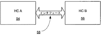
図1Bは、第1のホストコントローラ(HC−A)54が第2のホストコントローラ(HC−B)56に接続される、代替のテスト構成を示す。HCを、上述したように、任意の適当なインタフェースによって接続することができる。2つのHCを互いに接続することにより、コンピュータシステムを、ホストコントローラのデータ送受信をテストするために使用することができる。 FIG. 1B shows an alternative test configuration in which a first host controller (HC-A) 54 is connected to a second host controller (HC-B) 56. The HCs can be connected by any suitable interface as described above. By connecting the two HCs together, the computer system can be used to test host controller data transmission and reception.
本発明の実施形態を、図1A及び図1Bに示す構成においてホストコントローラによって実施することができる。ホストコントローラの他の適当な構成があり得るため、図1A及び図1Bの構成は限定するためではなく例として提供する。 Embodiments of the present invention can be implemented by a host controller in the configuration shown in FIGS. 1A and 1B. Because there may be other suitable configurations of the host controller, the configurations of FIGS. 1A and 1B are provided by way of example and not limitation.
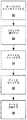
図2は、一実施形態による、HCとデータを交換するプロセスを説明するフローチャートを示す。プロセスブロック60において、HCは一モードに入る。本発明の一実施形態では、このモードは、HCをテストするモードであってもよい。さらに、一実施形態では、モードは特に、このモードにおけるHCによるデータ送信又はデータ受信をテストすることであってもよい。HCは、コンピュータシステムメモリ26に格納されているソフトウェア命令から指示されることに応じてそのモードに入ってもよい。HCはまた、図1A又は図1Bに示すもののようなHCに接続されている外部デバイスからHCによって受信される命令を通してそのモードに入ってもよい。HCのモードに入る実施形態は、上述したプロセスによって限定されない。さらに、実施形態は、HCデバイスドライバを使用して、モード及び/又は変更をHCに設定することができる。
FIG. 2 shows a flowchart describing a process for exchanging data with HC, according to one embodiment. In
一実施形態では、HCは、モードに入ると(プロセスブロック60)、HCがビジーでないことを示すようにビットをクリアする。より詳細には、ビットを、HCが目下動作を実行していないことを指定するようにクリアする。一実施形態では、たとえば、モードに入る時、PxTFD.STS.BSYビット(BSYビット)をクリアする。この一実施形態では、BSYビットは、HCの、SATAデバイスとデータを交換する能力に関する、タスクファイルデータの現ステータスを示す特定のレジスタビットである。 In one embodiment, when the HC enters the mode (process block 60), it clears the bit to indicate that the HC is not busy. More specifically, the bit is cleared to specify that the HC is not currently performing an operation. In one embodiment, for example, when entering mode, PxTFD. STS. Clear the BSY bit (BSY bit). In this embodiment, the BSY bit is a specific register bit that indicates the current status of the task file data with respect to the HC's ability to exchange data with the SATA device.
次に、HCは、HCがデータを交換するためにデバイスに発行するコマンドを選択する(プロセスブロック62)。そして、HCは、選択されたコマンドに対してコマンドヘッダをフェッチする(プロセスブロック64)。一実施形態では、コマンドの選択を、システム10等のコンピュータシステムにより、又は図1A及び図1Bに示すような外部ハードウェアデバイス等によりトリガしてもよい。 The HC then selects a command that the HC issues to the device to exchange data (process block 62). Then, the HC fetches a command header for the selected command (process block 64). In one embodiment, command selection may be triggered by a computer system, such as system 10, or by an external hardware device as shown in FIGS. 1A and 1B.
通常、HCは、コマンドヘッダをフェッチした後(プロセスブロック64)、コマンドがデバイスに発行される用意ができるまで、アイドル状態のままである。しかしながら、一実施形態では、コマンドヘッダをフェッチした後、HCがビジーである、すなわち動作を実行していることを示すようにビットをセットする(プロセスブロック66)。一実施形態では、システムがビジーであることを示すように、BSYビットをセットする。システムがビジーであることを示すようにビットをセットすることにより、HCはデータの交換に進む(プロセスブロック68)。データ交換は、データ送信であってもデータ受信であってもよい。 Normally, the HC remains idle after fetching the command header (process block 64) until the command is ready to be issued to the device. However, in one embodiment, after fetching the command header, a bit is set to indicate that the HC is busy, ie performing an operation (process block 66). In one embodiment, the BSY bit is set to indicate that the system is busy. By setting the bit to indicate that the system is busy, the HC proceeds to exchange data (process block 68). The data exchange may be data transmission or data reception.
HCがビジーであることを示すようにビットがセットされると(プロセスブロック66)、HCは、SATAデバイスにコマンドを送信しない。またHCは、コマンドが正しく送信されたという確認応答を受信する必要もない。さらに、ビットをセットすることにより、HCはまた、SATAデバイスがデータを受け入れる用意ができるのを待つ必要もなく、且つSATAデバイスがデータを受信する用意ができているという確認応答を待つ必要もない。代りに、HCはデータ交換に進む。 If the bit is set to indicate that the HC is busy (process block 66), the HC will not send a command to the SATA device. Also, the HC does not need to receive an acknowledgment that the command has been sent correctly. Furthermore, by setting the bit, the HC also does not have to wait for the SATA device to be ready to accept data, nor does it need to wait for an acknowledgment that the SATA device is ready to receive data. . Instead, the HC proceeds to data exchange.
HCは、ビットがセットされると直接データ交換に進むため、データ送信及び/又はデータ受信のために状態機械シーケンスの状態を省略する。一実施形態では、このモードでデータを送信する時、HCは、状態機械シーケンスの以下の状態、すなわち、コマンドフレーム情報構造送信(Command Frame Information Structure Transmit)(CFIS:Xmit)、コマンドフレーム情報構造成功(Command Frame Information Structure Success)(CFIS:Success)、ホストアイドル(Host Idle)(H:Idle)、非データフレーム情報構造受信エントリ(Non-Data Frame Information Structure Receive Entry)(NDR:Entry)及び非データフレーム情報構造受信受入(Non-Data Frame Information Structure Receive Accept)(NDR:Accept)のうちの少なくとも1つ又は複数を省略する。代替の実施形態では、他の状態及びプロセスを省略してもよい。このため、一実施形態によれば、HCがそのモードにある時にデータ送信ための状態機械シーケンスは、H:Idle、H:SelectCmd、H:FetchCmd、H:Idle、DX:Entry及びDX:Transmitとなる。一実施形態によれば、H:Idleが、ホストコントローラが非アクティブである状態を指す場合、データ送信のために状態機械シーケンスの第2のH:Idle状態に入ると、ビットがセットされる。 Since the HC proceeds directly to data exchange when the bit is set, it omits the state of the state machine sequence for data transmission and / or data reception. In one embodiment, when transmitting data in this mode, the HC is in the following states of the state machine sequence: Command Frame Information Structure Transmit (CFIS: Xmit), Command Frame Information Structure Success (Command Frame Information Structure Success) (CFIS: Success), Host Idle (H: Idle), Non-Data Frame Information Structure Receive Entry (NDR: Entry), and non-data At least one or more of Non-Data Frame Information Structure Receive Accept (NDR: Accept) is omitted. In alternative embodiments, other states and processes may be omitted. Thus, according to one embodiment, the state machine sequences for data transmission when the HC is in that mode are H: Idle, H: SelectCmd, H: FetchCmd, H: Idle, DX: Entry and DX: Transmit. Become. According to one embodiment, if H: Idle refers to a state where the host controller is inactive, the bit is set upon entering the second H: Idle state of the state machine sequence for data transmission.
同様に、そのモードにおいてデータを受信する場合、HCは、一実施形態によれば、以下の状態、すなわち、CFIS:Xmit、CFIS:Success及びH:Idleのうちの少なくとも1つ又は複数を省略する。このため、データ受信のための状態機械シーケンスは、H:Idle、H:SelectCmd、H:FetchCmd、H:Idle、DR:Entry及びDR:Receiveとなる。代替の実施形態では、他の状態及びプロセスを省略してもよい。一実施形態によれば、データ受信のために状態機械シーケンスの第2のH:Idle状態に入ると、ビットがセットされる。 Similarly, when receiving data in that mode, the HC, according to one embodiment, omits at least one or more of the following states: CFIS: Xmit, CFIS: Success and H: Idle. . Therefore, the state machine sequence for data reception is H: Idle, H: SelectCmd, H: FetchCmd, H: Idle, DR: Entry, and DR: Receive. In alternative embodiments, other states and processes may be omitted. According to one embodiment, the bit is set upon entering the second H: Idle state of the state machine sequence for data reception.
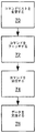
図3は、本発明の代替の実施形態実施形態による、HCとデータを交換するプロセスを説明するフローチャートを示す。この実施形態によれば、HCデバイスドライバ及び拡張HCは、上述したように、データ交換のための状態及びプロセスを省略することによってデータを交換することができる。図3に示すように、AHCIデバイスドライバは、HCによって受信されるコマンドリストの内容を変更する(プロセスブロック70)。コマンドリストには、コマンドフレーム情報構造(Command Frame Information Structure)(CFIS)が、対応するコマンドフレーム情報構造長(CFL)とともに含まれる。AHCIデバイスドライバは、CFLをゼロにセットする。CFL=0をセットすることにより、拡張ホストコントローラはCFISを処理しない。その結果、ホストコントローラは、HCに接続されているデバイスにコマンドを送信することなく、且つコマンドが受信されたとデバイスが確認応答するのを待つことなく、データを交換することができる。 FIG. 3 shows a flowchart describing a process for exchanging data with HCs according to an alternative embodiment of the present invention. According to this embodiment, as described above, the HC device driver and the extended HC can exchange data by omitting the state and process for data exchange. As shown in FIG. 3, the AHCI device driver changes the contents of the command list received by the HC (process block 70). The command list includes a command frame information structure (CFIS) together with a corresponding command frame information structure length (CFL). The AHCI device driver sets CFL to zero. By setting CFL = 0, the extended host controller does not process CFIS. As a result, the host controller can exchange data without sending a command to the device connected to the HC and without waiting for the device to acknowledge that the command has been received.
CFLがゼロにセットされた後、HCは、図2に示す実施形態に関してHCが行ったように、データを交換するコマンドを選択し(プロセスブロック72)、コマンドヘッダをフェッチすることができる(プロセスブロック74)。しかしながら、図2に示す実施形態とは異なり、図3の実施形態は、HCがコマンドヘッダをフェッチした後にビットをセットする必要はない。CFL=0である場合、HCは、デバイスにコマンドを送信せず、デバイスによってコマンドが受信されたという確認応答も待たない。その代わり、コマンドヘッダがフェッチされた後、HCは、CFL=0である時にデータ交換に進む(プロセスブロック76)。 After CFL is set to zero, the HC can select a command to exchange data (process block 72) and fetch the command header (process block), as HC did for the embodiment shown in FIG. Block 74). However, unlike the embodiment shown in FIG. 2, the embodiment of FIG. 3 does not require a bit to be set after the HC fetches the command header. If CFL = 0, the HC does not send a command to the device and does not wait for an acknowledgment that the command has been received by the device. Instead, after the command header is fetched, the HC proceeds to data exchange when CFL = 0 (process block 76).
こうした実施形態により、HCをテストする能力を向上させることができる。図3に示す実施形態によれば、本方法により、テストHCによってコマンドを送信及び/又は受信する柔軟性が可能になる。さらに、こうした実施形態は、ソフトウェア及び/又はハードウェアが種々のコマンドを実行する場合にHCをテストする柔軟な方法を提供する。一実施形態によれば、任意選択でCFL=0とセットすることにより、いくつかのコマンドのみがCFISがテストデバイスに送信されるよう要求する、コマンドの混合が可能になる。 Such an embodiment can improve the ability to test HC. According to the embodiment shown in FIG. 3, the method allows the flexibility to send and / or receive commands by the test HC. Furthermore, such embodiments provide a flexible way to test the HC when software and / or hardware executes various commands. According to one embodiment, optionally setting CFL = 0 allows a mixture of commands that require only some commands to be sent to the test device by the CFIS.
図4は、一実施形態による、本明細書で説明した装置及び方法を実施するシステム10を示す。システム10の文脈で説明するが、実施形態を任意の適当なコンピュータシステムで実施してもよい。 FIG. 4 illustrates a system 10 that implements the apparatus and methods described herein, according to one embodiment. Although described in the context of the system 10, embodiments may be implemented on any suitable computer system.
図4に示すように、コンピュータシステム10は、少なくとも1つのHC24を備える。コンピュータシステム10はまた、メモリ26及び入出力コントローラハブ(ICH)28も備える。プロセッサ22、メモリ26、HC(複数可)24及びICH28は、メモリコントローラハブ48に接続される。ICH28は、ハブリンク20を介してメモリコントローラハブに接続される。別法として、HC(複数可)34を、さらにメモリコントローラハブ48に接続するか又はそれに統合してもよい。
As shown in FIG. 4, the computer system 10 includes at least one
システムメモリ26は、コンピュータシステム10のためのデータ及び/又は命令を格納するものであり、たとえばダイナミックランダムアクセスメモリ(DRAM)、シンクロナスダイナミックランダムアクセスメモリ(SDRAM)又は拡張データ出力ランダムアクセスメモリ(EDO RAM)等の任意の適当なメモリを含んでもよい。コンピュータシステム10は、たとえばブラウン管(CRT)又は液晶ディスプレイ(LCD)等のディスプレイ32に接続されたグラフィックスコントローラ30をさらに備える。
The
ICH28は、コンピュータシステム10に、I/Oデバイス又は周辺コンポーネントに対するインタフェースを提供する。ICH28は、プロセッサ22及びメモリ26に他の任意の適当な通信リンクを提供するために任意の適当なインタフェースコントローラ(複数可)を備えてもよい。ICH28はまた、たとえばマウス、キーボード、フロッピーディスクドライブ及び/又は他の任意の適当なI/Oデバイス等のI/Oデバイス(複数可)44に対するインタフェースも提供する。ICH28はまた、パラレルアドバンスドテクノロジアタッチメント(PATA)デバイス38及び/又はユニバーサルシリアルバス(USB)デバイス40等のデバイスのための代替のインタフェースを提供してもよい。
The
HC(複数可)24及び34は、データ及び/又は命令を格納及び/又は検索するために、たとえばハードディスクドライブ(HDD)、コンパクトディスクリードオンリメモリ(CD ROM)、デジタルビデオディスクリードオンリメモリ(DVD ROM)等、任意の適当なSATAデバイス(複数可)36及び/又は46に、プロセッサ22及びメモリ26に対するインタフェースを提供する。
The HC (s) 24 and 34 may be used to store and / or retrieve data and / or instructions, for example, a hard disk drive (HDD), a compact disk read only memory (CD ROM), a digital video disk read only memory (DVD). Any suitable SATA device (s) 36 and / or 46, such as a ROM, may provide an interface to the
システムメモリ26は、一実施形態によれば、本明細書で論考したようなプロセス及び状態を省略することによってHCをテストする命令42をさらに含む。代替の実施形態では、命令を、コンピュータシステム10内のファームウェア、コンピュータシステム10内の専用回路等に含めることができるため、それらの命令はメモリ26に存在する必要はない。
The
したがって、コンピュータシステム10は、本明細書で説明した方法のうちの任意の1つ又はすべてを具現化する命令のセット(すなわちソフトウェア)が格納される機械読取可能媒体を含む。たとえば、ソフトウェアは、完全に又は少なくとも部分的にメモリ26内に且つ/又はプロセッサ22内に存在してもよい。この明細書の目的では、「機械読取可能媒体」という用語は、情報を機械(たとえばコンピュータ)によって読取可能な形態で提供する(すなわち、格納、検索及び/又は送信する)任意のメカニズムを含むように解釈されるものとする。たとえば、機械読取可能媒体は、読み出し専用メモリ(ROM)、ランダムアクセスメモリ(RAM)、磁気ディスク記憶媒体、光記憶媒体、フラッシュメモリデバイス、電気、光、音響又は他の形態の伝播信号(たとえば搬送波、赤外線信号、デジタル信号等)等を含む。
Accordingly, the computer system 10 includes a machine-readable medium on which a set of instructions (ie, software) that embodies any one or all of the methods described herein is stored. For example, the software may reside completely or at least partially in the
本発明を、特定の実施形態例を参照して説明したが、本発明のより広い精神及び範囲から逸脱することなく、これらの実施形態に対してさまざまな変更及び変形を行ってもよいということが明らかとなろう。したがって、本明細書及び図面は、限定する意味ではなく例示する意味で考慮されるべきである。 Although the invention has been described with reference to specific example embodiments, it will be understood that various changes and modifications may be made to these embodiments without departing from the broader spirit and scope of the invention. Will be clear. The specification and drawings are, accordingly, to be regarded in an illustrative sense rather than a restrictive sense.
Claims (9)
前記ホストコントローラが前記テストモード中において、
前記ホストコントローラがビジーでないことを示すようにビットをクリアすること、
データを交換するための第1のコマンドを受信すること、
前記ホストコントローラがビジーであることを示すように前記ビットをセットすること、
前記第1のコマンドに対応してデータを交換すること、
を含み、
前記テストモード中の前記ホストコントローラの状態機械シーケンスは、前記テストモードではない場合にホストコントローラインタフェース仕様により要求される、記憶デバイスに第2のコマンドを送信するための状態を省略すること
を含む方法。To enter the test mode of the host controller, and,
While the host controller is in the test mode,
Clearing the bit to indicate that the host controller is not busy;
Receiving a first command for exchanging data;
Setting the bit to indicate that the host controller is busy;
Exchanging data in response to the first command;
Including
The state machine sequence of the host controller during the test mode includes omitting the state for sending a second command to the storage device as required by the host controller interface specification when not in the test mode .
前記ホストコントローラが前記テストモードの間に、ビジービットをクリアする手段と、
前記ホストコントローラが前記テストモードの間に、データを交換するための要求の第1のコマンドを受信する手段と、
前記ホストコントローラが前記テストモードの間に、前記第1のコマンドを受信した後に前記ビジービットをセットする手段と、
前記ホストコントローラがテストモードの間に、前記第1のコマンドに応答して前記ホストコントローラがデータを交換する手段と
を備え、
テストモード中における前記ホストコントローラの状態機械シーケンスは、前記ホストコントローラが前記テストモードでない場合にホストコントローラインタフェース仕様により要求される、記憶装置に第2のコマンドを送信するための状態を省略する装置。And the means to enter the test mode of the host controller,
Means for clearing a busy bit while the host controller is in the test mode;
Means for receiving a first command of a request to exchange data while the host controller is in the test mode ;
Means for setting the busy bit after the host controller receives the first command during the test mode;
Means for the host controller to exchange data in response to the first command while the host controller is in a test mode;
With
The state machine sequence of the host controller during the test mode is a device that omits the state for sending the second command to the storage device, which is required by the host controller interface specification when the host controller is not in the test mode .
前記第2のコマンドが正しく送信されたという確認応答の受信を省略する手段をさらに含む、請求項5に記載の装置。 The host controller
6. The apparatus of claim 5 , further comprising means for omitting receipt of an acknowledgment that the second command has been transmitted correctly.
データを交換するための第1のコマンドをフェッチし、
前記ホストコントローラがテストモードでない場合に前記ホストコントローラが実行するようにホストコントローラインタフェース仕様により要求される状態機械シーケンスである、記憶デバイスに第2のコマンドの送信することを、事前に行うことなく、前記ホストコントローラにより前記データを交換することを、前記テストモードにおいて実行するホストコントローラ
を具備する装置。 Clear the bit indicating that the host controller is not busy,
Fetches the first command for exchanging data,
Sending a second command to the storage device, which is a state machine sequence required by the host controller interface specification to be executed by the host controller when the host controller is not in test mode, without performing in advance , to exchange the data by the host controller, device comprising a host controller to run in the test mode.
Applications Claiming Priority (3)
| Application Number | Priority Date | Filing Date | Title |
|---|---|---|---|
| US10/948,803 US20060075164A1 (en) | 2004-09-22 | 2004-09-22 | Method and apparatus for using advanced host controller interface to transfer data |
| US10/948,803 | 2004-09-22 | ||
| PCT/US2005/032933 WO2006036572A2 (en) | 2004-09-22 | 2005-09-13 | A method and apparatus for using advanced host controller interface to transfer data |
Related Child Applications (1)
| Application Number | Title | Priority Date | Filing Date |
|---|---|---|---|
| JP2011037206A Division JP2011146058A (en) | 2004-09-22 | 2011-02-23 | Method and apparatus for using advanced host controller interface to transfer data |
Publications (2)
| Publication Number | Publication Date |
|---|---|
| JP2008513889A JP2008513889A (en) | 2008-05-01 |
| JP4801669B2 true JP4801669B2 (en) | 2011-10-26 |
Family
ID=35925204
Family Applications (2)
| Application Number | Title | Priority Date | Filing Date |
|---|---|---|---|
| JP2007532461A Expired - Fee Related JP4801669B2 (en) | 2004-09-22 | 2005-09-13 | Method and apparatus for using an advanced host controller interface to transfer data |
| JP2011037206A Withdrawn JP2011146058A (en) | 2004-09-22 | 2011-02-23 | Method and apparatus for using advanced host controller interface to transfer data |
Family Applications After (1)
| Application Number | Title | Priority Date | Filing Date |
|---|---|---|---|
| JP2011037206A Withdrawn JP2011146058A (en) | 2004-09-22 | 2011-02-23 | Method and apparatus for using advanced host controller interface to transfer data |
Country Status (6)
| Country | Link |
|---|---|
| US (1) | US20060075164A1 (en) |
| JP (2) | JP4801669B2 (en) |
| CN (1) | CN101014942B (en) |
| DE (1) | DE112005002254T5 (en) |
| TW (1) | TWI311722B (en) |
| WO (1) | WO2006036572A2 (en) |
Families Citing this family (15)
| Publication number | Priority date | Publication date | Assignee | Title |
|---|---|---|---|---|
| US7603514B2 (en) * | 2005-03-31 | 2009-10-13 | Intel Corporation | Method and apparatus for concurrent and independent data transfer on host controllers |
| US7464228B2 (en) * | 2006-05-31 | 2008-12-09 | Dell Products L.P. | System and method to conserve conventional memory required to implement serial ATA advanced host controller interface |
| US7827320B1 (en) * | 2008-03-28 | 2010-11-02 | Western Digital Technologies, Inc. | Serial ATA device implementing intra-command processing by detecting XRDY primitive while in the XRDY state |
| US8856390B1 (en) * | 2008-03-28 | 2014-10-07 | Western Digital Technologies, Inc. | Using device control field to implement non-disruptive notification of an ATA device |
| US8327040B2 (en) | 2009-01-26 | 2012-12-04 | Micron Technology, Inc. | Host controller |
| US8291125B2 (en) * | 2011-02-16 | 2012-10-16 | Smsc Holdings S.A.R.L. | Speculative read-ahead for improving system throughput |
| US10209768B1 (en) * | 2012-01-06 | 2019-02-19 | Seagate Technology Llc | File-aware priority driver |
| US9268692B1 (en) | 2012-04-05 | 2016-02-23 | Seagate Technology Llc | User selectable caching |
| US9542324B1 (en) | 2012-04-05 | 2017-01-10 | Seagate Technology Llc | File associated pinning |
| US9116694B2 (en) | 2012-09-26 | 2015-08-25 | Intel Corporation | Efficient low power exit sequence for peripheral devices |
| US9141563B2 (en) * | 2013-09-11 | 2015-09-22 | Kabushiki Kaisha Toshiba | Memory system |
| US9632711B1 (en) | 2014-04-07 | 2017-04-25 | Western Digital Technologies, Inc. | Processing flush requests by utilizing storage system write notifications |
| US9645752B1 (en) | 2014-04-07 | 2017-05-09 | Western Digital Technologies, Inc. | Identification of data committed to non-volatile memory by use of notification commands |
| KR101936950B1 (en) | 2016-02-15 | 2019-01-11 | 주식회사 맴레이 | Computing device, data transfer method between coprocessor and non-volatile memory, and program including the same |
| EP3891594A4 (en) * | 2019-05-05 | 2022-08-10 | Yangtze Memory Technologies Co., Ltd. | Memory control system with a sequence processing unit |
Citations (2)
| Publication number | Priority date | Publication date | Assignee | Title |
|---|---|---|---|---|
| JP2001229120A (en) * | 2000-02-18 | 2001-08-24 | Sharp Corp | Process error dtection method for chain type dma, and dma controller |
| WO2002095556A1 (en) * | 2001-05-18 | 2002-11-28 | Fujitsu Limited | Apparatus having stand-by mode, program, and control method for apparatus having stand-by mode |
Family Cites Families (29)
| Publication number | Priority date | Publication date | Assignee | Title |
|---|---|---|---|---|
| US4183084A (en) * | 1977-06-06 | 1980-01-08 | Digital Equipment Corporation | Secondary storage facility with serial transfer of control messages |
| US5438674A (en) * | 1988-04-05 | 1995-08-01 | Data/Ware Development, Inc. | Optical disk system emulating magnetic tape units |
| US5293491A (en) * | 1990-12-28 | 1994-03-08 | International Business Machines Corp. | Data processing system and memory controller for lock semaphore operations |
| US5598579A (en) * | 1994-04-25 | 1997-01-28 | Compaq Computer Corporation | System fpr transferring data between two buses using control registers writable by host processor connected to system bus and local processor coupled to local bus |
| US5659718A (en) * | 1994-08-19 | 1997-08-19 | Xlnt Designs, Inc. | Synchronous bus and bus interface device |
| US6467054B1 (en) * | 1995-03-13 | 2002-10-15 | Compaq Computer Corporation | Self test for storage device |
| US5802392A (en) * | 1995-07-20 | 1998-09-01 | Future Domain Corporation | System for transferring 32-bit double word IDE data sequentially without an intervening instruction by automatically incrementing I/O port address and translating incremented address |
| US6055583A (en) * | 1997-03-27 | 2000-04-25 | Mitsubishi Semiconductor America, Inc. | DMA controller with semaphore communication protocol |
| US6026448A (en) * | 1997-08-27 | 2000-02-15 | International Business Machines Corporation | Method and means for exchanging messages, responses and data between different computer systems that require a plurality of communication paths between them |
| US6009488A (en) * | 1997-11-07 | 1999-12-28 | Microlinc, Llc | Computer having packet-based interconnect channel |
| US6708233B1 (en) * | 1999-03-25 | 2004-03-16 | Microsoft Corporation | Method and apparatus for direct buffering of a stream of variable-length data |
| US6631431B1 (en) * | 1999-09-15 | 2003-10-07 | Koninklijke Philips Electronics N.V. | Semaphore coding method to ensure data integrity in a can microcontroller and a can microcontroller that implements this method |
| US6609171B1 (en) * | 1999-12-29 | 2003-08-19 | Intel Corporation | Quad pumped bus architecture and protocol |
| US6622189B2 (en) * | 2000-11-30 | 2003-09-16 | International Business Machines Corporation | Method and system for low overhead spin lock instrumentation |
| US6799233B1 (en) * | 2001-06-29 | 2004-09-28 | Koninklijke Philips Electronics N.V. | Generalized I2C slave transmitter/receiver state machine |
| US6889265B2 (en) * | 2001-11-05 | 2005-05-03 | Intel Corporation | Apparatus and method to allow and synchronize schedule changes in a USB enhanced host controller |
| US6961787B2 (en) * | 2002-01-07 | 2005-11-01 | Intel Corporation | Method and apparatus for updating task files |
| TW569013B (en) * | 2002-02-21 | 2004-01-01 | Via Tech Inc | Chip test method for testing host controller of universal serial bus |
| US20040010625A1 (en) * | 2002-07-09 | 2004-01-15 | Silicon Integrated Systems Corp. | Interface device and method for transferring data over serial ATA |
| DE10239814B4 (en) * | 2002-08-29 | 2008-06-05 | Advanced Micro Devices, Inc., Sunnyvale | Extended test mode support for host controllers |
| US7072989B1 (en) * | 2002-09-27 | 2006-07-04 | Cypress Semiconductor, Inc. | USB peripheral device storing an indication of an operating power mode when a host went into hibernate and restarting at the power mode accordingly |
| US6901461B2 (en) * | 2002-12-31 | 2005-05-31 | Intel Corporation | Hardware assisted ATA command queuing |
| US6810443B2 (en) * | 2002-12-31 | 2004-10-26 | Intel Corporation | Optical storage transfer performance |
| US7010711B2 (en) * | 2003-06-25 | 2006-03-07 | Lsi Logic Corporation | Method and apparatus of automatic power management control for native command queuing Serial ATA device |
| US7149823B2 (en) * | 2003-08-29 | 2006-12-12 | Emulex Corporation | System and method for direct memory access from host without processor intervention wherein automatic access to memory during host start up does not occur |
| US7206973B2 (en) * | 2003-12-11 | 2007-04-17 | Lsi Logic Corporation | PCI validation |
| JP3736642B2 (en) * | 2004-01-22 | 2006-01-18 | セイコーエプソン株式会社 | Data transfer control device and electronic device |
| US20050216611A1 (en) * | 2004-03-29 | 2005-09-29 | Martinez Alberto J | Method and apparatus to achieve data pointer obfuscation for content protection of streaming media DMA engines |
| US7577772B2 (en) * | 2004-09-08 | 2009-08-18 | Qlogic, Corporation | Method and system for optimizing DMA channel selection |
-
2004
- 2004-09-22 US US10/948,803 patent/US20060075164A1/en not_active Abandoned
-
2005
- 2005-09-13 DE DE112005002254T patent/DE112005002254T5/en not_active Withdrawn
- 2005-09-13 WO PCT/US2005/032933 patent/WO2006036572A2/en active Application Filing
- 2005-09-13 JP JP2007532461A patent/JP4801669B2/en not_active Expired - Fee Related
- 2005-09-13 CN CN2005800304468A patent/CN101014942B/en not_active Expired - Fee Related
- 2005-09-15 TW TW094131834A patent/TWI311722B/en active
-
2011
- 2011-02-23 JP JP2011037206A patent/JP2011146058A/en not_active Withdrawn
Patent Citations (2)
| Publication number | Priority date | Publication date | Assignee | Title |
|---|---|---|---|---|
| JP2001229120A (en) * | 2000-02-18 | 2001-08-24 | Sharp Corp | Process error dtection method for chain type dma, and dma controller |
| WO2002095556A1 (en) * | 2001-05-18 | 2002-11-28 | Fujitsu Limited | Apparatus having stand-by mode, program, and control method for apparatus having stand-by mode |
Also Published As
| Publication number | Publication date |
|---|---|
| DE112005002254T5 (en) | 2007-08-23 |
| TWI311722B (en) | 2009-07-01 |
| WO2006036572A2 (en) | 2006-04-06 |
| TW200627287A (en) | 2006-08-01 |
| WO2006036572A3 (en) | 2006-08-24 |
| CN101014942A (en) | 2007-08-08 |
| JP2008513889A (en) | 2008-05-01 |
| US20060075164A1 (en) | 2006-04-06 |
| CN101014942B (en) | 2010-05-05 |
| JP2011146058A (en) | 2011-07-28 |
Similar Documents
| Publication | Publication Date | Title |
|---|---|---|
| JP4801669B2 (en) | Method and apparatus for using an advanced host controller interface to transfer data | |
| US7069350B2 (en) | Data transfer control system, electronic instrument, and data transfer control method | |
| US6442628B1 (en) | Method and system for automatically determining maximum data throughput over a bus | |
| JP2011146058A5 (en) | ||
| US7620747B1 (en) | Software based native command queuing | |
| EP2423822B1 (en) | Methods and apparatus for improved serial advanced technology attachment performance | |
| US6233632B1 (en) | Optimizing peripheral component interconnect transactions in a mixed 32/64-bit environment by eliminating unnecessary data transfers | |
| JP4412191B2 (en) | Data transfer control device and electronic device | |
| US6948025B2 (en) | System and method for transferring data between an IEEE 1394 device and a SCSI device | |
| US20140281041A1 (en) | Facilitating transport mode data transfer between a channel subsystem and input/output devices | |
| TWI416339B (en) | Usb transaction translator and an isochronous-in transaction method | |
| US6301631B1 (en) | Memory mapping method for eliminating dual address cycles in a peripheral component interconnect environment | |
| US7051148B2 (en) | Data transmission sequencing method associated with briding device and application system | |
| JP2001337911A (en) | Usb-atapi interface system and atapi-usb converter used for it | |
| US6178478B1 (en) | Smart target mechanism for eliminating dual address cycles in a peripheral component interconnect environment | |
| JP2000132507A (en) | Command processing method for scsi protocol and device used for the processing method | |
| TWI411922B (en) | Universal serial bus host controller and method utilizing the same | |
| JP5291311B2 (en) | USB storage system and data transfer control program | |
| JPH0623967B2 (en) | Device disconnection method | |
| JP2006301810A (en) | Data transfer processing method, data transfer processor and data transfer processing control program | |
| US7028131B1 (en) | Reverse message writes and reads | |
| JP2008009804A (en) | Information processor and information processing method, information processing system, program and recording medium | |
| JPH06309245A (en) | Scsi interface system device | |
| JP2006330968A (en) | Serial data transmission/reception method and serial data transmission/reception device | |
| JPH06324961A (en) | Communication control equipment |
Legal Events
| Date | Code | Title | Description |
|---|---|---|---|
| A131 | Notification of reasons for refusal |
Free format text: JAPANESE INTERMEDIATE CODE: A131 Effective date: 20091215 |
|
| A601 | Written request for extension of time |
Free format text: JAPANESE INTERMEDIATE CODE: A601 Effective date: 20100312 |
|
| A602 | Written permission of extension of time |
Free format text: JAPANESE INTERMEDIATE CODE: A602 Effective date: 20100319 |
|
| A601 | Written request for extension of time |
Free format text: JAPANESE INTERMEDIATE CODE: A601 Effective date: 20100414 |
|
| A602 | Written permission of extension of time |
Free format text: JAPANESE INTERMEDIATE CODE: A602 Effective date: 20100421 |
|
| A521 | Written amendment |
Free format text: JAPANESE INTERMEDIATE CODE: A523 Effective date: 20100510 |
|
| A131 | Notification of reasons for refusal |
Free format text: JAPANESE INTERMEDIATE CODE: A131 Effective date: 20100824 |
|
| A601 | Written request for extension of time |
Free format text: JAPANESE INTERMEDIATE CODE: A601 Effective date: 20101122 |
|
| A602 | Written permission of extension of time |
Free format text: JAPANESE INTERMEDIATE CODE: A602 Effective date: 20101130 |
|
| A601 | Written request for extension of time |
Free format text: JAPANESE INTERMEDIATE CODE: A601 Effective date: 20101222 |
|
| A602 | Written permission of extension of time |
Free format text: JAPANESE INTERMEDIATE CODE: A602 Effective date: 20110111 |
|
| A601 | Written request for extension of time |
Free format text: JAPANESE INTERMEDIATE CODE: A601 Effective date: 20110121 |
|
| A602 | Written permission of extension of time |
Free format text: JAPANESE INTERMEDIATE CODE: A602 Effective date: 20110128 |
|
| A521 | Written amendment |
Free format text: JAPANESE INTERMEDIATE CODE: A523 Effective date: 20110223 |
|
| TRDD | Decision of grant or rejection written | ||
| A01 | Written decision to grant a patent or to grant a registration (utility model) |
Free format text: JAPANESE INTERMEDIATE CODE: A01 Effective date: 20110719 |
|
| A01 | Written decision to grant a patent or to grant a registration (utility model) |
Free format text: JAPANESE INTERMEDIATE CODE: A01 |
|
| A61 | First payment of annual fees (during grant procedure) |
Free format text: JAPANESE INTERMEDIATE CODE: A61 Effective date: 20110805 |
|
| FPAY | Renewal fee payment (event date is renewal date of database) |
Free format text: PAYMENT UNTIL: 20140812 Year of fee payment: 3 |
|
| R150 | Certificate of patent or registration of utility model |
Free format text: JAPANESE INTERMEDIATE CODE: R150 |
|
| R250 | Receipt of annual fees |
Free format text: JAPANESE INTERMEDIATE CODE: R250 |
|
| R250 | Receipt of annual fees |
Free format text: JAPANESE INTERMEDIATE CODE: R250 |
|
| LAPS | Cancellation because of no payment of annual fees |