JP4795809B2 - Seat reclining device - Google Patents
Seat reclining device Download PDFInfo
- Publication number
- JP4795809B2 JP4795809B2 JP2006043523A JP2006043523A JP4795809B2 JP 4795809 B2 JP4795809 B2 JP 4795809B2 JP 2006043523 A JP2006043523 A JP 2006043523A JP 2006043523 A JP2006043523 A JP 2006043523A JP 4795809 B2 JP4795809 B2 JP 4795809B2
- Authority
- JP
- Japan
- Prior art keywords
- locking
- seat back
- seat
- lock
- reclining device
- Prior art date
- Legal status (The legal status is an assumption and is not a legal conclusion. Google has not performed a legal analysis and makes no representation as to the accuracy of the status listed.)
- Expired - Fee Related
Links
Images


Description
本発明は、車両用シート等のシートを構成するシートバックの傾斜角を適宜調節するために使用されるリクライニング装置の改良に関する。 The present invention relates to an improvement of a reclining device used for appropriately adjusting an inclination angle of a seat back constituting a seat such as a vehicle seat.
例えばワンボックスカー等のように、少なくとも1列の後部座席を有する従来の自動車の中には、前部座席のシートバックを前倒して後部座席に乗降する必要があるものがある。この場合、前部座席のシートクッションに対するシートバックの傾斜角を調節するためのリクライニング装置を前部座席の側部あるいは後部に設けられたレバーを操作することによりシートバックのロックを解除してシートバックを前倒するようにしている。 Some conventional automobiles having at least one row of rear seats, such as a one-box car, need to get on and off the rear seats with the seat back of the front seats moved forward. In this case, the reclining device for adjusting the inclination angle of the seat back with respect to the seat cushion of the front seat is operated by operating a lever provided on the side portion or the rear portion of the front seat to release the seat back lock. I try to put the back ahead.
このような構成のリクライニング装置において、シートバック側に連結された取付板の枢軸に調整板を回動自在に取り付け、この調整板に形成された歯と噛み合う係止爪をシートクッションに連結された取付板に設け、係止爪を調整板の歯と噛み合わせてシートバックを所定の傾斜角に保持する一方、係止爪と調整板の歯との噛み合いを解除することによりシートバックの傾斜角を調節するようにしている。また、係止爪による調整板のロック時、シートバックに設けられた規制爪が調整板の一部に当接して調整板を所定の位置に保持しており、シートバックに設けられた規制爪解除レバーを操作することにより規制爪による調整板のロックを解除することでシートバックを前倒させている(例えば、特許文献1参照。)。 In the reclining device having such a configuration, the adjustment plate is rotatably attached to the pivot of the attachment plate connected to the seat back side, and the locking claw meshing with the teeth formed on the adjustment plate is connected to the seat cushion. Provided on the mounting plate, the locking claw engages with the teeth of the adjustment plate to hold the seat back at a predetermined inclination angle, while the inclination angle of the seat back is released by releasing the engagement between the locking claw and the adjustment plate teeth. To adjust. In addition, when the adjustment plate is locked by the locking claw, the regulation claw provided on the seat back comes into contact with a part of the adjustment plate to hold the adjustment plate in a predetermined position, and the regulation claw provided on the seat back By operating the release lever, the seat back is moved forward by releasing the lock of the adjustment plate by the restricting claw (see, for example, Patent Document 1).
また、互いに噛み合う内歯部材と外歯部材とを備え、内歯の歯数を外歯の歯数より僅かに多く設定するとともに、外歯部材を内歯部材に対し偏心した状態で回転させるようにしたタウメルリクライニング装置において、外歯部材が形成されたディスクラッチをシートの側部に設けられた操作レバーにより操作されるラッチによりロックし、操作レバーを操作してディスクラッチのロックを解除することによりシートバックを前倒させるようにしたものも提案されている(例えば、特許文献2参照。)。 In addition, an internal tooth member and an external tooth member that mesh with each other are provided, the number of teeth of the internal tooth is set slightly larger than the number of teeth of the external tooth, and the external tooth member is rotated eccentrically with respect to the internal tooth member. In the Taumel reclining device, the disk latch formed with the external tooth member is locked by the latch operated by the operation lever provided on the side of the seat, and the operation lever is operated to unlock the disk latch. There has also been proposed a system in which the seat back is moved forward (see, for example, Patent Document 2).
さらに、幅が長いシートにおいて、その両側に設けられたリクライニング装置を連結する連動シャフトの両端近傍にアームをそれぞれ取り付けるとともに、各アームをロッドを介して操作レバーに連結することにより、シートの左右の何れの側からもリクライニング装置を操作することが可能な構成も提案されている(例えば、特許文献3参照。)。 Furthermore, in a long sheet, the arms are respectively attached in the vicinity of both ends of an interlocking shaft that connects the reclining devices provided on both sides of the sheet, and each arm is connected to an operation lever via a rod. A configuration capable of operating the reclining device from either side has also been proposed (see, for example, Patent Document 3).
しかしながら、特許文献1あるいは2に記載のリクライニング装置においては、規制爪解除レバーあるいは操作レバーを1回操作するだけでシートバックを最前倒位置まで前倒できるものの、最前倒位置までの途中の任意の位置でシートバックをロックできない。
However, in the reclining device described in
また、特許文献3に記載のリクライニング装置にあっては、各操作レバーを操作することによりシートバックの傾斜角を適宜調節できるものの、シートバックは前方及び後方に傾倒可能な構成であることから、このリクライニング装置を運転席に取り付け、運転席のシートバックの背面に操作レバーを取り付けると、自動車の運転中に後部座席の乗員が操作レバーを誤って操作すると、シートバックが後倒して極めて危険である。 Further, in the reclining device described in Patent Document 3, although the inclination angle of the seat back can be appropriately adjusted by operating each operation lever, the seat back is configured to be tiltable forward and backward, If this reclining device is attached to the driver's seat and the operation lever is attached to the back of the seat back of the driver's seat, if the passenger in the rear seat accidentally operates the operation lever while driving the vehicle, the seat back will fall back and be extremely dangerous. is there.
本発明は、従来技術の有するこのような問題点に鑑みてなされたものであり、操作レバーを操作することによりシートバックを前方にのみ傾倒できるように構成するとともに、操作レバーから手を離すとシートバックを任意の位置でロックできる操作性及び安全性に優れたシートのリクライニング装置を提供することを目的としている。 The present invention has been made in view of such problems of the prior art, and is configured so that the seat back can be tilted forward only by operating the operation lever, and when the hand is released from the operation lever. An object of the present invention is to provide a seat reclining device excellent in operability and safety capable of locking a seat back at an arbitrary position.
上記目的を達成するために、本発明のうちで請求項1に記載の発明は、シートクッションに傾倒自在に取り付けられたシートバックの傾斜角を適宜調節するためのシートのリクライニング装置であって、シートクッションに対しシートバックを所定の傾斜角に保持するためのロック部材と、該ロック部材を操作するための第1の操作手段と、シートバックの後倒を阻止する一方、シートバックの前倒を許容するラチェット機構と、該ラチェット機構と前記ロック部材を操作するための第2の操作手段を備え、前記第1の操作手段で前記ロック部材を操作することにより、シートクッションに対しシートバックが所定の傾斜角に保持されるロック位置からシートクッションに対しシートバックの傾倒が許容されるロック解除位置まで前記ロック部材を駆動する一方、前記第2の操作手段で前記ロック部材及び前記ラチェット機構を操作することにより、前記ロック部材を前記ロック位置から前記ロック解除位置まで駆動すると同時に、シートバックの後倒を阻止し、さらにシートバックの前倒を許容して任意の位置でシートバックをロックできるようにしたことを特徴とする。 In order to achieve the above object, the invention according to claim 1 of the present invention is a seat reclining device for appropriately adjusting the inclination angle of a seat back that is tiltably attached to a seat cushion, A lock member for holding the seat back at a predetermined inclination angle with respect to the seat cushion, a first operating means for operating the lock member, and preventing the seat back from being moved backward, while the seat back being moved forward And a second operating means for operating the ratchet mechanism and the locking member. By operating the locking member by the first operating means, the seat back is moved against the seat cushion. The lock from the lock position held at a predetermined inclination angle to the lock release position where the seat back can be tilted with respect to the seat cushion. While the material is driven, the lock member and the ratchet mechanism are operated by the second operation means, so that the lock member is driven from the lock position to the lock release position, and at the same time, the seat back is prevented from being moved backward. Further, the seat back can be locked at an arbitrary position while allowing the seat back to be moved forward.
また、請求項2に記載の発明は、前記ロック部材は、シートクッションに固定される第1の取付部材と、シートクッションに対し傾倒自在のシートバックに固定される第2の取付部材との間に取り付けられるとともに係止歯を有し、前記第1及び第2の取付部材のいずれか一方に前記ロック部材の係止歯と噛み合う第1の係止歯を形成し、前記ロック位置で前記ロック部材の係止歯と前記第1の係止歯とが噛み合う一方、前記ロック解除位置で前記ロック部材の係止歯と前記第1の係止歯との噛み合いが解除されることを特徴とする。 According to a second aspect of the present invention, the lock member is provided between a first mounting member fixed to the seat cushion and a second mounting member fixed to a seat back tiltable with respect to the seat cushion. A first locking tooth that engages with the locking tooth of the locking member is formed on one of the first and second mounting members, and the lock is locked at the locking position. While the locking teeth of the member and the first locking teeth mesh with each other, the locking between the locking teeth of the locking member and the first locking teeth is released at the unlock position. .
さらに、請求項3に記載の発明は、前記ラチェット機構を、前記第1及び第2の取付部材のいずれか一方に形成された第2の係止歯と、前記第1及び第2の取付部材の他方に取り付けられ前記第2の係止歯に噛み合う係止爪を有する係止部材とにより構成し、該係止部材の係止爪と前記第2の係止歯とが噛み合うと、前記第1及び第2の取付部材の一方の他方に対する1方向の回転のみを許容するように前記係止部材の係止爪と前記第2の係止歯とを形状設定し、前記第2の操作手段で前記ロック部材及び前記係止部材を同時に操作することにより、前記ロック部材を前記ロック位置から前記ロック解除位置まで駆動すると同時に、前記係止部材の係止爪を前記第2の係止歯と噛み合わせることで、シートバックの後倒を阻止する一方、シートバックの前倒を許容するようにしたことを特徴とする。 Furthermore, the invention according to claim 3 is characterized in that the ratchet mechanism includes a second locking tooth formed on one of the first and second mounting members, and the first and second mounting members. And a locking member having a locking claw that engages with the second locking tooth. When the locking claw of the locking member meshes with the second locking tooth, The locking claw of the locking member and the second locking tooth are shaped so as to allow only one-direction rotation with respect to the other of one of the first and second mounting members, and the second operating means By simultaneously operating the lock member and the locking member, the locking member is driven from the locked position to the unlocked position, and at the same time, the locking claw of the locking member is moved to the second locking tooth. By engaging, the seat back is prevented from falling behind. Characterized by being adapted to permit forward tilting of the back.
また、請求項4に記載の発明は、前記第2の係止歯を前記第1及び第2の取付部材のいずれか一方の外周面に形成したことを特徴とする。 According to a fourth aspect of the present invention, the second locking teeth are formed on the outer peripheral surface of one of the first and second mounting members.
また、請求項5に記載の発明は、前記第2の係止歯を前記第1及び第2の取付部材とは別体の被係止部材に形成し、該被係止部材を前記第1及び第2の取付部材のいずれか一方に接合したことを特徴とする。 According to a fifth aspect of the present invention, the second locking teeth are formed on a locked member separate from the first and second mounting members, and the locked member is the first locking member. And it joined to either one of the 2nd attachment members, It is characterized by the above-mentioned.
また、請求項6に記載の発明は、左右のリクライニング装置の前記ロック部材を連結軸を介して連結し、前記第2の操作手段で前記連結軸を回転させることにより前記ロック部材を操作するようにしたことを特徴とする。 According to a sixth aspect of the invention, the lock members of the left and right reclining devices are connected via a connecting shaft, and the connecting member is operated by rotating the connecting shaft by the second operating means. It is characterized by that.
本発明によれば、第2の操作手段でロック部材及びラチェット機構を操作することにより、ロック部材をロック位置からロック解除位置まで駆動させると同時に、シートバックの後倒を阻止する一方、シートバックの前倒を許容するようにしたので、本発明にかかるリクライニング装置を運転席に設けた場合に、後部座席の乗員が第2の操作手段を誤って操作してもシートバックが後倒することがなく、安全性に優れている。 According to the present invention, by operating the lock member and the ratchet mechanism with the second operation means, the lock member is driven from the lock position to the lock release position, and at the same time, the seat back is prevented from being reversed. When the reclining device according to the present invention is provided in the driver's seat, the seat back can be moved backward even if the rear seat occupant mistakenly operates the second operating means. There is no safety.
また、第2の操作手段を操作して、シートバックを最前倒位置まで速やかに前倒できるとともに、任意の位置でシートバックをロックできるので、操作性に優れている。 In addition, by operating the second operating means, the seat back can be quickly moved forward to the most forward position, and the seat back can be locked at an arbitrary position, so that the operability is excellent.
以下、本発明の実施の形態について、図面を参照しながら説明する。
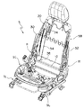
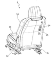
図1及び図2は、本発明にかかるリクライニング装置Rを備えた車両用シートSを示しており、左右一対のシートスライド装置SLを介して車体フロアに取り付けられるシートクッションSCと、シートクッションSCの後端部に傾倒自在に取り付けられたシートバックSBとを備えている。本発明にかかるリクライニング装置Rは、車両用シートSの両側におけるシートクッションSCとシートバックSBとの連結部に取り付けられ、シートクッションSCに対するシートバックSBの傾斜角を適宜調節するために使用される。
Hereinafter, embodiments of the present invention will be described with reference to the drawings.
1 and 2 show a vehicle seat S provided with a reclining device R according to the present invention. A seat cushion SC attached to a vehicle body floor via a pair of left and right seat slide devices SL, and a seat cushion SC And a seat back SB attached to the rear end portion so as to be tiltable. The reclining device R according to the present invention is attached to a connecting portion between the seat cushion SC and the seat back SB on both sides of the vehicle seat S, and is used to appropriately adjust the inclination angle of the seat back SB with respect to the seat cushion SC. .
本発明が適用される従来公知のリクライニング装置Rの全体構成を図3乃至図5を参照してまず説明する。 The overall configuration of a conventionally known reclining device R to which the present invention is applied will be described first with reference to FIGS.
図3乃至図5に示されるように、各リクライニング装置Rは、シートクッションSCに固定される第1ブラケット(第1の取付部材)2と、シートバックSBに第1ブラケット2に対向して固定される第2ブラケット(第2の取付部材)3と、第1及び第2ブラケット2,3間に介設される一対のロックプレート4と、一対のロックプレート4を離接する方向に移動させる駆動部材としてのカム5と、カム5を軸心回りに正逆回動操作する操作レバー(第1の操作手段)7と、この操作レバー7を抜け止めして保持する保持プレート8とを備えている。
As shown in FIGS. 3 to 5, each reclining device R is fixed to the first bracket (first mounting member) 2 fixed to the seat cushion SC and to the seat back SB so as to face the
第1ブラケット2は上部が円形に形成され、操作レバー7の一部を突設させたカム5との嵌合部7aが嵌入する嵌入孔21が上記上部円形の中心部分に穿設されるとともに、左方の面(図5における左方、すなわち第2ブラケット3との対向面)には、前後方向一対のガイド部材22が幅方向の内方(図5の左方)に向けて膨設されている。各ガイド部材22は、嵌入孔21を中心とした円弧状に形成され、嵌入孔21に対して点対称に形状設定されている。
The upper part of the
前後一対のガイド部材22間にはロックプレート4及びカム5が収容されるとともに、各ガイド部材22の上下端にはガイド突起22aが形成されており、ガイド突起22aの対向面間に各ロックプレート4の一部(後述する噛合部41)を摺接状態で嵌装する上下一対の案内溝が形成されている。
The lock plate 4 and the
第2ブラケット3は、下部が円形に形成されるとともに上部には取付部が形成されている。第2ブラケット3の左側面には、下部円形部を中心とした円形膨出部31が形成されるとともに、この円形膨出部31の中心部には第1ブラケット2の嵌入孔21に対向した貫通孔31aが穿設されている。
The second bracket 3 has a circular lower part and an attachment part on the upper part. On the left side surface of the second bracket 3, a circular
また、円形膨出部31の右側は装着凹部33となっており、その内半径は、上述した一対のガイド部材22の外周面の曲率半径より僅かに大きく設定され、第1ブラケット2と第2ブラケット3とを合わせた状態で、各ガイド部材22は、その外周面が装着凹部33の内周面に摺接しながら装着凹部33に嵌め込まれるようになっている。さらに、装着凹部33の内周面(側壁)の上下には、内歯34が対向して形成されている。
The right side of the circular bulging
第2ブラケット3の上縁部には、前後端部にそれぞれ取付け孔が穿設され、これらの取付け孔を介して第1ブラケット2が第2ブラケット3から外れないように押さえる押え板としての第3ブラケット35がボルト止めされ、第3ブラケット35がシートバックSBに固定される。そして、第2ブラケット3に第1ブラケット2を積層した状態で、第3ブラケット35を第2ブラケット3に固定することにより、第3ブラケット35が第1ブラケット2の回動を許容しながらその上部を押さえた状態になり、これによって第1ブラケット2の上部が第2ブラケット3から離反するのを防止している。
The upper edge of the second bracket 3 is provided with attachment holes at the front and rear ends, respectively, and a first presser plate as a presser plate that holds the
また、上記第1ブラケット2の下縁部にも前後端部にそれぞれ取付け孔が穿設され、これらの取付け孔を介してボルト止めされることにより第1ブラケット2がシートクッションSCに固定される。
Also, mounting holes are formed in the lower edge portion of the
各ロックプレート4は、第1ブラケット2の案内溝に上下動自在に嵌め込まれる噛合部41と、この噛合部41の両側に一体的に形成された第1肩部42及び第2肩部43と、第2肩部43から反対側に位置するロックプレート4の第1肩部42に向かって延びる脚部44とを備えている。噛合部41の先端縁には第2ブラケット3の内歯34と噛み合う係止歯41aが形成されており、ガイド部材22が装着凹部33に嵌め込まれた状態で係止歯41aが内歯34と噛み合うことにより第1ブラケット2と第2ブラケット3との相対回動が阻止される。一方、脚部44は、直線状外縁部がガイド部材22の直線状内縁部に摺接するとともに、直線状内縁部が一対のロックプレート4に囲繞された空間に回動自在に収容されたカム5の外周面に摺接するように形状設定されている。
Each lock plate 4 includes a meshing portion 41 that is fitted in the guide groove of the
脚部44の長さ寸法は、各ロックプレート4が、径方向外方に移動して係止歯41aが第2ブラケット3の内歯34と噛み合う噛合位置(ロック位置)と、径方向内方に移動して係止歯41aと第2ブラケット3の内歯34との噛み合いが解除される噛合解除位置(ロック解除位置)との間を移動できるように設定されている。さらに詳述すると、噛合位置と噛合解除位置との距離は、係止歯41aの歯丈寸法より若干大きめに設定され、ロックプレート4が嵌入孔21から径方向外方に向けて移動することによって噛合部41の係止歯41aが内歯34に噛み合う一方、ロックプレート4が嵌入孔21の方向に向けて移動することにより、係止歯41aの内歯34に対する噛み合いが解除される。
The length dimension of the leg portion 44 is such that each lock plate 4 moves radially outward and the engagement tooth 41a meshes with the
カム5は、略六角形状に形成されており、一方のロックプレート4と対向する三つの角部のうちの二つは、噛合位置ではロックプレート4の内周面と当接し、噛合解除位置では、残りの一つの角部が脚部44に形成された凸部(図示せず)と当接する。また、他方のロックプレート4と対向する三つの角部についても同様である。
The
また、カム5の中心部には長孔5aが穿設されており、図4に示されるように、長孔5aには左右のリクライニング装置Rを連結する連結軸10の一端が挿入され、操作レバー7の嵌合部7aを第1ブラケット2の嵌入孔21に嵌入させた後、嵌合部7aに穿設された長孔7bにさらに連結軸10の一端が挿入されることにより、カム5は操作レバー7により操作される。
A long hole 5a is formed in the center of the
操作レバー7を保持する保持プレート8は、操作レバー7の第1ブラケット2への装着状態を安定させるように第1ブラケット2に取り付けられている。保持プレート8は、図5に示されるように、操作レバー7を押さえるプレート本体81と、プレート本体81の上縁部に外方に向かって突設された円弧板82と、プレート本体81の下縁部後端に突設されたばね係止片83とを備えている。
The holding
また、操作レバー7の中間部にもばね係止片71が突設されており、操作レバー7のばね係止片71と保持プレート8のばね係止片83とにコイルばね84が張設されることによって操作レバー7は矢印A方向に付勢されている。
Further, a
また、第3ブラケット35にも、図5における右方に向かって突設されたばね係止片35aが突設され、このばね係止片35aと保持プレート8の円弧板82前縁部との間に渦巻きばね9が装着されている。そして、この渦巻きばね9によって第2ブラケット3が第3ブラケット35を介して矢印B方向に向かう付勢力を受け、シートバックSBは第2ブラケット3を介して常に前倒姿勢になるように付勢されている。
Further, the
上記構成の本発明にかかるリクライニング装置の作用を以下説明する。
操作レバー7を操作しない通常の着座状態では、コイルばね84の弾性力により操作レバー7は矢印A方向に付勢されていることから、操作レバー7に連結軸10を介して連結されたカム5も同様に矢印A方向に付勢されている。
The operation of the reclining device according to the present invention having the above configuration will be described below.
In a normal seating state in which the
この状態では、カム5の二つの角部が一方のロックプレート4の内周面とそれぞれ当接するとともに、当該二つの角部の反対側に位置する二つの角部が他方のロックプレート4の内周面とそれぞれ当接することで、ロックプレート4を径方向外方に付勢している。したがって、ロックプレート4の係止歯41aは、一対のガイド部材22の対向するガイド突起22aの間に形成された案内溝から外方に突出して、対向する第2ブラケット3の内歯34と噛み合っており、第2ブラケット3の第1ブラケット2に対する位置あるいはシートバックSBのシートクッションSCに対する傾斜角は所定の位置あるいは所定の角度に保持されている。
In this state, the two corners of the
この状態で、コイルばね84の弾性力に抗して操作レバー7のグリップ部を引き上げると、カム5は矢印Aの逆方向に回転し、カム5の一つの角部とその反対側に位置する角部が一対のロックプレート4の脚部44の凸部(図示せず)と当接して押圧することから、ロックプレート4の噛合部41は案内溝に沿って径方向内方に向かって摺動し、係止歯41aと第2ブラケット3の内歯34との噛み合いが解除され、ロックプレート4は噛合位置から噛合解除位置まで移動する。したがって、シートバックSBのシートクッションSCに対する傾倒姿勢(傾斜角度)を任意に設定し得るようになる。
In this state, when the grip portion of the
シートバックSBのシートクッションSCに対する傾倒姿勢を設定後、操作レバー7のグリップ部より手を離すと、コイルばね84の弾性力によりカム5は矢印A方向に回転して、ロックプレート4が径方向外方に摺動し、係止歯41aが第2ブラケット3の内歯34と再び噛み合い、シートバックSBは新たに設定された傾倒姿勢に保持される。
After setting the tilting posture of the seat back SB relative to the seat cushion SC, when the hand is released from the grip portion of the
以上、本発明が適用される従来公知のリクライニング装置Rの構成及び作用を説明したが、本発明の要旨につき以下説明する。 The configuration and operation of a conventionally known reclining device R to which the present invention is applied have been described above. The gist of the present invention will be described below.
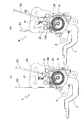
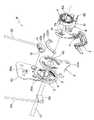
図6は本発明にかかるリクライニング装置Rを示しており、このリクライニング装置Rに設けられた第1ブラケット2の円形部の上部の一部には複数の係止歯23が形成されている。また、第2ブラケット3が取り付けられる第3ブラケット35には、係止歯23と嵌脱自在の係止爪12aを有する係止部材12がピン14を介して回動自在に取り付けられており、係止部材12の上部には、ばね係止片12bとワイヤ係止片12cとが係止部材12の一部を折曲することにより一体的に形成されている。
FIG. 6 shows a reclining device R according to the present invention, and a plurality of locking
さらに、ばね係止片12bに一端が係止されたコイルばね16の他端が、第3ブラケット35の一部を切り起こして形成したばね係止片35bに係止されており、コイルばね16の弾性力により係止部材12の係止爪12aは第1ブラケット2の係止歯23との噛み合いが解除される矢印Cの方向に常時付勢されている。
Further, the other end of the
なお、係止部材12の係止爪12aと第1ブラケット2の係止歯23は、所謂ラチェット機構を構成するように形状設定がなされており、ロックプレート4の係止歯41aと第2ブラケット3の内歯34との噛み合いが解除された状態で、係止部材12の係止爪12aと第1ブラケット2の係止歯23が噛み合うと、図6の矢印Dで示される第2ブラケット3の第1ブラケット2に対する回転は許容される一方、矢印Dの逆方向への第2ブラケット3の回転は阻止される。すなわち、シートバックSBの前倒は許容されるが、後倒は阻止される構成である。
The locking claws 12a of the locking
また、図1、図2及び図7に示されるように、シートバックフレームには取付部材18を介して操作レバー(第2の操作手段)20の一端が枢着されており、操作レバー20の他端はシートバックSBより後方に突出し、この突出部に操作ノブ25が取り付けられている。この操作レバー20はシートバックSBの背面側で上下方向に揺動操作されることから、シートバックSBの背面には操作レバー20が揺動するためのスリット24が上下方向に形成されている。
As shown in FIGS. 1, 2, and 7, one end of an operation lever (second operation means) 20 is pivotally attached to the seat back frame via an
操作レバー20の中間部には第1の連結部材としてのワイヤ26の一端が係止され、ワイヤ26の他端は円筒状分岐部材28に係止されている。分岐部材28には第2の連結部材としての3本のワイヤ30,32,34の一端が係止され、これら3本のワイヤ30,32,34のうち、2本のワイヤ30,32の他端は左右のリクライニング装置Rに設けられた係止部材12のワイヤ係止片12cに係止される一方、残りの1本のワイヤ34の他端は、左右のリクライニング装置Rを連結する連結軸10に一端が接合されたアーム36の他端に係止されている。
One end of a
上記構成の本発明にかかるリクライニング装置Rの上述した作用以外の作用を図8及び図9を参照して以下説明する。 Operations other than the above-described operation of the reclining device R according to the present invention having the above-described configuration will be described below with reference to FIGS.
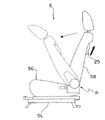
操作ノブ25を操作しない状態では、ロックプレート4の係止歯41aが第2ブラケット3の内歯34と噛み合って、図9の実線で示されるように、シートバックSBを所定の傾斜角に保持している。この時、図8(a)に示されるように、係止部材12の係止爪12aと第1ブラケット2の係止歯23との噛み合いは、コイルばね16の弾性力により解除されている。
When the
ここで、操作ノブ25を図9の矢印で示される方向に操作する(押し上げる)と、操作レバー20が上方に揺動してワイヤ26が上方に引っ張られるとともに、このワイヤ26に連結された3本のワイヤ30,32,34が上方に引っ張られる。その結果、連結軸10に固定されたアーム36が矢印E(図6参照)の方向に揺動して、連結軸10とともにカム5が回転するので、ロックプレート4の係止歯41aと第2ブラケット3の内歯34との噛み合いが解除される一方、左右のリクライニング装置Rの係止部材12がコイルばね16の弾性力に抗して矢印Cの逆方向に回転して、その係止爪12aが第1ブラケット2の係止歯23と噛み合う。なお、ワイヤ30,32,34の各々は、アウターケーブルとアウターケーブル内に摺動自在に設けられたインナーケーブルとにより構成されており、アウターケーブルを固定し、インナーケーブルを係止部材12のワイヤ係止片12cあるいは連結軸10に固定されたアーム36に係止することで、上述した動作を行う。
When the
上述したように、係止部材12の係止爪12aと第1ブラケット2の係止歯23はラチェット機構を構成して、シートバックSBの前倒のみ許容しているので、図9の破線で示されるようにシートバックSBは速やかに前倒するが、その後倒は阻止されている。
As described above, the latching claw 12a of the latching
また、操作ノブ25より手を離すと、操作レバー20が下方に揺動してワイヤ26,30,32,34が下方に引っ張られ、ロックプレート4の係止歯41aが第2ブラケット3の内歯34と再び噛み合うので、シートバックSBを任意の傾斜角に保持することができる。この時、左右のリクライニング装置Rの係止部材12の係止爪12aと第1ブラケット2の係止歯23との噛み合いは解除されている。
Further, when the hand is released from the
なお、上記実施の形態において、第1ブラケット2の外周面に係止歯23を形成するようにしたが、図10に示されるように、係止歯23aが形成された被係止部材23Aを第1ブラケット2とは別体で形成し、この被係止部材23Aを第1ブラケット2の所定の位置に接合するようにしてもよい。この場合、被係止部材23Aを除くリクライニング装置Rとして、図3乃至図5を参照して説明した従来公知のリクライニング装置Rを採用することができる。
In the above embodiment, the locking
また、上記実施の形態は、第1及び第2ブラケット2,3の間に一対のロックプレート4を介装するとともに、第2ブラケット3の両側に内歯34を形成して一対のロックプレート4と噛み合わせる構成としたが、本発明は必ずしもこの構成に限定されるわけではなく、シートクッションSCに固定される第1の取付部材とシートバックSBに固定される第2の取付部材を有し、第1及び第2の取付部材の間に係止歯を有する少なくとも一つのロック部材を介装し、このロック部材を第1及び第2の取付部材のいずれか一方に形成された係止歯にカム等の駆動部材を操作して噛み合わせるようにした構成のリクライニング装置にも適用可能である。
In the above embodiment, a pair of lock plates 4 are interposed between the first and
本発明にかかるリクライニング装置は、例えば車両用シートのうち最後列のシート以外の全てのシートに採用できるが、シートの後方から操作レバーを操作するだけの簡単な操作でシートバックの後倒を阻止する一方、シートバックを容易に前倒できる構成にしたので、安全性が高く、特に運転者用のシート(運転席)に採用すると効果的である。 The reclining device according to the present invention can be applied to, for example, all the seats in the vehicle except the last row. On the other hand, since the seat back can be easily moved forward, the safety is high, and it is particularly effective when used in a driver's seat (driver's seat).
2 第1ブラケット、 3 第2ブラケット、 4 ロックプレート、 5 カム、
5a 長孔、 7 操作レバー、 7a 嵌合部、 7b 長孔、
8 保持プレート、 9 渦巻きばね、 10 連結軸、 12 係止部材、
12a 係止爪、 16 コイルばね、 18 取付部材、 20 操作レバー、
21 嵌入孔、 22 ガイド部材、 22a ガイド突起、 23 係止歯、
23A 被係止部材、 23a 係止歯、 24 スリット、 25 操作ノブ、
26,30,32,34 ワイヤ、 28 分岐部材、 31 円形膨出部、
31a 貫通孔、 33 装着凹部、 34 内歯、 35 第3ブラケット、
36 アーム、 41 噛合部、 41a 係止歯、 42 第1肩部、
43 第2肩部、 44 脚部、 84 コイルばね、 R リクライニング装置、
S シート、 SB シートバック、 SC シートクッション、
SL シートスライド装置。
2 First bracket, 3 Second bracket, 4 Lock plate, 5 Cam,
5a long hole, 7 operation lever, 7a fitting part, 7b long hole,
8 holding plate, 9 spiral spring, 10 connecting shaft, 12 locking member,
12a locking claw, 16 coil spring, 18 mounting member, 20 operation lever,
21 insertion hole, 22 guide member, 22a guide projection, 23 locking teeth,
23A Locked member, 23a Locking tooth, 24 Slit, 25 Operation knob,
26, 30, 32, 34 wire, 28 branch member, 31 circular bulge,
31a through-hole, 33 mounting recess, 34 internal teeth, 35 third bracket,
36 arms, 41 meshing portions, 41a locking teeth, 42 first shoulder,
43 second shoulder, 44 leg, 84 coil spring, R reclining device,
S seat, SB seat back, SC seat cushion,
SL sheet slide device.
Claims (6)
シートクッションに対しシートバックを所定の傾斜角に保持するためのロック部材と、該ロック部材を操作するための第1の操作手段と、シートバックの後倒を阻止する一方、シートバックの前倒を許容するラチェット機構と、該ラチェット機構と前記ロック部材を操作するための第2の操作手段を備え、前記第1の操作手段で前記ロック部材を操作することにより、シートクッションに対しシートバックが所定の傾斜角に保持されるロック位置からシートクッションに対しシートバックの傾倒が許容されるロック解除位置まで前記ロック部材を駆動する一方、前記第2の操作手段で前記ロック部材及び前記ラチェット機構を操作することにより、前記ロック部材を前記ロック位置から前記ロック解除位置まで駆動すると同時に、シートバックの後倒を阻止し、さらにシートバックの前倒を許容して任意の位置でシートバックをロックできるようにしたことを特徴とするシートのリクライニング装置。 A seat reclining device for appropriately adjusting the inclination angle of a seat back attached to a seat cushion so as to freely tilt,
A lock member for holding the seat back at a predetermined inclination angle with respect to the seat cushion, a first operating means for operating the lock member, and preventing the seat back from being moved backward, while the seat back being moved forward And a second operating means for operating the ratchet mechanism and the locking member. By operating the locking member by the first operating means, the seat back is moved against the seat cushion. The lock member and the ratchet mechanism are driven by the second operating means while the lock member is driven from a lock position held at a predetermined inclination angle to a lock release position where the seat back is allowed to tilt with respect to the seat cushion. By operating, the locking member is driven from the locked position to the unlocked position, and at the same time, the seat back Sheet reclining device to prevent losses, further to permit forward tilting of the seat back, characterized in that to be able to lock the seat back in any position after.
Priority Applications (1)
| Application Number | Priority Date | Filing Date | Title |
|---|---|---|---|
| JP2006043523A JP4795809B2 (en) | 2006-02-21 | 2006-02-21 | Seat reclining device |
Applications Claiming Priority (1)
| Application Number | Priority Date | Filing Date | Title |
|---|---|---|---|
| JP2006043523A JP4795809B2 (en) | 2006-02-21 | 2006-02-21 | Seat reclining device |
Publications (2)
| Publication Number | Publication Date |
|---|---|
| JP2007222206A JP2007222206A (en) | 2007-09-06 |
| JP4795809B2 true JP4795809B2 (en) | 2011-10-19 |
Family
ID=38544576
Family Applications (1)
| Application Number | Title | Priority Date | Filing Date |
|---|---|---|---|
| JP2006043523A Expired - Fee Related JP4795809B2 (en) | 2006-02-21 | 2006-02-21 | Seat reclining device |
Country Status (1)
| Country | Link |
|---|---|
| JP (1) | JP4795809B2 (en) |
Family Cites Families (2)
| Publication number | Priority date | Publication date | Assignee | Title |
|---|---|---|---|---|
| JPS57117232U (en) * | 1981-01-14 | 1982-07-20 | ||
| JPH03104562A (en) * | 1989-09-14 | 1991-05-01 | Noritake Co Ltd | Regenerating method of grinding belt |
-
2006
- 2006-02-21 JP JP2006043523A patent/JP4795809B2/en not_active Expired - Fee Related
Also Published As
| Publication number | Publication date |
|---|---|
| JP2007222206A (en) | 2007-09-06 |
Similar Documents
| Publication | Publication Date | Title |
|---|---|---|
| JP2009292435A (en) | Seat | |
| JP5109543B2 (en) | Vehicle seat | |
| JP2007118827A (en) | Seat device for vehicle | |
| JP5710831B1 (en) | Headrest tilting device and headrest | |
| JP2009039340A (en) | Reclining device | |
| JP6809161B2 (en) | Vehicle seat | |
| JP5505317B2 (en) | Vehicle seat device | |
| JP6311545B2 (en) | Rotating tilt sheet | |
| JP4795809B2 (en) | Seat reclining device | |
| JP2006315623A (en) | Vehicle seat | |
| KR101853739B1 (en) | Recliner device for vehicle having work in funtion | |
| KR100559464B1 (en) | Reclining device of seat for vehicle | |
| WO2019093250A1 (en) | Slide device for vehicle seat | |
| JP6772902B2 (en) | Vehicle seat | |
| JP5630811B2 (en) | Vehicle seat device | |
| JP6580693B2 (en) | Seat back advancer and vehicle seat | |
| JP2019085013A (en) | Reclining lock release device of vehicle seat | |
| JP5691774B2 (en) | Vehicle seat | |
| JP5344387B2 (en) | Sheet | |
| US20230249586A1 (en) | Seat assembly with override condition | |
| JP4158643B2 (en) | Vehicle seat device | |
| JP2006325918A (en) | Sheet reclining system | |
| KR101850730B1 (en) | headrest for vehicle | |
| KR101869052B1 (en) | Seat Having variable Shaft for Vehicle | |
| JP2018079861A (en) | Vehicle seat |
Legal Events
| Date | Code | Title | Description |
|---|---|---|---|
| RD03 | Notification of appointment of power of attorney |
Free format text: JAPANESE INTERMEDIATE CODE: A7423 Effective date: 20080131 |
|
| A621 | Written request for application examination |
Free format text: JAPANESE INTERMEDIATE CODE: A621 Effective date: 20090114 |
|
| A977 | Report on retrieval |
Free format text: JAPANESE INTERMEDIATE CODE: A971007 Effective date: 20110708 |
|
| TRDD | Decision of grant or rejection written | ||
| A01 | Written decision to grant a patent or to grant a registration (utility model) |
Free format text: JAPANESE INTERMEDIATE CODE: A01 Effective date: 20110719 |
|
| A01 | Written decision to grant a patent or to grant a registration (utility model) |
Free format text: JAPANESE INTERMEDIATE CODE: A01 |
|
| A61 | First payment of annual fees (during grant procedure) |
Free format text: JAPANESE INTERMEDIATE CODE: A61 Effective date: 20110728 |
|
| R150 | Certificate of patent or registration of utility model |
Ref document number: 4795809 Country of ref document: JP Free format text: JAPANESE INTERMEDIATE CODE: R150 Free format text: JAPANESE INTERMEDIATE CODE: R150 |
|
| FPAY | Renewal fee payment (event date is renewal date of database) |
Free format text: PAYMENT UNTIL: 20140805 Year of fee payment: 3 |
|
| R250 | Receipt of annual fees |
Free format text: JAPANESE INTERMEDIATE CODE: R250 |
|
| R250 | Receipt of annual fees |
Free format text: JAPANESE INTERMEDIATE CODE: R250 |
|
| R250 | Receipt of annual fees |
Free format text: JAPANESE INTERMEDIATE CODE: R250 |
|
| R250 | Receipt of annual fees |
Free format text: JAPANESE INTERMEDIATE CODE: R250 |
|
| R250 | Receipt of annual fees |
Free format text: JAPANESE INTERMEDIATE CODE: R250 |
|
| R250 | Receipt of annual fees |
Free format text: JAPANESE INTERMEDIATE CODE: R250 |
|
| LAPS | Cancellation because of no payment of annual fees |