JP4793288B2 - Light guide and bifurcated linear light source device - Google Patents
Light guide and bifurcated linear light source device Download PDFInfo
- Publication number
- JP4793288B2 JP4793288B2 JP2007051039A JP2007051039A JP4793288B2 JP 4793288 B2 JP4793288 B2 JP 4793288B2 JP 2007051039 A JP2007051039 A JP 2007051039A JP 2007051039 A JP2007051039 A JP 2007051039A JP 4793288 B2 JP4793288 B2 JP 4793288B2
- Authority
- JP
- Japan
- Prior art keywords
- light
- light guide
- guide
- emitted
- light source
- Prior art date
- Legal status (The legal status is an assumption and is not a legal conclusion. Google has not performed a legal analysis and makes no representation as to the accuracy of the status listed.)
- Active
Links
Images


Classifications
-
- G—PHYSICS
- G02—OPTICS
- G02B—OPTICAL ELEMENTS, SYSTEMS OR APPARATUS
- G02B6/00—Light guides; Structural details of arrangements comprising light guides and other optical elements, e.g. couplings
- G02B6/0001—Light guides; Structural details of arrangements comprising light guides and other optical elements, e.g. couplings specially adapted for lighting devices or systems
- G02B6/0005—Light guides; Structural details of arrangements comprising light guides and other optical elements, e.g. couplings specially adapted for lighting devices or systems the light guides being of the fibre type
- G02B6/001—Light guides; Structural details of arrangements comprising light guides and other optical elements, e.g. couplings specially adapted for lighting devices or systems the light guides being of the fibre type the light being emitted along at least a portion of the lateral surface of the fibre
-
- B—PERFORMING OPERATIONS; TRANSPORTING
- B41—PRINTING; LINING MACHINES; TYPEWRITERS; STAMPS
- B41J—TYPEWRITERS; SELECTIVE PRINTING MECHANISMS, i.e. MECHANISMS PRINTING OTHERWISE THAN FROM A FORME; CORRECTION OF TYPOGRAPHICAL ERRORS
- B41J2/00—Typewriters or selective printing mechanisms characterised by the printing or marking process for which they are designed
- B41J2/435—Typewriters or selective printing mechanisms characterised by the printing or marking process for which they are designed characterised by selective application of radiation to a printing material or impression-transfer material
- B41J2/447—Typewriters or selective printing mechanisms characterised by the printing or marking process for which they are designed characterised by selective application of radiation to a printing material or impression-transfer material using arrays of radiation sources
- B41J2/45—Typewriters or selective printing mechanisms characterised by the printing or marking process for which they are designed characterised by selective application of radiation to a printing material or impression-transfer material using arrays of radiation sources using light-emitting diode [LED] or laser arrays
-
- H—ELECTRICITY
- H04—ELECTRIC COMMUNICATION TECHNIQUE
- H04N—PICTORIAL COMMUNICATION, e.g. TELEVISION
- H04N1/00—Scanning, transmission or reproduction of documents or the like, e.g. facsimile transmission; Details thereof
- H04N1/024—Details of scanning heads ; Means for illuminating the original
- H04N1/028—Details of scanning heads ; Means for illuminating the original for picture information pick-up
- H04N1/02815—Means for illuminating the original, not specific to a particular type of pick-up head
- H04N1/0282—Using a single or a few point light sources, e.g. a laser diode
- H04N1/02835—Using a single or a few point light sources, e.g. a laser diode in combination with a light guide, e.g. optical fibre, glass plate
-
- G—PHYSICS
- G02—OPTICS
- G02B—OPTICAL ELEMENTS, SYSTEMS OR APPARATUS
- G02B6/00—Light guides; Structural details of arrangements comprising light guides and other optical elements, e.g. couplings
- G02B2006/0098—Light guides; Structural details of arrangements comprising light guides and other optical elements, e.g. couplings for scanning
Description
本発明は、導光体及び2分岐線状光源装置に係わり、特に、ファクシミリ、複写機、イメージスキャナー、バーコードリーダ等に使用される画像読取装置の照明用光源として利用される導光体及び2分岐線状光源装置に関する。 The present invention relates to a light guide and a two-branch linear light source device, and in particular, a light guide used as an illumination light source for an image reading device used in a facsimile, a copying machine, an image scanner, a barcode reader, and the like. The present invention relates to a two-branch linear light source device.
近年、パーソナルファクシミリ等の画像読取装置において、発光ダイオード(以下、LEDと言う)の出力向上と受光素子としてのCCD型センサの高感度化により、小型で低消費電力のLEDが読取光源装置の光源として使用されるようになってきている。このようなLEDを光源として備えた従来の線状光源装置は、光源の個数を低減させ、かつ均一な照明強度を得ることを目的として、導光体を用い、光源から放射された光を導光体に入射させて所望の方向に光を導光させるものが知られている。 In recent years, in an image reading apparatus such as a personal facsimile, a small and low power consumption LED is used as a light source of a reading light source device due to an improvement in output of a light emitting diode (hereinafter referred to as an LED) and high sensitivity of a CCD sensor as a light receiving element Has come to be used as. A conventional linear light source device having such an LED as a light source uses a light guide to guide the light emitted from the light source in order to reduce the number of light sources and obtain uniform illumination intensity. There is known one that enters a light body and guides light in a desired direction.
特許文献1には、導光体の短手方向の断面形状において、光出射面に対向する位置に、逆V字型の光変向面が形成された導光体が記載されている。光出射面は他の部分より曲率が小さく形成されているので、光出射面から出射した光は集光されて、例えば、原稿面に対して指向性を有する光が照射されることが記載されている。
また、特許文献2には、導光体の短手方向の断面形状において、光出射面が円弧又は楕円の弧などの形状からなるレンズ面状に形成され、光出射面に対向する位置に光変向面を2つ設けた導光体が記載されている。
また、特許文献3には、 導光体の一端面に光源が取り付けられた照明ユニットが対向するように2組配置された光源装置が記載されている。導光体はアクリルやポリカーボネートなどの光透過性の高い樹脂又は光透過性の高い光学ガラスで構成され、一側面に光出射面が形成されている。光源は、例えば、面実装型のLEDが1個又は複数個取り付けられており、LEDから導光体の一端面に入射した光は導光体の内面で反射しながら長手方向へ導かれるとともに、光出射面から矢印方向に光を出射するように構成されている。各照明ユニットは、それらの光出射面から出射した光が原稿面の原稿読取面を照射するように配置され、各々が同一領域である原稿読取面を照射することが記載されている。
Further, in
しかしながら、特許文献1や特許文献2に記載された導光体は、1方向から原稿読取面に光を照射するので、被照射物である紙面に折り目や貼り合わせによる段差部分があると、影が生じる。また、特許文献3に記載された光源装置では、2方向から原稿読取面に光を照射するように構成されているので、紙面に折り目や貼り合わせによる段差部分があっても、影を生じないが、導光体を2つ配置する必要があるので、装置全体が大きくなり、小型化の要請に応えることができない。
本発明の目的は、上記の問題点に鑑み、2方向から原稿読取面に光を照射することができると共に、装置の小型化を実現することのできる導光体及び2分岐線状光源装置を提供することにある。
However, since the light guides described in
In view of the above problems, an object of the present invention is to provide a light guide and a two-branch linear light source device that can irradiate light on a document reading surface from two directions and can reduce the size of the device. It is to provide.
本発明は、上記の課題を解決するために、次のような手段を採用した。
第1の手段は、LED光源と、該LED光源からの光を導く導光体と、反射鏡とから構成され、前記導光体から出射された光を原稿読取面に照射する原稿読取装置であって、前記導光体は、長手方向に伸びる光変向面と、該光変向面に対向する光出射面とが形成された透明な棒状の導光体であり、前記光変向面は、該光変向面に対する長手方向に伸びる垂直面が交差するように配置された2つの面で形成され、前記光出射面は2つの前記光変向面にそれぞれ対向するように設けられた2つの面で形成されており、前記LED光源は、前記導光体の長手方向両端の少なくとも一方に設けられた光入射部に対向して設けられており、前記導光体から出射された光を前記原稿面に向けて反射する前記反射鏡が設けられており、前記LED光源から前記導光体に入射した光は、前記光変向面で変向され、前記導光体の一方の光出射面から出射される光は前記原稿読取面に向けて出射され、また前記導光体の他方の光出射面から出射される光は前記反射鏡に向けて出射されることを特徴とする原稿読取装置である。
第2の手段は、第1の手段において、前記導光体の各光変向面は、導光体の短手方向に対して凹面状に形成されていることを特徴とする原稿読取装置である。
第3の手段は、第1の手段において、前記導光体の前記光出射面は、曲率が等しい又は異なる2つの曲面で形成されていることを特徴とする原稿読取装置である。
第4の手段は、線状光源装置が、LED光源と、該LED光源からの光を導く導光体と、反射鏡とから構成され、前記LED光源から前記導光体に入射した光は光変向面で変向され、前記導光体の一方の光出射面から出射された光は原稿読取面に向けて出射され、前記導光体の他方の光出射面から出射された光は前記反射鏡によって前記原稿読取面に向けて反射される原稿読取装置に用いられる線状光源装置であって、前記LED光源は、前記導光体の長手方向両端の少なくとも一方に設けられた光入射部に対向して設けられており、
前記導光体は、長手方向に伸びる前記光変向面と、該光変向面に対向する前記光出射面とが形成された透明な棒状の導光体であり、前記光変向面は該光変向面に対する長手方向に伸びる垂直面が交差するように配置された2つの面で形成され、前記光出射面は2つの前記光変向面にそれぞれ対向するように設けられた2つの面で形成されており、前記反射鏡は、前記導光体の他方の光出射面から出射された光を、導光体の一方の光出射面から出射された光が向かう原稿読取面に向けて反射することを特徴とする、原稿読取装置に用いられる線状光源装置である。
第5の手段は、第4の手段において、前記導光体の各光変向面は導光体の短手方向に対して凹面状に形成されていることを特徴とする線状光源装置である。
第6の手段は、第4の手段において、前記導光体の前記光出射面が曲率が等しい又は異なる2つの曲面で形成されていることを特徴とする線状光源装置である。
The present invention employs the following means in order to solve the above problems.
The first means is an original reading apparatus that includes an LED light source, a light guide that guides light from the LED light source, and a reflecting mirror, and irradiates the original reading surface with light emitted from the light guide. The light guide is a transparent rod-shaped light guide formed with a light turning surface extending in the longitudinal direction and a light emitting surface facing the light turning surface, and the light turning surface. Is formed of two surfaces arranged so that a vertical plane extending in the longitudinal direction with respect to the light redirecting surface intersects, and the light emitting surface is provided to face the two light redirecting surfaces, respectively. The light source is formed of two surfaces, and the LED light source is provided so as to be opposed to the light incident portions provided at at least one of the longitudinal ends of the light guide, and the light emitted from the light guide the and the reflecting mirror is provided for reflecting the document surface, before from the LED light source Light incident on the light guide is redirected by the light redirecting surface, light emitted from one light exit surface of the light guide is emitted toward the document reading surface, and the light guide The light emitted from the other light emitting surface is emitted toward the reflecting mirror.
A second means is an original reading apparatus according to the first means, wherein each light turning surface of the light guide is formed in a concave shape with respect to the short direction of the light guide. is there.
A third means is the original reading apparatus according to the first means, wherein the light emitting surface of the light guide is formed by two curved surfaces having the same or different curvature.
According to a fourth means, the linear light source device includes an LED light source, a light guide that guides light from the LED light source, and a reflecting mirror, and light incident on the light guide from the LED light source is light. is deflected by the diverting surface, light emitted from one of the light emitting surface of the light guide is emitted toward the scanning surface, light emitted from the other light emitting surface of the light guide body said A linear light source device used in a document reading device that is reflected by a reflecting mirror toward the document reading surface, wherein the LED light source is a light incident portion provided at at least one of the longitudinal ends of the light guide. It is provided opposite to
The light guide is a transparent rod-shaped light guide in which the light turning surface extending in the longitudinal direction and the light emitting surface facing the light turning surface are formed, and the light turning surface is The light diverting surface is formed by two surfaces arranged so as to intersect with each other in a longitudinal direction extending in the longitudinal direction, and the light emitting surface is provided so as to face the two light diverting surfaces, respectively. The reflecting mirror directs the light emitted from the other light exit surface of the light guide to the original reading surface to which the light emitted from the one light exit surface of the light guide travels. The linear light source device used in the document reading device is characterized in that the light source is reflected .
A fifth means is a linear light source device according to the fourth means, wherein each light diverting surface of the light guide is formed in a concave shape with respect to the lateral direction of the light guide. is there.
A sixth means is a linear light source device according to the fourth means, wherein the light emitting surface of the light guide is formed by two curved surfaces having the same curvature or different curvatures.
請求項1に記載の発明によれば、LED光源と、該LED光源からの光を導く導光体と、反射鏡とから構成され、前記導光体から出射された光を原稿読取面に照射する原稿読取装置であって、前記導光体は、長手方向に伸びる光変向面と、該光変向面に対向する光出射面とが形成された透明な棒状の導光体であり、前記光変向面は、該光変向面に対する長手方向に伸びる垂直面が交差するように配置された2つの面で形成され、前記光出射面は2つの前記光変向面にそれぞれ対向するように設けられた2つの面で形成されており、前記LED光源は、前記導光体の長手方向両端の少なくとも一方に設けられた光入射部に対向して設けられており、前記導光体から出射された光を前記原稿面に向けて反射する前記反射鏡が設けられており、前記LED光源から前記導光体に入射した光は、前記光変向面で変向され、前記導光体の一方の光出射面から出射される光は前記原稿読取面に向けて出射され、また前記導光体の他方の光出射面から出射される光は前記反射鏡に向けて出射されるようにしたので、2方向から原稿読取面への光を照射する構成が容易となり、また、1つの導光体しか用いないので装置の小型化を実現することができる。
請求項2に記載の発明によれば、導光体の各光変向面は、導光体の短手方向に対して凹面状に形成されているので、光変向面から変向される光を収束させて光出射面に入射させることができ、光出射面の形状の如何に関わらず光出射面から2方向に出射される光を各々収束して出射させることができる。
請求項3に記載の発明によれば、導光体の前記光出射面は、曲率が等しい又は異なる2つの曲面で形成されているので、光出射面から2方向に出射される光を各々任意の方向に収束し出射させることが容易となる。
請求項4に記載の発明によれば、線状光源装置が、LED光源と、該LED光源からの光を導く導光体と、反射鏡とから構成され、前記LED光源から前記導光体に入射した光は光変向面で変向され、前記導光体の一方の光出射面から出射された光は原稿読取面に向けて出射され、前記導光体の他方の光出射面から出射された光は前記反射鏡によって前記原稿読取面に向けて反射される原稿読取装置に用いられる線状光源装置であって、前記LED光源は、前記導光体の長手方向両端の少なくとも一方に設けられた光入射部に対向して設けられており、前記導光体は、長手方向に伸びる前記光変向面と、該光変向面に対向する前記光出射面とが形成された透明な棒状の導光体であり、前記光変向面は該光変向面に対する長手方向に伸びる垂直面が交差するように配置された2つの面で形成され、前記光出射面は2つの前記光変向面にそれぞれ対向するように設けられた2つの面で形成されており、前記反射鏡は、前記導光体の他方の光出射面から出射された光を、導光体の一方の光出射面から出射された光が向かう原稿読取面に向けて反射するように構成したので、2方向から原稿読取面への光を照射する構成が容易となり、また、1つの導光体しか用いないので装置の小型化を実現することができる。
請求項5に記載の発明によれば、導光体の各光変向面は、導光体の短手方向に対して凹面状に形成されているので、光変向面から変向される光を収束させて光出射面に入射させることができ、光出射面の形状の如何に関わらず光出射面から2方向に出射される光を各々収束して出射させることができる。
請求項6に記載の発明によれば、導光体の前記光出射面は、曲率が等しい又は異なる2つの曲面で形成されているので、光出射面から2方向に出射される光を各々任意の方向に収束し出射させることが容易となる。
According to the first aspect of the present invention, the document reading surface includes an LED light source, a light guide that guides light from the LED light source, and a reflecting mirror, and irradiates the document reading surface with light emitted from the light guide. The light guide is a transparent rod-shaped light guide formed with a light turning surface extending in the longitudinal direction and a light emitting surface facing the light turning surface. The light diverting surface is formed by two surfaces arranged so that a vertical plane extending in the longitudinal direction with respect to the light diverting surface intersects, and the light emitting surface faces the two light diverting surfaces, respectively. The LED light source is provided to face the light incident portion provided at at least one of the longitudinal ends of the light guide, and the light guide the reflector is provided for reflecting the original surface the light emitted from the Light incident on the light guide from the ED light source is redirected by the light redirecting surface, light emitted from one light exit surface of the light guide is emitted toward the document reading surface, and Since the light emitted from the other light emitting surface of the light guide is emitted toward the reflecting mirror, it is easy to irradiate light from two directions to the document reading surface. Since only one light guide is used, the apparatus can be downsized.
According to the second aspect of the present invention, each light diverting surface of the light guide is formed in a concave shape with respect to the short side direction of the light guide, and thus is deflected from the light diverting surface. The light can be converged and incident on the light exit surface, and the light emitted from the light exit surface in two directions can be converged and emitted regardless of the shape of the light exit surface.
According to the third aspect of the present invention, the light exit surface of the light guide is formed by two curved surfaces having the same curvature or different curvatures. Therefore, the light emitted from the light exit surface in two directions is arbitrary. It is easy to converge and emit in the direction.
According to invention of
According to the fifth aspect of the present invention, each light turning surface of the light guide is formed in a concave shape with respect to the short direction of the light guide, so that the light turning surface is turned from the light turning surface. The light can be converged and incident on the light exit surface, and the light emitted from the light exit surface in two directions can be converged and emitted regardless of the shape of the light exit surface.
According to the sixth aspect of the present invention, since the light exit surface of the light guide is formed by two curved surfaces having the same or different curvatures, the light emitted from the light exit surface in two directions is arbitrary. It is easy to converge and emit in the direction.
本発明の第1の実施形態を図1ないし図5を用いて説明する。
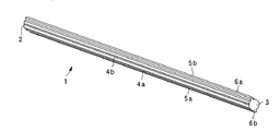
図1は、本実施形態の発明に係る導光体1の斜視図である。
同図において、1は導光体、2は導光体1の長手方向の一端面に形成された光入射面、3は導光体1の長手方向の他端面、4a、4bは光変向面(反射面)、5a、5bは光出射面、6a、6bは光変向面4a、4bと光出射面5a、5bとの間の側面に設けられた一対の突起部である。
導光体1は、棒状の透明なアクリル樹脂よりなり、半径がφ5〜6の細い棒状に形成され、長さが320mmであり、一対の突起部6a、6bは、導光体1の両端を保持しただけでは導光体1が撓み、照明位置がずれてしまうので、固定保持を容易にするために設けられる。導光体1は、少なくとも一方の長手方向端面に光入射面2が設けられ、長手方向に伸びる一方の側面に、第1の光変向面4a及び第2の光変向面4bが形成されており、第1の光変向面4a及び第2の光変向面4bは、第1の光変向面4a及び第2の光変向面4bに対する長手方向に伸びる垂直面が交差するように形成されている。また、導光体1の長手方向に伸びる他方の側面には、第1の光変向面4a及び第2の光変向面4bに対向して光出射面5a、5bが形成されている。光出射面5a、5bは、共通の面で形成され断面は略半円形である。
A first embodiment of the present invention will be described with reference to FIGS.
FIG. 1 is a perspective view of a
In the figure, 1 is a light guide, 2 is a light incident surface formed on one end surface of the
The
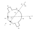
図2は、図1に示した第1の光変向面4a及び第2の光変向面4bを有する導光体1を、長手方向の一方の端面、即ち、光入射面2または長手方向の他端面3から見た投影図である。
この投影図において、第1の光変向面4a及び第2の光変向面4bは、線分4a、4bとして表されている。投影図において線分として表されている第1の光変向面4aに対して垂直で、かつ、第1の光変向面4aの中央から光変向面5aに向かって進む線を第1の垂直線15aとする。同様に、投影図において線分として表されている第2の光変向面4bに対して垂直で、かつ、第2の光変向面4bの中央から光変向面5bに向かって進む線を第2の垂直線15bとする。この2つの垂直線、第1の垂直線15aと第2の垂直線15bは、交差角度θ1をなして交差する。なお、第1の垂直線15aと第2の垂直線15bは、図1に示すような斜視図でみると、長手方向に伸びる面となっている。この第1の垂直線15aまたは第2の垂直線15bを含み、導光体1の長手方向に伸びる仮想平面を「光変向面に対する長手方向に伸びる垂直面」とよぶ。
2 shows the
In this projection view, the first light turning surface 4a and the second
第1の光変向面4aと第2の光変向面4bは、図3の第1の光変向面4aに示すように、長手方向に山型の凸凹溝が多数並列に形成されているので、第1の光変向面4a及び第2の光変向面4bは平面に形成することにより、導光体1を射出成形して製造する際に用いる金型等の加工が容易となる。また、第1の光変向面4aと第2の光変向面4bは、短手方向の長さが0.5mm〜2mm、例えば、1mm幅の平面状に形成され、交差角度θ1が45°〜65°、例えば、55°となるように互いに隔てて配置される。さらに、第1の光変向面4aと第2の光変向面4bは、第1の垂直線15aと第2の垂直線15bが導光体1の光出射面5a、5b側の半円形の曲率中心線で交差するように設けられると共に、前記半円形の半径より遠方に配置され、光出射面5a、5bからの出射光の収束性をよくしている。
As shown in the first light turning surface 4a of FIG. 3, the first light turning surface 4a and the second
第1の光変向面4a及び第2の光変向面4bには、長手方向に山型の凸凹溝が多数並列に形成されているので、光入射面2から入射した光は、導光体1の内部を全反射を繰り返しながら、導光体1の長手方向、即ち、他端面3方向に効率良く導光される。導光された長手方向の角度成分の光は、第1の光変向面4a及び第2の光変向面4bにより、各々に対向する光出射面5a及び光出射面5b方向(約90°方向)に向きを変えられ、光出射面5a及び光出射面5bからスネル則に従って出射する。
Since the first light diverting surface 4a and the second
図3は、図1に示した導光体1を、第1の光変向面4aの中心から長手方向に沿う垂直面で切断した断面図である。
同図において、7はLEDからなる光源である。光源7は導光体1の長手方向の一方の端部に形成された光入射部2に光を照射する方向に配置され、光源7と導光体1とは極めて近い距離で離間して設けられ、光源7から放射された光は大気中に放射され、その後、導光体1の内部に入射する。
光源7から導光体1に入射された光は、導光体1の内部を全反射し、長手方向Xに導光される。導光される過程で、光変向面4aの山型の凹凸溝の斜面に入射した光は、導光体1の短手(幅)方向Yに向きを変え、光出射面5aから出射される。光変向面4aの山型の凹凸溝の斜面は、光源7からの光A1を光出射面5aに対して概ね垂直方向に放射する光A2となるように、角度が調整されているので、光変向面4aの凹凸溝の斜面に入射した光A1は、光変向面4aから光出射面5aに向かう導光体1の幅方向Yに進む光A2となる。また、光源7から光出射面5aに入射した光B1は、光出射面5aで全反射し、入射角の角度を有したまま長手方向Xに進む光B2となる。その後、反射光B2は、光変向面4aの凹凸溝の斜面に入射し、光変向面4aから光出射面5aに向かう導光体1の短手(幅)方向Yに進む光B3となる。
FIG. 3 is a cross-sectional view of the
In the figure,
The light incident on the
図3に示すように、光変向面4aの山型の凹凸溝の頂点の間隔は、光源7に近い方では広く、遠い方では狭くなるように形成されている。即ち、光変向面4aの山型の凹凸溝の頂点の間隔は光源7から遠ざかるほど小さくなるように調整されている。このように構成することにより、光源7から入射された光の変向する確率を一定又は任意に調整することができ、所望の照度分布が得られる。また、光変向面4aが形成された部分の導光体1の外側面には、図示されていないがアルミニウムのフィルムが設けられている。アルミニウムのフィルムは反射膜として機能し、光変向面4aから導光体1の外部に光が出射しないようにし、被照明側へ効率良く照射させるとともに、迷光を防ぐことができる。
As shown in FIG. 3, the distance between the apexes of the ridge-shaped concave and convex grooves of the light turning surface 4a is formed so as to be wider near the
図4及び図5は、各々図1ないし図3に示した導光体1を適用した2分岐線状光源装置の一部を示す斜視図及び導光体1の短手方向に沿って切断した2分岐線状光源装置の断面図である。
これらの図において、8は原稿読取面9の中心に垂直な面に対して導光体1と略対称な位置に配置された反射鏡、9は原稿読取面、10はケース、11は導光体1を固定する略コ字状に形成された保持部、12は底面から伸び導光体1を固定する略コ字状に形成された支持部、13、14はケース10に設けられ光を通過する透明な窓である。なお、その他の構成は図3に示した同符号の構成に対応する。
4 and 5 are perspective views showing a part of a two-branch linear light source device to which the
In these drawings, 8 is a reflecting mirror disposed at a position substantially symmetrical to the
反射鏡8は、第1の光変向面4a及び第2の光変向面4bの長手方向の長さと同じ長さを有する樋状ミラーで構成され、例えば、光輝アルミ板または反射面にアルミ膜が形成されたものから構成され、その形状は、断面楕円状または断面放物線状に形成されている。このように構成することにより、導光体1の光出射面5bから出射した光の向きを変え、原稿読取面9に導くことができる。反射鏡8は、導光体1の第2の光出射面5bから出射した光のほぼ全てをとらえて、原稿読取面9に向けて反射させるために、ケース10の上面から底面にかかる程度の大きさを有している。また、反射光を遮らないように、ケース10の反射鏡8より導光体1側は窓14とすることが好ましい。また、導光体1と反射鏡8はケース10に固定されている。また、一対の突起部6a、6bが保持部11と支持部12の間に挟まれるようにして固定され、回転しないように保持される。導光体1をこのように固定保持することによって、接着剤を用いることなく、装置に容易に取り付けることができる。
The reflecting
導光体1と光源7は離間して設けられているので、導光体1に入射する光は、入射角度90°に近い場合であっても、導光体1の屈折率が約1.5であるため、入射後(導光体内部で)の角度は、導光体1の側面に対して臨界角度(42°)を越える。従って、導光体1の側面から直接出てしまう光はなく、光源7から、導光体1に入射した光の全てが全反射する光となる。導光体1に入射した光は導光体1内を通って第1の光変向面4a及び第2の光変向面4bで反射して、各々光出射面5a、5bから2方向の光P、Qとして出射し、直接光Pと光Qが反射鏡8で反射した反射光Rとが原稿読取面9に照射される。
Since the
本発明の第2の実施形態を図6及び図7を用いて説明する。
図6及び図7(a)は、本実施形態の発明に係る第1の光変向面4a及び第2の光変向面4bを有する導光体1を長手方向の一方の端面、即ち、光入射面2または長手方向の他端面3から見た投影図、図7(b)は図7(a)に示した導光体1と対比するための導光体1の光入射面2または長手方向の他端面3から見た投影図である。なお、これらの図に示される符号の構成は図1に示した同符号の構成に対応する。
図6に示す投影図において、第1の光変向面4a及び第2の光変向面4bは、線分4a、4bとして表されている。投影図において線分として表されている第1の光変向面4aに対して垂直で、かつ、第1の光変向面4aの中央から光変向面5aに向かって進む線を第1の垂直線15aとする。同様に、投影図において線分として表されている第2の光変向面4bに対して垂直で、かつ、第2の光変向面4bの中央から光変向面5bに向かって進む線を第2の垂直線15bとする。この2つの垂直線、第1の垂直線15aと第2の垂直線15bは、交差角度θ1をなして交差する。この第1の垂直線15aまたは第2の垂直線15bを含み、導光体1の長手方向に伸びる仮想平面を「光変向面に対する長手方向に伸びる垂直面」とよぶ。
第1の光変向面4aと第2の光変向面4bは、短手方向の長さが、例えば、1mm幅の平面状に形成され、交差角度θ1が55°となるように互いに隔てて配置される。さらに、第1の光変向面4a及び第2の光変向面4b、第1の垂直線15aと第2の垂直線15bが導光体1の光出射面5a、5b側の円形の曲率中心線で交差するように設けられている。
A second embodiment of the present invention will be described with reference to FIGS.
FIG. 6 and FIG. 7A show one end face in the longitudinal direction of the
In the projection view shown in FIG. 6, the first light turning surface 4a and the second
The first light diverting surface 4a and the second
図6において、不図示の光源7から導光体1の不図示の光入射面2から入射した光は、導光体1の内部を全反射を繰り返しながら、導光体1の長手方向に効率良く導光される。導光された長手方向の角度成分の光は、第1の光変向面4a及び第2の光変向面4bにより、各々に対向する光出射面5a及び光出射面5b方向(約90°方向)に向きを変えられ、光出射面5a及び光出射面5bからスネル則に従って出射する。例えば、光変向面4aによって変向された光線a1は導光体1の中心(導光体1の円の中心)を通るので、光出射面5aで角度を変えずに出射される。また、光変向面4aの垂直面に対して、任意の角度θで拡がる光線b1、c1は、角度θの入射角度で光出射面5aに入射し、スネル則により、入射面の法線に対して、
θ’=Sin(N・Sinθ)−1
の角度で放射される。ここで、Nは導光体1の屈折率である。従って、光出射面5aの曲率や、光変向面4aと光出射面5aの曲率中心までの距離を調整することにより、任意の角度θで拡がる光を収束させ、同じ方向に照射することが可能となる。図6に示す導光体1では、第1の垂直線15aと第2の垂直線15bが、光出射面5a、5bの曲率半径の中心軸で交差するので、第1の垂直線15aと第2の垂直線15bと同じ方向に光が光出射面5a、5bから収束されて出射される。
In FIG. 6, light incident from a light incident surface 2 (not shown) of the
θ ′ = Sin (N · Sinθ) −1
Is emitted at an angle of. Here, N is the refractive index of the
図7(a)及び図7(b)に示す導光体1は、図6に示した導光体1と同様の投影図をを有する。投影図において線分として表されている第1の光変向面4aに対して垂直で、かつ、第1の光変向面4aの中央から光変向面5aに向かって進む線を第1の垂直線15aとする。同様に、投影図において線分として表されている第2の光変向面4bに対して垂直で、かつ、第2の光変向面4bの中央から光変向面5bに向かって進む線を第2の垂直線15bとする。この2つの垂直線、第1の垂直線15aと第2の垂直線15bは、交差角度θ1をなして交差する。この第1の垂直線15aまたは第2の垂直線15bを含み、導光体1の長手方向に伸びる仮想平面を「光変向面に対する長手方向に伸びる垂直面」とよぶ。
図7(a)に示す導光体1では、第1の垂直線15aと第2の垂直線15bが、円柱状の導光体1の中心軸の外側で交差しているが、図7(b)に示す導光体1では、第1の垂直線15aと第2の垂直線15bが、円柱状の導光体1の中心軸の内側で交差している。つまり、図7(a)に示した導光体1においては、第1の垂直線15aを含む垂直面と第2の垂直線15bを含む垂直面が光出射面5a、5bと交差する交差線における法線の成す角度θ2が、第1の垂直線15aと第2の垂直線15bが交差する交差角度θ1よりも小さい。一方、図7(b)に示した導光体1においては、第1の垂直線15aを含む垂直面と第2の垂直線15bを含む垂直面が光出射面5a、5bと交差する交差線における法線の成す角度θ2が、第1の垂直線15aと第2の垂直線15bが交差する交差角度θ1よりも大きい。
The
In the
図7(a)に示した導光体1においては、光出射面5a、5bの角度領域が、図7(b)に示した導光体1の光出射面5a、5bの角度領域に比べて小さくて済む。また、図7(a)に示した導光体1においては、光出射面5a、5bから出射する各々の光の角度は、図7(b)の導光体1のものに比べて大きくなる。従って、図7(a)に示した導光体1にのように、角度θ2を角度θ1より小さくすることにより、第1の光変向面4a、第2の光変向面4bおよび光出射面5a、5bの形成領域を狭くでき、形状設計の際の設計の自由度を増やすことができ、図5に示したような突起部6a、6bや保持部11、支持部12等の作製が容易となる。
In the
本発明の第3の実施形態を図8を用いて説明する。
図8、本実施形態の発明に係る導光体1の第1の光変向面4a及び第2の光変向面4bを有する導光体1を長手方向の一方の端面から見た投影図である。なお、これらの図に示される符号の構成は図1に示した同符号の構成に対応する。
投影図において線分として表されている第1の光変向面4aに対して垂直で、かつ、第1の光変向面4aの中央から光変向面5aに向かって進む線を第1の垂直線15aとする。同様に、投影図において線分として表されている第2の光変向面4bに対して垂直で、かつ、第2の光変向面4bの中央から光変向面5bに向かって進む線を第2の垂直線15bとする。この2つの垂直線、第1の垂直線15aと第2の垂直線15bは、交差角度θ1をなして交差する。この第1の垂直線15aまたは第2の垂直線15bを含み、導光体1の長手方向に伸びる仮想平面を「光変向面に対する長手方向に伸びる垂直面」とよぶ。
同図に示すように、第1の光変向面4aと第2の光変向面4bは一方の共通の半円形に形成され、光出射面5aと光出射面5bは他方の共通の半円形に形成され、両半円形間は平面で繋がっており、第1の光変向面4aと第2の光変向面4bは、光出射面5a、5bの一方の共通の半円形の半径より遠方に配置されている。このように構成することにより、光出射面5a、5bからの出射光の収束性を向上させることができる。
A third embodiment of the present invention will be described with reference to FIG.
FIG. 8 is a projection view of the
A line perpendicular to the first light diverting surface 4a represented as a line segment in the projection view and traveling from the center of the first light diverting surface 4a toward the
As shown in the figure, the first light diverting surface 4a and the second
本発明の第4の実施形態を図9を用いて説明する。
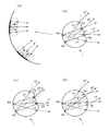
図9(a)は図9(b)〜図9(d)に示した導光体1の第1の光変向面4a及び第2の光変向面4bの拡大図、図9(b)は光出射面5a、5bの一部に平面部を有する本実施形態の発明に係る導光体1の長手方向の一方の端面から見た投影図、図9(c)は光出射面5a、5bの一部に内向する2つの平面部を有する本実施形態の発明に係る導光体1の長手方向の一方の端面から見た投影図、図9(d)は光出射面5a、5bの一部に外向する2つの平面部を有する本実施形態の発明に係る導光体1の長手方向の一方の端面から見た投影図である。なお、これらの図に示される符号の構成は図1に示した同符号の構成に対応する。
図9(a)に示すように、図9(b)〜図9(d)に示す導光体1の第1の光変向面4a及び第2の光変向面4bは、導光体1の半径方向に対して凹面状に形成されている。このように構成することにより、例えば、第1の光変向面4aから放射される光a1〜c1を収束させて光出射面5aに入射させることができる。また、図9(b)〜図9(c)に示すよう、光出射面5a、5bの一部を平面状に形成することにより、光出射面5a、5bからの出射光の収束性は若干犠牲にされるが、光出射面5a、5bからの出射光の光束や方向を任意に制御することができる。
A fourth embodiment of the present invention will be described with reference to FIG.
FIG. 9A is an enlarged view of the first light turning surface 4a and the second
As shown in FIG. 9A, the first light turning surface 4a and the second
本発明の第5の実施形態を図10を用いて説明する。
図10は、1つの光変向面4を有し、光出射面5aと光出射面5bが各々独立した断面が略半円形に形成された本実施形態の発明に係る導光体1の長手方向の一方の端面から見た投影図である。
同図において、4は導光体1の側面に長手方向に伸びる1つの光変向面であり、その他の構成は図1に示した同符号の構成に対応する。
同図に示すように、16aは光出射面5aの法線であり、16bは光出射面5bの法線である。導光体1は法線16a、16bが互いに異なる角度を有する略半円形に形成された2つの曲面、光出射面5aと光出射面5bで構成されている。このように構成することにより、1つの光変向面4から変向され光出射面5a、5bに入射した光は、各々の略半円形に形成された光出射面5aと光出射面5bによって、各々独立して収束され各々異なる方向に出射させることができる。
A fifth embodiment of the present invention will be described with reference to FIG.
FIG. 10 shows the longitudinal direction of the
In the figure,
As shown in the figure, 16a is a normal line of the
1 導光体
2 光入射面
3 他端面
4、4a、4b 光変向面(反射面)
5a、5b 光出射面
6a、6b 突起部
7 光源
8 反射鏡
9 原稿読取面
10 ケース
11 保持部
12 支持部
13、14 窓
DESCRIPTION OF
5a, 5b
Claims (6)
前記導光体は、長手方向に伸びる光変向面と、該光変向面に対向する光出射面とが形成された透明な棒状の導光体であり、前記光変向面は、該光変向面に対する長手方向に伸びる垂直面が交差するように配置された2つの面で形成され、前記光出射面は2つの前記光変向面にそれぞれ対向するように設けられた2つの面で形成されており、
前記LED光源は、前記導光体の長手方向両端の少なくとも一方に設けられた光入射部に対向して設けられており、
前記導光体から出射された光を前記原稿面に向けて反射する前記反射鏡が設けられており、
前記LED光源から前記導光体に入射した光は、前記光変向面で変向され、前記導光体の一方の光出射面から出射される光は前記原稿読取面に向けて出射され、また前記導光体の他方の光出射面から出射される光は前記反射鏡に向けて出射されることを特徴とする原稿読取装置。 An original reading apparatus that includes an LED light source, a light guide that guides light from the LED light source, and a reflecting mirror, and irradiates the original reading surface with light emitted from the light guide.
The light guide is a transparent rod-shaped light guide formed with a light turning surface extending in a longitudinal direction and a light emitting surface facing the light turning surface. Two surfaces are formed by two surfaces arranged so that a vertical surface extending in the longitudinal direction with respect to the light deflecting surface intersects, and the light emitting surface is provided so as to face the two light deflecting surfaces, respectively. Formed with
The LED light source is provided to face a light incident portion provided at at least one of the longitudinal ends of the light guide,
The light emitted from the light guide and the reflector is provided for reflecting the document surface,
Light incident on the light guide from the LED light source is redirected by the light redirecting surface, and light emitted from one light exit surface of the light guide is emitted toward the document reading surface, The document reading apparatus is characterized in that light emitted from the other light emitting surface of the light guide is emitted toward the reflecting mirror.
前記LED光源は、前記導光体の長手方向両端の少なくとも一方に設けられた光入射部に対向して設けられており、
前記導光体は、長手方向に伸びる前記光変向面と、該光変向面に対向する前記光出射面とが形成された透明な棒状の導光体であり、前記光変向面は該光変向面に対する長手方向に伸びる垂直面が交差するように配置された2つの面で形成され、前記光出射面は2つの前記光変向面にそれぞれ対向するように設けられた2つの面で形成されており、
前記反射鏡は、前記導光体の他方の光出射面から出射された光を、導光体の一方の光出射面から出射された光が向かう原稿読取面に向けて反射することを特徴とする、原稿読取装置に用いられる線状光源装置。 The linear light source device is composed of an LED light source, a light guide that guides light from the LED light source, and a reflecting mirror, and light incident on the light guide from the LED light source is redirected by a light redirecting surface. is, light emitted from one of the light emitting surface of the light guide is emitted toward the scanning surface, light emitted from the other light emitting surface of the light guide body the document read by said reflector A linear light source device used for a document reading device reflected toward a surface,
The LED light source is provided to face a light incident portion provided at at least one of the longitudinal ends of the light guide,
The light guide is a transparent rod-shaped light guide in which the light turning surface extending in the longitudinal direction and the light emitting surface facing the light turning surface are formed, and the light turning surface is The light diverting surface is formed by two surfaces arranged so as to intersect with each other in a longitudinal direction extending in the longitudinal direction, and the light emitting surface is provided so as to face the two light diverting surfaces, respectively. Formed with a surface,
The reflecting mirror reflects light emitted from the other light emitting surface of the light guide toward a document reading surface to which light emitted from the one light emitting surface of the light guide travels. A linear light source device used for a document reading device.
Priority Applications (3)
| Application Number | Priority Date | Filing Date | Title |
|---|---|---|---|
| JP2007051039A JP4793288B2 (en) | 2007-03-01 | 2007-03-01 | Light guide and bifurcated linear light source device |
| TW097128810A TW201005204A (en) | 2007-03-01 | 2008-07-30 | Light guiding member and bifurcated linear light source apparatus |
| US12/230,491 US7953312B2 (en) | 2007-03-01 | 2008-08-29 | Light guiding member and bifurcated linear light source apparatus |
Applications Claiming Priority (1)
| Application Number | Priority Date | Filing Date | Title |
|---|---|---|---|
| JP2007051039A JP4793288B2 (en) | 2007-03-01 | 2007-03-01 | Light guide and bifurcated linear light source device |
Publications (2)
| Publication Number | Publication Date |
|---|---|
| JP2008216409A JP2008216409A (en) | 2008-09-18 |
| JP4793288B2 true JP4793288B2 (en) | 2011-10-12 |
Family
ID=39836562
Family Applications (1)
| Application Number | Title | Priority Date | Filing Date |
|---|---|---|---|
| JP2007051039A Active JP4793288B2 (en) | 2007-03-01 | 2007-03-01 | Light guide and bifurcated linear light source device |
Country Status (3)
| Country | Link |
|---|---|
| US (1) | US7953312B2 (en) |
| JP (1) | JP4793288B2 (en) |
| TW (1) | TW201005204A (en) |
Cited By (1)
| Publication number | Priority date | Publication date | Assignee | Title |
|---|---|---|---|---|
| US9188734B2 (en) | 2013-05-31 | 2015-11-17 | Kyocera Document Solutions Inc. | Light guide and illumination device |
Families Citing this family (31)
| Publication number | Priority date | Publication date | Assignee | Title |
|---|---|---|---|---|
| JP5018657B2 (en) * | 2008-02-20 | 2012-09-05 | 三菱電機株式会社 | Illumination device and image reading device |
| JP5012790B2 (en) * | 2008-07-18 | 2012-08-29 | 三菱電機株式会社 | Illumination device and image reading device using the same |
| JP4883063B2 (en) * | 2008-09-21 | 2012-02-22 | ブラザー工業株式会社 | Prism and lighting device |
| JP5360646B2 (en) * | 2008-11-11 | 2013-12-04 | コルコート株式会社 | Line lighting device |
| JP5353556B2 (en) * | 2009-08-21 | 2013-11-27 | ウシオ電機株式会社 | Light source device |
| JP5573107B2 (en) | 2009-11-04 | 2014-08-20 | ウシオ電機株式会社 | Lighting device |
| JP5302864B2 (en) * | 2009-11-27 | 2013-10-02 | 京セラドキュメントソリューションズ株式会社 | Image reading apparatus and image forming apparatus having the same |
| JP5504864B2 (en) * | 2009-12-10 | 2014-05-28 | ウシオ電機株式会社 | Linear light source device |
| JP5071495B2 (en) * | 2010-03-04 | 2012-11-14 | ウシオ電機株式会社 | Light source device |
| CN102271204A (en) * | 2010-06-04 | 2011-12-07 | 株式会社东芝 | Lighting device, image reading device, image forming apparatus and image reading method |
| JP5685903B2 (en) * | 2010-11-26 | 2015-03-18 | 株式会社リコー | Document illumination device, document reading device, and image forming apparatus |
| JP5678638B2 (en) * | 2010-12-16 | 2015-03-04 | コニカミノルタ株式会社 | Image reading illumination device and image reading device |
| US8485675B2 (en) * | 2010-12-28 | 2013-07-16 | Lexmark International, Inc. | Illumination assembly for a scanner |
| US8610969B2 (en) * | 2010-12-28 | 2013-12-17 | Lexmark International, Inc. | Illumination assembly for a scanner with thermally conductive heat sink |
| JP5840367B2 (en) * | 2011-01-31 | 2016-01-06 | ニスカ株式会社 | Illumination apparatus and image reading apparatus using the illumination apparatus |
| TWI427242B (en) * | 2011-03-10 | 2014-02-21 | Lite On Electronics Guangzhou | Linear light source, light guide, and optical scanner module |
| JP2014135117A (en) * | 2011-04-28 | 2014-07-24 | Sharp Corp | Light source device and lighting device including the same |
| JP5963455B2 (en) * | 2012-01-30 | 2016-08-03 | 三菱電機株式会社 | Irradiation apparatus and image reading apparatus |
| JP5712978B2 (en) | 2012-07-26 | 2015-05-07 | コニカミノルタ株式会社 | Light guide, illumination device, and image reading device |
| FR2996649A1 (en) * | 2012-10-04 | 2014-04-11 | Valeo Illuminacion | LIGHTING AND / OR SIGNALING MODULE FOR A VEHICLE COMPRISING A LIGHT GUIDE WITH A RIB AND A SUPPORT WITH FIXING MEANS COOPERATING WITH THE RIB |
| CN108132493B (en) | 2012-12-20 | 2020-11-17 | 三菱电机株式会社 | Image reading apparatus |
| JP5856994B2 (en) | 2013-03-28 | 2016-02-10 | 京セラドキュメントソリューションズ株式会社 | Illumination device, and image reading apparatus and image forming apparatus provided with the same |
| CN105247582B (en) | 2013-04-30 | 2017-11-28 | 光荣株式会社 | Image capturing device and image acquisition method |
| JP5860854B2 (en) | 2013-08-22 | 2016-02-16 | 京セラドキュメントソリューションズ株式会社 | Image reading apparatus and image forming apparatus having the same |
| TWI500982B (en) * | 2013-10-09 | 2015-09-21 | Avision Inc | Dual-slope light guide, light source module and optical assembly for scanner |
| JP6359898B2 (en) * | 2014-07-03 | 2018-07-18 | シャープ株式会社 | Illumination apparatus, image reading apparatus, and image forming apparatus including the same |
| JP6398571B2 (en) * | 2014-10-08 | 2018-10-03 | ウシオ電機株式会社 | Linear light source device for reading |
| US10514487B2 (en) * | 2015-12-17 | 2019-12-24 | 3M Innovative Properties Company | Light guides |
| JP2017118301A (en) | 2015-12-24 | 2017-06-29 | キヤノン株式会社 | Light guide body, illumination device and image reader |
| JP6739138B2 (en) * | 2016-11-30 | 2020-08-12 | ダイハツ工業株式会社 | Lighting equipment |
| CN113037968A (en) * | 2021-03-01 | 2021-06-25 | 维沃移动通信有限公司 | Electronic device |
Family Cites Families (8)
| Publication number | Priority date | Publication date | Assignee | Title |
|---|---|---|---|---|
| JP2000059571A (en) | 1998-08-04 | 2000-02-25 | Fujitsu Ltd | Illuminator |
| JP2001159796A (en) | 1999-12-02 | 2001-06-12 | Canon Inc | Illumination device |
| JP3959678B2 (en) * | 2001-07-13 | 2007-08-15 | ミネベア株式会社 | Touch panel for display device |
| JP2003141904A (en) * | 2001-11-02 | 2003-05-16 | Bridgestone Corp | Linear luminous body |
| JP4047185B2 (en) * | 2003-02-06 | 2008-02-13 | 株式会社小糸製作所 | Vehicle headlamp and light emitting module |
| US7347610B2 (en) * | 2005-01-26 | 2008-03-25 | Radiant Opto-Electronics Corporation | Light guide plate having light diffusing entities on light entering side |
| JP2005229647A (en) | 2005-04-18 | 2005-08-25 | Nippon Sheet Glass Co Ltd | Line lighting device and original reading apparatus |
| US7254309B1 (en) * | 2006-07-14 | 2007-08-07 | Coretronic Corporation | Side emitting LED and lens |
-
2007
- 2007-03-01 JP JP2007051039A patent/JP4793288B2/en active Active
-
2008
- 2008-07-30 TW TW097128810A patent/TW201005204A/en unknown
- 2008-08-29 US US12/230,491 patent/US7953312B2/en active Active
Cited By (1)
| Publication number | Priority date | Publication date | Assignee | Title |
|---|---|---|---|---|
| US9188734B2 (en) | 2013-05-31 | 2015-11-17 | Kyocera Document Solutions Inc. | Light guide and illumination device |
Also Published As
| Publication number | Publication date |
|---|---|
| US7953312B2 (en) | 2011-05-31 |
| TW201005204A (en) | 2010-02-01 |
| JP2008216409A (en) | 2008-09-18 |
| US20090003784A1 (en) | 2009-01-01 |
| TWI379964B (en) | 2012-12-21 |
Similar Documents
| Publication | Publication Date | Title |
|---|---|---|
| JP4793288B2 (en) | Light guide and bifurcated linear light source device | |
| JP5353556B2 (en) | Light source device | |
| US9329333B2 (en) | Irradiation device and image-reading device | |
| JP5216431B2 (en) | Strobe reflector for camera | |
| JPWO2006049206A1 (en) | Illumination device and image reading device using the same | |
| JP5836723B2 (en) | Light guide, illumination device, and image reading device | |
| TW201139939A (en) | Linear light source | |
| JP2000021221A (en) | Linear lighting system | |
| JP5018657B2 (en) | Illumination device and image reading device | |
| CN106895335B (en) | Light emitting module made of transparent material | |
| KR20060023571A (en) | Light guide and image reader | |
| KR101593789B1 (en) | Complex aspherical lens | |
| JP6129602B2 (en) | Document reading light source device | |
| KR101158960B1 (en) | Light guide and two branch line shape light source | |
| US9435509B2 (en) | Linear light source apparatus and image reading apparatus | |
| JP2016134303A (en) | Transparent material, lighting device and image reading device | |
| JP2012059493A (en) | Light source device | |
| JP6128811B2 (en) | Illumination apparatus and image reading apparatus including the same | |
| WO2018207765A1 (en) | Optical element and optical system device | |
| JP2013165411A (en) | Image reader | |
| JP5834974B2 (en) | Image reading device | |
| JP2016213668A (en) | Light guide, illumination apparatus, and image reading apparatus | |
| JP2015119355A (en) | Light guide body, illumination device, and image reader | |
| JP2016110720A (en) | Light guide unit, luminaire including the same and image reading device |
Legal Events
| Date | Code | Title | Description |
|---|---|---|---|
| A621 | Written request for application examination |
Free format text: JAPANESE INTERMEDIATE CODE: A621 Effective date: 20090910 |
|
| A977 | Report on retrieval |
Free format text: JAPANESE INTERMEDIATE CODE: A971007 Effective date: 20101220 |
|
| A131 | Notification of reasons for refusal |
Free format text: JAPANESE INTERMEDIATE CODE: A131 Effective date: 20110125 |
|
| A521 | Request for written amendment filed |
Free format text: JAPANESE INTERMEDIATE CODE: A523 Effective date: 20110317 |
|
| A131 | Notification of reasons for refusal |
Free format text: JAPANESE INTERMEDIATE CODE: A131 Effective date: 20110419 |
|
| A521 | Request for written amendment filed |
Free format text: JAPANESE INTERMEDIATE CODE: A523 Effective date: 20110602 |
|
| TRDD | Decision of grant or rejection written | ||
| A01 | Written decision to grant a patent or to grant a registration (utility model) |
Free format text: JAPANESE INTERMEDIATE CODE: A01 Effective date: 20110628 |
|
| A01 | Written decision to grant a patent or to grant a registration (utility model) |
Free format text: JAPANESE INTERMEDIATE CODE: A01 |
|
| A61 | First payment of annual fees (during grant procedure) |
Free format text: JAPANESE INTERMEDIATE CODE: A61 Effective date: 20110711 |
|
| R150 | Certificate of patent or registration of utility model |
Ref document number: 4793288 Country of ref document: JP Free format text: JAPANESE INTERMEDIATE CODE: R150 Free format text: JAPANESE INTERMEDIATE CODE: R150 |
|
| FPAY | Renewal fee payment (event date is renewal date of database) |
Free format text: PAYMENT UNTIL: 20140805 Year of fee payment: 3 |
|
| R250 | Receipt of annual fees |
Free format text: JAPANESE INTERMEDIATE CODE: R250 |
|
| R250 | Receipt of annual fees |
Free format text: JAPANESE INTERMEDIATE CODE: R250 |
|
| R250 | Receipt of annual fees |
Free format text: JAPANESE INTERMEDIATE CODE: R250 |
|
| R250 | Receipt of annual fees |
Free format text: JAPANESE INTERMEDIATE CODE: R250 |
|
| R250 | Receipt of annual fees |
Free format text: JAPANESE INTERMEDIATE CODE: R250 |
|
| R250 | Receipt of annual fees |
Free format text: JAPANESE INTERMEDIATE CODE: R250 |
|
| R250 | Receipt of annual fees |
Free format text: JAPANESE INTERMEDIATE CODE: R250 |
|
| R250 | Receipt of annual fees |
Free format text: JAPANESE INTERMEDIATE CODE: R250 |