JP4792302B2 - Adaptive controller for periodic signals - Google Patents
Adaptive controller for periodic signals Download PDFInfo
- Publication number
- JP4792302B2 JP4792302B2 JP2006054879A JP2006054879A JP4792302B2 JP 4792302 B2 JP4792302 B2 JP 4792302B2 JP 2006054879 A JP2006054879 A JP 2006054879A JP 2006054879 A JP2006054879 A JP 2006054879A JP 4792302 B2 JP4792302 B2 JP 4792302B2
- Authority
- JP
- Japan
- Prior art keywords
- target value
- filter coefficient
- virtual
- residual
- signal
- Prior art date
- Legal status (The legal status is an assumption and is not a legal conclusion. Google has not performed a legal analysis and makes no representation as to the accuracy of the status listed.)
- Expired - Fee Related
Links
Images
Classifications
-
- G—PHYSICS
- G10—MUSICAL INSTRUMENTS; ACOUSTICS
- G10K—SOUND-PRODUCING DEVICES; METHODS OR DEVICES FOR PROTECTING AGAINST, OR FOR DAMPING, NOISE OR OTHER ACOUSTIC WAVES IN GENERAL; ACOUSTICS NOT OTHERWISE PROVIDED FOR
- G10K11/00—Methods or devices for transmitting, conducting or directing sound in general; Methods or devices for protecting against, or for damping, noise or other acoustic waves in general
- G10K11/16—Methods or devices for protecting against, or for damping, noise or other acoustic waves in general
- G10K11/175—Methods or devices for protecting against, or for damping, noise or other acoustic waves in general using interference effects; Masking sound
- G10K11/178—Methods or devices for protecting against, or for damping, noise or other acoustic waves in general using interference effects; Masking sound by electro-acoustically regenerating the original acoustic waves in anti-phase
- G10K11/1781—Methods or devices for protecting against, or for damping, noise or other acoustic waves in general using interference effects; Masking sound by electro-acoustically regenerating the original acoustic waves in anti-phase characterised by the analysis of input or output signals, e.g. frequency range, modes, transfer functions
- G10K11/17813—Methods or devices for protecting against, or for damping, noise or other acoustic waves in general using interference effects; Masking sound by electro-acoustically regenerating the original acoustic waves in anti-phase characterised by the analysis of input or output signals, e.g. frequency range, modes, transfer functions characterised by the analysis of the acoustic paths, e.g. estimating, calibrating or testing of transfer functions or cross-terms
- G10K11/17815—Methods or devices for protecting against, or for damping, noise or other acoustic waves in general using interference effects; Masking sound by electro-acoustically regenerating the original acoustic waves in anti-phase characterised by the analysis of input or output signals, e.g. frequency range, modes, transfer functions characterised by the analysis of the acoustic paths, e.g. estimating, calibrating or testing of transfer functions or cross-terms between the reference signals and the error signals, i.e. primary path
-
- G—PHYSICS
- G10—MUSICAL INSTRUMENTS; ACOUSTICS
- G10K—SOUND-PRODUCING DEVICES; METHODS OR DEVICES FOR PROTECTING AGAINST, OR FOR DAMPING, NOISE OR OTHER ACOUSTIC WAVES IN GENERAL; ACOUSTICS NOT OTHERWISE PROVIDED FOR
- G10K11/00—Methods or devices for transmitting, conducting or directing sound in general; Methods or devices for protecting against, or for damping, noise or other acoustic waves in general
- G10K11/16—Methods or devices for protecting against, or for damping, noise or other acoustic waves in general
- G10K11/175—Methods or devices for protecting against, or for damping, noise or other acoustic waves in general using interference effects; Masking sound
- G10K11/178—Methods or devices for protecting against, or for damping, noise or other acoustic waves in general using interference effects; Masking sound by electro-acoustically regenerating the original acoustic waves in anti-phase
- G10K11/1781—Methods or devices for protecting against, or for damping, noise or other acoustic waves in general using interference effects; Masking sound by electro-acoustically regenerating the original acoustic waves in anti-phase characterised by the analysis of input or output signals, e.g. frequency range, modes, transfer functions
- G10K11/17821—Methods or devices for protecting against, or for damping, noise or other acoustic waves in general using interference effects; Masking sound by electro-acoustically regenerating the original acoustic waves in anti-phase characterised by the analysis of input or output signals, e.g. frequency range, modes, transfer functions characterised by the analysis of the input signals only
- G10K11/17825—Error signals
-
- G—PHYSICS
- G10—MUSICAL INSTRUMENTS; ACOUSTICS
- G10K—SOUND-PRODUCING DEVICES; METHODS OR DEVICES FOR PROTECTING AGAINST, OR FOR DAMPING, NOISE OR OTHER ACOUSTIC WAVES IN GENERAL; ACOUSTICS NOT OTHERWISE PROVIDED FOR
- G10K11/00—Methods or devices for transmitting, conducting or directing sound in general; Methods or devices for protecting against, or for damping, noise or other acoustic waves in general
- G10K11/16—Methods or devices for protecting against, or for damping, noise or other acoustic waves in general
- G10K11/175—Methods or devices for protecting against, or for damping, noise or other acoustic waves in general using interference effects; Masking sound
- G10K11/178—Methods or devices for protecting against, or for damping, noise or other acoustic waves in general using interference effects; Masking sound by electro-acoustically regenerating the original acoustic waves in anti-phase
- G10K11/1785—Methods, e.g. algorithms; Devices
- G10K11/17853—Methods, e.g. algorithms; Devices of the filter
- G10K11/17854—Methods, e.g. algorithms; Devices of the filter the filter being an adaptive filter
-
- G—PHYSICS
- G10—MUSICAL INSTRUMENTS; ACOUSTICS
- G10K—SOUND-PRODUCING DEVICES; METHODS OR DEVICES FOR PROTECTING AGAINST, OR FOR DAMPING, NOISE OR OTHER ACOUSTIC WAVES IN GENERAL; ACOUSTICS NOT OTHERWISE PROVIDED FOR
- G10K11/00—Methods or devices for transmitting, conducting or directing sound in general; Methods or devices for protecting against, or for damping, noise or other acoustic waves in general
- G10K11/16—Methods or devices for protecting against, or for damping, noise or other acoustic waves in general
- G10K11/175—Methods or devices for protecting against, or for damping, noise or other acoustic waves in general using interference effects; Masking sound
- G10K11/178—Methods or devices for protecting against, or for damping, noise or other acoustic waves in general using interference effects; Masking sound by electro-acoustically regenerating the original acoustic waves in anti-phase
- G10K11/1787—General system configurations
- G10K11/17879—General system configurations using both a reference signal and an error signal
- G10K11/17883—General system configurations using both a reference signal and an error signal the reference signal being derived from a machine operating condition, e.g. engine RPM or vehicle speed
-
- G—PHYSICS
- G10—MUSICAL INSTRUMENTS; ACOUSTICS
- G10K—SOUND-PRODUCING DEVICES; METHODS OR DEVICES FOR PROTECTING AGAINST, OR FOR DAMPING, NOISE OR OTHER ACOUSTIC WAVES IN GENERAL; ACOUSTICS NOT OTHERWISE PROVIDED FOR
- G10K2210/00—Details of active noise control [ANC] covered by G10K11/178 but not provided for in any of its subgroups
- G10K2210/10—Applications
- G10K2210/129—Vibration, e.g. instead of, or in addition to, acoustic noise
- G10K2210/1291—Anti-Vibration-Control, e.g. reducing vibrations in panels or beams
Landscapes
- Physics & Mathematics (AREA)
- Engineering & Computer Science (AREA)
- Acoustics & Sound (AREA)
- Multimedia (AREA)
- Feedback Control In General (AREA)
- Vibration Prevention Devices (AREA)
- Soundproofing, Sound Blocking, And Sound Damping (AREA)
Description
本発明は、振動発生源から発生される周期性信号に対して該周期性信号に同期する適応信号を加えることにより、周期性信号が対象評価点に及ぼす影響を能動的に除去し、対象評価点における振動を低減する周期性信号の適応制御装置に関するものである。 The present invention actively removes the influence of the periodic signal on the target evaluation point by adding an adaptive signal synchronized with the periodic signal to the periodic signal generated from the vibration generation source. The present invention relates to an adaptive control apparatus for periodic signals that reduces vibration at a point.
従来、適応制御装置に関しては、例えば、特開2005−309662号公報に開示されたものがある。当該公報には、振動発生源から発生される信号に対して、適応信号を加えた場合の差分演算値をゼロにするようにすることが記載されている。 Conventionally, an adaptive control device is disclosed in, for example, Japanese Patent Application Laid-Open No. 2005-309661. The gazette describes that a difference calculation value when an adaptive signal is added to a signal generated from a vibration source is set to zero.
このような差分演算値をゼロにするような適応制御装置によれば、確かに、振動発生源から対象評価点までの伝達経路が一つのみの場合には、対象評価点における振動をゼロにするようにすることができる。 According to such an adaptive control device that sets the difference calculation value to zero, if there is only one transmission path from the vibration source to the target evaluation point, the vibration at the target evaluation point is reduced to zero. To be able to.
しかし、振動発生源から対象評価点までの伝達経路が複数存在する場合に、複数の伝達経路のうち一の伝達経路の振動に対して適応制御装置を適用すると、以下のような問題が生じる。 However, when there are a plurality of transmission paths from the vibration source to the target evaluation point, if the adaptive control device is applied to the vibration of one transmission path among the plurality of transmission paths, the following problems occur.
第1に、仮に適応制御を適用しない場合には、複数の伝達経路を介して伝達された振動が、相互に打ち消し合うことで、結果的に対象評価点における振動が低減することがある。このような場合に、一の伝達経路に対して適応制御装置を適用すると、一の伝達経路の振動は低減するため、他の伝達経路の振動を打ち消すように作用しない。その結果、却って対象評価点における振動が大きくなるおそれがある。 First, if adaptive control is not applied, vibrations transmitted through a plurality of transmission paths cancel each other, resulting in a reduction in vibration at the target evaluation point. In such a case, when the adaptive control device is applied to one transmission path, the vibration of one transmission path is reduced, so that it does not act to cancel the vibration of the other transmission path. As a result, the vibration at the target evaluation point may increase.
第2に、複数の伝達経路を介して伝達される振動が、それぞれ周波数毎に対象評価点への寄与の割合が異なることがある。例えば、一の伝達経路に対して適応制御装置を適用する場合に、当該一の伝達経路の振動の寄与が高い周波数においては、対象評価点における振動を大きく低減することができる。しかし、他の周波数帯においては、一の伝達経路に対して適用制御装置を適用したとしても、対象評価点における振動をそれほど低減することができない場合がある。そうすると、周波数毎に振動の低減量が異なるため、周波数の変化に対して振動の変化割合が大きくなることがある。つまり、振動の山谷のギャップが大きくなる。このような変化は、人にとって違和感を受ける。 Second, vibrations transmitted through a plurality of transmission paths may have different contribution ratios to the target evaluation point for each frequency. For example, when the adaptive control device is applied to one transmission path, the vibration at the target evaluation point can be greatly reduced at a frequency where the vibration contribution of the one transmission path is high. However, in other frequency bands, even if the application control device is applied to one transmission path, vibration at the target evaluation point may not be reduced so much. Then, since the amount of vibration reduction differs for each frequency, the vibration change rate may increase with respect to the frequency change. That is, the gap between the peaks and valleys of vibration becomes large. Such changes are uncomfortable for people.
また、近年、振動・騒音などを利用して音色作りが注目されている。しかし、従来の適応制御装置を適用すると、対象評価点における振動・騒音をゼロにするようにしているので、音色作りを行う際には新たに振動を発生させることが必要となる。そのため、エネルギー効率が非常に悪い。 In recent years, attention has been focused on making timbres using vibration and noise. However, when the conventional adaptive control device is applied, the vibration / noise at the target evaluation point is made zero, so that it is necessary to newly generate vibration when making a timbre. Therefore, energy efficiency is very bad.
本発明は、このような事情に鑑みてなされたものであり、周期性信号に対して適応信号を加えた場合に、その残差が意図的にゼロにならないようにすることができる周期性信号の適応制御装置を提供することを目的とする。 The present invention has been made in view of such circumstances. When an adaptive signal is added to a periodic signal, the periodic signal can prevent the residual from intentionally becoming zero. It is an object of the present invention to provide an adaptive control apparatus.
本発明の周期性信号の適応制御装置は、振動発生源から発生される周期性信号に対して該周期性信号に同期する適応信号を加えることにより、周期性信号が所定の伝達経路を経由して対象評価点に及ぼす影響を能動的に低減する周期性信号の適応制御装置である。ここで、所定の伝達経路は、第1伝達経路及び前記第1伝達経路と異なる第2伝達経路を含む。そして、周期性信号の適応制御装置は、周期性信号のうち特定周波数成分の角振動数に基づき、第1振幅フィルタ係数及び第1位相フィルタ係数を構成成分に含む適応信号を第1伝達経路中に発生させる適応信号発生部と、第1伝達経路中のうち適応信号発生部と対象評価点との間に位置する第1観測点において、周期性信号に対して適応信号を所定の第1伝達特性を介して加えることにより生じる第1の残差を検出する第1残差検出部と、少なくとも角振動数に応じた振幅目標値を含む第1観測点の周期性の残差目標値であって、角振動数および第2伝達経路の伝達特性に基づき残差目標値を設定する観測点目標値設定部と、角振動数、第1の残差及び残差目標値に基づき第1振幅フィルタ係数及び第1位相フィルタ係数を更新する第1フィルタ係数更新部とを備えることを特徴とする。 The adaptive control apparatus for a periodic signal according to the present invention adds an adaptive signal synchronized with the periodic signal to the periodic signal generated from the vibration source, so that the periodic signal passes through a predetermined transmission path. This is an adaptive control device for periodic signals that actively reduces the influence on the target evaluation points. Here, the predetermined transmission path includes a first transmission path and a second transmission path different from the first transmission path. Then, the adaptive control device for the periodic signal includes an adaptive signal in the first transmission path that includes the first amplitude filter coefficient and the first phase filter coefficient as constituent components based on the angular frequency of the specific frequency component of the periodic signal. An adaptive signal is generated in response to a periodic signal at a first observation point located between the adaptive signal generator and the target evaluation point in the first transmission path. A first residual detection unit that detects a first residual generated by adding the characteristic, and a periodic residual target value of a first observation point that includes at least an amplitude target value corresponding to the angular frequency. An observation point target value setting unit for setting a residual target value based on the angular frequency and the transmission characteristic of the second transmission path, and a first amplitude filter based on the angular frequency, the first residual and the residual target value A first block for updating the coefficient and the first phase filter coefficient; Characterized in that it comprises a filter coefficient updating unit.
本発明の周期性信号の適応制御装置によれば、周期性の残差目標値を用いて第1振幅フィルタ係数及び第1位相フィルタ係数を更新している。そして、更新された各フィルタ係数を用いた適応信号が発生される。つまり、第1観測点における残差をゼロにするのではなく、第1観測点における残差が残差目標値になるように、適応信号発生部が適応信号を発生している。ここで、残差目標値は、振幅目標値を振幅とする周期性の信号である。従って、振動発生源から対象評価点までの伝達経路が複数存在する場合に、却って対象評価点における振動が大きくなることを抑制することができ、且つ、振動の山谷のギャップを小さくすることができる。さらに、音色作りを行う際に、残差目標値に相当する信号を利用することができるので、エネルギー効率が向上する。 According to the periodic signal adaptive control apparatus of the present invention, the first amplitude filter coefficient and the first phase filter coefficient are updated using the periodic residual target value. Then, an adaptive signal using each updated filter coefficient is generated. That is, the adaptive signal generator generates the adaptive signal so that the residual at the first observation point does not become zero but the residual at the first observation point becomes the residual target value. Here, the residual target value is a periodic signal whose amplitude is the amplitude target value. Therefore, when there are a plurality of transmission paths from the vibration source to the target evaluation point, it is possible to suppress the vibration at the target evaluation point from increasing, and to reduce the gap between the peaks and valleys of the vibration. . Furthermore, since the signal corresponding to the residual target value can be used when making a timbre, energy efficiency is improved.
また、残差目標値は、角振動数に応じた位相目標値を含むようにしてもよい。すなわち、この場合の残差目標値は、角振動数に応じた振幅目標値及び位相目標値を含むことになる。つまり、第1観測点における残差目標値の位相が、振動発生源から発生される周期性信号の位相に対して異ならせることができる。 Further, the residual target value may include a phase target value corresponding to the angular frequency. That is, the residual target value in this case includes an amplitude target value and a phase target value corresponding to the angular frequency. That is, the phase of the residual target value at the first observation point can be made different from the phase of the periodic signal generated from the vibration source.
例えば、振動発生源から対象評価点までの伝達経路が複数存在する場合に、一の伝達経路を介して伝達された振動の位相と、他の伝達経路を介して伝達された振動の位相とは、異なることがある。そして、一の伝達経路を介して伝達される振動に対して適応信号を発生した場合に、一の伝達経路における第1観測点の残差の位相が、他の伝達経路を介して伝達される振動の位相に一致させることが最も望ましい。そこで、残差目標値に位相目標値を含ませることで、第1観測点における残差の位相を適宜調整することができる。従って、確実に、複数の伝達経路が存在する場合に、対象評価点における振動を抑制するように制御できる。 For example, when there are multiple transmission paths from the vibration source to the target evaluation point, the phase of vibration transmitted through one transmission path and the phase of vibration transmitted through another transmission path May be different. Then, when an adaptive signal is generated for vibration transmitted through one transmission path, the phase of the residual at the first observation point in one transmission path is transmitted through the other transmission path. It is most desirable to match the phase of vibration. Therefore, the phase of the residual at the first observation point can be adjusted as appropriate by including the phase target value in the residual target value. Therefore, when there are a plurality of transmission paths, it is possible to control to suppress the vibration at the target evaluation point.
ここで、残差目標値に振幅目標値を含む場合には、第1フィルタ係数更新部による第1振幅フィルタ係数及び第1位相フィルタ係数の更新は、以下のようにするとよい。 Here, when the amplitude target value is included in the residual target value, the update of the first amplitude filter coefficient and the first phase filter coefficient by the first filter coefficient update unit may be performed as follows.
すなわち、本発明の周期性信号の適応制御装置は、角振動数に基づき第1伝達特性の伝達関数の推定値を算出する第1推定伝達関数算出部をさらに備え、適応信号発生部は、式(1)に従って得られる適応信号を第1伝達経路中に発生させ、第1フィルタ係数更新部は、角振動数、第1の残差、第1伝達関数推定値、及び、残差目標値に基づき、式(2)(3)(4)又は式(5)(6)(7)に従って式(1)における第1振幅フィルタ係数及び第1位相フィルタ係数を更新する。 That is, the periodic signal adaptive control apparatus of the present invention further includes a first estimated transfer function calculating unit that calculates an estimated value of the transfer function of the first transfer characteristic based on the angular frequency, and the adaptive signal generating unit An adaptive signal obtained according to (1) is generated in the first transmission path, and the first filter coefficient update unit generates an angular frequency, a first residual, a first transfer function estimated value, and a residual target value. Based on Formula (2) (3) (4) or Formula (5) (6) (7), the first amplitude filter coefficient and the first phase filter coefficient in Formula (1) are updated.

ここで、第1振幅フィルタ係数及び第1位相フィルタ係数の更新に際して、式(2)(3)(4)に従って更新する場合と、式(5)(6)(7)に従って更新する場合とがあるが、これらは何れも収束性はほとんど変わらない。しかし、第1位相フィルタ係数の更新式(3)には、第1伝達特性G1の伝達関数の推定値Gh1の振幅成分Ah1及び第1振幅フィルタ係数a1nが含まれていない。一方、第1位相フィルタ係数の更新式(6)には、第1伝達特性G1の伝達関数の推定値Gh1の振幅成分Ah1及び第1振幅フィルタ係数a1nが含まれている。従って、第1位相フィルタ係数の更新に際して、式(3)を用いる場合には、式(6)を用いる場合に比べて、演算負荷を低減できる。その結果、演算処理能力の低いマイクロコンピュータを用いることができ、低コスト化を図ることができる。 Here, when updating the first amplitude filter coefficient and the first phase filter coefficient, there are a case where updating is performed according to Expressions (2), (3) and (4) and a case where updating is performed according to Expressions (5), (6) and (7). However, the convergence of these is almost the same. However, the update equation (3) for the first phase filter coefficient does not include the amplitude component Ah1 and the first amplitude filter coefficient a1 n of the estimated value Gh1 of the transfer function of the first transfer characteristic G1. On the other hand, the update equation (6) of the first phase filter coefficient includes the amplitude component Ah1 of the estimated transfer function Gh1 of the first transfer characteristic G1 and the first amplitude filter coefficient a1 n . Therefore, when updating the first phase filter coefficient, the calculation load can be reduced in the case where Expression (3) is used compared to the case where Expression (6) is used. As a result, a microcomputer with low arithmetic processing capability can be used, and cost reduction can be achieved.
また、残差目標値に振幅目標値及び位相目標値を含む場合には、第1フィルタ係数更新部による第1振幅フィルタ係数及び第1位相フィルタ係数の更新は、以下のようにするとよい。 In addition, when the residual target value includes the amplitude target value and the phase target value, the first amplitude filter coefficient and the first phase filter coefficient may be updated by the first filter coefficient updating unit as follows.
すなわち、本発明の周期性信号の適応制御装置は、角振動数に基づき第1伝達特性の伝達関数の推定値を算出する第1推定伝達関数算出部をさらに備え、適応信号発生部は、式(8)に従って得られる適応信号を第1伝達経路中に発生させ、第1フィルタ係数更新部は、角振動数、第1の残差、第1伝達関数推定値、及び、残差目標値に基づき、式(9)(10)(11)又は式(12)(13)(14)に従って式(8)における第1振幅フィルタ係数及び第1位相フィルタ係数を更新する。 That is, the periodic signal adaptive control apparatus of the present invention further includes a first estimated transfer function calculating unit that calculates an estimated value of the transfer function of the first transfer characteristic based on the angular frequency, and the adaptive signal generating unit An adaptive signal obtained according to (8) is generated in the first transmission path, and the first filter coefficient update unit sets the angular frequency, the first residual, the first transfer function estimated value, and the residual target value. Based on the equations (9), (10), (11) or the equations (12), (13), and (14), the first amplitude filter coefficient and the first phase filter coefficient in the equation (8) are updated.
ここで、第1振幅フィルタ係数及び第1位相フィルタ係数の更新に際して、式(9)(10)(11)に従って更新する場合と、式(12)(13)(14)に従って更新する場合とがあるが、これらは何れも収束性はほとんど変わらない。しかし、第1位相フィルタ係数の更新式(10)には、第1伝達特性G1の伝達関数の推定値Gh1の振幅成分Ah1及び第1振幅フィルタ係数a1nが含まれていない。一方、第1位相フィルタ係数の更新式(13)には、第1伝達特性G1の伝達関数の推定値Gh1の振幅成分Ah1及び第1振幅フィルタ係数a1nが含まれている。従って、第1位相フィルタ係数の更新に際して、式(10)を用いる場合には、式(13)を用いる場合に比べて、演算負荷を低減できる。その結果、演算処理能力の低いマイクロコンピュータを用いることができ、低コスト化を図ることができる。 Here, when updating the first amplitude filter coefficient and the first phase filter coefficient, there are a case where updating is performed according to Expressions (9), (10) and (11) and a case where updating is performed according to Expressions (12), (13) and (14). However, the convergence of these is almost the same. However, the update equation (10) for the first phase filter coefficient does not include the amplitude component Ah1 and the first amplitude filter coefficient a1 n of the estimated value Gh1 of the transfer function of the first transfer characteristic G1. On the other hand, the update equation (13) for the first phase filter coefficient includes the amplitude component Ah1 and the first amplitude filter coefficient a1 n of the estimated value Gh1 of the transfer function of the first transfer characteristic G1. Therefore, when updating the first phase filter coefficient, the calculation load can be reduced in the case where Expression (10) is used, compared to the case where Expression (13) is used. As a result, a microcomputer with low arithmetic processing capability can be used, and cost reduction can be achieved.
また、本発明において、観測点目標値設定部は、第2伝達経路の伝達特性に基づき振幅目標値を設定している。これにより、第2伝達経路を介して対象評価点に伝達された振動に対して、第1伝達経路中の第1観測点における残差の振幅を適切に調整することができる。従って、第2伝達経路を介して伝達された振動に対して相互に打ち消し合うようにすることができ、結果として対象評価点における振動を低減することができる。 In the present invention, the observation point target value setting unit sets the amplitude target value based on the transfer characteristic of the second transfer path . Thereby, the amplitude of the residual at the first observation point in the first transmission path can be appropriately adjusted with respect to the vibration transmitted to the target evaluation point via the second transmission path. Therefore, the vibrations transmitted through the second transmission path can be canceled with each other, and as a result, the vibration at the target evaluation point can be reduced.
そして、第2伝達経路の伝達特性に基づき振幅目標値を設定する場合には、以下の2通りがある。 Then, when setting the amplitude target value based on the transfer characteristic of the second transfer path, there are the following two methods.
振幅目標値を設定する第1番目の手段は、観測点目標値設定部は、角振動数に応じた振幅目標値を予め記憶し、振動発生源から実際に発生される周期性信号の角振動数に基づき振幅目標値を設定するようにする。つまり、予め角振動数毎の振幅目標値をマップなどとして記憶しておき、周期性信号の角振動数のみに基づき振幅目標値が設定される。これにより、非常に高速に振幅目標値を設定することができる。 The first means for setting the amplitude target value is that the observation point target value setting unit stores the amplitude target value corresponding to the angular frequency in advance and the angular vibration of the periodic signal actually generated from the vibration source. An amplitude target value is set based on the number. That is, the target amplitude value for each angular frequency is stored in advance as a map or the like, and the target amplitude value is set based only on the angular frequency of the periodic signal. Thereby, the amplitude target value can be set very quickly.
また、振幅目標値を設定する第2番目の手段は、適応的に振幅目標値を設定する方法である。この第2番目の手段は、以下の通りである。すなわち、観測点目標値設定部は、角振動数に基づき、第2振幅フィルタ係数及び第2位相フィルタ係数を構成成分に含む式(15)に従って得られる仮想適応信号を第2伝達経路中に仮想的に発生させる仮想適応信号発生部と、第2伝達経路中の第2観測点において周期性信号に基づき生じる第2観測点振動を検出する振動検出部と、仮想適応信号及び第2観測点振動に基づき、仮想観測点において周期性信号に対して仮想適応信号を所定の仮想伝達特性を介して仮想的に加えることにより生じる仮想残差を検出する仮想残差検出部と、角振動数に基づき仮想伝達特性の伝達関数の推定値を算出する仮想伝達関数推定部と、角振動数、仮想残差及び仮想伝達関数推定値に基づき、式(16)(17)又は式(18)(19)に従って式(15)における第2振幅フィルタ係数及び第2位相フィルタ係数を更新する第2フィルタ係数更新部と、更新された第2振幅フィルタ係数を式(20)に従って振幅目標値に設定する更新目標値設定部と、を備える。 The second means for setting the amplitude target value is a method for adaptively setting the amplitude target value. The second means is as follows. That is, the observation point target value setting unit virtually transmits a virtual adaptive signal obtained in accordance with the equation (15) including the second amplitude filter coefficient and the second phase filter coefficient in the component based on the angular frequency in the second transmission path. A virtual adaptive signal generating unit that is generated automatically, a vibration detecting unit that detects a second observation point vibration generated based on a periodic signal at a second observation point in the second transmission path, a virtual adaptive signal, and a second observation point vibration Based on the angular frequency, a virtual residual detector that detects a virtual residual generated by virtually adding a virtual adaptive signal to a periodic signal via a predetermined virtual transfer characteristic at a virtual observation point Based on a virtual transfer function estimator that calculates an estimated value of the transfer function of the virtual transfer characteristic, the angular frequency, the virtual residual, and the virtual transfer function estimated value, Expressions (16), (17), or (18) (19) According to the formula (1 ), A second filter coefficient updating unit that updates the second amplitude filter coefficient and the second phase filter coefficient, and an updated target value setting unit that sets the updated second amplitude filter coefficient to the amplitude target value according to Expression (20); .
![]()
![]()
このように振幅目標値を適応的に設定することで、より高精度に、第2伝達特性に応じた振幅目標値とすることができる一方、演算処理の高速化が要求される。 By setting the amplitude target value adaptively in this way, it is possible to obtain the amplitude target value according to the second transfer characteristic with higher accuracy, while speeding up the arithmetic processing is required.
また、振動発生源から対象評価点までの所定の伝達経路が、第1伝達経路及び第1伝達経路と異なる第2伝達経路を含む場合に、観測点目標値設定部は、第2伝達経路の伝達特性に基づき位相目標値を設定するようにするとよい。これにより、第2伝達経路を介して対象評価点に伝達された振動に対して、第1伝達経路中の第1観測点における残差の位相を適切に調整することができる。従って、第2伝達経路を介して伝達された振動に対して相互に打ち消し合うようにすることができ、結果として対象評価点における振動を低減することができる。 When the predetermined transmission path from the vibration source to the target evaluation point includes a first transmission path and a second transmission path different from the first transmission path, the observation point target value setting unit The phase target value may be set based on the transfer characteristics. Thereby, the phase of the residual at the first observation point in the first transmission path can be appropriately adjusted with respect to the vibration transmitted to the target evaluation point via the second transmission path. Therefore, the vibrations transmitted through the second transmission path can be canceled with each other, and as a result, the vibration at the target evaluation point can be reduced.
そして、第2伝達経路の伝達特性に基づき位相目標値を設定する場合には、以下の2通りがある。 Then, when setting the phase target value based on the transfer characteristic of the second transfer path, there are the following two types.
位相目標値を設定する第1番目の手段は、観測点目標値設定部は、角振動数に応じた位相目標値を予め記憶し、振動発生源から実際に発生される周期性信号の角振動数に基づき位相目標値を設定するようにする。つまり、予め角振動数毎の位相目標値をマップなどとして記憶しておき、周期性信号の角振動数のみに基づき位相目標値が設定される。これにより、非常に高速に位相目標値を設定することができる。 The first means for setting the phase target value is that the observation point target value setting unit stores the phase target value corresponding to the angular frequency in advance, and the angular vibration of the periodic signal actually generated from the vibration source. The phase target value is set based on the number. That is, the phase target value for each angular frequency is stored in advance as a map or the like, and the phase target value is set based only on the angular frequency of the periodic signal. Thereby, the phase target value can be set very quickly.
また、位相目標値を設定する第2番目の手段は、適応的に位相目標値を設定する方法である。この第2番目の手段は、以下の通りである。すなわち、観測点目標値設定部は、角振動数に基づき、第2振幅フィルタ係数及び第2位相フィルタ係数を構成成分に含む式(21)に従って得られる仮想適応信号を第2伝達経路中に仮想的に発生させる仮想適応信号発生部と、第2伝達経路中の第2観測点において周期性信号に基づき生じる第2観測点振動を検出する振動検出部と、仮想適応信号及び第2観測点振動に基づき、仮想観測点において周期性信号に対して仮想適応信号を所定の仮想伝達特性を介して仮想的に加えることにより生じる仮想残差を検出する仮想残差検出部と、角振動数に基づき仮想伝達特性の伝達関数の推定値を算出する仮想伝達関数推定部と、角振動数、仮想残差及び仮想伝達関数推定値に基づき、式(22)(23)又は式(24)(25)に従って式(21)における第2振幅フィルタ係数及び第2位相フィルタ係数を更新する第2フィルタ係数更新部と、更新された第2位相フィルタ係数を式(26)に従って位相目標値に設定する更新目標値設定部と、を備える。 The second means for setting the phase target value is a method for adaptively setting the phase target value. The second means is as follows. In other words, the observation point target value setting unit virtually transmits the virtual adaptive signal obtained according to the equation (21) including the second amplitude filter coefficient and the second phase filter coefficient as constituent components in the second transmission path based on the angular frequency. A virtual adaptive signal generating unit that is generated automatically, a vibration detecting unit that detects a second observation point vibration generated based on a periodic signal at a second observation point in the second transmission path, a virtual adaptive signal, and a second observation point vibration Based on the angular frequency, a virtual residual detector that detects a virtual residual generated by virtually adding a virtual adaptive signal to a periodic signal via a predetermined virtual transfer characteristic at a virtual observation point Based on a virtual transfer function estimator that calculates an estimated value of the transfer function of the virtual transfer characteristic, and the angular frequency, the virtual residual, and the virtual transfer function estimated value, the equations (22) (23) or (24) (25) According to formula (2 ), A second filter coefficient updating unit that updates the second amplitude filter coefficient and the second phase filter coefficient, and an updated target value setting unit that sets the updated second phase filter coefficient to the phase target value according to Expression (26); .
![]()
![]()
このように位相目標値を適応的に設定することで、より高精度に、第2伝達特性に応じた位相目標値とすることができる一方、演算処理の高速化が要求される。 By adaptively setting the phase target value in this way, the phase target value corresponding to the second transfer characteristic can be obtained with higher accuracy, while speeding up the arithmetic processing is required.
本発明の周期性信号の適応制御装置によれば、周期性信号に対して適応信号を加えた場合に、その残差が意図的にゼロにならないようにすることができる。従って、振動発生源から対象評価点までの伝達経路が複数存在する場合に、却って対象評価点における振動が大きくなることを抑制することができ、且つ、振動の山谷のギャップを小さくすることができる。さらに、音色作りを行う際に、残差目標値に相当する信号を利用することができるので、エネルギー効率が向上する。 According to the adaptive control apparatus for periodic signals of the present invention, when an adaptive signal is added to a periodic signal, the residual can be prevented from intentionally becoming zero. Therefore, when there are a plurality of transmission paths from the vibration source to the target evaluation point, it is possible to suppress the vibration at the target evaluation point from increasing, and to reduce the gap between the peaks and valleys of the vibration. . Furthermore, since the signal corresponding to the residual target value can be used when making a timbre, energy efficiency is improved.
次に、実施形態を挙げ、本発明をより詳しく説明する。 Next, the present invention will be described in more detail with reference to embodiments.
(1)周期性信号の適応制御装置1の概略説明
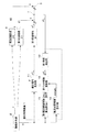
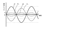
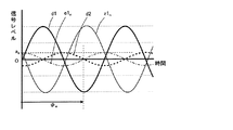
周期性信号の適応制御装置1(以下、「適応制御装置」という)の概略について、図1〜図3を参照して説明する。図1は、第1実施形態及び第2実施形態の周期性信号の適応制御装置1のブロック図を示す。図2は、位相目標値を設定していない場合について説明する図である。図3は、位相目標値を設定した場合について説明する図である。
(1) Schematic Description of Periodic Signal Adaptive Control Device 1 An overview of a periodic signal adaptive control device 1 (hereinafter referred to as “adaptive control device”) will be described with reference to FIGS. FIG. 1 shows a block diagram of an adaptive control apparatus 1 for periodic signals according to the first embodiment and the second embodiment. FIG. 2 is a diagram illustrating a case where the phase target value is not set. FIG. 3 is a diagram illustrating a case where a phase target value is set.
まずは、適応制御装置1を機能させていない場合について説明する。振動発生源2から周期性信号fが発生される。この周期性信号fは、対象評価点3まで伝達される。そして、振動発生源2から対象評価点3までの伝達経路は、第1伝達経路4と第2伝達経路5とが存在する。
First, a case where the adaptive control device 1 is not functioning will be described. A periodic signal f is generated from the
そして、適応制御装置1を機能させた場合には、次のようになる。適応制御装置1は、第1伝達経路4中に適応信号y1nを発生させている。そして、発生された適応信号y1nは、第1伝達特性G1を介することで、信号z1nとなり、当該信号z1nを周期性信号成分d1に合成させる。ここで、適応制御装置1は、第1観測点7における残差e1nが後述する残差目標値etargetnに一致するようにされる。なお、第1観測点7は、第1伝達経路中のうち後述する適応信号発生部11と対象評価点3との間に位置する。
And when the adaptive control apparatus 1 is made to function, it becomes as follows. The adaptive control device 1 generates an adaptive signal y1 n in the
次に、対象評価点3における信号レベルをゼロにすることを目標とした場合に、適応制御装置1がどのような適応信号ynを発生させるべきかについて、図2及び図3を参照しながら説明する。 Then, when targeted to the signal level in the subject evaluation point 3 zero, whether to adaptive controller 1 generates the any adaptive signal y n, with reference to FIGS. 2 and 3 explain.
図2及び図3において、第1伝達経路4を介して伝達される周期性信号成分d1(以下、「第1伝達信号成分」という)を太実線により示し、第2伝達経路5を介して伝達される周期性信号成分d2(以下、「第2伝達信号成分」という)を太破線により示す。そして、適応制御装置1が発生する適応信号ynが第1伝達特性G1を介した信号z1n(以下、「適応伝達信号」という)を細実線により示し、第1観測点7における残差e1nを細一点鎖線により示す。
In FIG. 2 and FIG. 3, the periodic signal component d <b> 1 (hereinafter referred to as “first transmission signal component”) transmitted via the
図2においては、第1伝達信号成分d1は、第2伝達信号成分d2に対して、振幅が約3倍であり、位相が180度異なる信号成分からなる。このような場合に、対象評価点3における信号レベルをゼロにするためには、第1観測点7における残差e1nを、第2伝達信号成分d2に対して、振幅が同一であり、位相が180度異なる信号成分にするとよい。そして、第1観測点7における残差e1nは、第1伝達信号成分d1と適応伝達信号z1nとの合成信号であるので、適応伝達信号z1nは、第1観測点7における残差e1nから第1伝達信号成分d1を減算した信号となる。
In FIG. 2, the first transmission signal component d1 is composed of signal components having an amplitude approximately three times that of the second transmission signal component d2 and having a phase different by 180 degrees. In such a case, in order to make the signal level at the target evaluation point 3 zero, the residual e1 n at the
この場合の適応伝達信号z1nは、第1伝達信号成分d1に対して、振幅が約3分の2であり、位相が180度異なる信号成分からなる。そして、適応制御装置1は、第1伝達特性G1を介した信号が上記のような適応伝達信号z1nとなるような適応信号y1nを発生させるとよい。 The adaptive transmission signal z1 n in this case is composed of signal components having an amplitude that is about two-thirds of the first transmission signal component d1 and 180 degrees out of phase. Then, the adaptive control device 1 may generate an adaptive signal y1 n such that the signal transmitted through the first transfer characteristic G1 becomes the adaptive transfer signal z1 n as described above.
図3においては、第1伝達信号成分d1は、第2伝達信号成分d2に対して、振幅が約3倍であり、位相が90度異なる信号成分からなる。このような場合に、対象評価点3における信号レベルをゼロにするためには、第1観測点7における残差e1nを、第2伝達信号成分d2に対して、振幅が同一であり、位相が180度異なる信号成分にするとよい。そして、第1観測点7における残差e1nは、第1伝達信号成分d1と適応伝達信号z1nとの合成信号であるので、適応伝達信号z1nは、第1観測点7における残差e1nから第1伝達信号成分d1を減算した信号となる。
In FIG. 3, the first transmission signal component d1 is composed of signal components having an amplitude that is approximately three times that of the second transmission signal component d2 and that is 90 degrees out of phase. In such a case, in order to make the signal level at the target evaluation point 3 zero, the residual e1 n at the
この場合の適応伝達信号z1nは、第1伝達信号成分d1に対して、振幅が僅かに大きくなり、位相が180度より僅かに大きな角度異なる信号成分からなる。そして、適応制御装置1は、第1伝達特性G1を介した信号が上記のような適応伝達信号z1nとなるような適応信号y1nを発生させるとよい。 The adaptive transmission signal z1 n in this case is composed of signal components whose amplitude is slightly larger than that of the first transmission signal component d1 and whose phase is slightly different from that of 180 degrees. Then, the adaptive control device 1 may generate an adaptive signal y1 n such that the signal transmitted through the first transfer characteristic G1 becomes the adaptive transfer signal z1 n as described above.
(2)第1実施形態の適応制御装置1の詳細構成
次に、第1実施形態の適応制御装置1の詳細構成について、図1を参照して説明する。ここで、第1実施形態の適応制御装置1は、残差目標値etargetnが予め記憶されている場合であって、残差目標値etargetnには振幅目標値aeを含むが、位相目標値φeを含まない場合である。
(2) Detailed Configuration of Adaptive Control Device 1 of First Embodiment Next, a detailed configuration of the adaptive control device 1 of the first embodiment will be described with reference to FIG. Here, the adaptive control apparatus 1 of the first embodiment is a case where the residual target value etarget n is stored in advance, and the residual target value etarget n includes the amplitude target value a e , but the phase target. a case which does not include the value phi e.
第1実施形態の適応制御装置1は、図1に示すように、適応信号発生部11と、第1残差検出部12と、第1推定伝達関数算出部13と、観測点目標値設定部14と、第1フィルタ係数更新部15とから構成される。
As shown in FIG. 1, the adaptive control device 1 of the first embodiment includes an adaptive
適応信号発生部11は、振動発生源2から発生される周期性信号fの一次周波数成分の角振動数ωに基づき、式(51)に従って得られる適応信号ynを第1伝達経路4中に発生させる。ここで、適応信号ynは、式(51)より明らかなように、第1振幅フィルタ係数a1n及び第1位相フィルタ係数φ1nを構成成分に含む一次正弦波からなる。そして、第1振幅フィルタ係数a1n及び第1位相フィルタ係数φ1nは、第1フィルタ係数更新部15により適応的に更新される。
Adaptive
第1残差検出部12は、第1観測点7における残差e1nを検出する。残差e1nは、式(52)に示すように、周期性信号fが第1伝達経路4を介して伝達される周期性信号成分d1に、適応伝達信号z1nを加えることにより生じる信号である。ここで、適応伝達信号z1nは、適応信号y1nが第1伝達特性G1を介して伝達された信号である。
The first
![]()
![]()
第1推定伝達関数算出部13は、振動発生源2から発生される周期性信号fの一次周波数成分の角振動数ωに基づき、第1伝達特性G1の伝達関数の推定値Gh1を算出する。この第1伝達特性G1の伝達関数は、振幅成分と位相成分とが含まれている。つまり、第1推定伝達関数算出部13は、第1伝達特性G1の伝達関数の振幅成分の推定値Ah1と、位相成分の推定値Φh1とを算出する。例えば、第1推定伝達関数算出部13は、予め、角振動数ωに応じたそれぞれの推定値Ah1、Φh1をマップなどとして記憶しておくようにしてもよい。この場合、実際に振動発生源2から発生された周期性信号fの角振動数ωと、記憶されているマップデータとにより、それぞれの推定値Ah1、Φh1を決定する。
The first estimated transfer
観測点目標値設定部14は、角振動数ωに基づき残差目標値etargetnを設定する。この残差目標値etargetnは、第1観測点7における周期性の成分からなり、第1実施形態においては、式(53)のように示される。式(53)に示すように、残差目標値etargetnは、振幅目標値aeを含み、周期性信号fの位相と同位相となる。そして、振幅目標値aeは、角振動数ωに応じて異なるように設定されている。具体的には、振幅目標値aeは、第2周期性信号fが第2伝達経路5を介して対象評価点3に伝達される振幅成分に応じて決定している。すなわち、対象評価点3において、信号レベルが小さくなるように、且つ、周波数毎における信号レベルの山谷の差が小さくなるように設定している。
The observation point target
第1フィルタ係数更新部15は、角振動数ω、第1観測点7における残差e1n、第1伝達関数推定値Gh1(Ah1、Φh1)及び残差目標値etargetnに基づき、式(54)(55)に従って、第1振幅フィルタ係数a1n及び第1位相フィルタ係数φ1nを更新する。そして、第1フィルタ係数更新部15により更新された第1振幅フィルタ係数a1n及び第1位相フィルタ係数φ1nにより、適応信号発生部11の適応信号y1nの第1振幅フィルタ係数a1n及び第1位相フィルタ係数φ1nを更新する。
Based on the angular frequency ω, the residual e1 n at the
ここで、上述した第1振幅フィルタ係数a1n及び第1位相フィルタ係数φ1nの更新式(54)(55)の決定方法について説明する。 Here, a method of determining the update equations (54) and (55) for the first amplitude filter coefficient a1 n and the first phase filter coefficient φ1 n described above will be described.
まず、評価関数Jを式(56)のように、残差e1nと残差目標値etargetnとの差の二乗で定義する。また、残差e1nは、式(57)のように表すことができる。そして、最小二乗法による勾配ベクトル▽nは、式(58)に示すように表される。 First, the evaluation function J is defined by the square of the difference between the residual e1 n and the residual target value etarget n as shown in Equation (56). Further, the residual e1 n can be expressed as in Expression (57). The gradient vector ベ ク ト ルn by the least square method is expressed as shown in Expression (58).
そして、勾配ベクトル▽nの各成分に適切なステップサイズパラメータを乗じて第1フィルタ係数ベクトルW1n(a1n、φ1n)から減算したものが、式(54)(55)の更新される第1振幅フィルタ係数a1n及び第1位相フィルタ係数φ1nとなる。 A value obtained by multiplying each component of the gradient vector ▽ n by an appropriate step size parameter and subtracting it from the first filter coefficient vector W1 n (a1 n , φ1 n ) is updated in Expressions (54) and (55). 1 amplitude filter coefficient a1 n and first phase filter coefficient φ1 n .
以上のように構成することで、第1観測点7における残差e1nが残差目標値etargetnに一致するように収束させることができる。そして、対象評価点3においては、周期性信号fが第2伝達経路5を介して伝達された周期性信号成分d2に残差e1nが加えられた信号が生じる。仮に、図2に示したように、周期性信号成分d2と残差e1nとが、振幅が同一であって、位相が180度異なる場合には、対象評価点3における信号はゼロとなる。
By configuring as described above, the residual e1 n at the
(3)第1実施形態の第1変形態様
上記第1実施形態においては、適応信号y1nは、一次正弦波としたが、複数の次数成分を含む周期性信号としてもよい。この場合の適応信号y1nは、式(59)にて表すことができる。
(3) First Modification of First Embodiment In the first embodiment, the adaptive signal y1 n is a primary sine wave, but it may be a periodic signal including a plurality of order components. The adaptive signal y1 n in this case can be expressed by Expression (59).
この場合、観測点目標値設定部14において、残差目標値etargetnの振幅目標値aeを角振動数ω及び次数kに応じて異なるように設定することができる。このように、特定の次数成分を除去、若しくは、残すことにより、良好な音色の生成に効果を発揮する。
In this case, at the observation point target
(4)第1実施形態の第2変形態様
また、上記第1実施形態において、第1フィルタ係数更新部15における第1位相フィルタ係数φ1nの更新式(55)を下記の式(60)に置き換えてもよい。この更新式(60)は、上記第1実施形態における更新式(55)の第1伝達特性G1の伝達関数の推定値の振幅成分Ah1及び第1振幅フィルタ係数a1nを消去した式である。
(4) Second Modification of First Embodiment In the first embodiment, the update equation (55) of the first phase filter coefficient φ1 n in the first filter
![]()
![]()
このように、第1位相フィルタ係数φ1nの更新式(60)を用いた場合には、更新式(55)を用いた場合に比べて、収束性はほとんど変わらない。そして、更新式(60)によれば、第1伝達特性G1の伝達関数の推定値の振幅成分Ah1及び第1振幅フィルタ係数a1nを演算処理する必要がないため、演算負荷を低減することができる。このことは、演算処理能力の低いマイクロコンピュータを用いることができ、結果として低コスト化を図ることができる。 Thus, when the update formula (60) of the first phase filter coefficient φ1 n is used, the convergence is almost the same as when the update formula (55) is used. Then, according to the update equation (60), it is not necessary to perform arithmetic processing on the amplitude component Ah1 and the first amplitude filter coefficient a1 n of the estimated value of the transfer function of the first transfer characteristic G1, so that the calculation load can be reduced. it can. For this reason, a microcomputer having a low processing capacity can be used, and as a result, the cost can be reduced.
(5)第2実施形態の適応制御装置1の詳細構成
次に、第2実施形態の適応制御装置1の詳細構成について説明する。ここで、第2実施形態の適応制御装置1は、残差目標値etargetnが予め記憶されている場合であって、残差目標値etargetnには振幅目標値ae及び位相目標値φeを含む場合である。この第2実施形態の適応制御装置1の構成は、上述した第1実施形態の適応制御装置1の構成と同一構成からなる。ただし、観測点目標値設定部14が異なる。以下、第1実施形態と異なる点のみについて説明する。
(5) Detailed Configuration of Adaptive Control Device 1 of Second Embodiment Next, a detailed configuration of the adaptive control device 1 of the second embodiment will be described. Here, the adaptive control apparatus 1 of the second embodiment is a case where the residual target value etarget n is stored in advance, and the residual target value etarget n includes the amplitude target value a e and the phase target value φ e. Is included. The configuration of the adaptive control device 1 of the second embodiment has the same configuration as the configuration of the adaptive control device 1 of the first embodiment described above. However, the observation point target
第2実施形態の観測点目標値設定部14は、角振動数ωに基づき残差目標値etargetnを設定する。この残差目標値etargetnは、第1観測点7における周期性の成分からなり、第2実施形態においては、式(61)のように示される。式(61)に示すように、残差目標値etargetnは、振幅目標値ae及び位相目標値φeを含み、周期性信号fの位相と異なる位相とすることができる。そして、振幅目標値ae及び位相目標値φeは、それぞれ角振動数ωに応じて異なるように設定されている。具体的には、振幅目標値ae及び位相目標値φeは、第2周期性信号fが第2伝達経路5を介して対象評価点3に伝達される振幅成分及び位相成分に応じて決定している。すなわち、対象評価点3において、信号レベルが小さくなるように、且つ、周波数毎における信号レベルの山谷の差が小さくなるように設定している。
The observation point target
この残差目標値etargetnに基づいて、第1フィルタ係数更新部15にて第1振幅フィルタ係数a1n及び第1位相フィルタ係数φ1nが更新される。そして、第1フィルタ係数更新部15により更新された第1振幅フィルタ係数a1n及び第1位相フィルタ係数φ1nにより、適応信号発生部11の適応信号ynの第1振幅フィルタ係数a1n及び第1位相フィルタ係数φ1nを更新する。
Based on the residual target value etarget n , the first filter
以上のように構成することで、第1観測点7における残差e1nが残差目標値etargetnに一致するように収束させることができる。そして、対象評価点3においては、周期性信号fが第2伝達経路5を介して伝達された周期性信号成分d2に残差e1nが加えられた信号が生じる。仮に、図3に示したように、第1伝達経路4を介して伝達された周期性信号成分d1の位相と第2伝達経路5を介して伝達された周期性信号成分d2の位相とが異なるような場合であっても、周期性信号成分d2と残差e1nとが、振幅が同一であって、位相が180度異なるようにすることができる。従って、対象評価点3における信号はゼロとすることができる。
By configuring as described above, the residual e1 n at the
なお、第2実施形態の適応制御装置1において、上述した第1実施形態の第1変形態様及び第2変形態様に記載の事項について、同様に適用することができる。 In addition, in the adaptive control apparatus 1 of 2nd Embodiment, it can apply similarly about the matter as described in the 1st modification aspect and 2nd modification aspect of 1st Embodiment mentioned above.
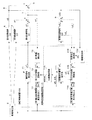
(6)第3実施形態の適応制御装置100の詳細構成
次に、第3実施形態の適応制御装置100の詳細構成について、図4を参照して説明する。ここで、第3実施形態の適応制御装置100は、残差目標値etargetnが適応的に設定される場合であって、残差目標値etargetnには振幅目標値aeを含むが、位相目標値φeを含まない場合である。
(6) Detailed Configuration of Adaptive Control Device 100 of Third Embodiment Next, a detailed configuration of the adaptive control device 100 of the third embodiment will be described with reference to FIG. Here, the adaptive control apparatus 100 of the third embodiment is a case where the residual target value etarget n is adaptively set, and the residual target value etarget n includes the amplitude target value a e , but the phase a case containing no target value phi e.
図4は、第3実施形態及び後述する第4実施形態の適応制御装置100のブロック図を示す。第3実施形態の適応制御装置100において、上述した第1実施形態の適応制御装置1と同一構成については同一符号を付して詳細な説明を省略する。つまり、第3実施形態の適応制御装置100は、第1実施形態の適応制御装置1に対して、観測点目標値設定部110のみが相違する。以下、観測点目標値設定部110のみについて説明する。 FIG. 4 shows a block diagram of the adaptive control apparatus 100 of the third embodiment and a fourth embodiment described later. In the adaptive control device 100 of the third embodiment, the same components as those of the adaptive control device 1 of the first embodiment described above are denoted by the same reference numerals, and detailed description thereof is omitted. That is, the adaptive control device 100 of the third embodiment is different from the adaptive control device 1 of the first embodiment only in the observation point target value setting unit 110. Only the observation point target value setting unit 110 will be described below.
観測点目標値設定部110は、残差目標値etargetnを適応的に設定する。この観測点目標値設定部110は、仮想適応信号発生部111と、振動検出部112と、仮想残差検出部113と、仮想伝達関数推定部114と、第2フィルタ係数更新部115と、更新目標値設定部116とから構成される。
The observation point target value setting unit 110 adaptively sets the residual target value etarget n . This observation point target value setting unit 110 includes a virtual adaptive
仮想適応信号発生部111は、振動発生源2から発生される周期性信号fの一次周波数成分の角振動数ωに基づき、式(62)に従って得られる仮想適応信号y2nを第2伝達経路5中に仮想的に発生させる。ここで、仮想適応信号y2nは、式(62)から明らかなように、第2振幅フィルタ係数a2n及び第2位相フィルタ係数φ2nを構成成分に含む一次正弦波からなる。そして、第2振幅フィルタ係数a2n及び第2位相フィルタ係数φ2nは、第2フィルタ係数更新部115により適応的に更新される。
The virtual adaptive
振動検出部112は、第2伝達経路5中の第2観測点8において周期性信号fに基づき生じる第2観測点振動d2を検出する。この第2観測点振動d2は、周期性信号fが第2伝達特性G2を介して伝達された振動である。
The
仮想残差検出部113は、仮想観測点9における仮想残差e2nを検出(算出)する。この仮想残差e2nは、式(63)に示すように、周期性信号fが第2伝達経路5を介して伝達される第2観測点振動d2に、仮想適応信号y2nが仮想伝達特性G2を介して仮想的に加えることにより生じる信号である。つまり、仮想残差検出部113は、仮想適応信号y2n及び第2観測点振動d2に基づき、仮想残差e2nを検出する。
The virtual
![]()
![]()
仮想伝達関数推定部114は、振動発生源2から発生される周期性信号fの一次周波数成分の角振動数ωに基づき、仮想伝達特性G2の伝達関数の推定値Gh2を算出する。この仮想伝達特性G2の伝達関数は、振幅成分と位相成分とが含まれている。つまり、仮想伝達関数推定部114は、仮想伝達特性G2の伝達関数の振幅成分の推定値Ah2と、位相成分の推定値Φh2とを算出する。例えば、仮想伝達関数推定部114は、予め、角振動数ωに応じたそれぞれの推定値Ah2、Φh2をマップなどとして記憶しておくようにしてもよい。この場合、実際に振動発生源2から発生された周期性信号fの角振動数ωと、記憶されているマップデータとにより、それぞれの推定値Ah2、Φh2を決定する。
The virtual transfer
第2フィルタ係数更新部115は、角振動数ω、仮想残差e2n及び仮想伝達関数推定値Gh2(Ah2、Φh2)に基づき、式(64)(65)に従って、第2振幅フィルタ係数a2n及び第2位相フィルタ係数φ2nを更新する。そして、第2フィルタ係数更新部115により更新された第2振幅フィルタ係数a2n及び第2位相フィルタ係数φ2nにより、仮想適応信号発生部111の適応信号y2nの第2振幅フィルタ係数a2n及び第2位相フィルタ係数φ2nを更新する。
Based on the angular frequency ω, the virtual residual e2 n, and the virtual transfer function estimated value Gh2 (Ah2, Φh2), the second filter
ここで、上述した第2振幅フィルタ係数a2n及び第1位相フィルタ係数φ2nの更新式(64)(65)の決定方法、第1実施形態における第1振幅フィルタ係数a1n及び第1位相フィルタ係数φ1nの更新式(54)(55)の決定方法と実質的に同一である。 Here, the determination method of the update equations (64) and (65) of the second amplitude filter coefficient a2 n and the first phase filter coefficient φ2 n described above, the first amplitude filter coefficient a1 n and the first phase filter in the first embodiment This is substantially the same as the method of determining the update equations (54) and (55) for the coefficient φ1 n .
更新目標値設定部116は、第2フィルタ係数更新部115により更新された第2振幅フィルタ係数a2nを式(66)に従って振幅目標値aeに設定する。さらに、更新目標値設定部116は、更新設定された振幅目標値aeを含む残差目標値etargetnを式(67)に従って設定する。そして、設定された残差目標値etargetnに従って、第1フィルタ係数更新部15の残差目標値etargetnが更新される。
Updating the target
以上のように構成することで、第1観測点7における残差e1nが残差目標値etargetnに一致するように収束させることができる。そして、残差目標値etargetnは、第2観測点振動に適応的に一致するようにしている。従って、対象評価点3においては、周期性信号fが第2伝達経路5を介して伝達された周期性信号成分d2に残差e1nが加えられた信号は、ゼロとなる。
By configuring as described above, the residual e1 n at the
(7)第3実施形態の第1変形態様
また、上記第3実施形態において、第2フィルタ係数更新部115における第2位相フィルタ係数φ2nの更新式(65)を下記の式(68)に置き換えてもよい。この更新式(68)は、上記第3実施形態における更新式(65)の仮想伝達特性の伝達関数の推定値の振幅成分Ah2及び第2振幅フィルタ係数a2nを消去した式である。
(7) First Modification of Third Embodiment In the third embodiment, the update equation (65) of the second phase filter coefficient φ2 n in the second filter
![]()
![]()
このように、第2位相フィルタ係数φ2nの更新式(68)を用いた場合には、更新式(65)を用いた場合に比べて、収束性はほとんど変わらない。そして、更新式(68)によれば、仮想伝達特性G2の伝達関数の推定値の振幅成分Ah2及び第2振幅フィルタ係数a2nを演算処理する必要がないため、演算負荷を低減することができる。このことは、演算処理能力の低いマイクロコンピュータを用いることができ、結果として低コスト化を図ることができる。 Thus, when the update formula (68) of the second phase filter coefficient φ2 n is used, the convergence is almost the same as when the update formula (65) is used. According to the update formula (68), it is not necessary to perform the arithmetic processing on the amplitude component Ah2 and the second amplitude filter coefficient a2 n of the estimated value of the transfer function of the virtual transfer characteristic G2, and thus the calculation load can be reduced. . For this reason, a microcomputer having a low processing capacity can be used, and as a result, the cost can be reduced.
(8)第4実施形態の適応制御装置100の詳細構成
次に、第4実施形態の適応制御装置100の詳細構成について説明する。ここで、第4実施形態の適応制御装置100は、残差目標値etargetnが適応的に設定される場合であって、残差目標値etargetnには振幅目標値ae及び位相目標値φeを含む場合である。この第4実施形態の適応制御装置100の構成は、上述した第3実施形態の適応制御装置100の構成と同一構成からなる。ただし、更新目標値設定部116が異なる。以下、第3実施形態と異なる点のみについて説明する。
(8) Detailed Configuration of Adaptive Control Device 100 of Fourth Embodiment Next, a detailed configuration of the adaptive control device 100 of the fourth embodiment will be described. Here, the adaptive control apparatus 100 of the fourth embodiment is a case where the residual target value etarget n is adaptively set, and the residual target value etarget n includes the amplitude target value a e and the phase target value φ. This is the case where e is included. The configuration of the adaptive control device 100 of the fourth embodiment is the same as the configuration of the adaptive control device 100 of the third embodiment described above. However, the update target
第4実施形態の更新目標値設定部116は、第2フィルタ係数更新部115により更新された第2振幅フィルタ係数a2n及び第2位相フィルタ係数φ2nを式(69)(70)に従って振幅目標値ae及び位相目標値φeに設定する。さらに、更新目標値設定部116は、更新設定された振幅目標値ae及び位相目標値φeを含む残差目標値etargetnを式(71)に従って設定する。そして、設定された残差目標値etargetnに従って、第1フィルタ係数更新部15の残差目標値etargetnが更新される。
The update target
以上のように構成することで、第1観測点7における残差e1nが残差目標値etargetnに一致するように収束させることができる。そして、残差目標値etargetnは、第2観測点振動に適応的に一致するようにしている。従って、仮に、図3に示したように、第1伝達経路4を介して伝達された周期性信号成分d1の位相と第2伝達経路5を介して伝達された周期性信号成分d2の位相とが異なるような場合であっても、対象評価点3においては、周期性信号fが第2伝達経路5を介して伝達された周期性信号成分d2に残差e1nが加えられた信号は、ゼロとすることができる。
By configuring as described above, the residual e1 n at the
1、100:周期性信号の適応制御装置、
3:対象評価点、 7:第1観測点、 8:第2観測点、 9:仮想観測点
1, 100: an adaptive control device for periodic signals,
3: Target evaluation point, 7: First observation point, 8: Second observation point, 9: Virtual observation point
Claims (9)
前記所定の伝達経路は、第1伝達経路及び前記第1伝達経路と異なる第2伝達経路を含み、
前記周期性信号のうち特定周波数成分の角振動数に基づき、第1振幅フィルタ係数及び第1位相フィルタ係数を構成成分に含む前記適応信号を前記第1伝達経路中に発生させる適応信号発生部と、
前記第1伝達経路中のうち前記適応信号発生部と前記対象評価点との間に位置する第1観測点において、前記周期性信号に対して前記適応信号を所定の第1伝達特性を介して加えることにより生じる第1の残差を検出する第1残差検出部と、
少なくとも前記角振動数に応じた振幅目標値を含む前記第1観測点の周期性の残差目標値であって、前記角振動数および前記第2伝達経路の伝達特性に基づき前記残差目標値を設定する観測点目標値設定部と、
前記角振動数、前記第1の残差及び前記残差目標値に基づき前記第1振幅フィルタ係数及び前記第1位相フィルタ係数を更新する第1フィルタ係数更新部と、
を備えることを特徴とする周期性信号の適応制御装置。 By adding an adaptive signal synchronized with the periodic signal to the periodic signal generated from the vibration source, the influence of the periodic signal on the target evaluation point via the predetermined transmission path is actively increased. An adaptive control device for periodic signals to be reduced,
The predetermined transmission path includes a first transmission path and a second transmission path different from the first transmission path,
An adaptive signal generating unit for generating the adaptive signal in the first transmission path including the first amplitude filter coefficient and the first phase filter coefficient as constituent components based on the angular frequency of the specific frequency component of the periodic signal; ,
In the first observation path located between the adaptive signal generation unit and the target evaluation point in the first transmission path, the adaptive signal is transmitted to the periodic signal via a predetermined first transmission characteristic. A first residual detection unit for detecting a first residual generated by adding,
A residual target value of periodicity of the first observation point including at least an amplitude target value corresponding to the angular frequency, and the residual target value based on the angular frequency and transfer characteristics of the second transmission path Observation point target value setting unit for setting
A first filter coefficient updating unit that updates the first amplitude filter coefficient and the first phase filter coefficient based on the angular frequency, the first residual, and the residual target value;
An adaptive control device for periodic signals, comprising:
前記適応信号発生部は、式(1)に従って得られる前記適応信号を前記第1伝達経路中に発生させ、
前記第1フィルタ係数更新部は、前記角振動数、前記第1の残差、前記第1伝達関数推定値、及び、前記残差目標値に基づき、式(2)(3)(4)又は式(5)(6)(7)に従って式(1)における前記第1振幅フィルタ係数及び前記第1位相フィルタ係数を更新する請求項1記載の周期性信号の適応制御装置。
The adaptive signal generation unit generates the adaptive signal obtained according to Equation (1) in the first transmission path,
Based on the angular frequency, the first residual, the first transfer function estimated value, and the residual target value, the first filter coefficient updating unit may perform the following equations (2), (3), (4), or 2. The adaptive control apparatus for a periodic signal according to claim 1, wherein the first amplitude filter coefficient and the first phase filter coefficient in the expression (1) are updated according to the expressions (5), (6), and (7).
前記適応信号発生部は、式(8)に従って得られる前記適応信号を前記第1伝達経路中に発生させ、
前記第1フィルタ係数更新部は、前記角振動数、前記第1の残差、前記第1伝達関数推定値、及び、前記残差目標値に基づき、式(9)(10)(11)又は式(12)(13)(14)に従って式(8)における前記第1振幅フィルタ係数及び前記第1位相フィルタ係数を更新する請求項2記載の周期性信号の適応制御装置。
The adaptive signal generation unit generates the adaptive signal obtained according to Equation (8) in the first transmission path,
Based on the angular frequency, the first residual, the first transfer function estimated value, and the residual target value, the first filter coefficient updating unit may perform the following equations (9), (10), (11), or The periodic signal adaptive control apparatus according to claim 2, wherein the first amplitude filter coefficient and the first phase filter coefficient in the expression (8) are updated according to the expressions (12), (13), and (14).
前記角振動数に基づき、第2振幅フィルタ係数及び第2位相フィルタ係数を構成成分に含む式(15)に従って得られる仮想適応信号を前記第2伝達経路中に仮想的に発生させる仮想適応信号発生部と、
前記第2伝達経路中の第2観測点において前記周期性信号に基づき生じる第2観測点振動を検出する振動検出部と、
前記仮想適応信号及び前記第2観測点振動に基づき、仮想観測点において前記周期性信号に対して前記仮想適応信号を所定の仮想伝達特性を介して仮想的に加えることにより生じる仮想残差を検出する仮想残差検出部と、
前記角振動数に基づき前記仮想伝達特性の伝達関数の推定値を算出する仮想伝達関数推定部と、
前記角振動数、前記仮想残差及び前記仮想伝達関数推定値に基づき、式(16)(17)又は式(18)(19)に従って式(15)における前記第2振幅フィルタ係数及び前記第2位相フィルタ係数を更新する第2フィルタ係数更新部と、
更新された前記第2振幅フィルタ係数を式(20)に従って前記振幅目標値に設定する更新目標値設定部と、
を備える請求項1〜4の何れか一項に記載の周期性信号の適応制御装置。
Based on the angular frequency, virtual adaptive signal generator that generates virtually virtual adaptive signal obtained according to Equation (15) including a second amplitude filter coefficients and the second phase filter coefficient components in said second transmission path And
A vibration detector for detecting a second observation point vibration generated based on the periodic signal at a second observation point in the second transmission path;
Based on the virtual adaptive signal and the second observation point vibration, a virtual residual generated by virtually adding the virtual adaptive signal to the periodic signal through a predetermined virtual transfer characteristic at the virtual observation point is detected. A virtual residual detector to
A virtual transfer function estimator that calculates an estimate of the transfer function of the virtual transfer characteristic based on the angular frequency;
Based on the angular frequency, the virtual residual, and the virtual transfer function estimated value, the second amplitude filter coefficient and the second in Formula (15) according to Formula (16) (17) or Formula (18) (19) A second filter coefficient updating unit for updating the phase filter coefficient;
An updated target value setting unit that sets the updated second amplitude filter coefficient to the amplitude target value according to the equation (20);
The adaptive control apparatus of the periodic signal as described in any one of Claims 1-4 provided with these .
前記角振動数に基づき、第2振幅フィルタ係数及び第2位相フィルタ係数を構成成分に含む式(21)に従って得られる仮想適応信号を前記第2伝達経路中に仮想的に発生させる仮想適応信号発生部と、
前記第2伝達経路中の第2観測点において前記周期性信号に基づき生じる第2観測点振動を検出する振動検出部と、
前記仮想適応信号及び前記第2観測点振動に基づき、仮想観測点において前記周期性信号に対して前記仮想適応信号を所定の仮想伝達特性を介して仮想的に加えることにより生じる仮想残差を検出する仮想残差検出部と、
前記角振動数に基づき前記仮想伝達特性の伝達関数の推定値を算出する仮想伝達関数推定部と、
前記角振動数、前記仮想残差及び前記仮想伝達関数推定値に基づき、式(22)(23)又は式(24)(25)に従って式(21)における前記第2振幅フィルタ係数及び前記第2位相フィルタ係数を更新する第2フィルタ係数更新部と、
更新された前記第2位相フィルタ係数を式(26)に従って前記位相目標値に設定する更新目標値設定部と、
を備える請求項7記載の周期性信号の適応制御装置。
Virtual adaptive signal generation for virtually generating in the second transmission path a virtual adaptive signal obtained according to the equation (21) including the second amplitude filter coefficient and the second phase filter coefficient as constituent components based on the angular frequency And
A vibration detector for detecting a second observation point vibration generated based on the periodic signal at a second observation point in the second transmission path;
Based on the virtual adaptive signal and the second observation point vibration, a virtual residual generated by virtually adding the virtual adaptive signal to the periodic signal through a predetermined virtual transfer characteristic at the virtual observation point is detected. A virtual residual detector to
A virtual transfer function estimator that calculates an estimate of the transfer function of the virtual transfer characteristic based on the angular frequency;
Based on the angular frequency, the virtual residual, and the virtual transfer function estimate, the second amplitude filter coefficient and the second in Equation (21) according to Equation (22) (23) or Equation (24) (25) A second filter coefficient updating unit for updating the phase filter coefficient;
An updated target value setting unit that sets the updated second phase filter coefficient to the phase target value according to Equation (26);
An adaptive control apparatus for a periodic signal according to claim 7 .
Priority Applications (3)
| Application Number | Priority Date | Filing Date | Title |
|---|---|---|---|
| JP2006054879A JP4792302B2 (en) | 2006-03-01 | 2006-03-01 | Adaptive controller for periodic signals |
| US11/680,100 US8139629B2 (en) | 2006-03-01 | 2007-02-28 | Adaptive controller |
| DE102007000119A DE102007000119A1 (en) | 2006-03-01 | 2007-02-28 | Adaptive control device |
Applications Claiming Priority (1)
| Application Number | Priority Date | Filing Date | Title |
|---|---|---|---|
| JP2006054879A JP4792302B2 (en) | 2006-03-01 | 2006-03-01 | Adaptive controller for periodic signals |
Publications (2)
| Publication Number | Publication Date |
|---|---|
| JP2007233057A JP2007233057A (en) | 2007-09-13 |
| JP4792302B2 true JP4792302B2 (en) | 2011-10-12 |
Family
ID=38460400
Family Applications (1)
| Application Number | Title | Priority Date | Filing Date |
|---|---|---|---|
| JP2006054879A Expired - Fee Related JP4792302B2 (en) | 2006-03-01 | 2006-03-01 | Adaptive controller for periodic signals |
Country Status (3)
| Country | Link |
|---|---|
| US (1) | US8139629B2 (en) |
| JP (1) | JP4792302B2 (en) |
| DE (1) | DE102007000119A1 (en) |
Families Citing this family (2)
| Publication number | Priority date | Publication date | Assignee | Title |
|---|---|---|---|---|
| WO2011065441A1 (en) * | 2009-11-25 | 2011-06-03 | シンフォニアテクノロジー株式会社 | Vibration damping device and vehicle provided therewith |
| CN114827813B (en) * | 2022-04-26 | 2025-07-11 | 歌尔股份有限公司 | Noise reduction method, headphone device and storage medium |
Family Cites Families (15)
| Publication number | Priority date | Publication date | Assignee | Title |
|---|---|---|---|---|
| US5124626A (en) * | 1990-12-20 | 1992-06-23 | Mts Systems Corporation | Sinusoidal signal amplitude and phase control for an adaptive feedback control system |
| US5245830A (en) * | 1992-06-03 | 1993-09-21 | Lockheed Missiles & Space Company, Inc. | Adaptive error correction control system for optimizing stirling refrigerator operation |
| JPH06138888A (en) * | 1992-10-26 | 1994-05-20 | Honda Motor Co Ltd | Active vibration control device |
| JP3406628B2 (en) * | 1992-12-25 | 2003-05-12 | アルパイン株式会社 | Noise cancellation method |
| DE69423531T2 (en) * | 1993-02-02 | 2000-07-20 | Honda Giken Kogyo K.K., Tokio/Tokyo | Vibration / noise reduction device |
| JP3430795B2 (en) * | 1996-05-27 | 2003-07-28 | 東海ゴム工業株式会社 | Adaptive control method for periodic signals |
| JP3451891B2 (en) * | 1997-06-13 | 2003-09-29 | 日産自動車株式会社 | Active vibration control device |
| JP2002005227A (en) * | 2000-06-19 | 2002-01-09 | Tokai Rubber Ind Ltd | Control data setting method and data recording medium for active mount control device |
| JP2003047260A (en) * | 2001-05-22 | 2003-02-14 | Aisin Seiki Co Ltd | Driving method of bridge circuit for driving inductance load |
| WO2004009007A1 (en) * | 2002-07-19 | 2004-01-29 | The Penn State Research Foundation | A linear independent method for noninvasive online secondary path modeling |
| JP2005155664A (en) * | 2003-11-20 | 2005-06-16 | Tokai Rubber Ind Ltd | Vibration control method and vibration control device for active vibration isolator |
| JP4858935B2 (en) * | 2004-02-10 | 2012-01-18 | 国立大学法人東京工業大学 | Nonlinear controller and nonlinear control method |
| JP4258845B2 (en) | 2004-04-20 | 2009-04-30 | 株式会社安川電機 | Adaptive controller |
| JP4213640B2 (en) * | 2004-07-28 | 2009-01-21 | パナソニック株式会社 | Active noise reduction device |
| US7751963B2 (en) * | 2008-02-14 | 2010-07-06 | Gm Global Technology Operations, Inc. | Self-tuning active engine mount for vehicles with active fuel management engine |
-
2006
- 2006-03-01 JP JP2006054879A patent/JP4792302B2/en not_active Expired - Fee Related
-
2007
- 2007-02-28 DE DE102007000119A patent/DE102007000119A1/en not_active Withdrawn
- 2007-02-28 US US11/680,100 patent/US8139629B2/en not_active Expired - Fee Related
Also Published As
| Publication number | Publication date |
|---|---|
| DE102007000119A1 (en) | 2007-10-04 |
| US20070206669A1 (en) | 2007-09-06 |
| JP2007233057A (en) | 2007-09-13 |
| US8139629B2 (en) | 2012-03-20 |
Similar Documents
| Publication | Publication Date | Title |
|---|---|---|
| EP2600341B1 (en) | Active vibration noise control apparatus | |
| JP5713958B2 (en) | Active noise control device | |
| US7340065B2 (en) | Active noise control system | |
| JP5757346B2 (en) | Active vibration noise control device | |
| US10276146B2 (en) | Active noise control device | |
| US20160344433A1 (en) | Auto-selection method for modeling secondary-path estimation filter for active noise control system | |
| JP6073454B2 (en) | Active vibration noise control device | |
| CN116438597A (en) | Systems and methods for adapting estimated secondary paths | |
| JP4792302B2 (en) | Adaptive controller for periodic signals | |
| JP4945425B2 (en) | Active anti-vibration adaptive control device | |
| JP2005257919A (en) | Image blurring correction device | |
| JP3611181B2 (en) | Adaptive control method for periodic signals | |
| JP5846776B2 (en) | Active vibration and noise suppression device | |
| JP4569514B2 (en) | Adaptive notch filter | |
| JP5090272B2 (en) | Active vibration noise control device | |
| JPH1049204A (en) | Adaptive control method for periodic signals | |
| JP5670301B2 (en) | Active vibration noise control device | |
| JP5674569B2 (en) | Active vibration and noise suppression device | |
| JP5141351B2 (en) | Active noise control device | |
| JPH1153004A (en) | Adaptive control method for periodic signals | |
| JP3389981B2 (en) | Adaptive control method for periodic signals | |
| JP3611168B2 (en) | Adaptive control method for periodic signals | |
| JP3611180B2 (en) | Adaptive control method for periodic signals | |
| JP3804496B2 (en) | Adaptive step size control adaptive filter and adaptive scale factor control method | |
| JP3568105B2 (en) | Adaptive control method for periodic signals |
Legal Events
| Date | Code | Title | Description |
|---|---|---|---|
| A621 | Written request for application examination |
Free format text: JAPANESE INTERMEDIATE CODE: A621 Effective date: 20080820 |
|
| A977 | Report on retrieval |
Free format text: JAPANESE INTERMEDIATE CODE: A971007 Effective date: 20110127 |
|
| A131 | Notification of reasons for refusal |
Free format text: JAPANESE INTERMEDIATE CODE: A131 Effective date: 20110322 |
|
| A521 | Request for written amendment filed |
Free format text: JAPANESE INTERMEDIATE CODE: A523 Effective date: 20110520 |
|
| TRDD | Decision of grant or rejection written | ||
| A01 | Written decision to grant a patent or to grant a registration (utility model) |
Free format text: JAPANESE INTERMEDIATE CODE: A01 Effective date: 20110712 |
|
| A01 | Written decision to grant a patent or to grant a registration (utility model) |
Free format text: JAPANESE INTERMEDIATE CODE: A01 |
|
| A61 | First payment of annual fees (during grant procedure) |
Free format text: JAPANESE INTERMEDIATE CODE: A61 Effective date: 20110725 |
|
| FPAY | Renewal fee payment (event date is renewal date of database) |
Free format text: PAYMENT UNTIL: 20140729 Year of fee payment: 3 |
|
| R150 | Certificate of patent or registration of utility model |
Ref document number: 4792302 Country of ref document: JP Free format text: JAPANESE INTERMEDIATE CODE: R150 Free format text: JAPANESE INTERMEDIATE CODE: R150 |
|
| LAPS | Cancellation because of no payment of annual fees |