JP4792155B2 - Composite ceramic article and manufacturing method thereof - Google Patents
Composite ceramic article and manufacturing method thereof Download PDFInfo
- Publication number
- JP4792155B2 JP4792155B2 JP2000262014A JP2000262014A JP4792155B2 JP 4792155 B2 JP4792155 B2 JP 4792155B2 JP 2000262014 A JP2000262014 A JP 2000262014A JP 2000262014 A JP2000262014 A JP 2000262014A JP 4792155 B2 JP4792155 B2 JP 4792155B2
- Authority
- JP
- Japan
- Prior art keywords
- ceramic
- powder
- gap
- scintillator
- green
- Prior art date
- Legal status (The legal status is an assumption and is not a legal conclusion. Google has not performed a legal analysis and makes no representation as to the accuracy of the status listed.)
- Expired - Fee Related
Links
- 239000000919 ceramic Substances 0.000 title claims description 128
- 238000004519 manufacturing process Methods 0.000 title claims description 13
- 239000002131 composite material Substances 0.000 title description 28
- 239000000463 material Substances 0.000 claims description 67
- 239000000843 powder Substances 0.000 claims description 58
- 238000000034 method Methods 0.000 claims description 48
- 238000010304 firing Methods 0.000 claims description 30
- 239000002002 slurry Substances 0.000 claims description 25
- 239000000203 mixture Substances 0.000 claims description 24
- 239000011230 binding agent Substances 0.000 claims description 17
- 238000011049 filling Methods 0.000 claims description 17
- CMIHHWBVHJVIGI-UHFFFAOYSA-N gadolinium(iii) oxide Chemical compound [O-2].[O-2].[O-2].[Gd+3].[Gd+3] CMIHHWBVHJVIGI-UHFFFAOYSA-N 0.000 claims description 16
- 229910010293 ceramic material Inorganic materials 0.000 claims description 15
- 239000002245 particle Substances 0.000 claims description 10
- 239000000126 substance Substances 0.000 claims description 10
- 239000011248 coating agent Substances 0.000 claims description 9
- 238000000576 coating method Methods 0.000 claims description 9
- 239000002223 garnet Substances 0.000 claims description 9
- 239000011888 foil Substances 0.000 claims description 8
- 229910052751 metal Inorganic materials 0.000 claims description 8
- 239000002184 metal Substances 0.000 claims description 8
- 238000012856 packing Methods 0.000 claims description 8
- SIWVEOZUMHYXCS-UHFFFAOYSA-N oxo(oxoyttriooxy)yttrium Chemical compound O=[Y]O[Y]=O SIWVEOZUMHYXCS-UHFFFAOYSA-N 0.000 claims description 6
- RUDFQVOCFDJEEF-UHFFFAOYSA-N yttrium(III) oxide Inorganic materials [O-2].[O-2].[O-2].[Y+3].[Y+3] RUDFQVOCFDJEEF-UHFFFAOYSA-N 0.000 claims description 5
- 238000005507 spraying Methods 0.000 claims description 4
- 229910001938 gadolinium oxide Inorganic materials 0.000 claims 3
- 229940075613 gadolinium oxide Drugs 0.000 claims 3
- 239000000243 solution Substances 0.000 description 29
- VEXZGXHMUGYJMC-UHFFFAOYSA-N Hydrochloric acid Chemical compound Cl VEXZGXHMUGYJMC-UHFFFAOYSA-N 0.000 description 18
- 238000002591 computed tomography Methods 0.000 description 14
- 239000002244 precipitate Substances 0.000 description 14
- 238000001746 injection moulding Methods 0.000 description 11
- MUBZPKHOEPUJKR-UHFFFAOYSA-N Oxalic acid Chemical compound OC(=O)C(O)=O MUBZPKHOEPUJKR-UHFFFAOYSA-N 0.000 description 10
- 239000007788 liquid Substances 0.000 description 10
- 239000002994 raw material Substances 0.000 description 10
- VBIXEXWLHSRNKB-UHFFFAOYSA-N ammonium oxalate Chemical compound [NH4+].[NH4+].[O-]C(=O)C([O-])=O VBIXEXWLHSRNKB-UHFFFAOYSA-N 0.000 description 9
- 150000001768 cations Chemical class 0.000 description 9
- 238000010438 heat treatment Methods 0.000 description 9
- 238000002844 melting Methods 0.000 description 9
- 230000008018 melting Effects 0.000 description 9
- 238000001556 precipitation Methods 0.000 description 9
- 230000008569 process Effects 0.000 description 8
- 230000005855 radiation Effects 0.000 description 7
- XLYOFNOQVPJJNP-UHFFFAOYSA-N water Substances O XLYOFNOQVPJJNP-UHFFFAOYSA-N 0.000 description 7
- 229910002651 NO3 Inorganic materials 0.000 description 6
- NHNBFGGVMKEFGY-UHFFFAOYSA-N Nitrate Chemical compound [O-][N+]([O-])=O NHNBFGGVMKEFGY-UHFFFAOYSA-N 0.000 description 6
- -1 gadolinium scandium aluminum Chemical compound 0.000 description 6
- 238000001228 spectrum Methods 0.000 description 6
- 238000002156 mixing Methods 0.000 description 5
- 239000012188 paraffin wax Substances 0.000 description 5
- 235000019809 paraffin wax Nutrition 0.000 description 5
- 235000019271 petrolatum Nutrition 0.000 description 5
- VEXZGXHMUGYJMC-UHFFFAOYSA-M Chloride anion Chemical compound [Cl-] VEXZGXHMUGYJMC-UHFFFAOYSA-M 0.000 description 4
- LFQSCWFLJHTTHZ-UHFFFAOYSA-N Ethanol Chemical compound CCO LFQSCWFLJHTTHZ-UHFFFAOYSA-N 0.000 description 4
- 238000010586 diagram Methods 0.000 description 4
- 238000000227 grinding Methods 0.000 description 4
- 238000012545 processing Methods 0.000 description 4
- 229910052693 Europium Inorganic materials 0.000 description 3
- KFZMGEQAYNKOFK-UHFFFAOYSA-N Isopropanol Chemical compound CC(C)O KFZMGEQAYNKOFK-UHFFFAOYSA-N 0.000 description 3
- OKKJLVBELUTLKV-UHFFFAOYSA-N Methanol Chemical compound OC OKKJLVBELUTLKV-UHFFFAOYSA-N 0.000 description 3
- GRYLNZFGIOXLOG-UHFFFAOYSA-N Nitric acid Chemical compound O[N+]([O-])=O GRYLNZFGIOXLOG-UHFFFAOYSA-N 0.000 description 3
- 239000012190 activator Substances 0.000 description 3
- 230000005540 biological transmission Effects 0.000 description 3
- 230000000052 comparative effect Effects 0.000 description 3
- 238000009826 distribution Methods 0.000 description 3
- 238000000465 moulding Methods 0.000 description 3
- 229910017604 nitric acid Inorganic materials 0.000 description 3
- 239000011148 porous material Substances 0.000 description 3
- 238000003825 pressing Methods 0.000 description 3
- 239000007787 solid Substances 0.000 description 3
- 125000006850 spacer group Chemical group 0.000 description 3
- WRIDQFICGBMAFQ-UHFFFAOYSA-N (E)-8-Octadecenoic acid Natural products CCCCCCCCCC=CCCCCCCC(O)=O WRIDQFICGBMAFQ-UHFFFAOYSA-N 0.000 description 2
- LQJBNNIYVWPHFW-UHFFFAOYSA-N 20:1omega9c fatty acid Natural products CCCCCCCCCCC=CCCCCCCCC(O)=O LQJBNNIYVWPHFW-UHFFFAOYSA-N 0.000 description 2
- QSBYPNXLFMSGKH-UHFFFAOYSA-N 9-Heptadecensaeure Natural products CCCCCCCC=CCCCCCCCC(O)=O QSBYPNXLFMSGKH-UHFFFAOYSA-N 0.000 description 2
- QGZKDVFQNNGYKY-UHFFFAOYSA-N Ammonia Chemical compound N QGZKDVFQNNGYKY-UHFFFAOYSA-N 0.000 description 2
- NLXLAEXVIDQMFP-UHFFFAOYSA-N Ammonia chloride Chemical compound [NH4+].[Cl-] NLXLAEXVIDQMFP-UHFFFAOYSA-N 0.000 description 2
- OKTJSMMVPCPJKN-UHFFFAOYSA-N Carbon Chemical compound [C] OKTJSMMVPCPJKN-UHFFFAOYSA-N 0.000 description 2
- IMNFDUFMRHMDMM-UHFFFAOYSA-N N-Heptane Chemical compound CCCCCCC IMNFDUFMRHMDMM-UHFFFAOYSA-N 0.000 description 2
- 229910052779 Neodymium Inorganic materials 0.000 description 2
- ZQPPMHVWECSIRJ-UHFFFAOYSA-N Oleic acid Natural products CCCCCCCCC=CCCCCCCCC(O)=O ZQPPMHVWECSIRJ-UHFFFAOYSA-N 0.000 description 2
- 239000005642 Oleic acid Substances 0.000 description 2
- 235000021355 Stearic acid Nutrition 0.000 description 2
- MCMNRKCIXSYSNV-UHFFFAOYSA-N Zirconium dioxide Chemical compound O=[Zr]=O MCMNRKCIXSYSNV-UHFFFAOYSA-N 0.000 description 2
- 230000008901 benefit Effects 0.000 description 2
- 229910052799 carbon Inorganic materials 0.000 description 2
- 239000003795 chemical substances by application Substances 0.000 description 2
- 150000001875 compounds Chemical class 0.000 description 2
- 238000007796 conventional method Methods 0.000 description 2
- 239000008367 deionised water Substances 0.000 description 2
- 229910021641 deionized water Inorganic materials 0.000 description 2
- 239000002270 dispersing agent Substances 0.000 description 2
- OGPBJKLSAFTDLK-UHFFFAOYSA-N europium atom Chemical compound [Eu] OGPBJKLSAFTDLK-UHFFFAOYSA-N 0.000 description 2
- AEBZCFFCDTZXHP-UHFFFAOYSA-N europium(3+);oxygen(2-) Chemical compound [O-2].[O-2].[O-2].[Eu+3].[Eu+3] AEBZCFFCDTZXHP-UHFFFAOYSA-N 0.000 description 2
- 238000001914 filtration Methods 0.000 description 2
- 238000003384 imaging method Methods 0.000 description 2
- 150000002500 ions Chemical class 0.000 description 2
- QXJSBBXBKPUZAA-UHFFFAOYSA-N isooleic acid Natural products CCCCCCCC=CCCCCCCCCC(O)=O QXJSBBXBKPUZAA-UHFFFAOYSA-N 0.000 description 2
- QEFYFXOXNSNQGX-UHFFFAOYSA-N neodymium atom Chemical compound [Nd] QEFYFXOXNSNQGX-UHFFFAOYSA-N 0.000 description 2
- QIQXTHQIDYTFRH-UHFFFAOYSA-N octadecanoic acid Chemical compound CCCCCCCCCCCCCCCCCC(O)=O QIQXTHQIDYTFRH-UHFFFAOYSA-N 0.000 description 2
- OQCDKBAXFALNLD-UHFFFAOYSA-N octadecanoic acid Natural products CCCCCCCC(C)CCCCCCCCC(O)=O OQCDKBAXFALNLD-UHFFFAOYSA-N 0.000 description 2
- ZQPPMHVWECSIRJ-KTKRTIGZSA-N oleic acid Chemical compound CCCCCCCC\C=C/CCCCCCCC(O)=O ZQPPMHVWECSIRJ-KTKRTIGZSA-N 0.000 description 2
- 230000003287 optical effect Effects 0.000 description 2
- 235000006408 oxalic acid Nutrition 0.000 description 2
- 239000003973 paint Substances 0.000 description 2
- 239000000047 product Substances 0.000 description 2
- 229910001404 rare earth metal oxide Inorganic materials 0.000 description 2
- 238000002310 reflectometry Methods 0.000 description 2
- 239000008117 stearic acid Substances 0.000 description 2
- 239000000725 suspension Substances 0.000 description 2
- 238000005406 washing Methods 0.000 description 2
- 241001279686 Allium moly Species 0.000 description 1
- BVKZGUZCCUSVTD-UHFFFAOYSA-L Carbonate Chemical compound [O-]C([O-])=O BVKZGUZCCUSVTD-UHFFFAOYSA-L 0.000 description 1
- 229910052684 Cerium Inorganic materials 0.000 description 1
- VYZAMTAEIAYCRO-UHFFFAOYSA-N Chromium Chemical compound [Cr] VYZAMTAEIAYCRO-UHFFFAOYSA-N 0.000 description 1
- GYHNNYVSQQEPJS-UHFFFAOYSA-N Gallium Chemical compound [Ga] GYHNNYVSQQEPJS-UHFFFAOYSA-N 0.000 description 1
- ZOKXTWBITQBERF-UHFFFAOYSA-N Molybdenum Chemical compound [Mo] ZOKXTWBITQBERF-UHFFFAOYSA-N 0.000 description 1
- OAICVXFJPJFONN-UHFFFAOYSA-N Phosphorus Chemical compound [P] OAICVXFJPJFONN-UHFFFAOYSA-N 0.000 description 1
- 239000004743 Polypropylene Substances 0.000 description 1
- VYPSYNLAJGMNEJ-UHFFFAOYSA-N Silicium dioxide Chemical compound O=[Si]=O VYPSYNLAJGMNEJ-UHFFFAOYSA-N 0.000 description 1
- BQCADISMDOOEFD-UHFFFAOYSA-N Silver Chemical compound [Ag] BQCADISMDOOEFD-UHFFFAOYSA-N 0.000 description 1
- RTAQQCXQSZGOHL-UHFFFAOYSA-N Titanium Chemical compound [Ti] RTAQQCXQSZGOHL-UHFFFAOYSA-N 0.000 description 1
- TVFHPXMGPBXBAE-UHFFFAOYSA-N [Sc].[Gd] Chemical compound [Sc].[Gd] TVFHPXMGPBXBAE-UHFFFAOYSA-N 0.000 description 1
- 238000002835 absorbance Methods 0.000 description 1
- 238000010521 absorption reaction Methods 0.000 description 1
- 150000003926 acrylamides Chemical class 0.000 description 1
- 150000001252 acrylic acid derivatives Chemical class 0.000 description 1
- NIXOWILDQLNWCW-UHFFFAOYSA-N acrylic acid group Chemical group C(C=C)(=O)O NIXOWILDQLNWCW-UHFFFAOYSA-N 0.000 description 1
- 229910000310 actinide oxide Inorganic materials 0.000 description 1
- 230000004913 activation Effects 0.000 description 1
- 239000000443 aerosol Substances 0.000 description 1
- 150000001298 alcohols Chemical class 0.000 description 1
- 150000001336 alkenes Chemical class 0.000 description 1
- CEGOLXSVJUTHNZ-UHFFFAOYSA-K aluminium tristearate Chemical compound [Al+3].CCCCCCCCCCCCCCCCCC([O-])=O.CCCCCCCCCCCCCCCCCC([O-])=O.CCCCCCCCCCCCCCCCCC([O-])=O CEGOLXSVJUTHNZ-UHFFFAOYSA-K 0.000 description 1
- 229940063655 aluminum stearate Drugs 0.000 description 1
- JNDMLEXHDPKVFC-UHFFFAOYSA-N aluminum;oxygen(2-);yttrium(3+) Chemical compound [O-2].[O-2].[O-2].[Al+3].[Y+3] JNDMLEXHDPKVFC-UHFFFAOYSA-N 0.000 description 1
- 229910021529 ammonia Inorganic materials 0.000 description 1
- 235000019270 ammonium chloride Nutrition 0.000 description 1
- 239000012298 atmosphere Substances 0.000 description 1
- JRPBQTZRNDNNOP-UHFFFAOYSA-N barium titanate Chemical compound [Ba+2].[Ba+2].[O-][Ti]([O-])([O-])[O-] JRPBQTZRNDNNOP-UHFFFAOYSA-N 0.000 description 1
- 229910002113 barium titanate Inorganic materials 0.000 description 1
- 230000004888 barrier function Effects 0.000 description 1
- 235000013871 bee wax Nutrition 0.000 description 1
- 239000012166 beeswax Substances 0.000 description 1
- 230000015572 biosynthetic process Effects 0.000 description 1
- 238000001354 calcination Methods 0.000 description 1
- 150000004649 carbonic acid derivatives Chemical class 0.000 description 1
- 238000005266 casting Methods 0.000 description 1
- 238000005119 centrifugation Methods 0.000 description 1
- 239000007765 cera alba Substances 0.000 description 1
- ZMIGMASIKSOYAM-UHFFFAOYSA-N cerium Chemical compound [Ce][Ce][Ce][Ce][Ce][Ce][Ce][Ce][Ce][Ce][Ce][Ce][Ce][Ce][Ce][Ce][Ce][Ce][Ce][Ce][Ce][Ce][Ce][Ce][Ce][Ce][Ce][Ce][Ce][Ce][Ce][Ce][Ce][Ce][Ce][Ce][Ce][Ce] ZMIGMASIKSOYAM-UHFFFAOYSA-N 0.000 description 1
- 230000008859 change Effects 0.000 description 1
- 239000007795 chemical reaction product Substances 0.000 description 1
- 239000003153 chemical reaction reagent Substances 0.000 description 1
- 239000003638 chemical reducing agent Substances 0.000 description 1
- 229910052804 chromium Inorganic materials 0.000 description 1
- 239000011651 chromium Substances 0.000 description 1
- 239000004020 conductor Substances 0.000 description 1
- 238000004320 controlled atmosphere Methods 0.000 description 1
- 238000001816 cooling Methods 0.000 description 1
- 229920001577 copolymer Polymers 0.000 description 1
- 238000013480 data collection Methods 0.000 description 1
- 229910003460 diamond Inorganic materials 0.000 description 1
- 239000010432 diamond Substances 0.000 description 1
- 239000006185 dispersion Substances 0.000 description 1
- 238000009837 dry grinding Methods 0.000 description 1
- 239000000839 emulsion Substances 0.000 description 1
- 230000005284 excitation Effects 0.000 description 1
- 238000001125 extrusion Methods 0.000 description 1
- 239000012530 fluid Substances 0.000 description 1
- 229910052733 gallium Inorganic materials 0.000 description 1
- ZPDRQAVGXHVGTB-UHFFFAOYSA-N gallium;gadolinium(3+);oxygen(2-) Chemical compound [O-2].[O-2].[O-2].[Ga+3].[Gd+3] ZPDRQAVGXHVGTB-UHFFFAOYSA-N 0.000 description 1
- 229910000449 hafnium oxide Inorganic materials 0.000 description 1
- WIHZLLGSGQNAGK-UHFFFAOYSA-N hafnium(4+);oxygen(2-) Chemical compound [O-2].[O-2].[Hf+4] WIHZLLGSGQNAGK-UHFFFAOYSA-N 0.000 description 1
- 229910003439 heavy metal oxide Inorganic materials 0.000 description 1
- 238000005286 illumination Methods 0.000 description 1
- 238000002347 injection Methods 0.000 description 1
- 239000007924 injection Substances 0.000 description 1
- 230000003993 interaction Effects 0.000 description 1
- 238000010902 jet-milling Methods 0.000 description 1
- 229910000311 lanthanide oxide Inorganic materials 0.000 description 1
- 238000012886 linear function Methods 0.000 description 1
- 239000000314 lubricant Substances 0.000 description 1
- 238000003754 machining Methods 0.000 description 1
- 238000003760 magnetic stirring Methods 0.000 description 1
- 239000011159 matrix material Substances 0.000 description 1
- 238000003801 milling Methods 0.000 description 1
- 229910052750 molybdenum Inorganic materials 0.000 description 1
- 239000011733 molybdenum Substances 0.000 description 1
- 239000004570 mortar (masonry) Substances 0.000 description 1
- 150000002823 nitrates Chemical class 0.000 description 1
- 239000003960 organic solvent Substances 0.000 description 1
- 238000000643 oven drying Methods 0.000 description 1
- 150000003891 oxalate salts Chemical class 0.000 description 1
- 230000001590 oxidative effect Effects 0.000 description 1
- MMKQUGHLEMYQSG-UHFFFAOYSA-N oxygen(2-);praseodymium(3+) Chemical compound [O-2].[O-2].[O-2].[Pr+3].[Pr+3] MMKQUGHLEMYQSG-UHFFFAOYSA-N 0.000 description 1
- BPUBBGLMJRNUCC-UHFFFAOYSA-N oxygen(2-);tantalum(5+) Chemical compound [O-2].[O-2].[O-2].[O-2].[O-2].[Ta+5].[Ta+5] BPUBBGLMJRNUCC-UHFFFAOYSA-N 0.000 description 1
- RVTZCBVAJQQJTK-UHFFFAOYSA-N oxygen(2-);zirconium(4+) Chemical compound [O-2].[O-2].[Zr+4] RVTZCBVAJQQJTK-UHFFFAOYSA-N 0.000 description 1
- 230000035515 penetration Effects 0.000 description 1
- 238000005424 photoluminescence Methods 0.000 description 1
- 238000005498 polishing Methods 0.000 description 1
- 229920000642 polymer Polymers 0.000 description 1
- 239000005518 polymer electrolyte Substances 0.000 description 1
- 229920001155 polypropylene Polymers 0.000 description 1
- 229910003447 praseodymium oxide Inorganic materials 0.000 description 1
- 230000001902 propagating effect Effects 0.000 description 1
- 229910052761 rare earth metal Inorganic materials 0.000 description 1
- 150000002910 rare earth metals Chemical class 0.000 description 1
- 230000004044 response Effects 0.000 description 1
- 150000004760 silicates Chemical class 0.000 description 1
- 229910052709 silver Inorganic materials 0.000 description 1
- 239000004332 silver Substances 0.000 description 1
- 238000007569 slipcasting Methods 0.000 description 1
- 238000003756 stirring Methods 0.000 description 1
- 150000005846 sugar alcohols Polymers 0.000 description 1
- 229910001936 tantalum oxide Inorganic materials 0.000 description 1
- 229910003451 terbium oxide Inorganic materials 0.000 description 1
- SCRZPWWVSXWCMC-UHFFFAOYSA-N terbium(iii) oxide Chemical compound [O-2].[O-2].[O-2].[Tb+3].[Tb+3] SCRZPWWVSXWCMC-UHFFFAOYSA-N 0.000 description 1
- 239000012780 transparent material Substances 0.000 description 1
- WFKWXMTUELFFGS-UHFFFAOYSA-N tungsten Chemical compound [W] WFKWXMTUELFFGS-UHFFFAOYSA-N 0.000 description 1
- 229910052721 tungsten Inorganic materials 0.000 description 1
- 239000010937 tungsten Substances 0.000 description 1
- 238000001291 vacuum drying Methods 0.000 description 1
- 239000001993 wax Substances 0.000 description 1
- 239000000080 wetting agent Substances 0.000 description 1
- 229910019901 yttrium aluminum garnet Inorganic materials 0.000 description 1
- 229910001928 zirconium oxide Inorganic materials 0.000 description 1
Images
Classifications
-
- B—PERFORMING OPERATIONS; TRANSPORTING
- B28—WORKING CEMENT, CLAY, OR STONE
- B28B—SHAPING CLAY OR OTHER CERAMIC COMPOSITIONS; SHAPING SLAG; SHAPING MIXTURES CONTAINING CEMENTITIOUS MATERIAL, e.g. PLASTER
- B28B1/00—Producing shaped prefabricated articles from the material
- B28B1/24—Producing shaped prefabricated articles from the material by injection moulding
-
- B—PERFORMING OPERATIONS; TRANSPORTING
- B28—WORKING CEMENT, CLAY, OR STONE
- B28B—SHAPING CLAY OR OTHER CERAMIC COMPOSITIONS; SHAPING SLAG; SHAPING MIXTURES CONTAINING CEMENTITIOUS MATERIAL, e.g. PLASTER
- B28B1/00—Producing shaped prefabricated articles from the material
- B28B1/008—Producing shaped prefabricated articles from the material made from two or more materials having different characteristics or properties
-
- C—CHEMISTRY; METALLURGY
- C04—CEMENTS; CONCRETE; ARTIFICIAL STONE; CERAMICS; REFRACTORIES
- C04B—LIME, MAGNESIA; SLAG; CEMENTS; COMPOSITIONS THEREOF, e.g. MORTARS, CONCRETE OR LIKE BUILDING MATERIALS; ARTIFICIAL STONE; CERAMICS; REFRACTORIES; TREATMENT OF NATURAL STONE
- C04B35/00—Shaped ceramic products characterised by their composition; Ceramics compositions; Processing powders of inorganic compounds preparatory to the manufacturing of ceramic products
- C04B35/50—Shaped ceramic products characterised by their composition; Ceramics compositions; Processing powders of inorganic compounds preparatory to the manufacturing of ceramic products based on rare-earth compounds
-
- C—CHEMISTRY; METALLURGY
- C09—DYES; PAINTS; POLISHES; NATURAL RESINS; ADHESIVES; COMPOSITIONS NOT OTHERWISE PROVIDED FOR; APPLICATIONS OF MATERIALS NOT OTHERWISE PROVIDED FOR
- C09K—MATERIALS FOR MISCELLANEOUS APPLICATIONS, NOT PROVIDED FOR ELSEWHERE
- C09K11/00—Luminescent, e.g. electroluminescent, chemiluminescent materials
- C09K11/08—Luminescent, e.g. electroluminescent, chemiluminescent materials containing inorganic luminescent materials
- C09K11/77—Luminescent, e.g. electroluminescent, chemiluminescent materials containing inorganic luminescent materials containing rare earth metals
- C09K11/7766—Luminescent, e.g. electroluminescent, chemiluminescent materials containing inorganic luminescent materials containing rare earth metals containing two or more rare earth metals
- C09K11/7767—Chalcogenides
- C09K11/7769—Oxides
Landscapes
- Engineering & Computer Science (AREA)
- Chemical & Material Sciences (AREA)
- Ceramic Engineering (AREA)
- Manufacturing & Machinery (AREA)
- Materials Engineering (AREA)
- Organic Chemistry (AREA)
- Mechanical Engineering (AREA)
- Inorganic Chemistry (AREA)
- Structural Engineering (AREA)
- Measurement Of Radiation (AREA)
- Luminescent Compositions (AREA)
Description
【0001】
【発明の属する技術分野】
本発明は、広義にはセラミックに関するものであり、さらに具体的には、第一のセラミック物質と第二の物質とを同時に焼成して得られる発光性セラミック物質と介在反射性物質とからなる複合物品に関する。
【0002】
【従来の技術】
発光性物質は、電磁スペクトルのある部分におけるエネルギーを吸収して、電磁スペクトルの異なる部分におけるエネルギーを放出する。「蛍光体」又は「シンチレーター」とも呼ばれる大半の発光性物質は、電磁スペクトルの可視域外の放射線の吸収に応答して電磁スペクトルの可視域内の放射線を放出する。大半の蛍光体が応答する電磁スペクトル部分は、スペクトルの可視域よりも高エネルギー側である。例えば、(蛍光灯などでの)紫外線に応答する蛍光体、(ブラウン管などでの)電子に応答する蛍光体、及び(X線撮影法などでの)X線に応答する蛍光体などがある。
【0003】
発光性物質を用いた用途の一例はコンピュータ断層撮影(CT)スキャナである。CTスキャナでは、X線源とX線検出器列を被検体の両側に配置して、互いの位置関係を固定した状態で被検体の回りを回転させる。通例、CTスキャナは固体シンチレーターを含んでおり、これは透明な固体の形態にある発光性物質からなる。CTスキャナの典型的な検出器列は個々のシンチレーターバーを複数並べたものを含んでおり、各シンチレーターバーにはその蛍光を対応する電気信号へと変換する光検出器ダイオードが結合している。セルのシンチレーターはそのセルに入射したX線を吸収して発光し、該セルの光検出器で集光する。データの収集時、検出器列の各セルは、その列の当該セルのその時点での光強度を示す出力信号を与える。通例、CTスキャナ内の発光性物質は線形特性を有していてその光出力は吸収放射線量の線形関数であり、その光出力を励起放射線強度と直接関係づけることができる。CTスキャナの技術分野で周知のように出力信号を処理して被検体の像を作る。
【0004】
光検出器ダイオードの位置する面以外のシンチレーターバーの面に反射コーティングを設けるのが一般に有利である。コーティングは列の個々のシンチレーターバーで生じた光を反射する。コーティングの反射特性は、光が1つのシンチレーターバーから他のシンチレーターバーに伝わる(一般に「クロストーク」と呼ばれる)のを阻止することにより、像の精度を改善する。
【0005】
反射層で隔てられた多数のシンチレーターバーからなる検出器列の様々な形成方法が当技術分野で公知である。通例、シンチレーター材料の製造は、適当なセラミック粉体を調製し、粉体を粉砕し、粉体をプレスしてウェハを形成することによって行われる。次にウェハを焼成して通例は理論密度の99%を超える密度にする。
【0006】
従来の形成法で起こることが知られている一つつの問題は、焼成段階でウェハに反りが生じることである。かかる反りは、シンチレーター材料での不均一な密度分布によって収縮率に差が生じるためである。用途によってはシンチレーターバーの寸法公差が極めて小さく、例えば0.0013cm(0.0005インチ)未満のこともあるので、シンチレーターバー焼成時の収縮差のため、さらに加工しなければバーの最終寸法を達成するのが極めて困難になることがある。そこで、シンチレーターウェハは焼成後所望寸法まで研削、ラッピング及び研磨するのが通例であるが、これは費用と時間がかかることになる。シンチレーターバーの表面に反射コーティングを設けるプロセスも、多数の処理段階を必要とするので、費用がかさむことになりかねない。
【0007】
検出器列の他の形成方法が知られている。例えば、ドイツ特許出願公開第19709690A1号には、高密度層と高多孔質層とを交互に含んだ層構造をもつセラミック素子が開示されている。多孔質層は隣り合った高密度層間にブリッジを形成する超小型構造体を含んでいる。しかし、この方法ではシンチレーター素子同士がブリッジで光学的に結合した検出器列が得られるが、これはクロストークを起こすことになり、デバイスの画像精度を低下させる。
【0008】
ドイツ特許出願公開第19709691A1号には、スペーサ構造体を備えた未焼成セラミック素子を積み重ねて焼成した構造化セラミック素子の製造法が開示されている。未焼成セラミック素子を焼成した後スペーサ構造体間のキャビティーに機能補助物質を添加することができる。しかし、この場合も、スペーサ素子はセラミック素子と光学的に結合しており、そのためデバイスの画像精度が低下する。
【0009】
【発明が解決しようとする課題】
そこで、公知の方法でみられる問題を回避しながら、シンチレーターバー間に反射層が介在した検出器列を容易かつ有効に形成する方法を開発することが望まれる。
【0010】
【課題を解決するための手段】
本発明の一実施形態では、複合物品の製造方法は、互いに隙間ができるように間隔をおいて並んだ複数の未焼成セラミック素子を形成する段階、上記隙間を第二の物質で充填する段階、及び第二の物質と共に未焼成セラミック素子を焼成して複合物品を形成する段階を含んでなる。第二の物質は、焼成後、焼成セラミック素子内の実質的にすべての光が隣接する焼成セラミック素子に到達するのを防ぐ反射層として機能する。これら複数の未焼成セラミック素子は射出成形で形成することができ、各々が共通の連結部材から延在するものであってもよい。
【0011】
隙間を充填する段階は、第二の物質を粉体として含んだスラリーを形成し、スラリーに未焼成セラミック素子を浸漬することによって実施し得る。この隙間を充填する段階は、粉体形態の第二の物質を隙間に噴霧することによっても実施し得る。隙間を充填する第二の物質は未焼成セラミック素子の形成に用いたものと同一物質であってもよいが、例えば充填密度及び/又は粒度などが異なる。
【0012】
未焼成セラミック素子を反射体組成物と共に焼成するプロセスは、焼成時の寸法制御を改善するとともに、加工コストを低減する。
【0013】
【発明の実施の形態】
本発明の他の特徴及び利点は以下の詳細な説明並びに添付の図面から明らかとなろう。
【0014】
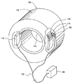
図1は、コンピュータ断層撮影(CT)スキャニングシステムの一例を示す。CTスキャニングシステム100は円筒形エンクロージャ110を有しており、その中に走査しようとする患者又は対象物が置かれる。ガントリー112がシリンダー110を囲繞していて、シリンダー軸の回りを回転するように構成されている。ガントリー112は、ガントリー上の電子機器をシステムの残りに接続するため、用いるシステムに応じて、完全に一回転した後戻るようにも設計し得るし、或いは連続回転するようにも設計し得る。ガントリー上の電子機器はX線源114を含んでいるが、X線源は通例扇形X線ビームを発生し、シリンダー110のガントリーの反対側に計装されたシンチレーター検出器列116に入射する。X線源の扇形パターンはX線源と検出器列116とで画成される平面内に位置する。
【0015】
シンチレーター検出器列116の各セル118にはシンチレーター材料からなる固体透明バーとシンチレーターバーに光学的に結合した光検出器ダイオードとが組み込まれている。各光検出器ダイオードの出力はガントリー上に計装された演算増幅器に接続される。各演算増幅器の出力は、個々の導線120又は他の電子機器によってコンピュータ断層撮影システムの主制御系150に接続される。図示した実施形態では、X線源の電力とシンチレーション検出器列の信号とがケーブル130によって主制御系150へと伝えられる。別法として、ガントリーの連続回転が望まれる場合には、スリップリング又は光もしくは無線伝送を用いてガントリー電子機器を主制御系150に接続してもよい。このタイプのCTスキャニングシステムでは、シンチレーター材料を用いて入射X線を光へと変換し、光を光検出器ダイオードで検出して電気信号へと変換し、電気信号を画像形成その他の目的に処理すればよい。
【0016】
検出器列116内のシンチレーターバーは通例近接して隔設され、その一面、すなわち前面から放射線が入る。シンチレーターバー内で放出された光は前面と反対側の後面へと伝えられ検出される。光の放出は照射体積内のあらゆる場所で起こり得るので、あらゆる方向へと進行し得る。そのため、放出された光が後面以外の面に向かって伝わる確率が比較的高い。そこで、各シンチレーターバーは、光をシンチレーターバー内で後面の光検出器に向けて反射する反射コーティングを外面に含んでいるのが通例である。反射コーティングは1つのシンチレーターバー内部の光が隣接シンチレーターバーに到達するのを防ぐ。
【0017】
本発明の一実施形態では、検出器列116の製造は、互いに隙間ができるように間隔をおいて並んだ複数の未焼成セラミック素子を形成することによって行われる。次いで、隙間を反射性物質で充填し、(未焼成セラミック素子と介在反射性物質からなる)複合物品を焼成する。「未焼成セラミック」という用語は、バインダーを含むか含んでいないかを問わずセラミック材料についていう。未焼成セラミック材料は理論密度未満(通例、理論密度の65%未満)の密度を有しており、通例は開放気孔構造を有している。「未焼成セラミック」という用語は、従前素焼きセラミック材料として知られているもの、例えばバインダーを除去するとともに、圧粉体での粒子同士のネッキングを通してその機械的安定性を増大させるためセラミック成形体を予備焼成して得られる材料を包含する。したがって、未焼成セラミック材料は理論密度の約90%以下の密度を有し得る。
【0018】
本発明の一実施形態では、未焼成セラミック素子は、好適なセラミック粉体を調製し、セラミック粉体をバインダー中に分散して、得られた組成物を未焼成セラミック素子の列の形状に射出成形することによって形成される。
【0019】
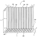
図2に、射出成形で形成した複合物品の一例を示す。複合物品216は、各々一つの連結部材220から延在した多数の未焼成セラミック素子218を含んでいる。図2に示す通り、連結部材220は長方形の形をしており、複合物品216の辺「x」と「z」に沿って延在している。連結部材220は厚さ「t」を有する。連結部材220は未焼成セラミック素子218と一体につながっている。
【0020】
発光性物質はX線透過方向(矢印210で示す)に厚さ「y」を有する。焼成後の厚さ「y」は通例約2〜4mmであるが、辺x及びzは各々通例約20〜40mmの長さを有する。焼成後のセラミック素子間の隙間は通例約100〜130ミクロンの幅である。これらの寸法が単なる例示にすぎないことはいうまでもない。
【0021】
図2に示す通り、シンチレーター列の各素子は反射層224で隔てられている。反射層224は列の個々の素子218内で発生した光を反射する。好ましくは、反射層は鏡面反射体ではなく、拡散反射体である。鏡面反射体ではいずれかの鏡面に当たった光が反射してシンチレーターバー内に戻る。結局、反射光の一部が後面に到達して検出される。この過程では幾つかのタイプの損失が生じ、光の出力は所望値よりも低くなる。例えば、光が垂直に近い入射角で鏡面反射面に当たると、後面に到達するまでに多数の反射が必要となる。銀のような優れた反射体でも反射するのは入射光の約95%にすぎず、その残りは吸収される。そこで、一回の反射で約5%の光が損失する。シンチレーターバーの表面で何回も反射すれば、ごく僅かな光しか残らない。さらに、面から面へと何度も反射する間、バー透過時にシンチレーター材料によって光が吸収される。対照的に、反射体ではなく散乱体として作用する拡散反射体では、こうした問題はかなり回避される。例えば、垂直入射角で拡散反射体に当たった光はほぼ余弦分布で放射される。そこで、バー内へと戻る入射エネルギーの割合は格段に高まり、その反射角度は後面に達するのに有効な浅い角度で、他の面との相互作用も減る。
【0022】
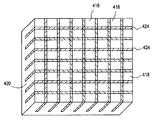
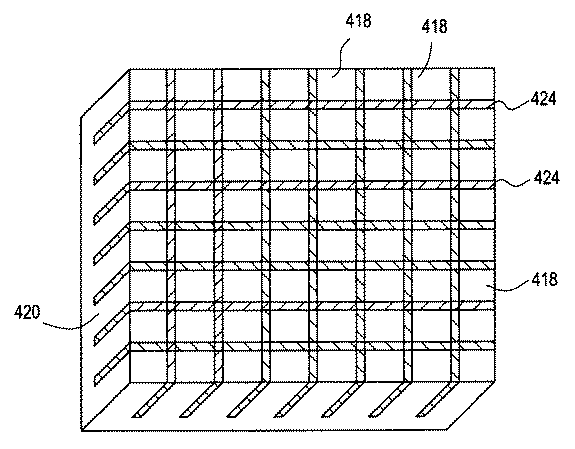
図4に、未焼成セラミック素子がグリッド又は画素構造の形態を取る本発明の別の実施形態を示す。反射体物質の充填された隙間424は直交する2方向に走っている。未焼成セラミック素子418は一つの連結部材420から延びる。
【0023】
未焼成セラミック素子の列の製造に使用し得るセラミック粉体の一例はGd2O3、Y2O3及び1種類以上の希土類酸化物賦活剤からなる。この実施形態では、シンチレーターバーは、Gd2O3約5〜50モル%、Eu2O3及びNd2O3からなる群から選択される希土類酸化物賦活剤約0.02〜12モル%、並びにPr2O3及びTb2O3からなる群から選択される1種類以上の残光低減剤約0.003〜0.5モル%から実質的になる組成を有する。このシンチレーター組成物の残部はY2O3である。
【0024】
この実施形態のセラミック粉体は、例えば純度99.99〜99.9999%のイットリア及びガドリニアのサブミクロン乃至ミクロン粉体を、酸化物、シュウ酸塩、炭酸塩もしくは硝酸塩の形態の所望の希土類賦活剤又はそれらの混合物と混合することによって調製できる。液体ビヒクルとして例えば水、ヘプタン又はアルコールを用いてメノウ乳鉢と乳棒又はボールミルで所定の成分を混合すればよい。乾式ミリングを混合及び粉体凝集物の解体のために用いてもよく、好ましくはボールミル内での粉体の詰まりや粘着を防ぐため1〜5重量%のステアリン酸又はオレイン酸のような粉砕助剤を用いる。化学成分を硝酸塩、炭酸塩又はシュウ酸塩の形態で添加したときは、通例、セラミックシンチレーターの製造前に対応酸化物を得るためのか焼段階が必要とされる。
【0025】
上述のシンチレーター材料のある具体的な製造方法では、ガドリニア、ユーロピア及びイットリアの酸化物化合物を硝酸に溶解して硝酸塩溶液とする。酸化プラセオジムを含む組成物では、Pr6O11も硝酸に溶解させる。次に、これら2種類の硝酸塩溶液を混合し、シュウ酸の過飽和溶液に添加して、共沈結晶性シュウ酸塩粉体を生じさせる。シュウ酸塩粉体を洗浄乾燥した後、約800℃の空気中での加熱によってか焼して所望の酸化物粉体を得る。
【0026】
酸化テルビウムを含む組成物では、Pr6O11に代えて又は加えてTb4O7を硝酸に溶解して硝酸塩溶液を生じさせ、これをガドリニア、ユーロピア及びイットリアの硝酸塩溶液と混合する。なお、Pr6O11及びTb4O7は、シンチレーター材料の製造法での焼成のような熱処理時にシンチレーター組成物中でそれぞれPr2O3とTb2O3へと転化する。ユーロピウムに代えて又は加えてネオジムを賦活剤として使用することもできる。この場合、Nd2O3を硝酸塩溶液に添加する。
【0027】
Eu2O3の望ましい濃度は約1〜6モル%である。Nd2O3は好ましくは約0.05〜1.5モル%の濃度で添加される。Gd2O3の濃度は一般に約5〜50モル%とし得る。この製造法のさらに詳しい説明は米国特許第5521387号に記載されており、その開示内容は文献の援用によって本明細書の内容の一部をなす。
【0028】
本発明の別の実施形態では、シンチレーター組成物は、母材ガーネットをX線又は光ルミネセンスのため適当なイオンで賦活化したものからなり、かかる賦活イオンには、例えばクロム、セリウム、ネオジムその他のカチオン又はこれらの混合物などがある。これらの材料の母材ガーネットは、例えばガドリニウムガリウムガーネット(Gd3Ga5O12)やイットリウムアルミニウムガーネット(Y3Al5O12)のような三元素系(2種カチオン)であってもよいし、或いは例えばガドリニウムスカンジウムガリウムガーネット(Gd3Sc2Ga3O12)やガドリニウムスカンジウムアルミニウムガーネット(Gd3Sc2Al3O12)のように4元素以上からなるものでもよい。
【0029】
かかる組成物のシンチレーター粉体原料は適量の所望カチオンの塩酸溶液を作ることによって調製できる。適量とは、所望の相対比のカチオンを含む最終透明物体が得られるような相対的濃度を意味する。例えば、カチオンがカチオン原料の塩酸溶液中での濃度と同じ相対濃度で最終透明物体中に存在するような場合には、その相対濃度は塩酸溶液中での所望濃度である。原料塩酸溶液を最終透明多結晶質物体へと転化させるプロセスで1種類以上のカチオンの量がその他のカチオンの量に対して相対的に減少する場合には、原料塩酸溶液における適量は所望の組成を有する最終透明ガーネット物体が得られるような量である。
【0030】
この原料塩化物溶液の一つの調製方法は、酸化物の形態の原料カチオンを熱濃塩酸に溶解することである。カチオン原料は所望により酸化物ではなく塩化物として準備してもよい。その他の原料化合物も使用できる。原料が熱濃塩酸に完全に溶解したら、得られた溶液を室温に冷却する。得られた溶液は透明で、いかなる原料の析出又は沈殿もあってはならない。原料の析出や沈殿が生じた場合には、溶液を再度加熱して、再度室温に冷却したときに析出や沈殿が全く起こらないように追加の塩酸を溶液に加えるべきである。換言すれば、原料が室温での溶解度以上に存在することがないように充分な塩酸を使用すべきである。
【0031】
これとは別個に、シュウ酸アンモニウム又はそれぞれの量のアンモニアとシュウ酸を溶解することによってシュウ酸アンモニウム(NH4)2C2O4溶液を形成する。カチオン含有塩化物溶液と完全に反応するように充分なシュウ酸アンモニウムを調製しなければならない。シュウ酸アンモニウム溶液は通例約7.5〜約9.5のpH、さらに典型的には8.0〜8.5のpHを有する。
【0032】
小バッチを作成する際には、シュウ酸アンモニウム溶液を攪拌しながらシュウ酸アンモニウム溶液に塩化物カチオン原料溶液を滴下してもよい。通例、これら2種類の溶液が接触すると白色析出物が生じる。少量調製する場合には、混合容器中に磁気攪拌棒を使うのが、これらの溶液を混合する好ましい方法である。塩化物原料溶液がすべてシュウ酸アンモニウム溶液に添加されれば、析出物の生成は完了する。
【0033】
この析出段階で、析出物は、最初シュウ酸塩溶液中に析出物がコロイド状に懸濁して存在する充分小さい粒子として形成される。析出段階の完了後、コロイド状懸濁物はゆっくりと沈降して、容器の底の白色の析出物とその上の透明な溶液が残る。この沈殿過程は析出物を含む液体をろ過及び/又は遠心することで促進し得る。
【0034】
所望により、液体から析出物を分離する前に析出物を水及び/又はアルコールで洗浄してもよい。そうするには、析出物を沈殿させ、液体を流し捨てるなどして大半の液体を除き、洗浄用の水又はアルコールを加え、析出物を再度沈殿させ、透明な液体を再度除去すればよい。最終的な透明ガーネットに高純度及び/又は厳密に制御された組成が望まれる場合には、洗浄水は高純度脱イオン水であるべきであり、アルコールは標準試薬級の純度のものであるべきである。この洗浄工程で過剰のシュウ酸アンモニウム及び塩化アンモニウムなどの反応生成物が析出物から除去される。析出物を次いでろ過、遠心その他の技術によって洗浄溶液から分離する。析出物は、例えば約110℃の温度で一日オーブン乾燥するか又は真空乾燥するなどして乾燥するのが好ましい。乾燥析出物を次いで空気中約750℃の温度に加熱して熱分解する。
【0035】
この粉体を通例ボールミルで、例えばジルコニア粉砕媒体とメチルアルコールやイソプロピルアルコールのような液体ビヒクルを用いて粉砕する。ボールミルによる粉砕時間は約4〜24時間が有効である。別法として、約60〜約100psiの設定圧力での流体エネルギーミリング又はジェットミリングを利用し得る。
【0036】
粉砕した粉体の粒度分布は通例約0.1〜2ミクロンの範囲である。この粉砕した粉体をプレスした圧粉体は理論密度まで焼成できる。賦活ガーネット系シンチレーターに適したセラミック粉体の製造法のさらに詳しい説明は米国特許第5484750号に開示されており、その開示内容は文献の援用によって本明細書の内容の一部をなす。
【0037】
所望のセラミック粉体を調製すれば、セラミック粉体から未焼成セラミック素子の列を形成できる。一実施形態では、セラミック粉体を適当なバインダーに分散させ、未焼成セラミック素子の列を射出成形によってニアネットシェイプに一体成形する。こうして一体成形した列は製造面で有利である。例えば、適当な反射体材料を素子間の隙間に充填することによって各セラミック素子に反射コーティングを容易に設けることができる。また、反射体材料とセラミック素子の同時焼成プロセスによって、焼成時のセラミック素子の寸法制御が向上し、ひいては従来の後段の加工段階がある程度或いは全く必要なくなる。
【0038】
射出成形工程では、セラミック粉体を適当なバインダーとブレンドする。このブレンド段階は、例えば高強度ミキサーで行うことができる。適当なバインダーの一例は、融点52〜58℃のパラフィンワックス33+1/3重量部、融点59〜63℃のパラフィンワックス33+1/3重量部、及び融点73〜80℃のパラフィンワックス33+1/3重量部からなる。これらパラフィンワックスはアルドリッチ・ケミカル(Aldrich Chemical)からそれぞれ製品番号317659、327212、及び411671として入手できる。パラフィンワックス100重量部に対して白蜜ろう4重量部、オレイン酸8重量部及びステアリン酸アルミニウム3重量部を添加する。
【0039】
別法として、バインダーは、例えば、蜜ろうのような低融点ワックスと、高融点のポリプロピレンやポリエチレン−エチルビニルアセテートコポリマーのようなポリマーと、ステアリン酸のような潤滑剤との組合せからなっていてもよい。セラミック粉体の射出成形に好適な他のバインダーは、例えば米国カリフォルニア州トランス(Torrance)のアライド・シグナル社(Allied Signal Inc.)及び米国ニューヨーク州バッファローのベンチマーク・セラミクス(Benchmark Ceramics)から市販されている。
【0040】
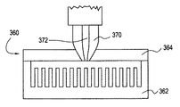
射出成形によって未焼成セラミック素子の列を製造する装置の一例を図3に示す。図3には、シンチレーター材料を収容したインジェクタ370と共に金型360が示してある。この射出成形プロセスでは、成形用組成物、例えば有機バインダーに分散したセラミック粉体を軟化点まで加熱し、インジェクタ370を用いて金型360内に射出して所望の形状とする。金型360は本体部362とカバー部364を含み得る。
【0041】
射出成形プロセスでは、インジェクタ370により通路372を介して金型をシンチレーター材料で充填する。シンチレーター材料は射出後金型内で冷えて硬化する。シンチレーター材料の硬化後にインジェクタと金型のカバー部364を外す。次に、成形品(この場合は未焼成セラミック素子の列)を金型から取り出す。射出成形後の未焼成セラミック素子の密度は通例理論密度の45〜65%である。
【0042】
本発明の例示的実施形態でニアネットシェイプの未焼成セラミック素子列を形成するその他の方法には、スリップキャスティングとゲルキャスティングがある。未焼成セラミック素子の列は、未焼成セラミック材料のブロックにダイヤモンドソーなどで溝を機械加工することによっても形成できる。未焼成セラミック材料のブロックはアイソスタティック成形、押出又は射出成形のような慣用法によって形成できる。
【0043】
次に、未焼成セラミック素子間の隙間を図2又は4に示す通り反射体材料で充填する。一実施形態では、反射体材料を適当な液体中に分散した反射体粉体からなる液体スラリーの形態で供給する。未焼成セラミック素子の列をスラリーに浸漬する。そうするには、例えば未焼成セラミック素子の列を適当な大きさの容器の内部に入れればよい。容器は通例、未焼成セラミック素子の列がスラリー中に完全に沈むようにその列の高さよりも高い側壁を有している。隙間及び列の上にスラリーを注入する。所望により、浸透を促進するために反射体スラリーを隙間に真空含浸してもよい。
【0044】
反射体粉体は、例えば、酸化イットリウム、酸化ジルコニウム、酸化ハフニウム、酸化タンタル、ランタニドの酸化物、アクチニドの酸化物のような耐熱酸化物、チタン酸バリウムのようなチタン酸塩、高融点アルミン酸塩、重金属酸化物のケイ酸塩、及びこれらの混合物を含み得る。適当な反射体粉体の一例は酸化イットリウム又は酸化イットリウムと気孔形成剤としての炭素との混合物である。反射体粉体は通例、高屈折率(例えば約1.80を超える屈折率)と、反射すべき光の波長の1/3〜2/3の平均粒径を有する。通例、シンチレーター用途には、シンチレーターバーで発生する光の波長は400〜700ナノメートルの範囲である。通例、反射体粉体は、反射体材料がシンチレーター材料と融合したり過剰に反応したりしないように高い融点(例えばシンチレーター材料の融点以上の融点)を有する。
【0045】
反射体粉体は、水又はアルコール類やオレフィン類のような有機溶媒などの適当な液体に分散し得る。ポリアルコール、アクリレート、アクリロイド及びアクリルアミドのような追加の有機バインダーを配合して乾燥スラリーに強度を与えてもよい。粉体の分散は、当技術分野で周知のように、高分子電解質などの適当な分散剤や湿潤剤を用いて促進し得る。
【0046】
未焼成セラミック素子の列にスラリーを充填した後、スラリーを乾燥又は空気硬化させて、固化した反射性物質と未焼成セラミック素子の列からなる複合物品を形成する。反射体スラリーは、例えば約80〜90℃に約7〜9時間加熱して反射体組成物中のバインダーを重合させることによっても硬化できる。所要に応じて、スラリーを酸化して炭素を燃焼させることもできる。
【0047】
本発明の別の実施形態では、反射性物質は別の方法で未焼成セラミック素子の列に充填できる。例えば、粉体をドライエアロゾルとして噴霧するなど加圧下で素子間の隙間に乾燥粉体を押し込むことによって、未焼成セラミック素子の列の表面上に反射層を形成することができる。未焼成セラミック素子間に挿入される乾燥粉体は未焼成セラミック素子と同一材料であってもよいが、粒度及び充填密度のいずれか又は両方が異なる。一例として、未焼成セラミック素子は密度が理論密度の約55〜65%で平均粒径が約0.5〜0.7ミクロンである賦活化イットリア−ガドリニア材(例えば、イットリアとガドリニアと上記のユーロピウムなどの1種類以上の希土類酸化物賦活剤からなる材料)からなり、反射体粉体は同じ賦活化イットリア−ガドリニア材からなるが、その密度は理論密度の約25〜35%であり、平均粒径は約0.2〜0.3ミクロンである。
【0048】
反射体粉体の充填密度の方が低いため、得られる反射体材料は焼成時に未焼成セラミック素子よりも低密度となり、収縮度は小さくなる。反射体材料の収縮度が小さいことで、焼成時にセラミック素子の列がその形状と寸法の完全性を維持する程度は反射体材料がない場合よりも高くなるという利点が得られる。得られる最終反射層の気孔は、その反射層に入ってくる光を散乱してシンチレーター素子へと戻す働きをし、素子間の光学的なクロストークを阻止する。
【0049】
未焼成セラミック素子間に反射層を設けるさらに別の方法では、モリブデンやタングステンのような耐熱金属箔を所望の反射体粉体で被覆し、被覆された箔をセラミック素子間の隙間に挿入し、得られた複合物品を焼成する。金属箔を被覆するには、例えば、アクリル系エマルションのようなバインダーに反射体粉体を分散させてペイントを作り、金属箔上に粉体を塗布することができる。金属中間層は追加の光障壁となり、シンチレーター素子間のクロストークをさらに低減する。
【0050】
未焼成セラミック素子の列又は反射体組成物が1種類以上のバインダーを含んでいる場合、通例、未焼成セラミック素子の列及び/又は反射体組成物からバインダーを除くため複合物品に対して予熱段階を実施する。予熱段階は、通例、加熱速度が毎時約3〜100℃で、温度範囲が120〜600℃で、加熱時間が6〜168時間、特に6〜48時間という加熱サイクルを含んでおり、かかる加熱サイクルは、有意の変形を起こさずに未焼成セラミック素子の列及び/又は反射体組成物から有機バインダーを除去するのに有効である。別法として、未焼成セラミック素子の列をその列の素子間に反射層を設ける前に予熱してバインダーを燃焼させてもよい。予熱段階後の未焼成セラミック素子の密度は通例理論密度の約55〜70%である。所望により、複合物品を予熱する段階、反射体組成物を硬化させる段階、及び複合物品を焼成する段階は、中間冷却を行わずに一回の加熱工程で実施することもできる。
【0051】
次に、複合物品を制御された雰囲気中高温で所望の時間焼成してセラミックの密度をほぼその理論密度まで高め、透明な物質を形成する。この焼成段階を実施するには、例えば、複合物品を真空中又は還元性もしくは酸化性の雰囲気中、毎時約100〜700℃の速度で、約1800〜2100℃の焼成温度まで加熱すればよい。焼成温度を約1〜30時間保った後、約2〜10時間かけて複合物品を室温まで冷却する。別法として、焼成工程は最終焼成温度よりも低い温度に保持する段階を含んでいてもよい。例えば、複合物品を毎時約300〜400℃の速度で約1600〜1700℃の保持温度まで加熱することができ、約1〜20時間保持した後、温度を毎時約25〜75℃の速度で約1800〜2100℃の温度に上げ、約1〜10時間の間最終焼成することができる。焼成とは、加熱によってセラミック材料の密度をその理論密度まで高める工程をいう。焼成シンチレーター材料は通例理論密度の99.9%を超える密度を有する。
【0052】
焼成後充填反射体領域は、粉体の特定の組成、焼成前の低い密度(通例、理論密度の25〜55%)、及び焼成後得られる低い密度(通例、理論密度の50〜99.5%、特に70〜80%)のため、不透明のままである。不透明な反射層はシンチレーターバーから放出された光を反射し、シンチレーターバーの1つで発生した実質的に全部の光が隣接するシンチレーターバーに伝播するのを阻止する。
【0053】
未焼成セラミック素子を緻密化して透明状態にすると共に反射層を部分的に焼成して不透明な反射体にする焼成工程の後、セラミック素子の列の連結部材220、420を慣用法で除去すればよい。その後、列の残りを所要の厚さ、通例は約3mmに仕上げ加工し、さらに加工してシンチレーターモジュールを形成することができる。
【0054】
通例、厚さ100ミクロン(4ミル)の最終反射性物質は98%を超える反射率が、3%未満の透過率、3%未満の可視波長吸光度、及び10%未満の放射線損傷を有する。放射線損傷は、1MRadのX線照射後の可視波長の反射能の変化と定義される。
【0055】
未焼成セラミック素子の列と介在反射体からなる複合物品を形成するさらに別の方法では、未焼成セラミック素子の間に反射体材料の層を挟み込んだサンドイッチ構造体を製造する。このためには、1)未焼成セラミック素子を所望の厚さの反射体層で被覆し、その組合せを積み重ねて所望の列を形成し、得られた複合構造体を焼成するか、2)未焼成セラミック素子上に所望の厚さの反射体粉体の層を形成し、そのような未焼成セラミック素子を多数作って列を形成し、得られた複合構造体を焼成するか、3)予めテープの形状に製造した反射体材料の層を未焼成セラミック素子間にサンドイッチ状に挟んでスタックを形成し、得られた複合構造体を焼成するか、或いは4)複数の未焼成セラミック素子をジグ中に並べ、複数のセラミック素子をスラリー中に浸漬し、スラリーを乾燥させ、得られた複合物品を焼成すればよい。
【0056】
【実施例】
イットリア−ガドリニア材からなる図2に示す未焼成セラミック素子の列を、36mlの脱イオン水、0.85gの分散剤Darvan 821A、2.0mlのNH4OH、及び50gの純度99.99%の蛍光体級のY2O3(モリー社(Moly Corporation))という組成を有する反射体スラリーと共に焼成した。スラリーペイントを5分間振盪した。次に、未焼成セラミック素子の列をビーカーに入れた。約半分のスラリーをビーカー中に注ぎ、列を覆った。ビーカーを真空チャンバに入れ、30分間真空に保った。次にビーカーを真空チャンバから取り出し、約1時間列を乾燥させた。次に未焼成セラミック素子の列をBrew炉に入れ、ほぼ理論密度まで焼成した。
【0057】
得られた物品はシンチレーターバーとその中に介在反射体層を有する複合構造体であった。この複合構造体の寸法を測定して、この具体例の方法によって達成された寸法安定性を確かめた。特に、各シンチレーターバーの幅(図2の「r」)と各反射層の幅(図2の「s」)をバーの長さに沿って3つの点(図2の「u」、「v」、「w」)で測定した。16のバーと反射体の平均と標準偏差(σ)のデータをミクロンで表に示す。
【0058】
【表1】
本発明のこの実施形態に従って形成された複合構造体を、反射体材料を介在させないで形成し焼成した類似の構造体(「比較構造体」)と比較した。比較構造体は研磨の際にシンチレーターバーの端が割れて破片になる傾向があるのでその寸法の測定は困難であった。しかし、目視で比較したところ、表1に記載した本発明の実施例で達成された寸法安定性は比較構造体の寸法安定性より明らかに優れていた。
【0060】
以上開示した実施形態を考慮すれば本発明の他の実施形態は当業者に明らかであろう。本明細書及び実施例は単なる例示であり、本発明の範囲と思想は特許請求の範囲に定義した通りである。
【図面の簡単な説明】
【図1】 本発明の一実施形態によるコンピュータ断層撮影スキャニングシステムの図である。
【図2】 本発明の一実施形態による、複数の未焼成セラミック素子と、これら素子間に介在反射物質とを含む複合物品の図である。
【図3】 未焼成セラミック素子の列を射出成形する装置の一例の図である。
【図4】 本発明の別の実施形態による、複数の未焼成セラミック素子と、これら素子間に介在反射物質とを含む複合物品の図である。
【符号の説明】
100 CTスキャニングシステム
114 X線源
116 シンチレーター検出器列
216 複合物品
218、418 未焼成セラミック素子
220、420 連結部材
224、424 隙間(反射層)[0001]
BACKGROUND OF THE INVENTION
The present invention relates to a ceramic in a broad sense, and more specifically, a composite comprising a luminescent ceramic material and an intervening reflective material obtained by simultaneously firing a first ceramic material and a second material. It relates to goods.
[0002]
[Prior art]
The luminescent material absorbs energy in one part of the electromagnetic spectrum and emits energy in a different part of the electromagnetic spectrum. Most luminescent materials, also called “phosphors” or “scintillators,” emit radiation in the visible region of the electromagnetic spectrum in response to absorption of radiation outside the visible region of the electromagnetic spectrum. The portion of the electromagnetic spectrum to which most phosphors respond is on the higher energy side of the visible region of the spectrum. For example, there are phosphors that respond to ultraviolet light (such as with fluorescent lamps), phosphors that respond to electrons (such as with cathode ray tubes), and phosphors that respond to X-rays (such as with X-ray imaging).
[0003]
An example of an application using a luminescent material is a computed tomography (CT) scanner. In the CT scanner, the X-ray source and the X-ray detector array are arranged on both sides of the subject, and the subject is rotated around the subject in a state where the positional relationship is fixed. Typically, CT scanners include a solid scintillator, which consists of a luminescent material in the form of a transparent solid. A typical detector array of a CT scanner includes a plurality of individual scintillator bars arranged with a photodetector diode coupled to each scintillator bar that converts the fluorescence into a corresponding electrical signal. The cell scintillator absorbs X-rays incident on the cell and emits light, and the light is collected by the photodetector of the cell. During data collection, each cell in the detector row provides an output signal that indicates the current light intensity of that cell in that row. Typically, the luminescent material in a CT scanner has a linear characteristic and its light output is a linear function of absorbed radiation dose, and its light output can be directly related to the excitation radiation intensity. The output signal is processed to produce an image of the subject as is well known in the CT scanner art.
[0004]
It is generally advantageous to provide a reflective coating on the surface of the scintillator bar other than the surface on which the photodetector diode is located. The coating reflects the light produced by the individual scintillator bars in the row. The reflective properties of the coating improve image accuracy by preventing light from traveling from one scintillator bar to another (commonly referred to as “crosstalk”).
[0005]
Various methods of forming a detector array consisting of a number of scintillator bars separated by a reflective layer are known in the art. Typically, the production of scintillator material is performed by preparing a suitable ceramic powder, grinding the powder, and pressing the powder to form a wafer. The wafer is then fired to a density typically exceeding 99% of theoretical density.
[0006]
One problem known to occur with conventional forming methods is that the wafer is warped during the firing stage. Such warping is caused by a difference in shrinkage due to non-uniform density distribution in the scintillator material. Depending on the application, the dimensional tolerance of the scintillator bar is very small, for example, less than 0.0013 cm (0.0005 inch), so the final size of the bar is achieved without further processing due to shrinkage differences when firing the scintillator bar Can be extremely difficult to do. Thus, the scintillator wafer is typically ground, lapped and polished to the desired dimensions after firing, but this is expensive and time consuming. The process of providing a reflective coating on the surface of the scintillator bar also requires a number of processing steps and can be expensive.
[0007]
Other methods of forming detector rows are known. For example, German Patent Application Publication No. 1970690A1 discloses a ceramic element having a layer structure including alternately a high-density layer and a highly porous layer. The porous layer includes micro structures that form bridges between adjacent high density layers. However, in this method, a detector array in which scintillator elements are optically coupled by a bridge can be obtained. However, this causes crosstalk and reduces the image accuracy of the device.
[0008]
German Patent Application Publication No. 19709691A1 discloses a method of manufacturing a structured ceramic element obtained by stacking and firing unfired ceramic elements having a spacer structure. After the green ceramic element is fired, a functional auxiliary material can be added to the cavities between the spacer structures. However, in this case as well, the spacer element is optically coupled with the ceramic element, which reduces the image accuracy of the device.
[0009]
[Problems to be solved by the invention]
Therefore, it is desired to develop a method for easily and effectively forming a detector array in which a reflective layer is interposed between scintillator bars, while avoiding the problems found in known methods.
[0010]
[Means for Solving the Problems]
In one embodiment of the present invention, a method of manufacturing a composite article includes the steps of forming a plurality of unfired ceramic elements arranged at intervals so as to form gaps, and filling the gaps with a second substance. And firing the unfired ceramic element with the second material to form a composite article. The second material functions as a reflective layer that prevents substantially all of the light in the fired ceramic element from reaching the adjacent fired ceramic element after firing. The plurality of unfired ceramic elements can be formed by injection molding, and each may extend from a common connecting member.
[0011]
The step of filling the gap may be performed by forming a slurry containing the second substance as a powder and immersing the unfired ceramic element in the slurry. This step of filling the gap can also be carried out by spraying a second substance in powder form into the gap. The second material filling the gap may be the same material used for forming the unfired ceramic element, but for example the filling density and / or the particle size are different.
[0012]
The process of firing the unfired ceramic element with the reflector composition improves dimensional control during firing and reduces processing costs.
[0013]
DETAILED DESCRIPTION OF THE INVENTION
Other features and advantages of the present invention will become apparent from the following detailed description and the accompanying drawings.
[0014]
FIG. 1 shows an example of a computed tomography (CT) scanning system. The
[0015]
Each
[0016]
The scintillator bars in the
[0017]
In one embodiment of the present invention, the
[0018]
In one embodiment of the present invention, the green ceramic element is prepared by preparing a suitable ceramic powder, dispersing the ceramic powder in a binder, and injecting the resulting composition into a row of green ceramic elements. It is formed by molding.
[0019]
FIG. 2 shows an example of a composite article formed by injection molding. The
[0020]
The luminescent material has a thickness “y” in the X-ray transmission direction (indicated by arrow 210). The fired thickness “y” is typically about 2-4 mm, while sides x and z each typically have a length of about 20-40 mm. The gap between the fired ceramic elements is typically about 100 to 130 microns wide. It goes without saying that these dimensions are merely illustrative.
[0021]
As shown in FIG. 2, each element of the scintillator array is separated by a
[0022]
FIG. 4 shows another embodiment of the present invention in which the green ceramic elements take the form of a grid or pixel structure. The
[0023]
An example of a ceramic powder that can be used to manufacture a row of unfired ceramic elements is Gd 2 O Three , Y 2 O Three And one or more rare earth oxide activators. In this embodiment, the scintillator bar is Gd 2 O Three About 5-50 mol%, Eu 2 O Three And Nd 2 O Three About 0.02 to 12 mol% of a rare earth oxide activator selected from the group consisting of 2 O Three And Tb 2 O Three Having a composition substantially consisting of about 0.003 to 0.5 mol% of one or more afterglow reducing agents selected from the group consisting of: The balance of the scintillator composition is Y 2 O Three It is.
[0024]
The ceramic powders of this embodiment are, for example, yttria and gadolinia submicron to micron powders with a purity of 99.99 to 99.9999%, which are activated with the desired rare earth activation in the form of oxide, oxalate, carbonate or nitrate. It can be prepared by mixing with agents or mixtures thereof. What is necessary is just to mix a predetermined component with an agate mortar, a pestle, or a ball mill using water, heptane, or alcohol as a liquid vehicle, for example. Dry milling may be used for mixing and disaggregation of powder agglomerates, preferably grinding aids such as 1-5 wt% stearic acid or oleic acid to prevent clogging and sticking of the powder in the ball mill. Use the agent. When chemical components are added in the form of nitrates, carbonates or oxalates, a calcination step is usually required to obtain the corresponding oxide prior to the production of the ceramic scintillator.
[0025]
In a specific manufacturing method of the above scintillator material, an oxide compound of gadolinia, europia and yttria is dissolved in nitric acid to form a nitrate solution. For compositions comprising praseodymium oxide, Pr 6 O 11 Also dissolve in nitric acid. Next, these two types of nitrate solutions are mixed and added to a supersaturated solution of oxalic acid to produce a coprecipitated crystalline oxalate powder. The oxalate powder is washed and dried and then calcined by heating in air at about 800 ° C. to obtain a desired oxide powder.
[0026]
For compositions containing terbium oxide, Pr 6 O 11 Instead of or in addition to Tb Four O 7 Is dissolved in nitric acid to form a nitrate solution, which is mixed with gadolinia, europia and yttria nitrate solutions. Pr 6 O 11 And Tb Four O 7 Each in the scintillator composition during a heat treatment such as firing in a method of manufacturing a scintillator material. 2 O Three And Tb 2 O Three Convert to. Neodymium can also be used as an activator instead of or in addition to europium. In this case, Nd 2 O Three Is added to the nitrate solution.
[0027]
Eu 2 O Three The desired concentration of is about 1-6 mol%. Nd 2 O Three Is preferably added at a concentration of about 0.05 to 1.5 mole percent. Gd 2 O Three The concentration of can generally be about 5-50 mol%. A more detailed description of this process is described in US Pat. No. 5,521,387, the disclosure of which is incorporated herein by reference.
[0028]
In another embodiment of the present invention, the scintillator composition comprises a matrix garnet activated with suitable ions for X-rays or photoluminescence, including such activated ions as chromium, cerium, neodymium, etc. Or a mixture thereof. The base material garnet of these materials is, for example, gadolinium gallium garnet (Gd Three Ga Five O 12 ) And yttrium aluminum garnet (Y Three Al Five O 12 ), Or a gadolinium scandium gallium garnet (Gd). Three Sc 2 Ga Three O 12 ) And gadolinium scandium aluminum garnet (Gd Three Sc 2 Al Three O 12 4) or more may be used.
[0029]
The scintillator powder material of such a composition can be prepared by making a suitable amount of a hydrochloric acid solution of the desired cation. By proper amount is meant a relative concentration such that a final transparent object containing the desired relative ratio of cations is obtained. For example, if the cation is present in the final transparent body at the same relative concentration as the concentration of the cation raw material in the hydrochloric acid solution, the relative concentration is the desired concentration in the hydrochloric acid solution. If the process of converting the raw hydrochloric acid solution into the final transparent polycrystalline body reduces the amount of one or more cations relative to the amount of other cations, the appropriate amount in the raw hydrochloric acid solution is the desired composition. In such an amount that a final transparent garnet object having is obtained.
[0030]
One method of preparing this raw material chloride solution is to dissolve the raw material cation in the form of an oxide in hot concentrated hydrochloric acid. If desired, the cation raw material may be prepared as a chloride instead of an oxide. Other raw material compounds can also be used. When the raw material is completely dissolved in hot concentrated hydrochloric acid, the resulting solution is cooled to room temperature. The resulting solution should be clear and free from any material precipitation or precipitation. If precipitation or precipitation of the raw material occurs, additional hydrochloric acid should be added to the solution so that no precipitation or precipitation occurs when the solution is heated again and cooled to room temperature again. In other words, enough hydrochloric acid should be used so that the raw material does not exist above the solubility at room temperature.
[0031]
Separately, ammonium oxalate (NH) can be obtained by dissolving ammonium oxalate or the respective amounts of ammonia and oxalic acid. Four ) 2 C 2 O Four Form a solution. Sufficient ammonium oxalate must be prepared to react completely with the cation-containing chloride solution. The ammonium oxalate solution typically has a pH of about 7.5 to about 9.5, more typically a pH of 8.0 to 8.5.
[0032]
When preparing a small batch, the chloride cation raw material solution may be dropped into the ammonium oxalate solution while stirring the ammonium oxalate solution. Typically, when these two solutions come into contact, a white precipitate is formed. In the case of preparing a small amount, a magnetic stirring bar is used in a mixing container, which is a preferable method for mixing these solutions. When all the chloride raw material solution is added to the ammonium oxalate solution, the formation of the precipitate is complete.
[0033]
In this precipitation stage, the precipitate is first formed as sufficiently small particles in which the precipitate is present in a colloidal suspension in the oxalate solution. After completion of the precipitation stage, the colloidal suspension slowly settles, leaving a white precipitate at the bottom of the container and a clear solution above it. This precipitation process can be facilitated by filtering and / or centrifuging the liquid containing the precipitate.
[0034]
If desired, the precipitate may be washed with water and / or alcohol before separating the precipitate from the liquid. In order to do so, the precipitate is precipitated, the liquid is poured and discarded to remove most of the liquid, washing water or alcohol is added, the precipitate is precipitated again, and the transparent liquid is removed again. If high purity and / or tightly controlled composition is desired in the final clear garnet, the wash water should be high purity deionized water and the alcohol should be of standard reagent grade purity It is. In this washing step, reaction products such as excess ammonium oxalate and ammonium chloride are removed from the precipitate. The precipitate is then separated from the wash solution by filtration, centrifugation or other techniques. The precipitate is preferably dried by, for example, oven drying at a temperature of about 110 ° C. for one day or vacuum drying. The dried precipitate is then thermally decomposed by heating to a temperature of about 750 ° C. in air.
[0035]
This powder is typically pulverized in a ball mill using, for example, a zirconia grinding medium and a liquid vehicle such as methyl alcohol or isopropyl alcohol. The grinding time by the ball mill is about 4 to 24 hours. Alternatively, fluid energy milling or jet milling at a set pressure of about 60 to about 100 psi may be utilized.
[0036]
The particle size distribution of the milled powder is typically in the range of about 0.1 to 2 microns. A green compact obtained by pressing the pulverized powder can be fired to a theoretical density. A more detailed description of a method for producing a ceramic powder suitable for an activated garnet scintillator is disclosed in US Pat. No. 5,484,750, the disclosure of which is incorporated herein by reference.
[0037]
Once the desired ceramic powder is prepared, a row of unfired ceramic elements can be formed from the ceramic powder. In one embodiment, the ceramic powder is dispersed in a suitable binder and the rows of unfired ceramic elements are integrally formed into a near net shape by injection molding. The integrally formed row is advantageous in terms of manufacturing. For example, each ceramic element can be easily provided with a reflective coating by filling the gap between the elements with a suitable reflector material. In addition, the simultaneous firing process of the reflector material and the ceramic element improves the dimensional control of the ceramic element during firing, and as a result, some or no conventional subsequent processing steps are required.
[0038]
In the injection molding process, the ceramic powder is blended with a suitable binder. This blending step can be performed, for example, with a high-strength mixer. Examples of suitable binders include 33 + 1/3 parts by weight paraffin wax having a melting point of 52-58 ° C, 33 + 1/3 parts by weight paraffin wax having a melting point of 59-63 ° C, and 33 + 1/3 parts by weight paraffin wax having a melting point of 73-80 ° C. Become. These paraffin waxes are available from Aldrich Chemical as product numbers 317659, 327212, and 411671, respectively. 4 parts by weight of white beeswax, 8 parts by weight of oleic acid and 3 parts by weight of aluminum stearate are added to 100 parts by weight of paraffin wax.
[0039]
Alternatively, the binder consists of a combination of a low melting wax such as beeswax, a polymer such as a high melting polypropylene or polyethylene-ethyl vinyl acetate copolymer, and a lubricant such as stearic acid. Also good. Other binders suitable for ceramic powder injection molding are commercially available, for example, from Allied Signal Inc. in Torrance, California, USA and Benchmark Ceramics, Buffalo, NY, USA. Yes.
[0040]
An example of an apparatus for producing a row of unfired ceramic elements by injection molding is shown in FIG. FIG. 3 shows a
[0041]
In the injection molding process, the mold is filled with scintillator material via a
[0042]
Other methods of forming a near net shape green ceramic element array in an exemplary embodiment of the present invention include slip casting and gel casting. An array of unfired ceramic elements can also be formed by machining grooves in a block of unfired ceramic material with a diamond saw or the like. The block of green ceramic material can be formed by conventional methods such as isostatic molding, extrusion or injection molding.
[0043]
Next, the gaps between the unfired ceramic elements are filled with a reflector material as shown in FIG. In one embodiment, the reflector material is provided in the form of a liquid slurry consisting of reflector powder dispersed in a suitable liquid. A row of green ceramic elements is immersed in the slurry. To do so, for example, a row of unfired ceramic elements may be placed inside an appropriately sized container. The container typically has sidewalls that are higher than the height of the row so that the row of green ceramic elements completely sinks into the slurry. Inject slurry over gaps and rows. If desired, the reflector slurry may be vacuum impregnated into the gap to facilitate penetration.
[0044]
Reflector powders include, for example, yttrium oxide, zirconium oxide, hafnium oxide, tantalum oxide, lanthanide oxide, refractory oxide such as actinide oxide, titanate such as barium titanate, and high melting point aluminate Salts, heavy metal oxide silicates, and mixtures thereof may be included. An example of a suitable reflector powder is yttrium oxide or a mixture of yttrium oxide and carbon as a pore former. The reflector powder typically has a high refractive index (eg, a refractive index greater than about 1.80) and an average particle size of 1/3 to 2/3 of the wavelength of light to be reflected. Typically, for scintillator applications, the wavelength of light generated by the scintillator bar ranges from 400 to 700 nanometers. Typically, the reflector powder has a high melting point (eg, a melting point above the melting point of the scintillator material) so that the reflector material does not fuse or react excessively with the scintillator material.
[0045]
The reflector powder can be dispersed in a suitable liquid such as water or an organic solvent such as alcohols or olefins. Additional organic binders such as polyalcohols, acrylates, acryloids and acrylamides may be included to give strength to the dried slurry. Dispersion of the powder can be facilitated using a suitable dispersant or wetting agent such as a polymer electrolyte, as is well known in the art.
[0046]
After the rows of unfired ceramic elements are filled with the slurry, the slurry is dried or air cured to form a composite article comprising the solidified reflective material and the rows of unfired ceramic elements. The reflector slurry can also be cured, for example, by heating to about 80-90 ° C. for about 7-9 hours to polymerize the binder in the reflector composition. If necessary, the slurry can be oxidized to burn carbon.
[0047]
In another embodiment of the present invention, the reflective material can be filled into the rows of green ceramic elements in other ways. For example, the reflective layer can be formed on the surface of the row of unfired ceramic elements by pressing the dry powder into the gaps between the elements under pressure, such as by spraying the powder as a dry aerosol. The dry powder inserted between the unfired ceramic elements may be the same material as the unfired ceramic element, but either or both of the particle size and packing density are different. As an example, the green ceramic element has an activated yttria-gadolinia material having a density of about 55-65% of the theoretical density and an average particle size of about 0.5-0.7 microns (eg, yttria, gadolinia, and europium as described above). The reflector powder is made of the same activated yttria-gadolinia material, but the density is about 25 to 35% of the theoretical density, and the average particle The diameter is about 0.2 to 0.3 microns.
[0048]
Since the packing density of the reflector powder is lower, the resulting reflector material has a lower density than the unfired ceramic element during firing, and the degree of shrinkage is small. The small degree of shrinkage of the reflector material has the advantage that the degree to which the array of ceramic elements maintains their shape and dimensional integrity during firing is higher than without the reflector material. The resulting pores of the final reflective layer function to scatter light entering the reflective layer and return it to the scintillator elements, thereby preventing optical crosstalk between the elements.
[0049]
In yet another method of providing a reflective layer between unfired ceramic elements, a heat resistant metal foil such as molybdenum or tungsten is coated with the desired reflector powder, and the coated foil is inserted into the gap between the ceramic elements, The obtained composite article is fired. In order to coat the metal foil, for example, a reflector powder can be dispersed in a binder such as an acrylic emulsion to make a paint, and the powder can be applied on the metal foil. The metal intermediate layer provides an additional light barrier and further reduces crosstalk between scintillator elements.
[0050]
If the green ceramic element array or reflector composition includes one or more binders, it is typically a preheating stage for the composite article to remove the binder from the green ceramic element array and / or reflector composition. To implement. The preheating stage typically includes a heating cycle with a heating rate of about 3 to 100 ° C. per hour, a temperature range of 120 to 600 ° C., and a heating time of 6 to 168 hours, especially 6 to 48 hours. Is effective in removing organic binder from the array of green ceramic elements and / or reflector composition without significant deformation. Alternatively, the rows of unfired ceramic elements may be preheated and the binder burned before providing a reflective layer between the elements in that row. The density of the green ceramic element after the preheating stage is typically about 55 to 70% of the theoretical density. If desired, the steps of preheating the composite article, curing the reflector composition, and firing the composite article can be performed in a single heating step without intermediate cooling.
[0051]
The composite article is then fired at a high temperature in a controlled atmosphere for a desired time to increase the density of the ceramic to approximately its theoretical density and form a transparent material. To perform this firing step, for example, the composite article may be heated to a firing temperature of about 1800-2100 ° C. at a rate of about 100-700 ° C. per hour in a vacuum or reducing or oxidizing atmosphere. After maintaining the firing temperature for about 1-30 hours, the composite article is cooled to room temperature over about 2-10 hours. Alternatively, the firing step may include the step of holding at a temperature lower than the final firing temperature. For example, the composite article can be heated at a rate of about 300-400 ° C. per hour to a holding temperature of about 1600-1700 ° C., and after holding for about 1-20 hours, the temperature is increased at a rate of about 25-75 ° C. per hour. The temperature can be raised to 1800-2100 ° C. and final firing can be performed for about 1-10 hours. Firing refers to the process of raising the density of the ceramic material to its theoretical density by heating. The fired scintillator material typically has a density that exceeds 99.9% of the theoretical density.
[0052]
The post-fired filled reflector region has a specific composition of the powder, a low density before firing (typically 25-55% of the theoretical density), and a low density obtained after firing (typically 50-99.5 of the theoretical density). %, Especially 70-80%). The opaque reflective layer reflects light emitted from the scintillator bar and blocks substantially all of the light generated by one of the scintillator bars from propagating to the adjacent scintillator bar.
[0053]
After the firing step of densifying the unfired ceramic element to make it transparent and partially firing the reflective layer to make an opaque reflector, the connecting
[0054]
Typically, a final reflective material that is 100 microns (4 mils) thick has a reflectivity greater than 98%, less than 3% transmission, less than 3% visible wavelength absorbance, and less than 10% radiation damage. Radiation damage is defined as the change in reflectivity of visible wavelengths after 1 MRad X-ray irradiation.
[0055]
In yet another method of forming a composite article comprising an array of green ceramic elements and intervening reflectors, a sandwich structure is produced in which a layer of reflector material is sandwiched between green ceramic elements. To this end, 1) the green ceramic element is coated with a reflector layer of the desired thickness and the combination is stacked to form the desired row and the resulting composite structure is fired, or 2) A layer of reflector powder having a desired thickness is formed on a fired ceramic element, and a number of such unfired ceramic elements are formed to form a row, and the resulting composite structure is fired. A stack of reflector materials made in the form of a tape is sandwiched between unfired ceramic elements to form a stack and the resulting composite structure is fired, or 4) a plurality of unfired ceramic elements are jigged A plurality of ceramic elements may be immersed in the slurry, the slurry may be dried, and the resulting composite article may be fired.
[0056]
【Example】
An array of the unfired ceramic elements shown in FIG. 2 made of yttria-gadolinia material is replaced with 36 ml deionized water, 0.85 g dispersant Darvan 821A, 2.0 ml NH. Four OH and 50 g of phosphor grade Y with a purity of 99.99% 2 O Three It was fired with a reflector slurry having the composition (Moly Corporation). The slurry paint was shaken for 5 minutes. Next, a row of unfired ceramic elements was placed in a beaker. About half of the slurry was poured into a beaker and covered the row. The beaker was placed in a vacuum chamber and kept under vacuum for 30 minutes. The beaker was then removed from the vacuum chamber and the train was allowed to dry for about 1 hour. The row of unfired ceramic elements was then placed in a Brew furnace and fired to near theoretical density.
[0057]
The resulting article was a composite structure having a scintillator bar and an intervening reflector layer therein. The dimensions of this composite structure were measured to confirm the dimensional stability achieved by this example method. Specifically, the width of each scintillator bar (“r” in FIG. 2) and the width of each reflective layer (“s” in FIG. 2) are divided into three points (“u”, “v” in FIG. 2) along the length of the bar. ”,“ W ”). The average and standard deviation (σ) data for 16 bars and reflectors are shown in microns in the table.
[0058]
[Table 1]
A composite structure formed in accordance with this embodiment of the invention was compared to a similar structure ("comparative structure") that was formed and fired without intervening reflector material. Since the end of the scintillator bar tends to crack and become broken pieces during polishing, it was difficult to measure the dimensions of the comparative structure. However, when compared visually, the dimensional stability achieved in the examples of the invention described in Table 1 was clearly superior to the dimensional stability of the comparative structure.
[0060]
Other embodiments of the invention will be apparent to those skilled in the art in view of the embodiments disclosed above. The specification and examples are merely illustrative and the scope and spirit of the invention are as defined in the claims.
[Brief description of the drawings]
FIG. 1 is a diagram of a computed tomography scanning system according to one embodiment of the present invention.
FIG. 2 is a diagram of a composite article comprising a plurality of green ceramic elements and intervening reflective materials between the elements, according to one embodiment of the present invention.
FIG. 3 is a diagram of an example of an apparatus for injection molding a row of unfired ceramic elements.
FIG. 4 is a diagram of a composite article comprising a plurality of green ceramic elements and intervening reflective materials between the elements according to another embodiment of the present invention.
[Explanation of symbols]
100 CT scanning system
114 X-ray source
116 Scintillator detector array
216 Composite articles
218, 418 Unfired ceramic element
220, 420 connecting member
224, 424 Gap (reflection layer)
Claims (26)
互いに隙間ができるように間隔をおいて並んだ複数の未焼成セラミック素子を形成する段階、
上記隙間を第二の物質で充填する段階、及び
第二の物質と共に未焼成セラミック素子を焼成してセラミックシンチレーター物品を形成する段階
を含んでなり、上記第二の物質が焼成後に焼成セラミック素子内の光が隣接する焼成セラミック素子に到達するのを防ぐ、方法。A method of manufacturing a ceramic scintillator article, the method comprising:
Forming a plurality of unfired ceramic elements that are spaced apart to form a gap between each other;
Filling the gap with a second material, and firing a green ceramic element together with the second material to form a ceramic scintillator article, wherein the second material is fired within the fired ceramic element after firing. To prevent the light from reaching the adjacent fired ceramic element.
第二の物質を粉体として含むスラリーを形成する段階、及び
上記スラリー中に未焼成セラミック素子を浸漬する段階
を含んでなる、請求項1又は請求項2記載の方法。Filling the gap comprises:
The method according to claim 1 or 2, comprising the steps of: forming a slurry containing the second substance as a powder; and immersing the green ceramic element in the slurry.
金属箔を前記第二の物質で被覆する段階、及び
上記金属箔を隙間に挿入する段階
を含んでなる、請求項1又は請求項2記載の方法。Filling the gap comprises:
3. A method according to claim 1 or claim 2 comprising the steps of coating a metal foil with the second substance and inserting the metal foil into the gap.
第一のセラミック物質からなる第一の充填密度を有する第一の粉体から複数の未焼成セラミック素子を形成する段階、
第二のセラミック物質からなる第二の充填密度を有する第二の粉体で前記未焼成セラミック素子間の隙間を充填する段階、及び
上記第二の粉体と共に未焼成セラミック素子を焼成してセラミックシンチレーター構造体を形成する段階
を含んでなり、第一のセラミック物質が第二のセラミック物質と同一であるが、第一の充填密度が第二の充填密度と異なる、方法。A method for producing a ceramic scintillator structure, the method comprising:
Forming a plurality of green ceramic elements from a first powder having a first packing density of a first ceramic material;
Filling a gap between the unfired ceramic elements with a second powder having a second filling density made of a second ceramic material, and firing the unfired ceramic element together with the second powder to produce a ceramic Forming a scintillator structure, wherein the first ceramic material is the same as the second ceramic material, but the first packing density is different from the second packing density.
一つの連結部材から延在していて該連結部材のみで連結している複数の未焼成セラミック素子を含む第一の部品であって、それら未焼成セラミック素子同士の間に隙間が画成される第一の部品を形成する段階、
上記隙間を第二の物質からなるセラミック粉体で充填する段階、及び
セラミック粉体と共に未焼成セラミック素子を焼成してセラミックシンチレーター物品を形成する段階
を含んでなる、方法。A method of manufacturing a ceramic scintillator article, the method comprising:
A first part including a plurality of unfired ceramic elements extending from one connecting member and connected only by the connecting member, wherein a gap is defined between the unfired ceramic elements. Forming a first part;
Filling the gap with a ceramic powder comprising a second material, and firing a green ceramic element with the ceramic powder to form a ceramic scintillator article.
第二の物質を粉体として含むスラリーを形成する段階、及び
上記スラリー中に未焼成セラミック素子を浸漬する段階
を含んでなる、請求項20記載の方法。Filling the gap comprises:
21. The method of claim 20, comprising forming a slurry containing the second material as a powder, and immersing the green ceramic element in the slurry.
金属箔を第二の物質で被覆する段階、及び
上記金属箔を隙間に挿入する段階
を含んでなる、請求項20記載の方法。Filling the gap comprises:
21. The method of claim 20, comprising: coating the metal foil with a second material; and inserting the metal foil into the gap.
Applications Claiming Priority (2)
| Application Number | Priority Date | Filing Date | Title |
|---|---|---|---|
| US09/388091 | 1999-09-01 | ||
| US09/388,091 US6361735B1 (en) | 1999-09-01 | 1999-09-01 | Composite ceramic article and method of making |
Publications (2)
| Publication Number | Publication Date |
|---|---|
| JP2001220232A JP2001220232A (en) | 2001-08-14 |
| JP4792155B2 true JP4792155B2 (en) | 2011-10-12 |
Family
ID=23532649
Family Applications (1)
| Application Number | Title | Priority Date | Filing Date |
|---|---|---|---|
| JP2000262014A Expired - Fee Related JP4792155B2 (en) | 1999-09-01 | 2000-08-31 | Composite ceramic article and manufacturing method thereof |
Country Status (3)
| Country | Link |
|---|---|
| US (1) | US6361735B1 (en) |
| JP (1) | JP4792155B2 (en) |
| DE (1) | DE10042608B4 (en) |
Families Citing this family (19)
| Publication number | Priority date | Publication date | Assignee | Title |
|---|---|---|---|---|
| US20030226978A1 (en) * | 1998-01-30 | 2003-12-11 | Segan Industries | Integrating ultraviolet exposure detection devices |
| EP1238956A1 (en) * | 2001-03-10 | 2002-09-11 | Vita Zahnfabrik H. Rauter GmbH & Co. KG | Composite material and method of making it |
| DE10211948A1 (en) * | 2002-03-18 | 2003-10-09 | Siemens Ag | X-ray computer tomography detector |
| US20060033030A1 (en) * | 2002-03-28 | 2006-02-16 | Kabushiki Kaisha Toshiba | X-ray detector |
| JP2004136647A (en) * | 2002-06-06 | 2004-05-13 | Ngk Insulators Ltd | Manufacturing method of composite sintered body, manufacturing method of composite molded body, and composite sintered body and composite molded body |
| US20050104000A1 (en) * | 2003-02-10 | 2005-05-19 | Joel Kindem | Scintillator assembly with pre-formed reflector |
| CN101505938A (en) * | 2006-08-16 | 2009-08-12 | 圣戈本陶瓷及塑料股份有限公司 | Injection molding of ceramic elements |
| PT2036694E (en) | 2007-09-17 | 2014-06-12 | Scg Building Materials Co Ltd | Apparatus and method for forming a pattern in ceramic tile or slab with prescribed thickness |
| CN102484200B (en) * | 2009-06-19 | 2015-11-25 | 索纳维森股份有限公司 | Manufacturing method of piezoelectric ceramic body |
| JP5749148B2 (en) * | 2011-12-21 | 2015-07-15 | ジーイー・メディカル・システムズ・グローバル・テクノロジー・カンパニー・エルエルシー | Radiation tomography apparatus, radiation detection apparatus, and spatial resolution switching method in radiation tomography |
| WO2013140444A1 (en) * | 2012-03-21 | 2013-09-26 | 株式会社島津製作所 | Scintillator, method for producing same, radiation detector, and method for producing same |
| KR20140055318A (en) * | 2012-10-31 | 2014-05-09 | 삼성전자주식회사 | A collimator module, a detector having the collimator module, a radiological imaging apparatus having the collimator module and method for controlling the radiological imaging apparatus |
| US11569494B2 (en) * | 2013-10-23 | 2023-01-31 | Cps Technology Holdings Llc | Aqueous cathode slurry |
| DE102014213039A1 (en) * | 2014-07-04 | 2016-01-07 | Siemens Aktiengesellschaft | Method for edge coating on semiconductor detectors |
| CN107004686B (en) * | 2014-11-13 | 2021-07-20 | 皇家飞利浦有限公司 | Pixelated scintillator with optimized efficiency |
| US10150914B2 (en) * | 2015-11-25 | 2018-12-11 | Siemens Medical Solutions Usa, Inc. | Ceramic phoswich with fused optical elements, method of manufacture thereof and articles comprising the same |
| US10197685B2 (en) * | 2015-12-01 | 2019-02-05 | Siemens Medical Solutions Usa, Inc. | Method for controlling gallium content in gadolinium-gallium garnet scintillators |
| US10961452B2 (en) | 2015-12-01 | 2021-03-30 | Siemens Medical Solutions Usa, Inc. | Method for controlling gallium content in gadolinium-gallium garnet scintillators |
| CN116573933B (en) * | 2023-05-30 | 2025-05-06 | 先导薄膜材料(淄博)有限公司 | Zirconia ceramic stacking sintering method |
Family Cites Families (36)
| Publication number | Priority date | Publication date | Assignee | Title |
|---|---|---|---|---|
| US4362946A (en) | 1977-11-21 | 1982-12-07 | General Electric Company | Distributed phosphor scintillator structures |
| JPS5930882A (en) * | 1982-06-18 | 1984-02-18 | ゼネラル・エレクトリツク・カンパニイ | Rare earth element-added yttria-gadolinia ceramic scintillator and manufacture |
| US4533489A (en) | 1983-12-07 | 1985-08-06 | Harshaw/Filtrol Partnership | Formable light reflective compositions |
| JPS61271486A (en) * | 1985-05-28 | 1986-12-01 | Hamamatsu Photonics Kk | Apparatus for detecting incident position of radiation |
| JPS61290007A (en) * | 1985-06-18 | 1986-12-20 | トヨタ自動車株式会社 | Manufacture of ceramic product |
| IL80333A (en) | 1985-12-30 | 1991-01-31 | Gen Electric | Radiation detector employing solid state scintillator material and preparation methods therefor |
| US4720426A (en) | 1986-06-30 | 1988-01-19 | General Electric Company | Reflective coating for solid-state scintillator bar |
| US4870279A (en) * | 1988-06-20 | 1989-09-26 | General Electric Company | High resolution X-ray detector |
| US5013696A (en) | 1989-09-25 | 1991-05-07 | General Electric Company | Preparation of high uniformity polycrystalline ceramics by presintering, hot isostatic pressing and sintering and the resulting ceramic |
| EP0464224B1 (en) * | 1990-01-25 | 2000-10-11 | Dai Nippon Insatsu Kabushiki Kaisha | Method of and material for forming thick filmy pattern |
| DE4101645A1 (en) * | 1990-01-29 | 1991-08-01 | Gen Electric | TWO-DIMENSIONAL MOSAIC SCINTILLATION DETECTOR |
| CA2042147A1 (en) * | 1990-06-29 | 1991-12-30 | Veneta G. Tsoukala | Hole-trap-compensated scintillator material |
| CA2042263A1 (en) | 1990-06-29 | 1991-12-30 | Charles D. Greskovich | Transparent polycrystalline garnets |
| US5100598A (en) | 1991-02-19 | 1992-03-31 | General Electric Company | Method of forming yttria-gadolinia ceramic scintillator from ammonium dispersed oxalate precipitates |
| US5116559A (en) | 1991-02-26 | 1992-05-26 | General Electric Company | Method of forming yttria-gadolinia ceramic scintillator using hydroxide coprecipitation step |
| US5116560A (en) | 1991-03-22 | 1992-05-26 | General Electric Company | Method of forming rare earth oxide ceramic scintillator with ammonium dispersion of oxalate precipitates |
| JPH0519060A (en) * | 1991-07-10 | 1993-01-26 | Shin Etsu Chem Co Ltd | Scintillator manufacturing method |
| US5208460A (en) * | 1991-09-23 | 1993-05-04 | General Electric Company | Photodetector scintillator radiation imager having high efficiency light collection |
| US5239736A (en) | 1991-11-12 | 1993-08-31 | Acuson Corporation | Method for making piezoelectric composites |
| US5453623A (en) | 1992-05-13 | 1995-09-26 | Board Of Regents, The University Of Texas System | Positron emission tomography camera with quadrant-sharing photomultipliers and cross-coupled scintillating crystals |
| DE4224931C2 (en) | 1992-07-28 | 1995-11-23 | Siemens Ag | Process for producing a scintillator ceramic and its use |
| US5338598A (en) * | 1992-12-14 | 1994-08-16 | Corning Incorporated | Sintered inorganic composites comprising co-sintered tape reinforcement |
| KR0179404B1 (en) * | 1993-02-02 | 1999-05-15 | 모리시타 요이찌 | Ceramic substrate and manufacturing method thereof |
| US5340510A (en) * | 1993-04-05 | 1994-08-23 | Materials Systems Incorporated | Method for making piezoelectric ceramic/polymer composite transducers |
| JP3340793B2 (en) | 1993-05-27 | 2002-11-05 | 株式会社日立メディコ | Radiation detector |
| US5497540A (en) | 1994-12-22 | 1996-03-12 | General Electric Company | Method for fabricating high density ultrasound array |
| US5818149A (en) * | 1996-03-25 | 1998-10-06 | Rutgers, The State University Of New Jersey | Ceramic composites and methods for producing same |
| DE19643148C2 (en) | 1996-10-18 | 2003-08-28 | Epcos Ag | Manufacturing process for ceramic bodies with microstructure and uses |
| DE19709691A1 (en) | 1997-03-10 | 1998-09-17 | Siemens Ag | Structured ceramic body production |
| DE19709690A1 (en) | 1997-03-10 | 1998-09-17 | Siemens Ag | Multilayer ceramic body with monolithic structure |
| JP2840941B2 (en) * | 1997-04-02 | 1998-12-24 | 株式会社日立メディコ | Multi-element radiation detector and manufacturing method thereof |
| JPH10319126A (en) * | 1997-05-16 | 1998-12-04 | S I I R D Center:Kk | Radiation detector and its manufacturing method |
| JP3565472B2 (en) * | 1997-09-01 | 2004-09-15 | 信越化学工業株式会社 | Method for producing monodispersed spherical particles of yttria / gadolinia / europia coprecipitated and monodispersed spherical particles of yttria / gadolinia / europia obtained therefrom |
| JP3104696B2 (en) * | 1998-12-21 | 2000-10-30 | 日立金属株式会社 | Radiation detector and radiation CT apparatus using the same |
| US6252231B1 (en) * | 1999-01-25 | 2001-06-26 | Analogic Corporation | X-ray absorbing, light reflective medium for x-ray detector array |
| JP2001099941A (en) * | 1999-09-30 | 2001-04-13 | Hitachi Metals Ltd | Radiation shielding plate, radiation detector, and manufacturing method of radiation shielding plate |
-
1999
- 1999-09-01 US US09/388,091 patent/US6361735B1/en not_active Expired - Fee Related
-
2000
- 2000-08-30 DE DE10042608A patent/DE10042608B4/en not_active Expired - Fee Related
- 2000-08-31 JP JP2000262014A patent/JP4792155B2/en not_active Expired - Fee Related
Also Published As
| Publication number | Publication date |
|---|---|
| DE10042608A1 (en) | 2001-03-29 |
| JP2001220232A (en) | 2001-08-14 |
| US6361735B1 (en) | 2002-03-26 |
| DE10042608B4 (en) | 2012-03-01 |
Similar Documents
| Publication | Publication Date | Title |
|---|---|---|
| JP4792155B2 (en) | Composite ceramic article and manufacturing method thereof | |
| US8900480B2 (en) | Ceramic composite material for light conversion and use thereof | |
| US4421671A (en) | Rare-earth-doped yttria-gadolinia ceramic scintillators | |
| US4747973A (en) | Rare-earth-doped yttria-gadolina ceramic scintillators | |
| EP2528992B2 (en) | Luminescent ceramic converter and method of making same | |
| US4473513A (en) | Method for sintering high density yttria-gadolinia ceramic scintillators | |
| JP4705709B2 (en) | Transparent solid scintillator material | |
| US4571312A (en) | Preparation of yttria-gadolinia ceramic scintillators by sintering and gas hot isostatic pressing | |
| US6911251B2 (en) | Composite scintillator material and method of manufacture | |
| TWI532224B (en) | Luminous ceramic laminate and manufacturing method thereof | |
| AU2007283176A1 (en) | LED conversion phosphors in the form of ceramic bodies | |
| US4518546A (en) | Preparation of yttria-gadolinia ceramic scintillators by sintering and gas hot isostatic pressing | |
| CA2059915C (en) | Method of forming yttria-gadolinia ceramic scintillator using hydroxide coprecipitation step | |
| US4518545A (en) | Method for sintering high density yttria-gadolinia ceramic scintillators | |
| JPH05117025A (en) | Process for manufacturing rare earth oxide ceramic scintillator by using oxalate precipitate dispersed with ammonium | |
| JP2019515856A (en) | Transparent ceramic garnet scintillator detector for positron emission tomography | |
| CN1576258A (en) | Preparation of rare earth ceramic garnet | |
| US4466930A (en) | Preparation of yttria-gadolinia ceramic scintillators by vacuum hot pressing | |
| EP0097296B1 (en) | Rare earth doped yttria-gadolinia ceramic scintillators and methods for making | |
| CN109328184A (en) | Ceramic sintered body | |
| EP0097295B1 (en) | Rare earth doped yttria-gadolinia ceramic scintillators and methods for making | |
| JPH0585824A (en) | Process for producing yttria-gadolinia ceramic scintillator from coprecipitated oxalate dispersed with ammonium | |
| JPS5930882A (en) | Rare earth element-added yttria-gadolinia ceramic scintillator and manufacture | |
| EP1798271B1 (en) | Pr-doped garnet type compound, luminescent composition and luminescent body containing the same, and light emitting device | |
| RU2838172C1 (en) | Method of producing luminophore for high-power infrared radiation visualizers |
Legal Events
| Date | Code | Title | Description |
|---|---|---|---|
| A621 | Written request for application examination |
Free format text: JAPANESE INTERMEDIATE CODE: A621 Effective date: 20070823 |
|
| RD02 | Notification of acceptance of power of attorney |
Free format text: JAPANESE INTERMEDIATE CODE: A7422 Effective date: 20090914 |
|
| RD04 | Notification of resignation of power of attorney |
Free format text: JAPANESE INTERMEDIATE CODE: A7424 Effective date: 20090914 |
|
| A977 | Report on retrieval |
Free format text: JAPANESE INTERMEDIATE CODE: A971007 Effective date: 20101019 |
|
| A131 | Notification of reasons for refusal |
Free format text: JAPANESE INTERMEDIATE CODE: A131 Effective date: 20101026 |
|
| A601 | Written request for extension of time |
Free format text: JAPANESE INTERMEDIATE CODE: A601 Effective date: 20110125 |
|
| A602 | Written permission of extension of time |
Free format text: JAPANESE INTERMEDIATE CODE: A602 Effective date: 20110128 |
|
| A521 | Written amendment |
Free format text: JAPANESE INTERMEDIATE CODE: A523 Effective date: 20110425 |
|
| A131 | Notification of reasons for refusal |
Free format text: JAPANESE INTERMEDIATE CODE: A131 Effective date: 20110517 |
|
| A521 | Written amendment |
Free format text: JAPANESE INTERMEDIATE CODE: A523 Effective date: 20110607 |
|
| TRDD | Decision of grant or rejection written | ||
| A01 | Written decision to grant a patent or to grant a registration (utility model) |
Free format text: JAPANESE INTERMEDIATE CODE: A01 Effective date: 20110628 |
|
| A01 | Written decision to grant a patent or to grant a registration (utility model) |
Free format text: JAPANESE INTERMEDIATE CODE: A01 |
|
| A61 | First payment of annual fees (during grant procedure) |
Free format text: JAPANESE INTERMEDIATE CODE: A61 Effective date: 20110725 |
|
| FPAY | Renewal fee payment (event date is renewal date of database) |
Free format text: PAYMENT UNTIL: 20140729 Year of fee payment: 3 |
|
| R150 | Certificate of patent or registration of utility model |
Free format text: JAPANESE INTERMEDIATE CODE: R150 |
|
| LAPS | Cancellation because of no payment of annual fees |